2.1. Geometrical and Functional Specifications for the Study Part Manufactured with the FDM Process
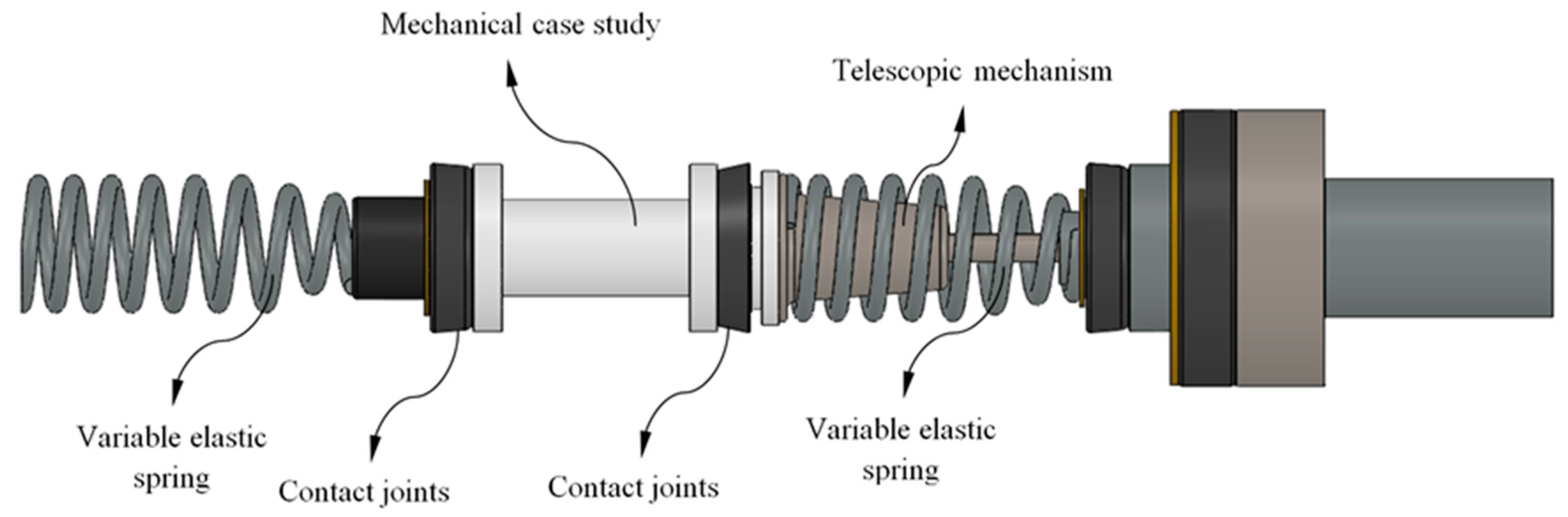
Below we present the geometrical requirements of the FDM mechanical part under study. In addition, aspects that affect the selection of the 3D FDM material in the boundary mechanical specifications and in the load scenario for the studied part are described. The mechanical part which is the object of study belongs to an automotive system shown in
Figure 1.
The end part under study presents a cylindrical geometry of revolution with a variable cross-section along its longitudinal axis (see
Figure 1). This part acts as a centering axis for an elastic spring and a telescopic mechanism with an elastic and damping component. Both elements, spring and mechanism, are located on the two ends of the part. The links between elements that make up the automotive assembly (see
Figure 1) are represented by contacts activated by the loads supported by the printed part. The study part has been produced with an FDM additive process and by using a reinforced plastic material composed of a PA6 matrix, which is Nylon, and fiberglass. The reinforced GF-PA6 has been adapted and optimized by the supplier of the material [
46] for use in the FDM process. The commercial name for the reinforced GF–PA6 [
47] is Nylstrong. GF–PA6 is characterized by having a great impact strength and an appropriate balance between hardness and mechanical strength. Additionally, its high thermal strength makes GF–PA6 suitable for industrial and mechanical purposes [
47]. The GF–PA6 filament comprises polyamide 6 with fiberglass, polyamide 6 with glass spheres and calcium carbonate as nucleant, with the ratio between spheres and fibers being 20%–30% [
47]. A disadvantage in using Nylon PA6 for manufacturing industrial applications is the fact that this material absorbs moisture, reducing the strength and stiffness of the part obtained. To solve this problem, the GF–PA6 filament prior to the manufacturing process should undergo an isothermal heating treatment based on drying the filament in an oven at 60 °C for a period of approximately 6 h.
Table 1 shows the physical, mechanical and main Nylstrong GF–PA6 characteristics for FDM uses [
47].
The part under study is subjected to a uniaxial compression stress state, determined by the contact of the elastic components that make up the mechanical assembly (see
Figure 1). The load scenario is defined by a unidirectional axial force applied at one end of the part, the boundary condition being a fixed support at the opposite end. The compression tensile yield stress for the printed end part has been obtained analytically from the classical structural analysis, introducing the values of the uniaxial compression load to which the part is subjected and the tensile yield stress of Nylstrong GF–PA6 (see Equation (1)).
The tensile yield stress of the studied end part is given by σ
y [MPa],
Across [mm
2] is the area of the part cross-section,
Fc [N] is the uniaxial compression load and
L represents the part length along the Z axis (see
Figure 2 and
Figure 3, and Equation (2)).
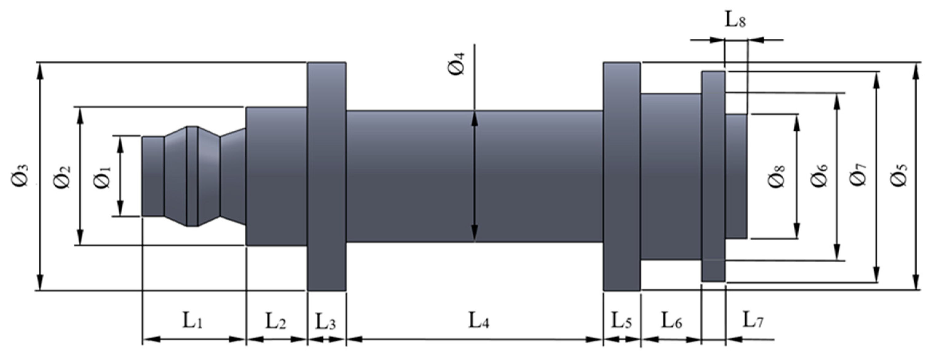
The global dimensions of the mechanical part have been determined by the requirements and specifications of the final product design. The variables
F1,
F2,
F3,
F4,
F5,
F6,
F7, and
F8 indicate the dimensions of the different diameters and
L1,
L2,
L3,
L4,
L5,
L6,
L7, and
L8 indicate the set of partial lengths along the axis. The values of the set of variables are presented in
Table 2.
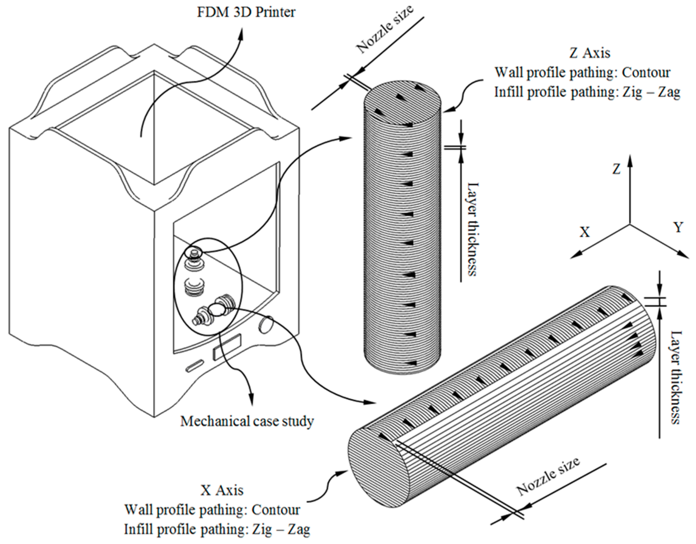
The manufacture of the part has been carried out via FDM technology using the 3D printer Ultimaker 2+ [
48]. The printing dimensions of the FDM printer are 223 mm on the X-axis, 223 mm on the Y-axis and 205 mm on the Z axis. The mechanical properties of additive manufactured parts are affected by both the unprinted material properties and the manufacturing method. FDM manufactured parts for industrial applications must be structurally resistant in a similar way to the original part produced with conventional processes (for example, injection molding). It is recommended when possible to align the load/stresses with the strongest orientation of the fiber by means of the manufacturing direction of the component. In order to analyze the manufacturing direction that maximizes the structural behavior and compressive strength of the manufactured parts made of GF–PA6, six (Z-axis, see
Figure 3) and five (X-axis, see
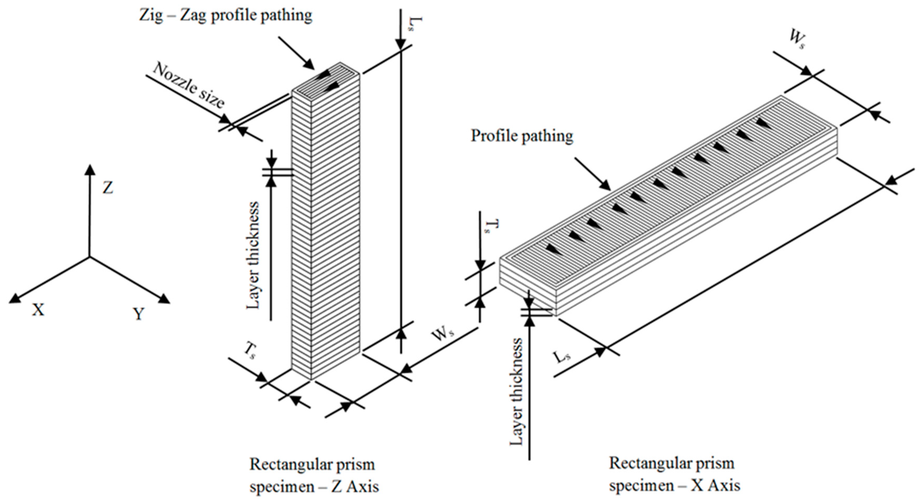
Figure 3) test specimens have been manufactured. The geometries presented have identical dimensions, with five of them manufactured in a horizontal position along the transverse manufacturing direction (X-axis) and the rest in a vertical position along the Z axis (see
Figure 3). The specimens have been manufactured from top to bottom following the positive axis direction of the FDM printer. Thus it is possible to analyze the influence on the mechanical behavior of the different manufacturing orientations in a scenario of stress in uniaxial compression. This information is relevant for the real industrial manufacture of the part.
As shown in
Figure 3, the geometrical paths used to manufacture the layers of the printed parts have been contour profiles for the external wall and zig-zag paths for the inlet pattern.
Table 3 indicates the values of the main parameters used for configuring the production process. The product requirements for the printed part have been adjusted to the specifications demanded for the FDM manufacturing process. The printed parts required supports for their manufacture both in horizontal positioning along the X-axis and vertical positioning along the Z-axis.
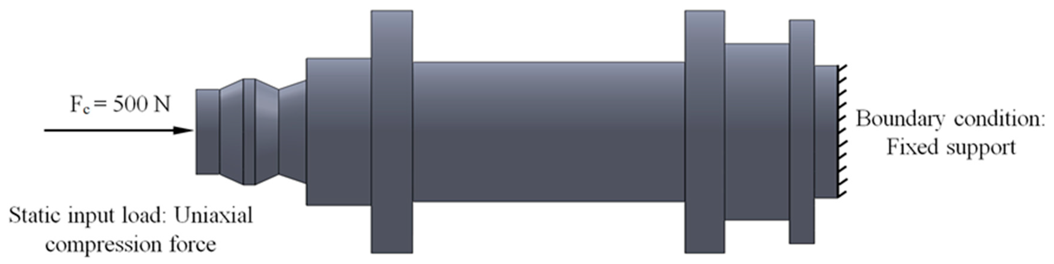
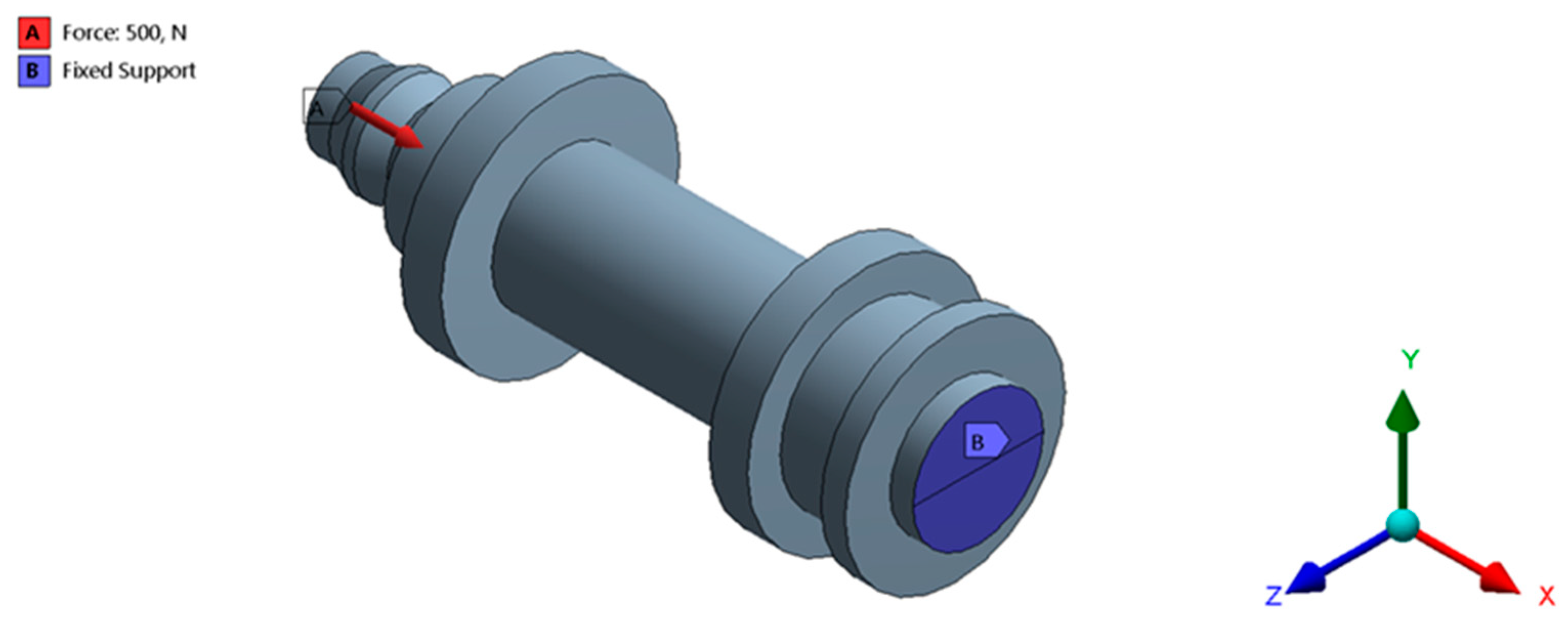
The set of loads and the boundary specifications for the printed part are presented in
Figure 4. As shown, the maximum compressive force that the part has to bear in working position is equal to 500 N. This force is applied to the opposite end of the part to which the boundary requirements have been proposed (see
Figure 4). The boundary specification established for the studied part is a fixed support on the opposite side to where the force is applied (see
Figure 4).
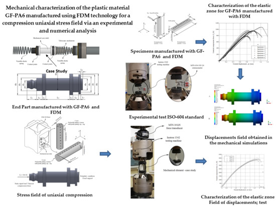
2.2. Experimental Tests
In the present manuscript, two experimental analyses have been carried out in order to evaluate the structural behavior of the printed part and mechanically characterize the behavior of the reinforced material Nylstrong GF–PA6. Firstly, the mechanical and elastic features of Nylstrong GF–PA6 have been characterized by using 3D printing specimens with prismatic geometry following the requirements of the ISO-604 standard (2003) [
49]. Secondly, the printed part under study was subjected to an experimental test to evaluate its structural behavior under a uniaxial compression stress state. (see
Figure 4). The results of the experimental tests allow us to establish mechanical parameters such as compression yield stress, displacements and loads along its elastic area until reaching the compression yield stress, compressive stiffness, and ultimate yield stress. Successively, after the mechanical and elastic characterization of the Nylstrong GF–PA6 a set of static structural numerical simulations has been defined for the 3D printed part. In this line, it is possible to contrast the results obtained from the numerical simulations with the results obtained in the experimental tests, validating the methodology for defining and configuring the numerical simulations and characterizing the elastic and mechanical behavior of the reinforced plastic material under study.
The characterization of the elastic and mechanical properties of the Nylstrong GF–PA6 3D printing material has been determined from the ISO-604 standard. This standard determines the methodology required to define the elastic and mechanical properties of a plastic subjected to a tensile state uniaxial compression. The experimental tests are carried out by using 3D printing specimens with parameterized prismatic geometry (see
Figure 5) and manufactured according to the main directions X and Z in which the material properties have been determined.
Table 4 shows the magnitude of the geometric variables used for the calculation of both the uniaxial compression elastic module and the compression yield stress. The magnitude of the manufacturing specifications for producing the specimens along the X and Z directions is shown in
Table 3, and these are the same as those employed for manufacturing the end part.
According to the ISO-604 standard used in this manuscript, at least five 3D printing specimens must be tested experimentally for each printing direction in which the mechanical and elastic properties of the plastic material must be obtained. The main directions of analysis of the printed part are X and Z (see
Figure 3 and
Figure 5), and for this purpose, a total of 11 specimens (five on the X-Axis and six on the Z-Axis) have been manufactured for the experimental tests, all of them having the same dimensions and manufacturing configuration as the end part.
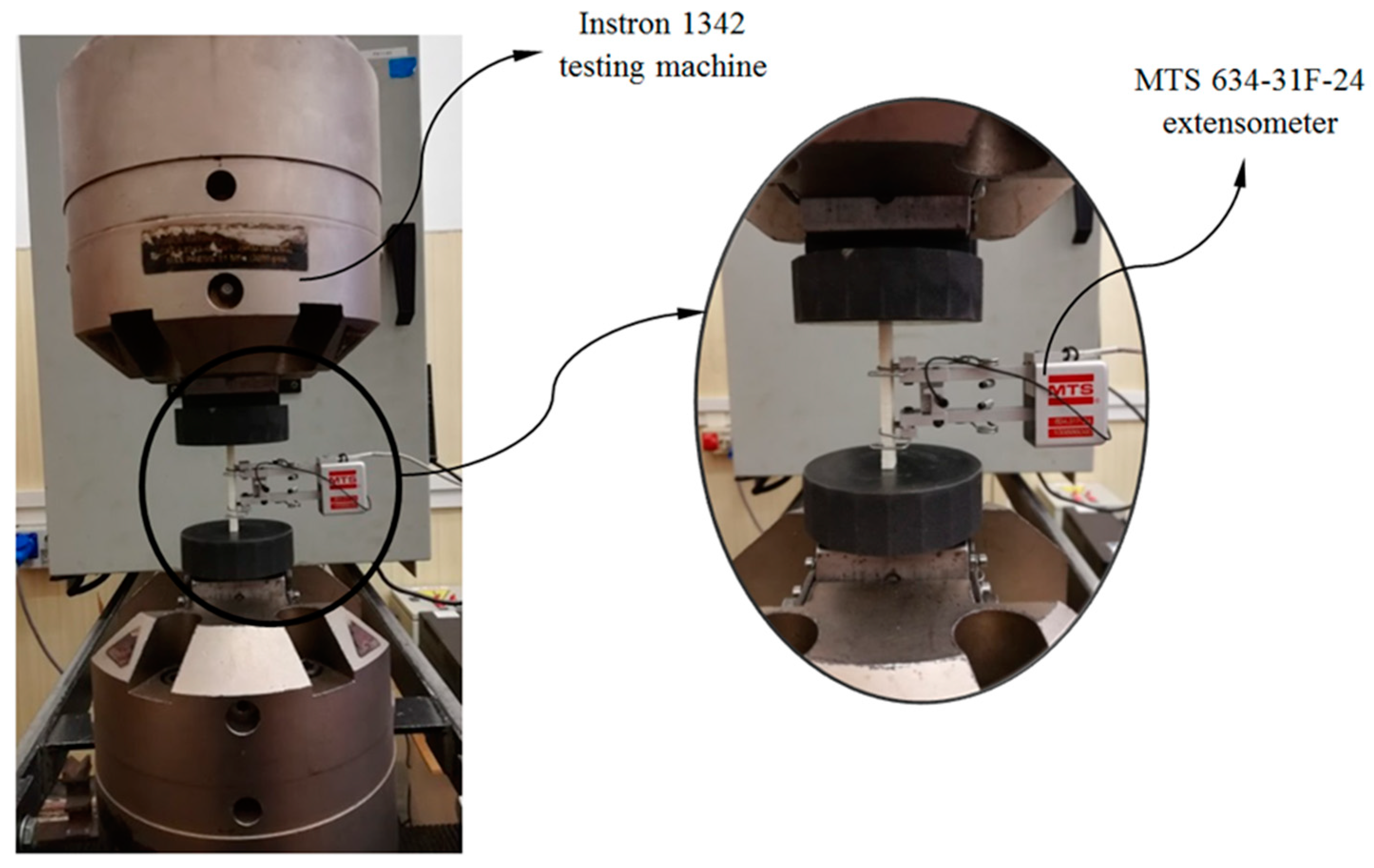
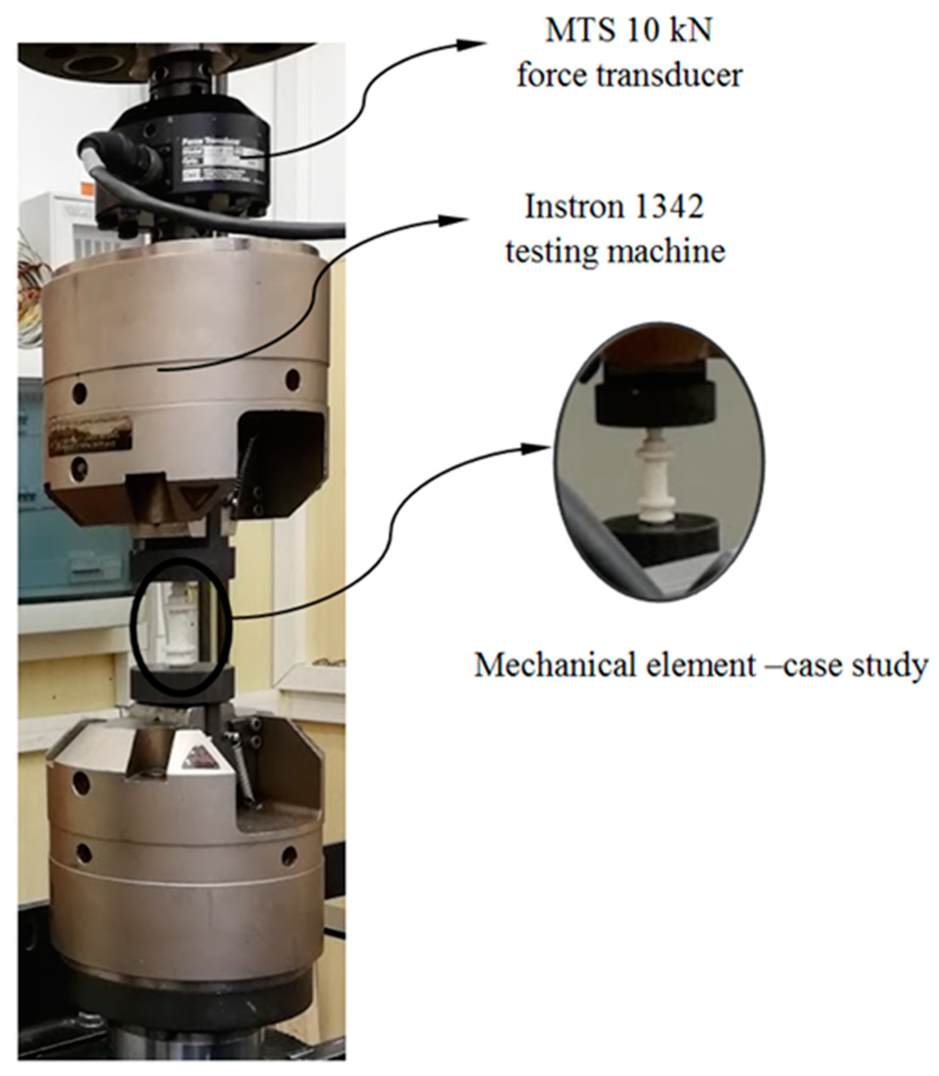
Figure 6 shows one of the test specimens located in the compression test machine prior to the experimental test. As is shown, the ends of the specimen are located between the compression machine supports, maintaining the parallelism between both machine supports and the flat supporting surfaces of the specimens. Before starting the experimental test the compression machine makes an adjustment, at low compression speed, of the contact between the supports and the flat contact surfaces of the specimens. In this way is possible to avoid eccentricity and flexo-compression stresses on the specimens during compression tests. Through the experimental test of the specimens the compression speed defined in the machine, from the beginning of the test until the moment of the breaking of the specimens, is constant and equal to 1 mm/min, in line with standard ISO-604 (see Equation (3))
where
v [mm/s] represents the compression speed of the test and
Ls [mm] the length of the specimens tested. In order to obtain the magnitudes of the stress and strain field in the central region of the 3D printing specimens without inertia delay, axial extensometers have been used (see
Figure 6). The axial extensometer model used during the experimental uniaxial compression tests on 3D printing specimens is MTS 634-31F-24. On the other hand, the compression machine used to carry out the experimental tests of the 3D printing specimens and the mechanical element under study is the Isntron 1342 (see
Figure 6), which complies with the ISO-5893 standards. The test machine Instron 1342 is servohydraulic and includes two supports made of hardened steel and parallels with a plane perpendicular to the compression load axis. In addition, it also incorporates a force transducer mechanism MTS 10 kN, used to record the uniaxial compression load applied to each specimen during the experimental tests.
Table 5 and
Table 6 show the technical characteristics of the testing machine and the extensometer used for the experimental tests.
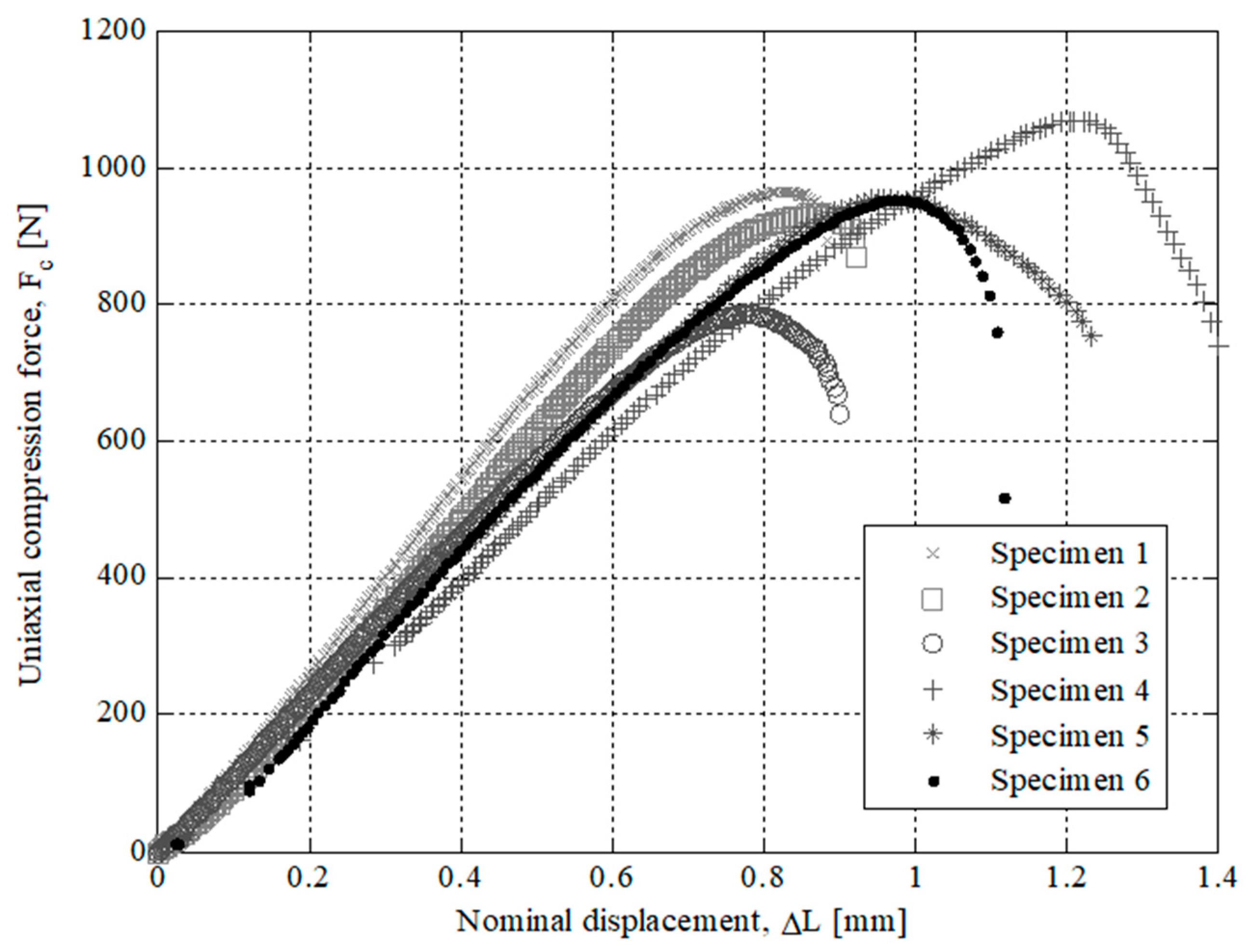
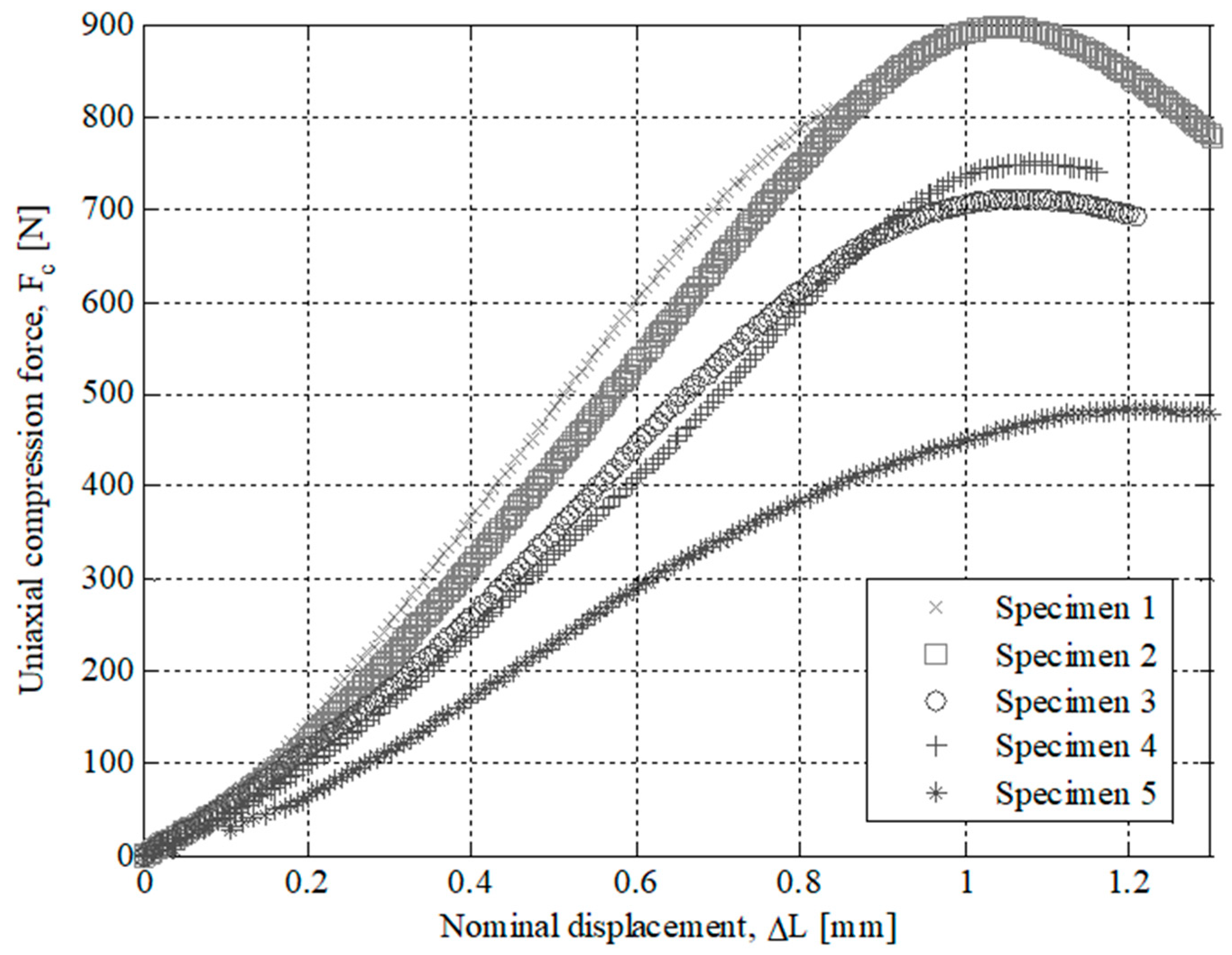
The results of the experimental tests for the specimens tested are presented in
Figure 7,
Figure 8,
Figure 9 and
Figure 10. On the one hand,
Figure 7 and
Figure 8 show the field of uniaxial compression forces and the field of nominal displacements for the 3D printing tested specimens from the beginning of the experimental test until the structural failure of the specimens. The magnitude of these experimental variables is obtained through the transducer mechanism MTS 10 kN included in the testing machine. On the other hand,
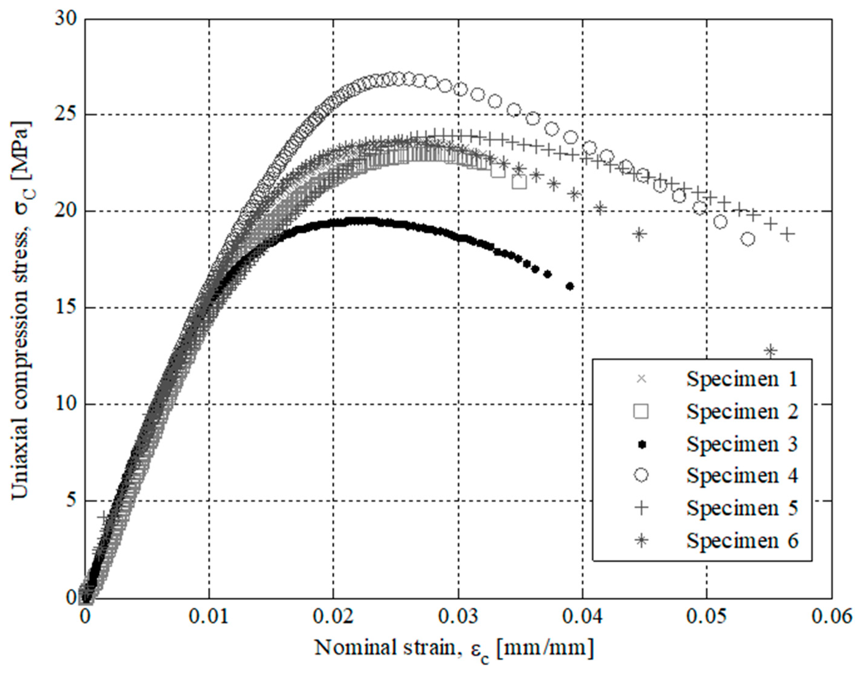
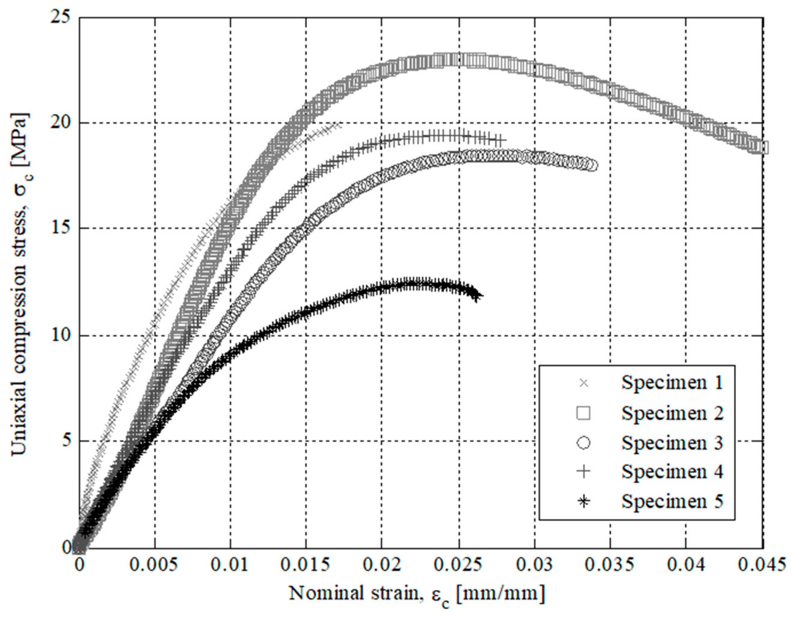
Figure 9 and
Figure 10 show the field of stresses and deformations from the beginning of the experimental test until the structural failure of each specimen. This measurement is taken in the central-cross section of the 3D printing specimens (see
Figure 6), which in turn is the most representative area to achieve the elastic and mechanical material features related to the ISO-604 standard. Similarly,
Figure 7,
Figure 8,
Figure 9 and
Figure 10 show the results obtained for the specimens printed in the direction of the X and Z axis
As shown in the stress-strain curves (σ
c-ε
c), see
Figure 9 and
Figure 10, the behavior of Nylstrong GF–PA6, used in the manufacture of the X-Axis and Z-Axis tested specimens, is elastic in the initial part of the curves until it reaches the yield strength at a compression value σ
y (see
Table 7 and
Table 8). From this magnitude of stress, the process of non-linear plasticization of the specimens begins until they reach the fracture stress σ
f. It can be seen that there is a difference in the elastic behavior in the initial part of the stress-strain curve (σ
c-ε
c) between the Z-Axis tested specimens and X-Axis tested specimens. On the one hand, Z-Axis tested specimens have a purely linear elastic behavior (see
Figure 9), obtaining the elastic module from two pairs of uniaxial compression stress values corresponding to the nominal strain values of 0.0025 and 0.0005 (see Equation (4)), following the requirements of the ISO-604 standard.
However, X-Axis tested specimens present a non-linear elastic behavior (see
Figure 10) since the evolution of uniaxial compression stresses versus nominal strains is not defined by a line with a constant slope. This non-linear elastic behavior, typical of plastic and foam materials, can be characterized by two elastic parameters: tangent elastic module and secant elastic module. In this way, the tangent elastic modulus is used to characterize stress states of the plastic material in the initial area of the stress-strain curve (σ
c-ε
c) while the secant elastic modulus is used to characterize tensile states of the plastic material close to the compressive yield stress σ
y. Therefore, given that in this manuscript the end part is subjected to a scenario of loads and boundary requirements that cause a stress state of uniaxial compression close to the yield stress σ
y, the secant module is used as an elastic parameter to characterize the elastic behavior of plastic material for 3D printing with Nylstrong GF–PA6. The magnitude of the secant elastic modulus is established as a γ percentage of the uniaxial compression elastic modulus (see Equation (5)). The value of this percentage γ can vary between 0.70 and 0.85, depending on the type of plastic or foam material and the non-linear elastic region of the stress-strain curve (σ
c-ε
c) where the mechanical behavior of the material is analyzed.
To determine the elastic compression module of the 3D printing material Nylstrong GF–PA6, both for the specimens manufactured in X-axis and in Z-axis (see
Table 7 and
Table 8), the arithmetic mean of Young’s modulus compression values obtained for each specimen tested is established.
Table 7 and
Table 8 show the elastic and mechanical properties for the Z-axis and X-axis of Nylstrong GF–PA6 manufactured with 3D printing.
The characterization of the elastic behavior of Nylstrong GF–PA6 for FDM is carried out according to the guidelines of the analytical model of the ISO-604 standards being used for the definition of the numerical model. In this way, it is possible to validate and compare through mechanical simulations the numerical virtual results with the experimental results obtained from the tests performed on the end part.
The type of fracture that occurs in the X-axis and Z-axis tested specimens is of the fragile type. On the one hand, for the specimens manufactured in the X-axis, the fracture is related to their manufacturing process, since this is mainly caused by complete delamination between adjacent layers of plastic material. On the other hand, for the specimens manufactured in the Z-axis, the fracture is caused by the structural failure of the plastic material, which is to say when the elastic properties limit is exceeded. In both cases, the fracture is carried out in the central cross-sections of the specimens and is produced by the flexural stresses to which the specimens are subjected during their fracture process.
After performing the experimental test with the test specimens, a second experimental test has been carried out in order to analyze the structural behavior for the part under study. The printed end part has been manufactured following the main directions of analysis X and Z and maintaining in both cases the manufacturing parameters in order to evaluate the influence of the manufacturing process on the structural behavior. For both manufacturing directions, three parts have been experimentally tested. In a similar manner to the tests carried out for the 3D printing test specimens, the uniaxial compression test of the end part (see
Figure 2) has been performed on the Isntron 1342 test machine (see
Figure 11).
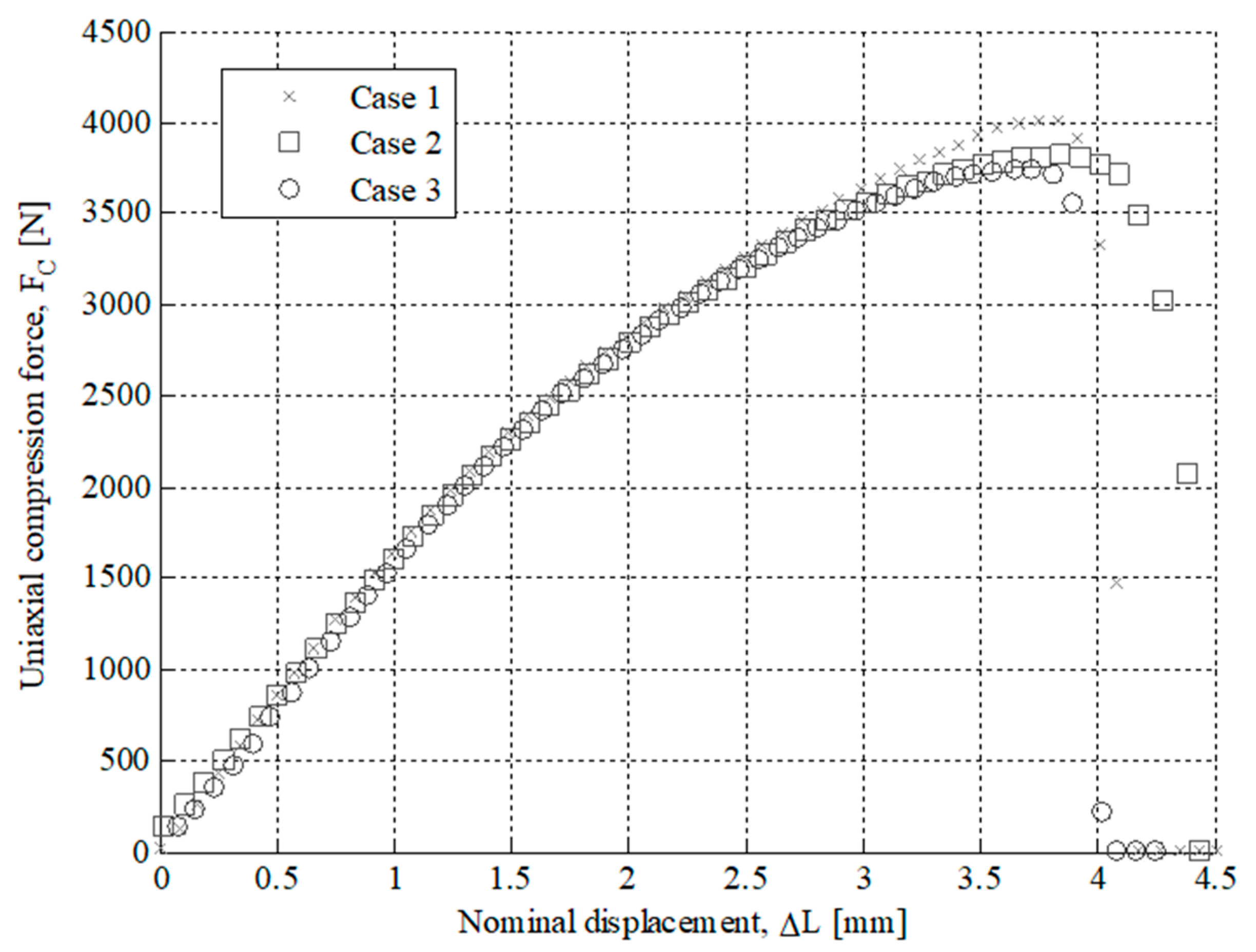
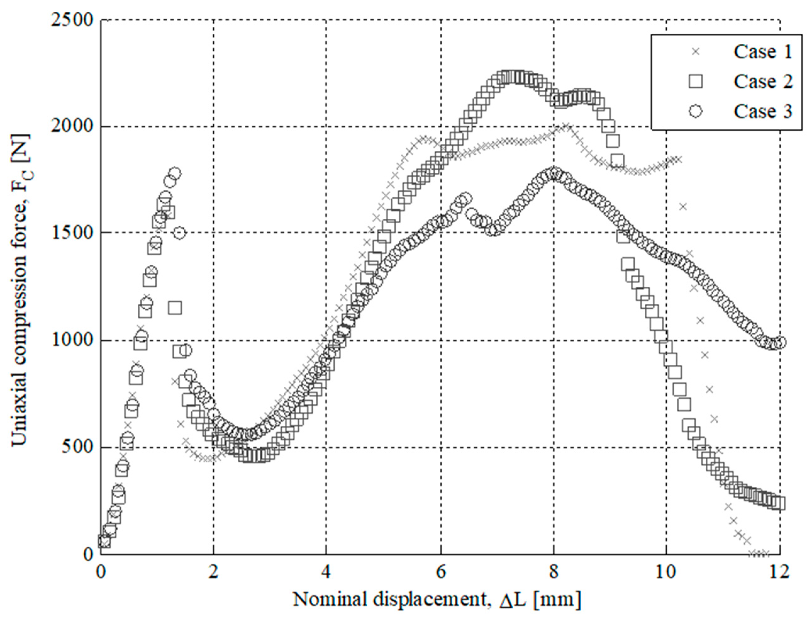
Figure 12 and
Figure 13 show the plots for the uniaxial compression load versus the field of nominal compression displacements to which the end part has been subjected in the compression test. These values were recorded until the state of fracture or structural failure for the tested end parts.
Table 9 and
Table 10 show the maximum uniaxial compression load and the nominal displacement for the point of fracture for each case study of the end part. According to the curves of uniaxial compression force versus nominal displacement (
Fc − Δ
Lc) (see
Figure 12 and
Figure 13), it can be seen that the fracture in both printing directions differs both in the value of the maximum uniaxial compression force and in the typology of the structural failure.
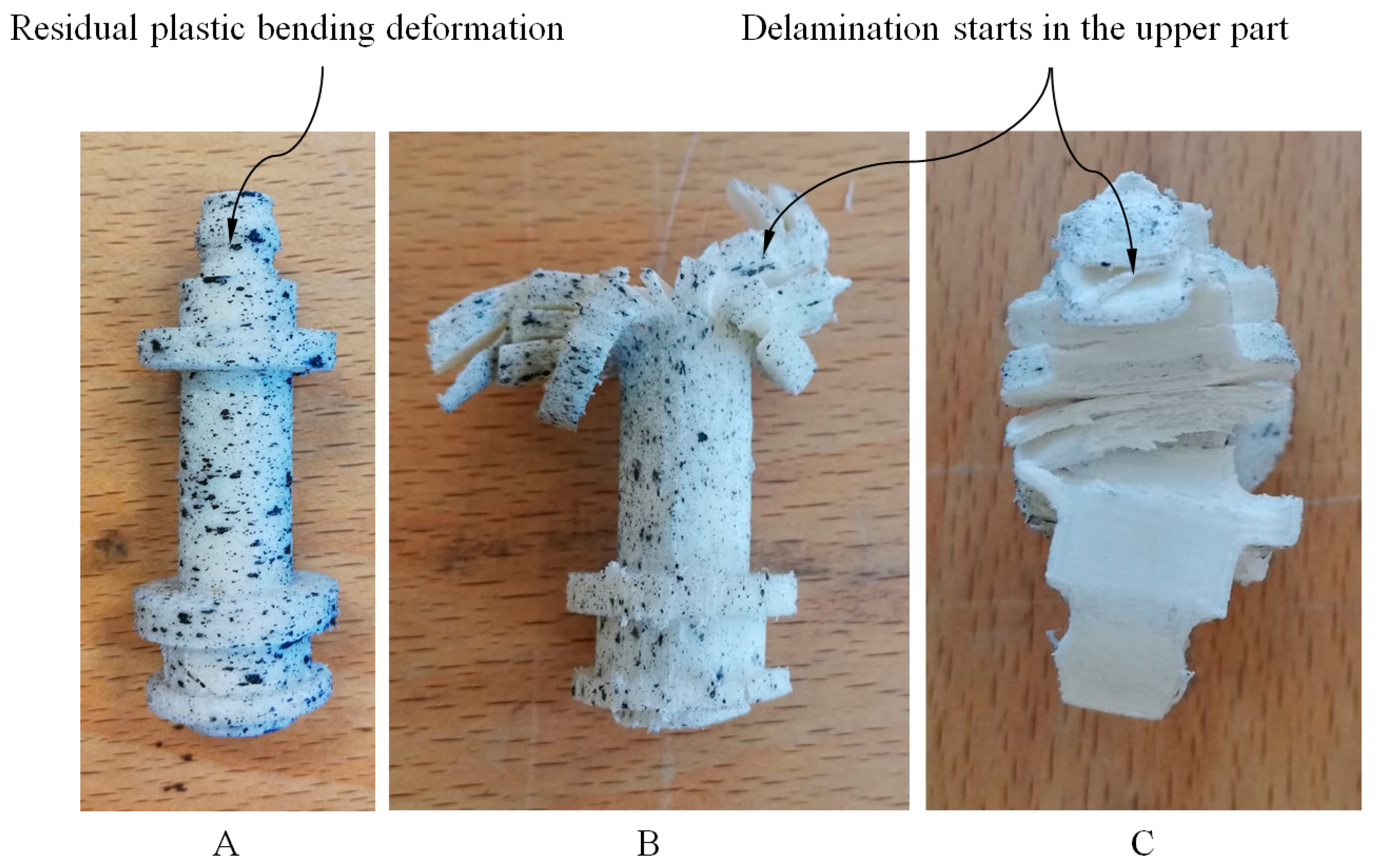
As shown in
Figure 12 and
Figure 14, for the case study of the end part manufactured in the Z-axis the fracture is caused by the residual plastic deformation produced by the bending stresses to which the central region of the mechanical element is subjected. This structural failure collapses the entire geometric domain of the end part since the initial fracture propagates along with the geometry until reaching a maximum compression force of 4018.1 N corresponding to a nominal displacement of 3.746 mm (see
Table 9 and
Figure 12). On the other hand, as shown in
Figure 13 and
Figure 14, for the case of the end part manufactured in the X-axis the fracture is generated by delamination in the upper region (see
Figure 2) extending towards the rest of its geometric domain. So once the upper region of the end part has collapsed, the magnitude of the uniaxial compression force rises again until the plasticization and structural failure of the central region of its geometric domain. This occurs for a maximum compression force of 1781.5 N corresponding to a nominal displacement of 1.309 mm (see
Table 10). In both cases, the type of fracture obtained is of the fragile type because the compressive yield stress is close to the fracture yield stress.
As shown in
Figure 12 and
Figure 13, the fracture produced during the experimental test for the end part is brittle and occurs due to the structural failure of the material in the circular cross-section where the uniaxial compression force is placed (see
Figure 4). On the one hand, for the geometry manufactured in the Z-axis, the structural failure collapses the entire geometric domain of the end part under study, since the initial fracture propagates along the geometry until reaching a maximum compression force of 4018.1 N corresponding a nominal displacement of 3.746 mm (see
Table 9 and
Figure 12). On the other hand, for the geometry manufactured following the X-axis this structural failure collapses only the geometrical region corresponding to the circular cross-sections of the end of the part where the uniaxial compression force is applied. So once this geometric region has collapsed and plasticized, for a maximum compression force of 1781.5 N corresponding to a nominal displacement of 1.309 mm (see
Table 10), plasticization of the central region of the mechanical element begins until its final breakage (see
Figure 13).
2.3. Fractography
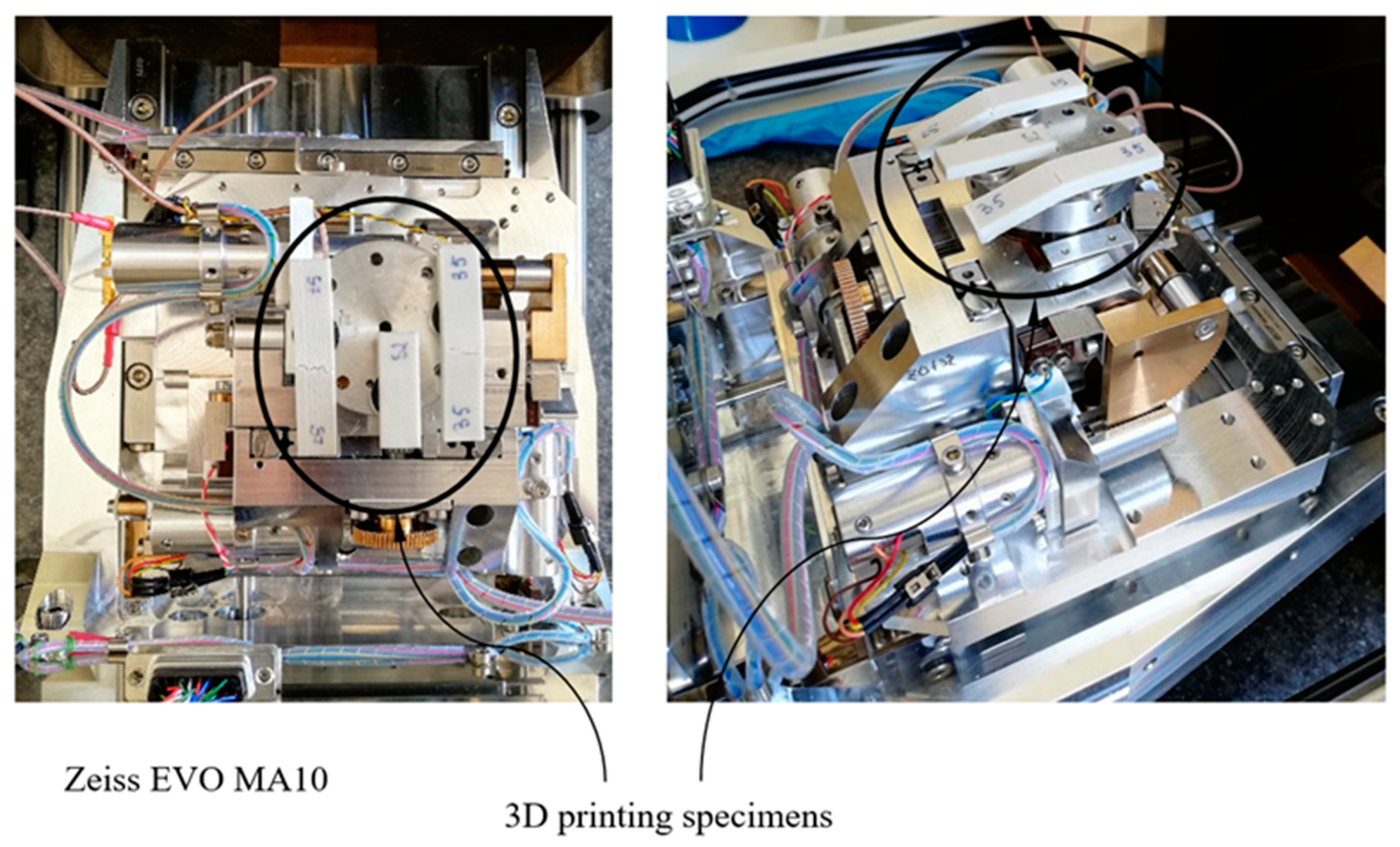
To examine the fracture surfaces of test specimens in the two different directions (X and Z), a scanning electron microscope (SEM, Zeiss EVO MA10 equipped with energy dispersive spectrometer, EDS, Bari, Italy) was used. The failure analysis of polymer specimens reinforced with short glass fibers was carried out by secondary electron imaging using beam energy of 10 kV and a probe current of 1.4 nA. The detailed setup of the SEM is shown in
Figure 15.
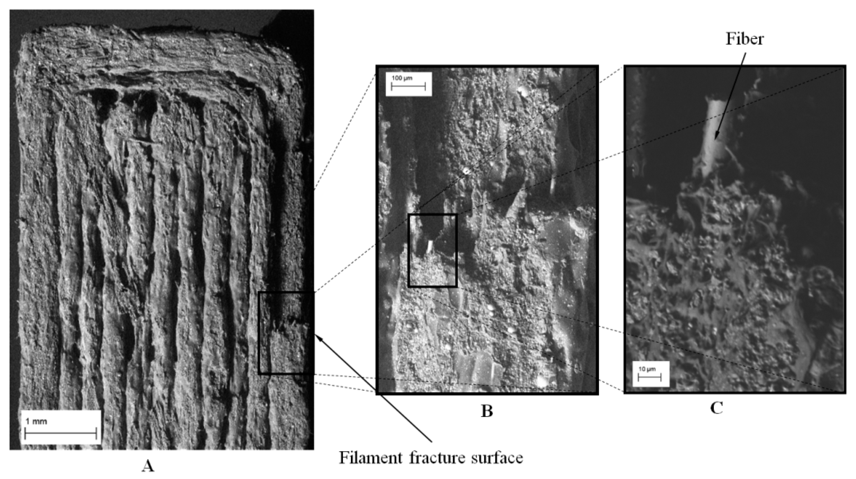
The specimen’s fracture surface analyses were conducted to examine the fracture mechanism of the fabricated specimens for the two different deposition directions. It can be noticed that the Z-direction specimen (see
Figure 16) exhibits an inter-layer brittle fracture. Generally, the fracture is due to complete delamination between two adjacent layers, while the filaments remain intact. However, the fracture growth ends with the breaking of the contour filament along the cross-section (see
Figure 16A,B). Also, in this case, the cross-section fracture surface of the filament does not show local plastic effect, but internal fibers were pulled out from the plastic matrix (
Figure 16C).
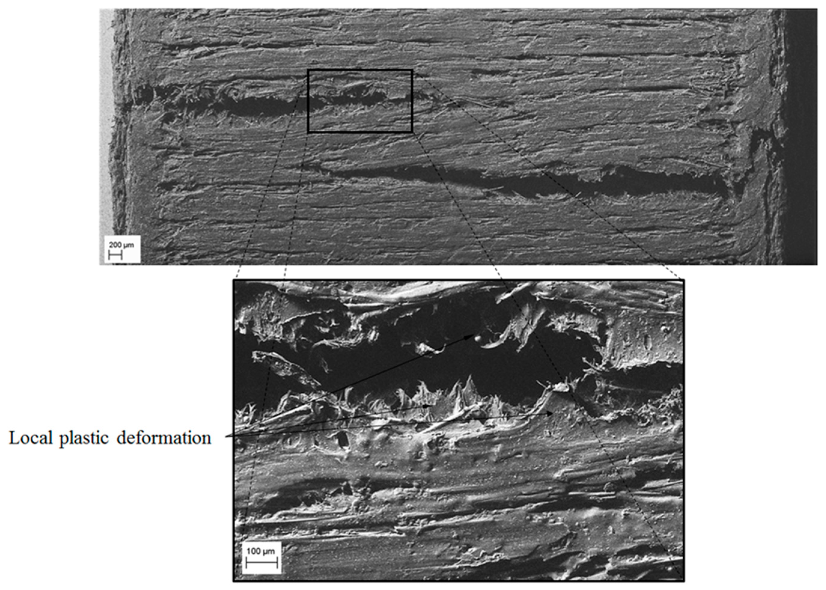
Figure 17 and
Figure 18 show the fracture surface of the X-direction specimen. The front view (see
Figure 17) shows that the fracture direction is transverse to the load direction and proceeds from the outside to the inside of the specimen. Furthermore, the edges of the fracture surface show a local plastic deformation of the matrix along the bonding between filaments. The lateral view (see
Figure 18) highlights the fact that, due to the flexion load caused by the buckling of the specimen, the crack advances from extrados to the inner part of the specimen. In this configuration, the fracture mode is mainly related to the mechanical behavior of the base material since the filaments bonding direction is perpendicular to the compressive load.
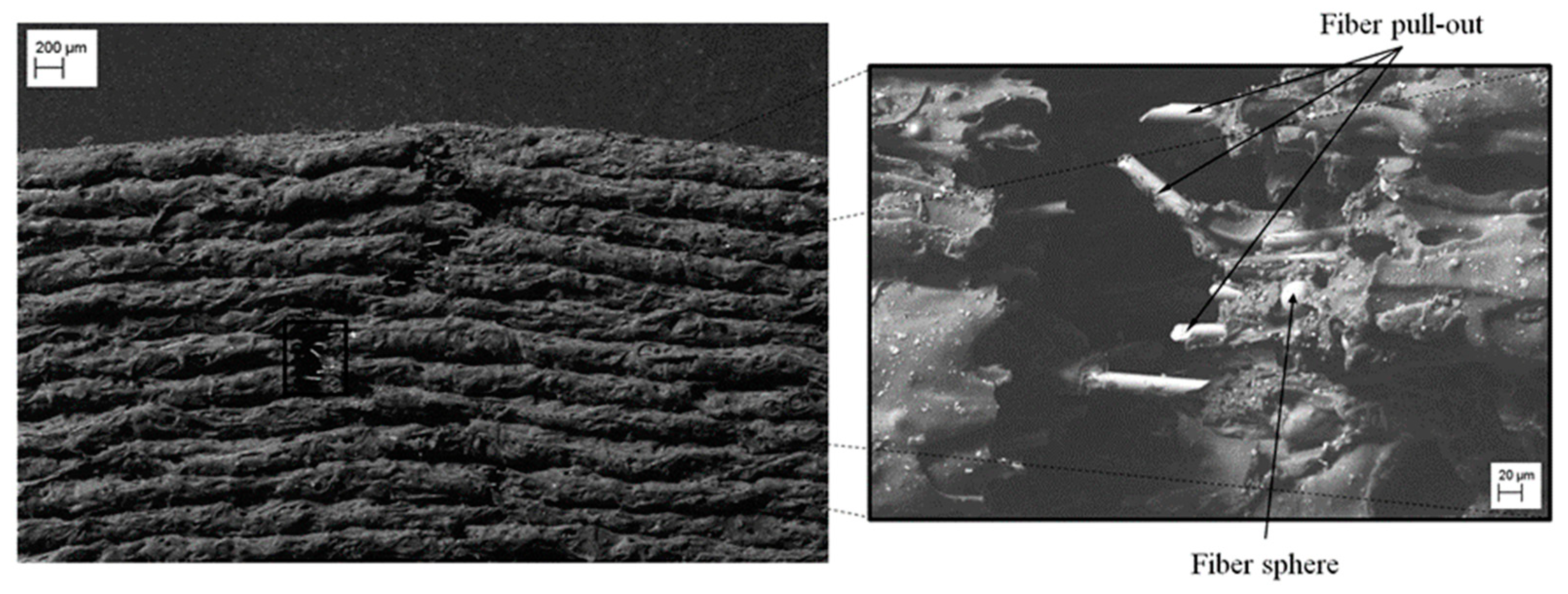
In addition, from
Figure 18 it can be noticed the pull-out and failure of the fibers along all the fracture edges. In particular, the pulled-out fibers show an even surface with an angle of 45°, typical of brittle fracture mode. Finally,
Figure 18 shows in detail the incorporation of fiberglass spheres presented by the Nylstrong GF–PA6 3D printing plastic material. According to the information provided by the supplier of the material [
47], the purpose of these fiberglass spheres is to stabilize the plastic material during its 3D additive manufacturing process and favor its contraction process in order to reduce the defectology associated with the process of manufacture.
2.4. Numerical Method
The commercial software used to perform the numerical simulations for the studied part has been Ansys Mechanical [
50].
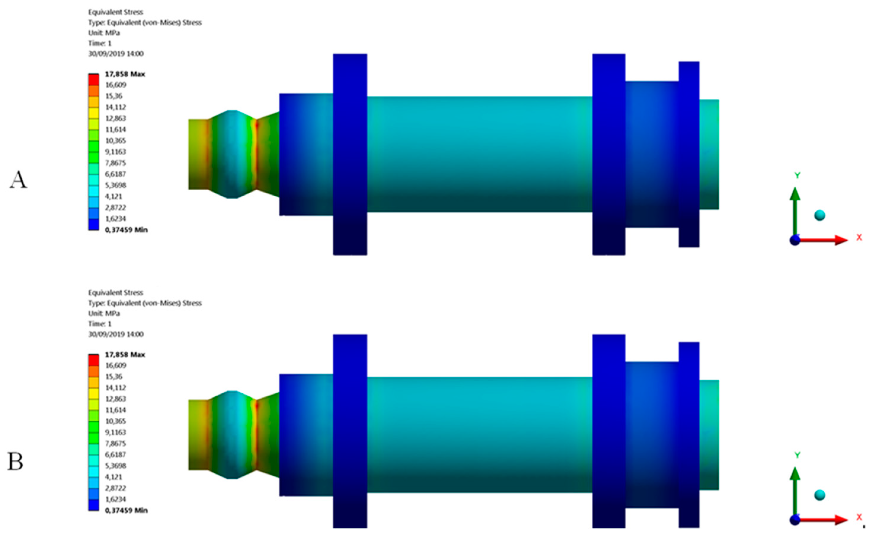
Figure 4 and
Figure 19 show the boundary conditions and the load requirements for the numerical part analysis. On the one hand, as loading scenario, a uniaxial compression force is applied along the longitudinal axis of the part at the end to the circular cross-section with diameter Ø
1 (see
Figure 2) and with a value of 500 N. On the other hand, a fixed support is located at the opposite end corresponding to the circular cross-section of diameter Ø
8 (see
Figure 2).
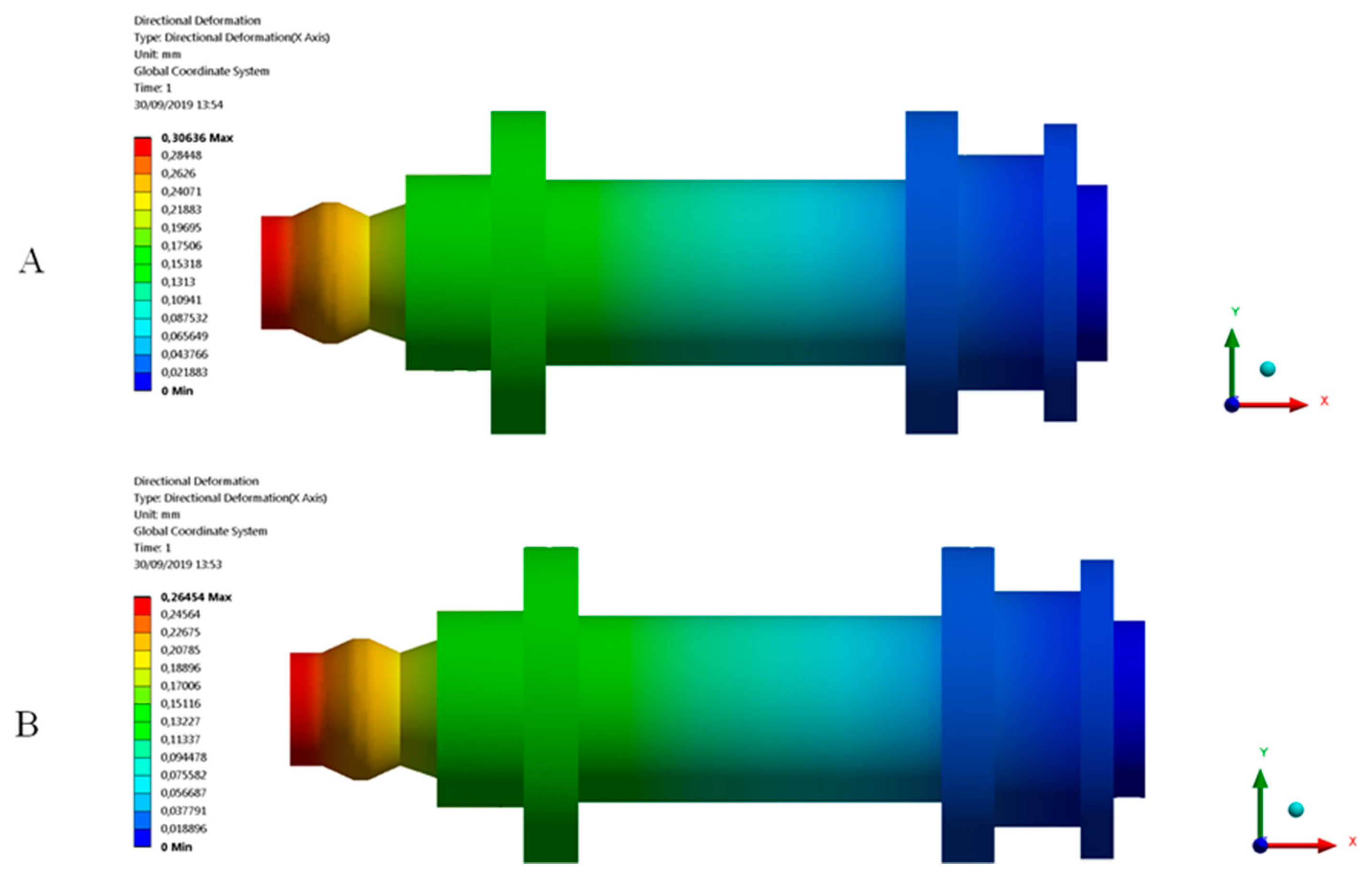
Numerical and mechanical models are established as static and elastic (see
Figure 2). Two numerical analyses have been carried out for the part geometry manufactured in the Z and X deposition directions. The objective was first to validate the methodology used for defining the mechanical and elastic properties of Nylstrong GF–PA6 in the numerical software and secondly to compare the numerical and experimental results. For the numerical analysis, the elastic material properties obtained from the experimental test carried out on the specimens both in the Z and X-axis have been employed (see
Table 7). For the first numerical analysis, Nylstrong has been defined as isotropic and elastic, with compression Young modulus constant and equal to 960.2 MPa (see
Table 7) and a Poisson coefficient of 0.38 (Value obtained from the supplier) [
47]. For the second numerical analysis, the elastic properties of Nylstrong obtained from the experimental tests of the specimens manufactured along the X-axis were used (see
Table 8). According to the experimental results, it is determined that the elastic behavior of GF–PA6, for the manufacturing direction in the X-axis, is non-linear. Therefore, the material definition for this analysis is established as elastic, isotropic and with a value of the compression secant modulus
EsX constant and equal to 1083.5 MPa (see Equation (6)). The magnitude of this elastic parameter is determined as a fraction γ of the compressive elastic modulus
EcX of the plastic material (see Equation (6)). For the manufacturing direction of the X-axis
EcX is equal to 1354.4 MPa (see
Table 8). For the numerical analysis of the printed end part in this manuscript, the γ fraction used to define the magnitude of the secant module is 0.8 (see Equation (6)), according to the criteria established in the ASTM-D695 standard [
51]. In this case, the magnitude of the Poisson coefficient is 0.38 (Value obtained from the supplier) [
47].
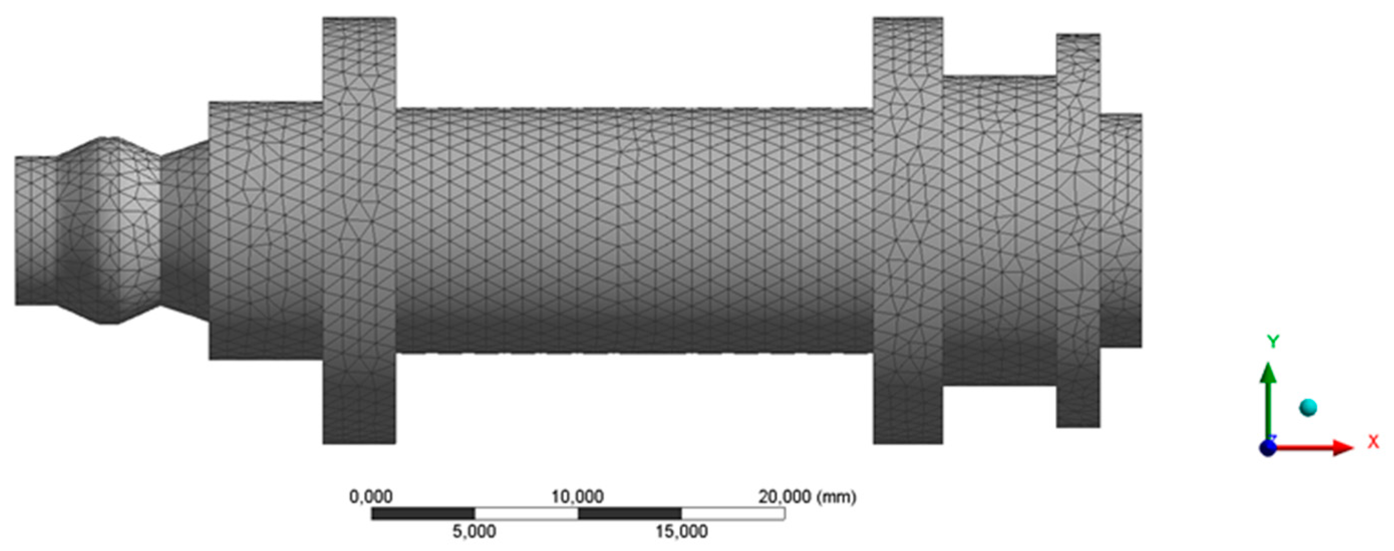
Solid structural tetrahedral elements SOLID 92 have been employed to discretize the end part topology. Each tetrahedral element is characterized by a quadratic displacement, being composed of 10 nodes where 4 nodes are located in the vertices of the tetrahedron and 6 nodes in the midpoints. Each node has three degrees of freedom including translation in the Nodal X, Y and Z directions. In order to determine the size of the mesh elements, a mesh dimensioning operation is defined, obtaining, as a result, a section size of 1 mm.
Table 11 presents the statistics for the numerical simulations performed and
Figure 20 shows the mesh. Based on the characterization model of Nylstrong GF–PA6 for the numerical simulation, the large displacement option has been used in the initial solver definition to ensure the convergence of the final solution.

 ,
, 


