
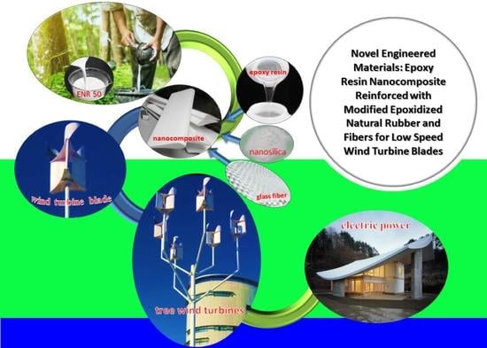
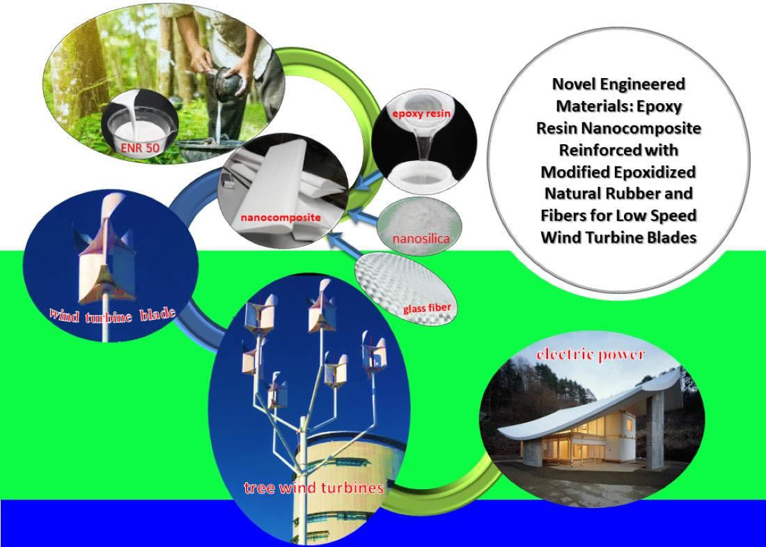
Novel Engineered Materials: Epoxy Resin Nanocomposite Reinforced with Modified Epoxidized Natural Rubber and Fibers for Low Speed Wind Turbine Blades


Abstract
:
1. Introduction
2. Experimental
2.1. Materials and Methods
2.2. Sample Preparation
2.3. Characterization
2.4. The Mechanical Properties of the Nanocomposite and Wind Turbine Blade Samples
2.5. Morphology
2.6. Thermal Properties
2.7. Forming the Wind Turbine Blades
3. Results and Discussion
3.1. Characteristics of the Samples
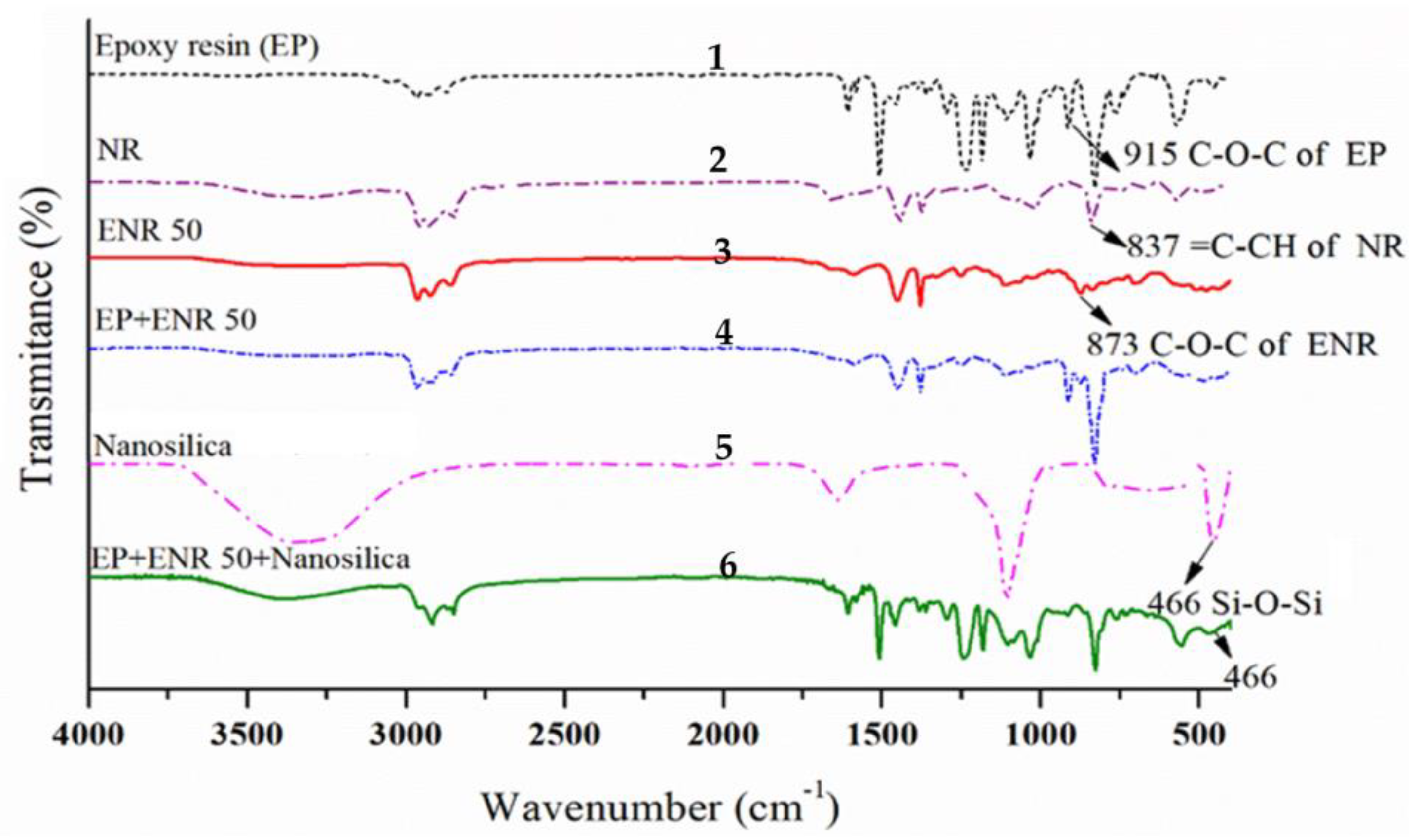
3.1.1. Fourier Transform Infrared Spectroscopy (FTIR)
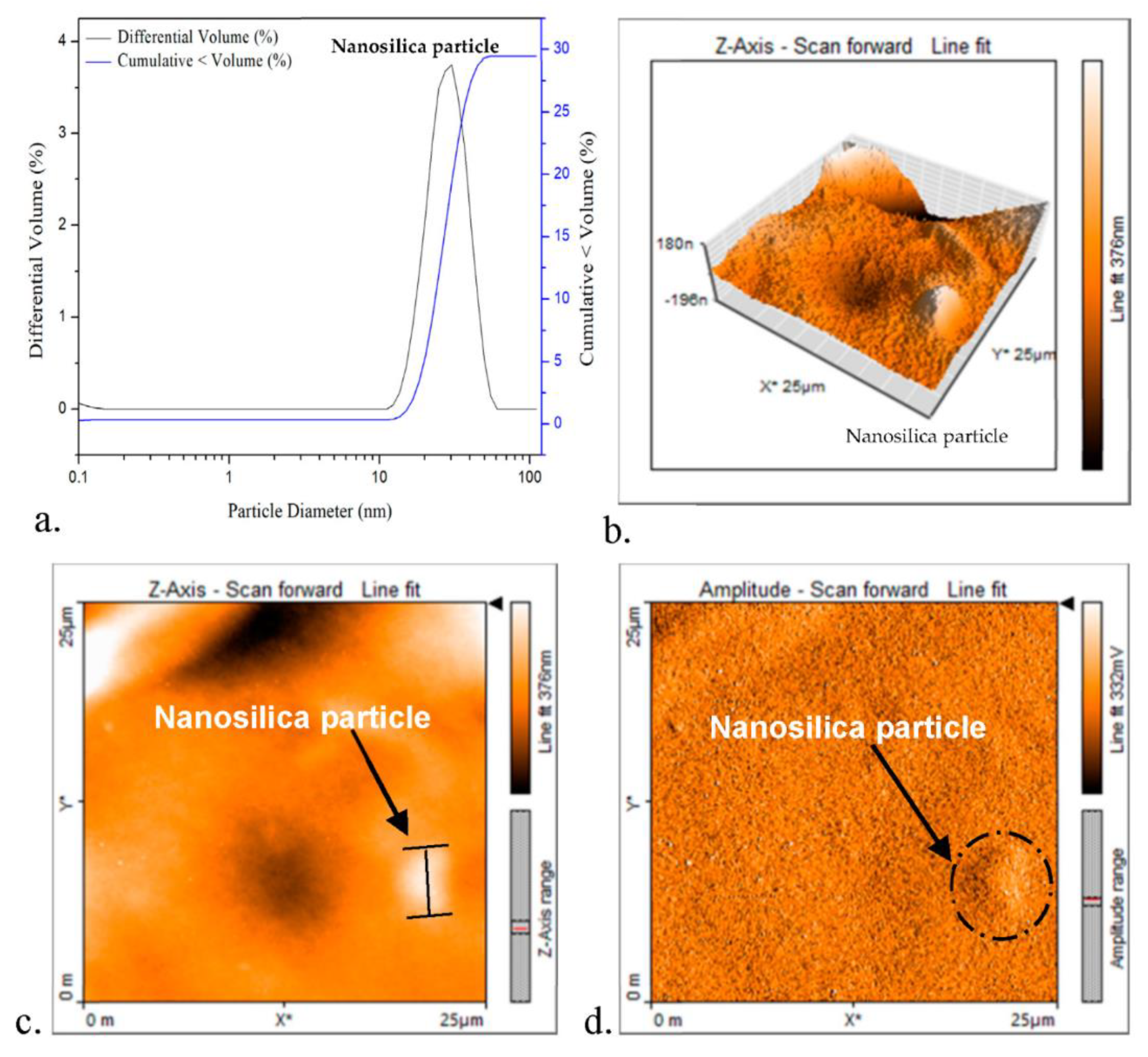
3.1.2. Particle Size of Nanofiller
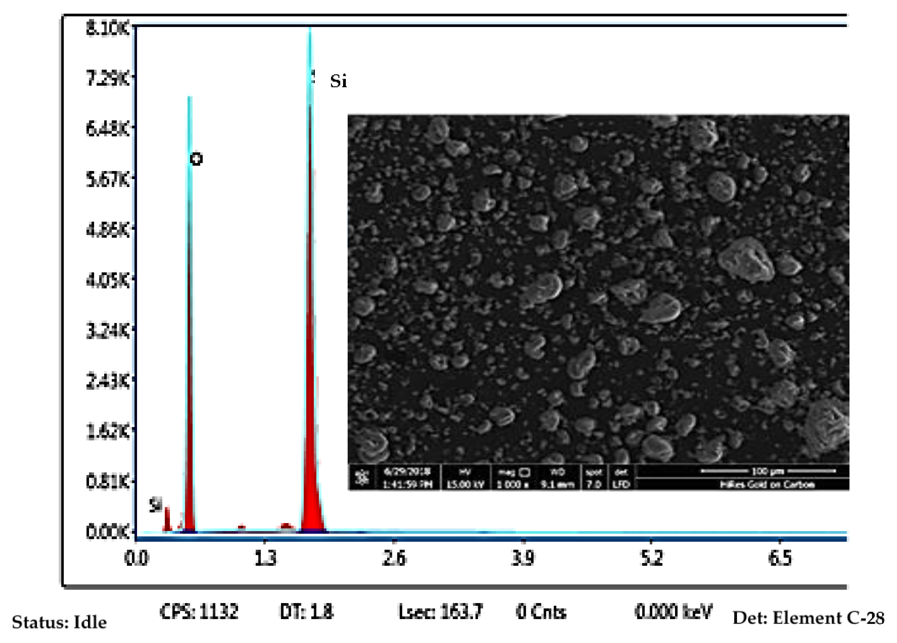
3.1.3. SEM/EDX
3.2. The Mechanical Properties of Nanocomposite Samples
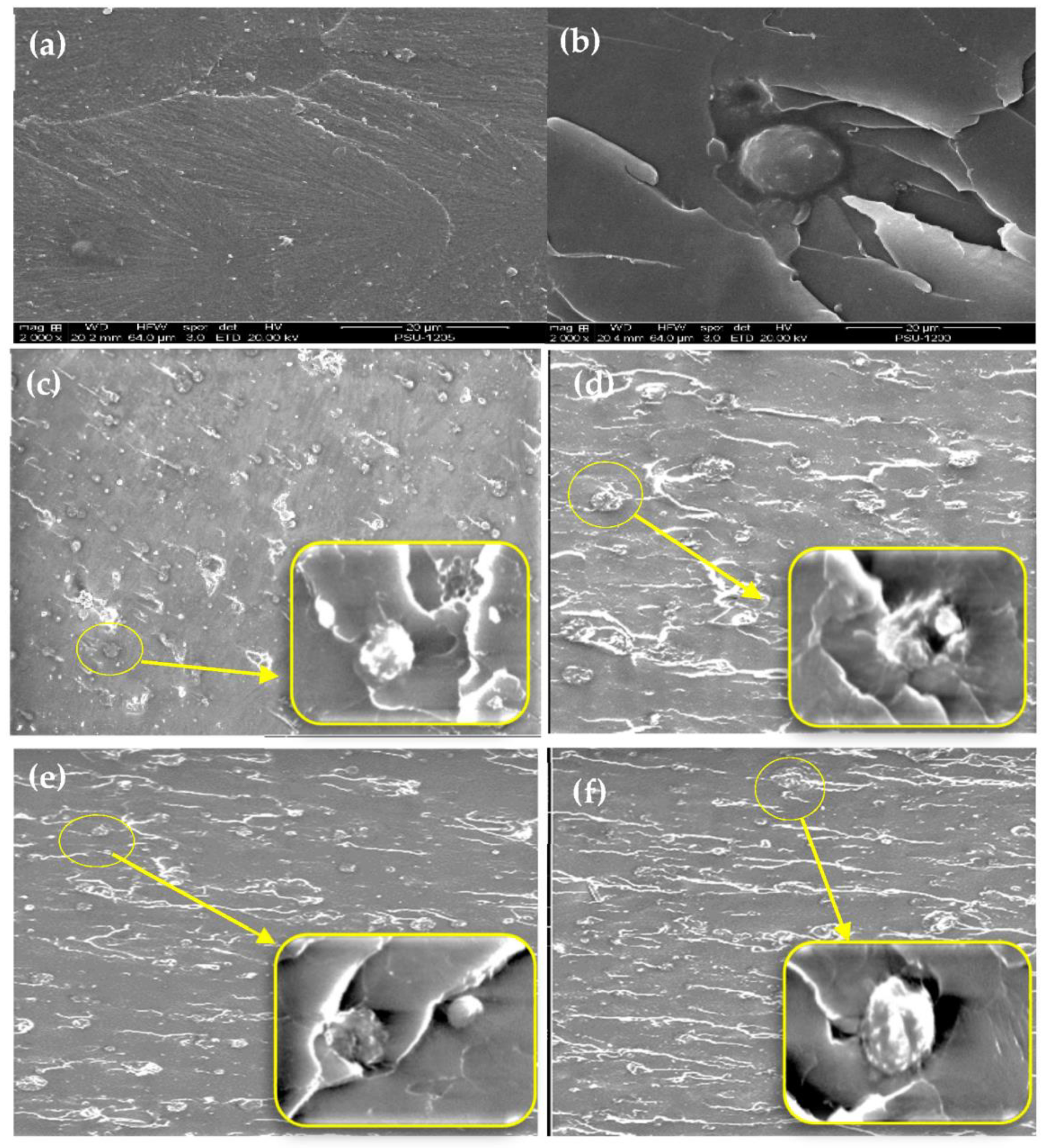
3.3. Morphology of Nanocomposites
3.4. Aging Effects on Thermal and Mechanical Properties of Nanocomposite Samples
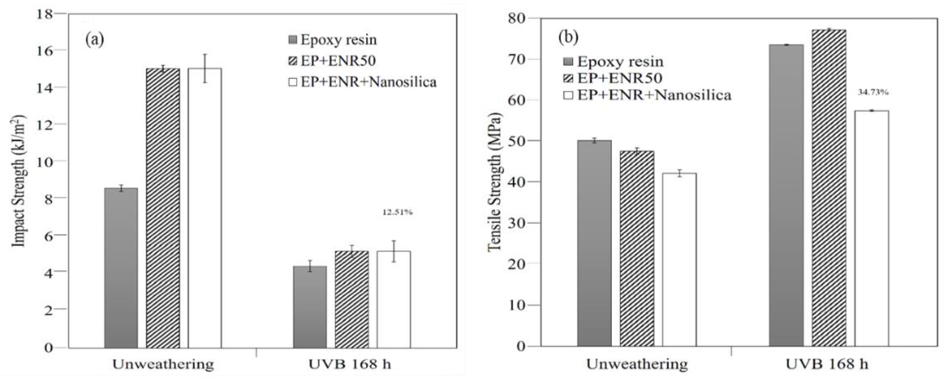
3.4.1. The Mechanical Properties of Nanocomposites
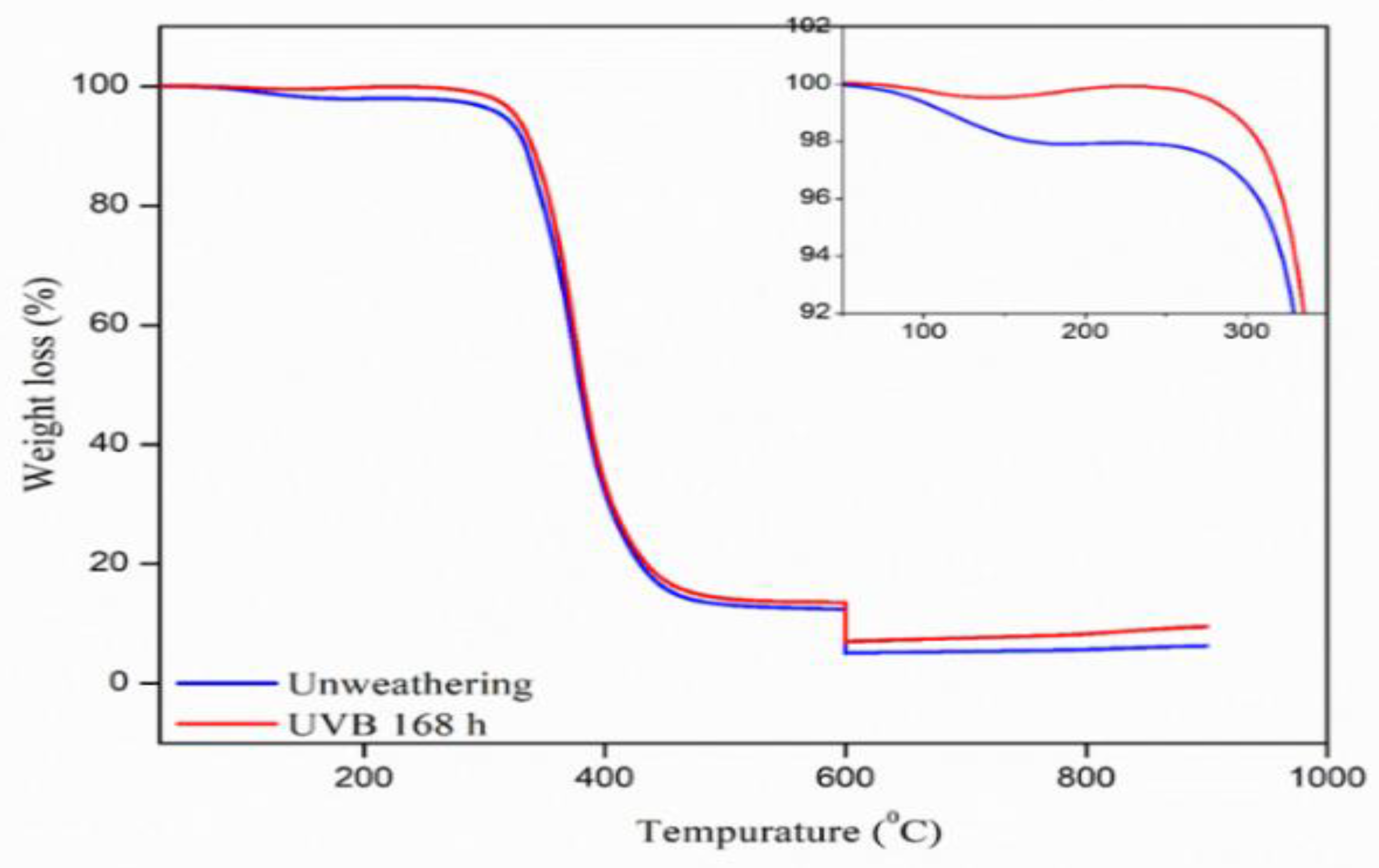
3.4.2. The Thermal Stability Investigation
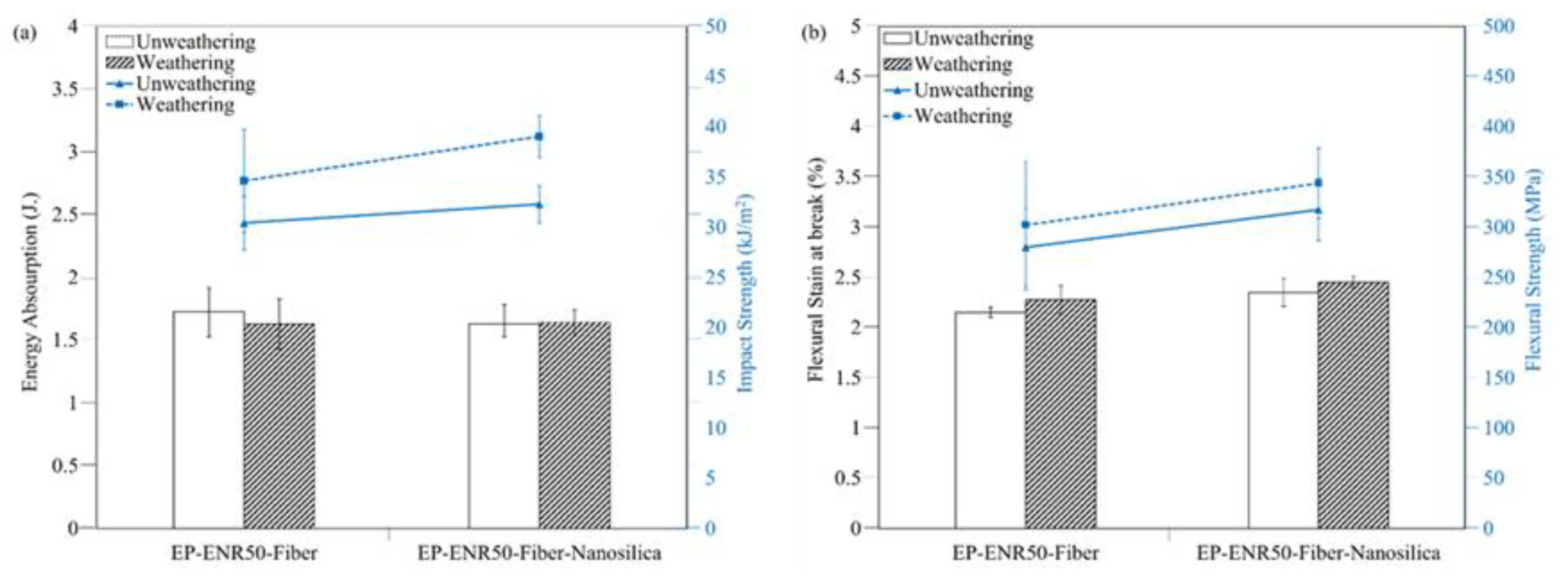
3.4.3. Mechanical Properties of Wind Turbine Blades from Nanocomposite-Fiber Samples
- −
- Impact strengths of nanocomposite-fiber samples
- −
- Flexural strength of nanocomposite-fiber samples
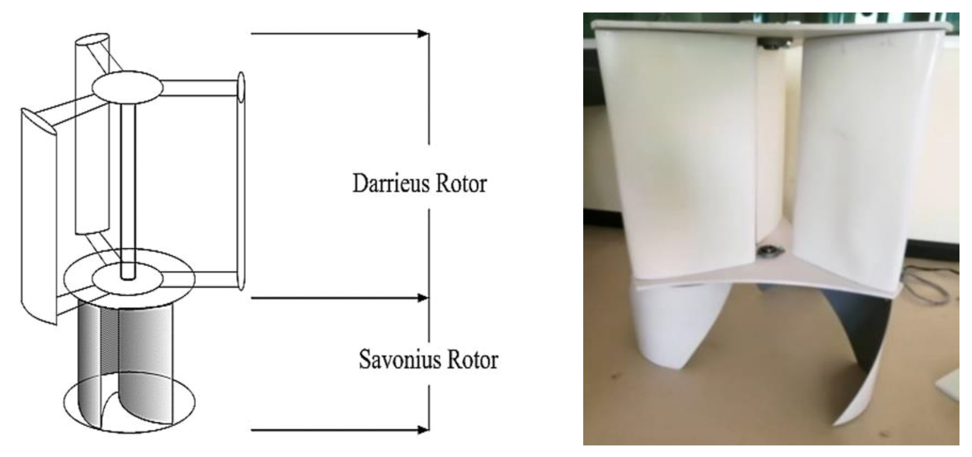
3.5. Application to Blades of a Vertical Wind Turbine
3.5.1. Forming a Wind Blade with Hand Lay-Up Technique
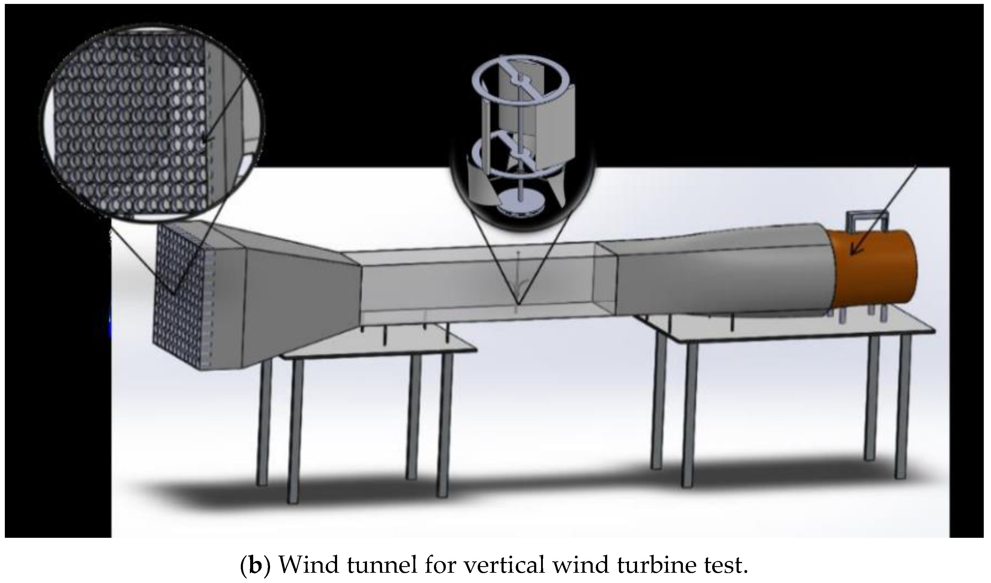
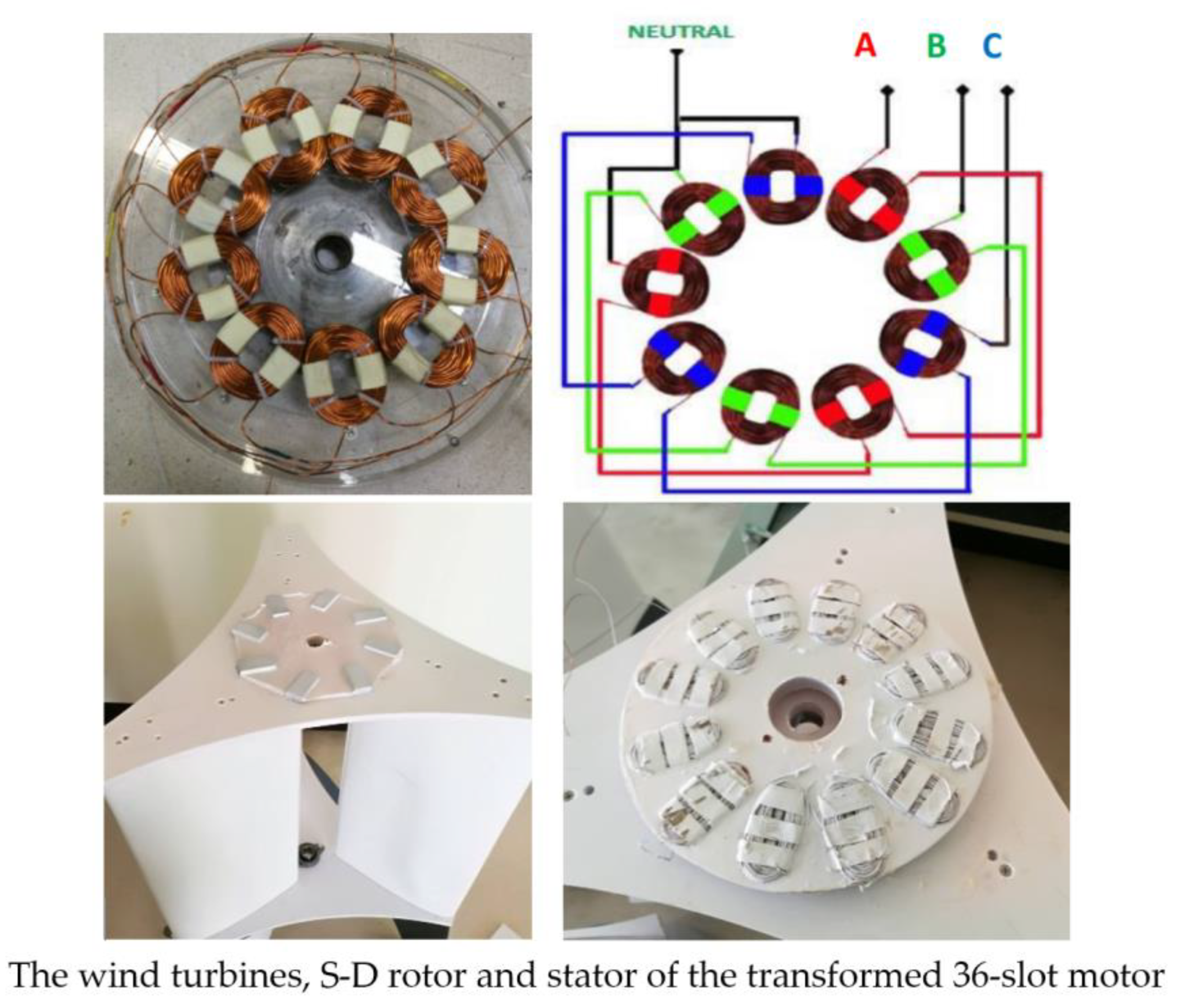
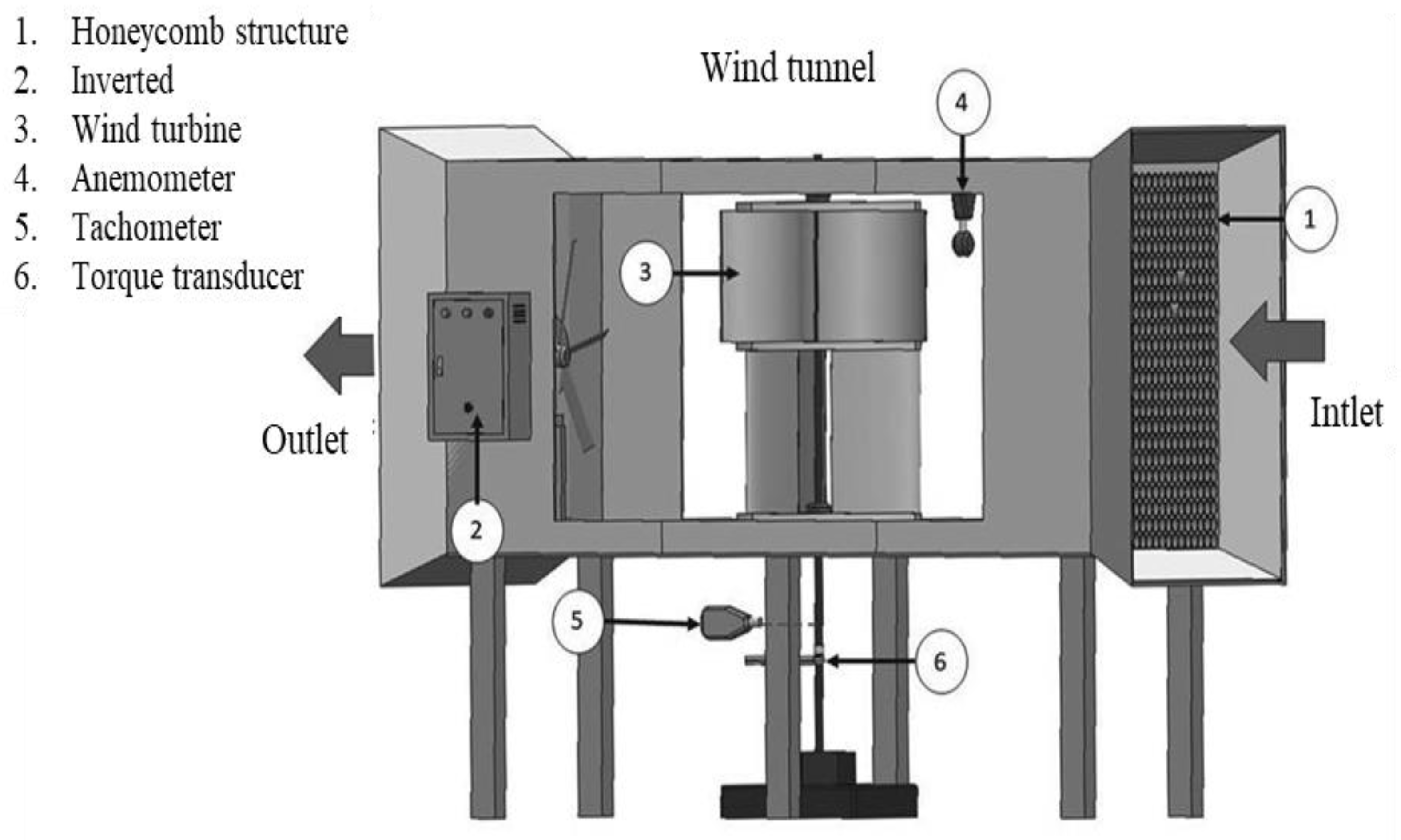
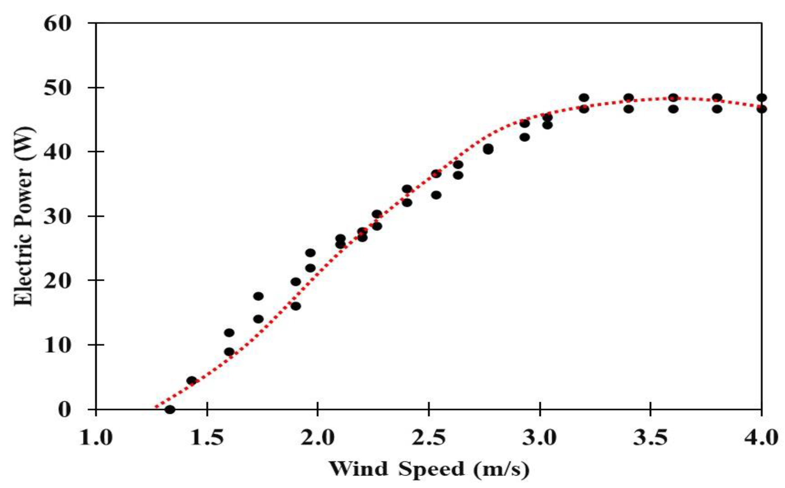
3.5.2. Performance Test of Generator in the Wind Tunnel
3.5.3. Data Analysis
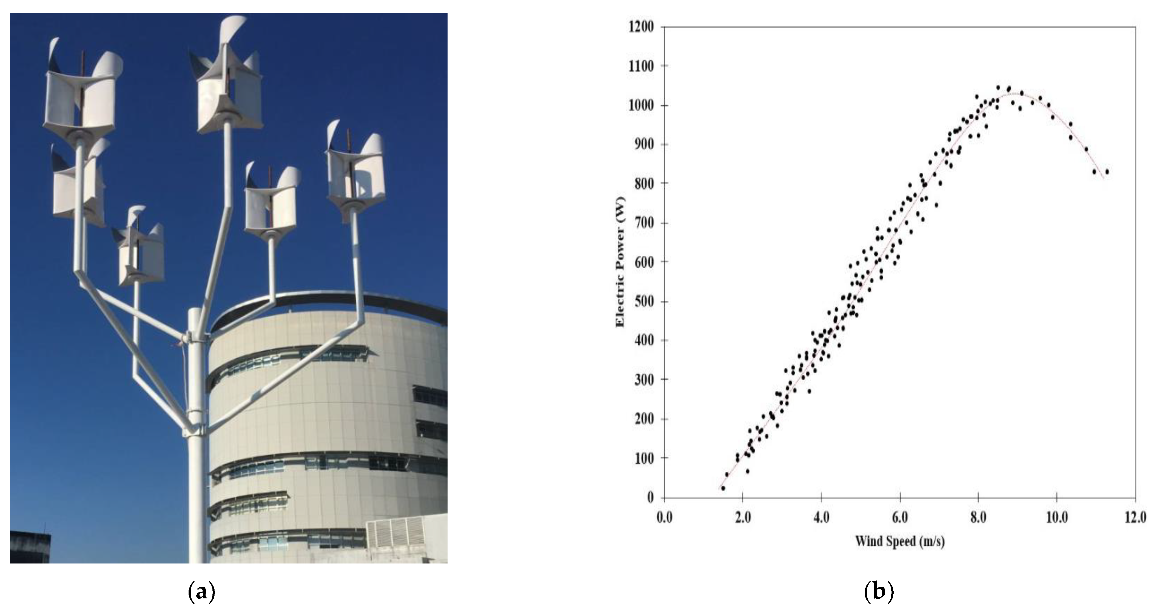
3.5.4. Economic Analysis from Power Curve for the Wind Turbine Generator
4. Conclusions
Author Contributions
Funding
Institutional Review Board Statement
Informed Consent Statement
Data Availability Statement
Acknowledgments
Conflicts of Interest
References
- Ellabban, O.; Abu-Rub, H.; Blaabjerg, F. Renewable Energy Resources: Current Status, Future Prospects and Their Enabling Technology. Renew. Sustain. Energy Rev. 2014, 38, 748–764. [Google Scholar] [CrossRef]
- Cavallo, A.J. Wind Energy: Current Status and Future Prospects. Sci. Glob. Secur. 1993, 4, 65–109. [Google Scholar] [CrossRef]
- Xingjia, Y.; De, T. Design and Manufacturing of Wind Turbine. In Proceedings of the IEEE International Conference on Computer Science and Automation Engineering, Seoul, Korea, 20–24 August 2012. [Google Scholar]
- Mueller-Vahl, H.; Pechlivanoglou, G.; Nayeri, C.; Paschereit, C. Vortex Generators for Wind Turbine Blades: A Combined Wind Tunnel and Wind Turbine Parametric Study. In Turbo Expo: Power for Land, Sea, and Air, Proceedings of the ASME Turbo Expo 2012: Turbine Technical Conference and Exposition, Copenhagen, Denmark, 11–15 June 2012; American Society of Mechanical Engineers Digital Collection: New York, NY, USA, 2013; pp. 899–914. [Google Scholar]
- Bhutta, M.M.A.; Hayat, N.; Farooq, A.U.; Ali, Z.; Jamil, S.R.; Hussain, Z. Vertical Axis Wind Turbine-A Review of Various Configurations and Design Techniques. Renew. Sustain. Energy Rev. 2012, 16, 1926–1939. [Google Scholar] [CrossRef]
- Maeda, T.; Kamada, Y.; Murata, J.; Yamamoto, M.; Ogasawara, T.; Shimizu, K.; Kogaki, T. Study on Power Performance for Straight-Bladed Vertical Axis Wind Turbine by Field and Wind Tunnel Test. Renew. Energy 2016, 90, 291–300. [Google Scholar]
- Ramadan, A.; Yousef, K.; Said, M.; Mohamed, M. Shape Optimization and Experimental Validation of a Drag Vertical Axis Wind Turbine. Energy 2018, 151, 839–853. [Google Scholar] [CrossRef]
- Anup, K.; Whale, J.; Urmee, T. Urban Wind Conditions and Small Wind Turbines in the Built Environment: A Review. Renew. Energy 2019, 131, 268–283. [Google Scholar]
- Battisti, L.; Benini, E.; Brighenti, A.; Dell’Anna, S.; Castelli, M.R. Small Wind Turbine Effectiveness in the Urban Environment. Renew. Energy 2018, 129, 102–113. [Google Scholar]
- Liang, X.; Fu, S.; Ou, B.; Wu, C.; Chao, C.Y.; Pi, K. A Computational Study of the Effects of the Radius Ratio and Attachment Angle on the Performance of a Darrieus-Savonius Combined Wind Turbine. Renew. Energy 2017, 113, 329–334. [Google Scholar] [CrossRef]
- Roy, S.; Saha, U.K. Wind Tunnel Experiments of a Newly Developed Two-Bladed Savonius-Style Wind Turbine. Appl. Energy 2015, 137, 117–125. [Google Scholar] [CrossRef]
- Hashem, I.; Mohamed, M. Aerodynamic Performance Enhancements of H-Rotor Darrieus Wind Turbine. Energy 2018, 142, 531–545. [Google Scholar] [CrossRef]
- Akwa, V.; Vielmo, H.A.; Petry, A.P. A Review on the Performance of Savonius Wind Turbines. Renew. Sustain. Energy Rev. 2012, 16, 3054–3064. [Google Scholar] [CrossRef]
- Tahani, M.; Rabbani, A.; Kasaeian, A.; Mehrpooya, M.; Mirhosseini, M. Design and Numerical Investigation of Savonius Wind Turbine with Discharge Flow Directing Capability. Energy 2017, 130, 327–338. [Google Scholar] [CrossRef]
- Patel, V.; Bhat, G.; Eldho, T.; Prabhu, S. Influence of Overlap Ratio and Aspect Ratio on the Performance of Savonius Hydrokinetic Turbine. Int. J. Energy Res. 2017, 41, 829–844. [Google Scholar] [CrossRef]
- Saha, U.; Rajkumar, M.J. On the Performance Analysis of Savonius Rotor with Twisted Blades. Renew. Energy 2006, 31, 1776–1788. [Google Scholar] [CrossRef]
- Hu, D.; Li, J. Numerical Simulation of Aerodynamic Performance of Wind Turbine Blade Airfoil. Airfoil Renew. Energy Resour. 2011, 29, 6–10. [Google Scholar]
- Pithaksareetham, N.; Hongkarnjanakul, N.; Suchat, S. Eco-Nanocomposites with Epoxidized Natural Rubber for Improved Mechanical Properties Essential to Unmanned Aerial Vehicles Propeller Applications. Adv. Polym. Technol. 2018, 37, 2946–2957. [Google Scholar] [CrossRef]
- Rahmani, H.; Najafi, S.H.M.; Saffarzadeh-Matin, S.; Ashori, A. Mechanical Properties of Carbon Fiber/Epoxy Composites: Effects of Number of Plies, Fiber Contents, and Angle-Ply Layers. Polym. Eng. Sci. 2014, 54, 2676–2682. [Google Scholar] [CrossRef]
- Lanna, A.; Suklueng, M.; Kasagepongsan, C.; Suchat, S. Performance of Novel Engineered Materials from Epoxy Resin with Modified Epoxidized Natural Rubber and Nanocellulose or Nanosilica. Adv. Polym. Technol. 2020, 2020, 2123836. [Google Scholar] [CrossRef]
- Mathew, V.S.; Jyotishkumar, P.; George, S.C.; Gopalakrishnan, P.; Delbreilh, L.; Saiter, J.M.; Saikia, P.J.; Thomas, S. High Performance HTLNR/Epoxy Blend-Phase Morphology and Thermo-Mechanical Properties. J. Appl. Polym. Sci. 2012, 125, 804–811. [Google Scholar] [CrossRef]
- Butta, E.; Levita, G.; Marchetti, A.; Lazzeri, A. Morphology and Mechanical Properties of Amine-Terminated Butadiene-Acrylonitrile/Epoxy Blends. Polym. Eng. Sci. 1986, 26, 63–73. [Google Scholar] [CrossRef]
- Kelly, P. Epoxy Vinyl Ester and Other Resins in Chemical Process Equipment. In Reinforced Plastics Durability; Woodhead Pub.: Sawston, UK, 1999; pp. 282–321. [Google Scholar]
- Guadagno, L.; Vertuccio, L.; Sorrentino, A.; Raimondo, M.; Naddeo, C.; Vittoria, V.; Iannuzzo, G.; Calvi, E.; Russo, S. Mechanical and Barrier Properties of Epoxy Resin Filled with Multi-Walled Carbon Nanotubes. Carbon 2009, 47, 2419–2430. [Google Scholar] [CrossRef]
- Jaiganesh, V.; Manivannan, S. Numerical Analysis and Simulation of Nylon Composite Propeller for Aircraft. Procedia Eng. 2014, 97, 1079–1088. [Google Scholar] [CrossRef] [Green Version]
- Hong, S.-G.; Chan, C.-K. The Curing Behaviors of the Epoxy/Dicyanamide System Modified with Epoxidized Natural Rubber. Thermochim. Acta 2004, 417, 99–106. [Google Scholar] [CrossRef]
- John, K.; Naidu, S.V. Sisal Fiber/Glass Fiber Hybrid Composites: The Impact and Compressive Properties. J. Reinf. Plast. Compos. 2004, 23, 1253–1258. [Google Scholar] [CrossRef]
- Sanjay, M.A.; Yogesha, B. Studies on Mechanical Properties of Jute/E-Glass Fiber Reinforced Epoxy Hybrid Composites. J. Miner. Mater. Charact. Eng. 2016, 4, 15–25. [Google Scholar] [CrossRef] [Green Version]
- Bakar, A.; Ahmad, S.; Kuntjoro, W. Effect of Epoxidized Natural Rubber on Mechanical Properties of Epoxy Reinforced Kenaf Fibre Composites. Pertanika J. Sci. Technol. 2012, 20, 129–137. [Google Scholar]
- Chuayjuljit, S.; Soatthiyanon, N.; Potiyaraj, P. Polymer Blends of Epoxy Resin and Epoxidized Natural Rubber. J. Appl. Polym. Sci. 2006, 102, 452–459. [Google Scholar] [CrossRef]
- Yang, B.; Zhang, J.; Zhou, L.; Lu, M.; Liang, W.; Wang, Z. Effect of Fiber Surface Modification on Water Absorption and Hydrothermal Aging Behaviors of GF/pCBT Composites. Compos. Part B Eng. 2015, 82, 84–91. [Google Scholar] [CrossRef]
- Vismara, M.V.G.; Mello, L.M.d.; di Hipólito, V.; González, A.H.M.; Graeff, C.F.D. Resin Composite Characterizations Following a Simplified Protocol of Accelerated Aging as a Function of the Expiration Date. J. Mech. Behav. Biomed. Mater. 2014, 35, 59–69. [Google Scholar]
- Jakobsen, J.; Jensen, M.; Andreasen, J.H. Thermo-Mechanical Characterisation of In-Plane Properties for CSM E-Glass Epoxy Polymer Composite Materials–Part 1: Thermal and Chemical Strain. Polym. Test. 2013, 32, 1350–1357. [Google Scholar] [CrossRef]
- Barbosa, A.P.C.; Fulco, A.P.P.; Guerra, E.S.; Arakaki, F.K.; Tosatto, M.; Costa, M.C.B.; Melo, J.D.D. Accelerated Aging Effects on Carbon Fiber/Epoxy Composites. Compos. Part B Eng. 2017, 110, 298–306. [Google Scholar] [CrossRef]
- Mlyniec, A.; Korta, J.; Kudelski, R.; Uhl, T. The Influence of the Laminate Thickness, Stacking Sequence and Thermal Aging on the Static and Dynamic Behavior of Car-Bon/Epoxy Composites. Compos. Struct. 2014, 118, 208–216. [Google Scholar] [CrossRef]
- Jakobsen, J.; Jensen, M.; Andreasen, J.H. Thermo-Mechanical Characterisation of In-Plane Properties for CSM E-Glass Epoxy Polymer Composite Materials–Part 2: Young’s Modulus. Polym. Test. 2013, 32, 1417–1422. [Google Scholar] [CrossRef]
- Suchat, S.; Yingprasert, W. ECO-Adhesive from Modified Natural Rubber for Wood Applications. In Advanced Materials Research; Trans Tech Publications: Kapellweg, Switzerland, 2014; pp. 182–185. [Google Scholar]
- Suchat, S.; Lanna, A.; Chotikhun, A.; Hiziroglu, S. Some Properties of Composite Drone Blades from Nanosilica Added Epoxidized Natural Rubber. Polymers 2020, 12, 1293. [Google Scholar] [CrossRef] [PubMed]
- Saz-Orozco, B.D.; Ray, D.; Stanley, W.F. Effect of Thermoplastic Veils on Interlaminar Fracture Toughness of a Glass Fiber/Vinyl Ester Composite. Polym. Compos. 2015, 38, 2501–2508. [Google Scholar] [CrossRef]


| Group Attributed for Peak | Wavenumber (cm−1) | ||
|---|---|---|---|
| Epoxy Resin | ENR 50 | Nanosilica | |
| C–O deformation | 915 | - | - |
| C–H stretching | 3057 | - | - |
| C=C–H stretching and deformation | - | 837, 1588 | - |
| C–O stretching of oxyran ring | - | 873 | - |
| H-O-H stretching mode of the absorbed water | - | - | 3340, 1645 |
| Si-O-Si asymmetric bond | - | - | 1093, 788 |
| Si-O-Si bond bending vibration | - | - | 466 |
| Nanosilica (phr) | Impact Strength (kJ/m2) | Tensile Strength (MPa) | Hardness (Shore D) | Density (g/cm3) |
|---|---|---|---|---|
| 0 | 11.05 ± 0.28 c | 27.45 ± 0.34 e | 78.50 ± 0.54 b | 0.98 ± 0.10 c |
| 1 | 11.42 ± 0.52 c | 40.43 ± 0.47 c | 78.60 ± 0.03 b | 1.02 ± 0.05 b |
| 2 | 11.85 ±1.30 c | 41.85 ± 0.14 b | 78.70 ± 0.83 b | 1.05 ± 0.15 b |
| 3 | 15.30 ± 0.45 a | 43.50 ± 0.94 a | 80.10 ± 0.71 a | 1.10 ± 0.10 a |
| 4 | 13.25 ± 1.15 b | 38.43 ± 0.92 d | 81.20 ± 0.53 a | 1.11 ± 0.05 a |
| 5 | 9.50 ± 1.06 d | 27.57 ± 0.82 e | 81.40 ± 0.49 a | 1.14 ± 0.01 a |
| Part | Function | Materials Used |
|---|---|---|
| Wind blade shell | Maintaining the blade shape, resisting the wind and gravitational forces | Strong, lightweight composites (Glass fiber + epoxy resin) |
| Adhesive layers between composite plies, and the web and the blade shell | Ensuring the cut-off plane strength and stiffness of the blade | Strong and highly adhesive nanocomposites (Epoxy resin + ENR 50 + nanosilica) |
| Supported parts of the shell | Resisting the buckling load | Thickened sandwich structures with light core materials and multidirectional face laminates |
| No. | Parameter | Value |
|---|---|---|
| 1 | Wind turbine of types | Tree shaped wind turbines (TSWT) |
| 2 | Rotor of blade (radius × length) | 0.4 × 1 m |
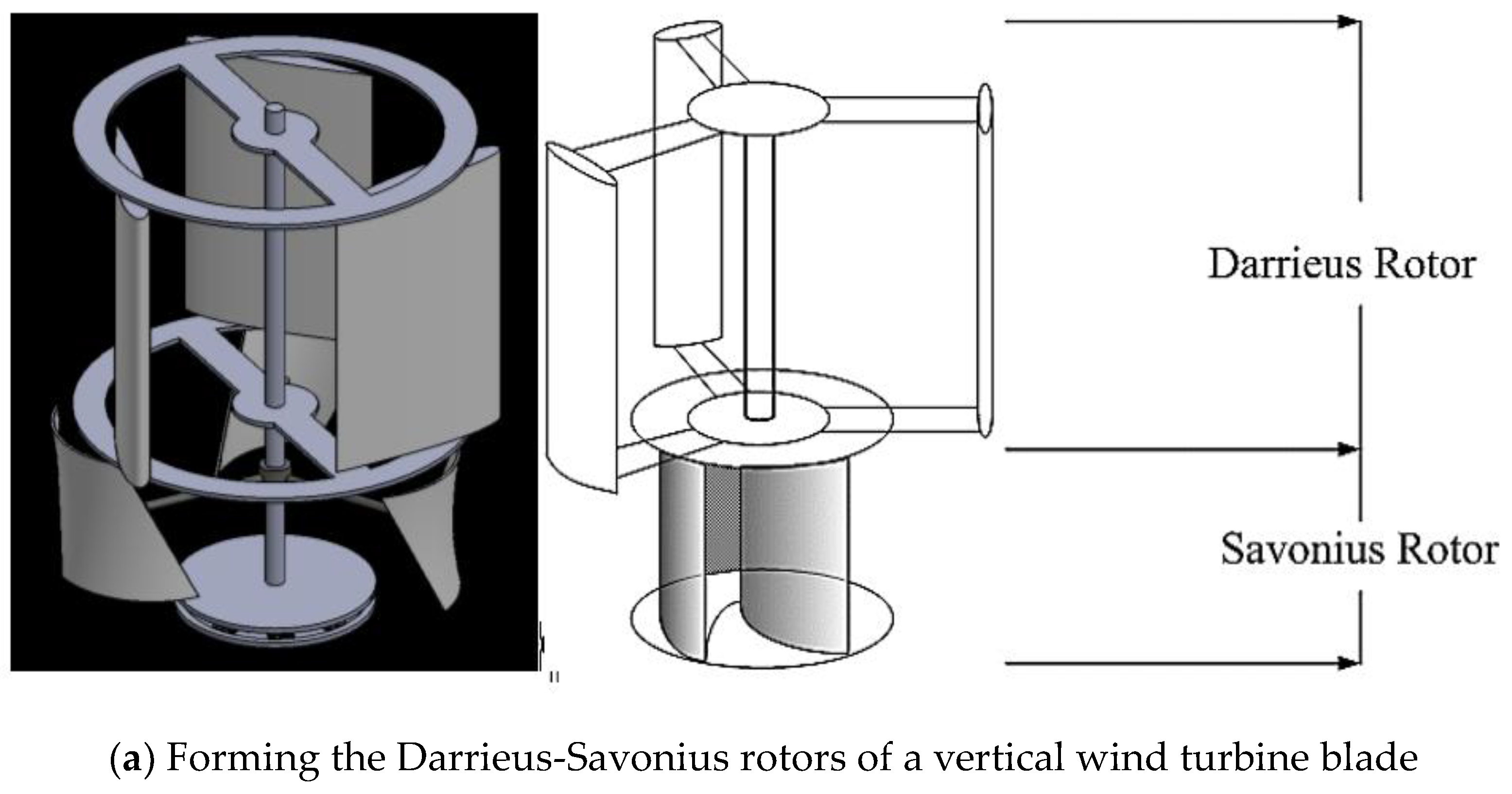
| 3 | Blade of type | Hybrid Savonius-Darrieus |
| 4 | Blade material | Glass fiber reinforced nanocomposite |
| 5 | Number of blades | 3 × 6 |
| 6 | Cut-in wind speed | 1.2 m/s |
| 7 | Cut-off wind speed | 8.5 m/s |
| 8 | Rate wind speed | 6–8 m/s |
| 9 | Rate power | 1 kW |
| 10 | Height of tower (m) | 8 m (the tree shaped) |
| 11 | Electrical generator | Axial flux permanent magnet generator (AFPMG) |
| 12 | Number of copper coil | 20#SWG |
| 13 | Phase number | 3 phases |
| 14 | Pole number | 8 poles |
Publisher’s Note: MDPI stays neutral with regard to jurisdictional claims in published maps and institutional affiliations. |
© 2021 by the authors. Licensee MDPI, Basel, Switzerland. This article is an open access article distributed under the terms and conditions of the Creative Commons Attribution (CC BY) license (https://creativecommons.org/licenses/by/4.0/).
Share and Cite
Kasagepongsan, C.; Suchat, S. Novel Engineered Materials: Epoxy Resin Nanocomposite Reinforced with Modified Epoxidized Natural Rubber and Fibers for Low Speed Wind Turbine Blades. Polymers 2021, 13, 2761. https://0-doi-org.brum.beds.ac.uk/10.3390/polym13162761
Kasagepongsan C, Suchat S. Novel Engineered Materials: Epoxy Resin Nanocomposite Reinforced with Modified Epoxidized Natural Rubber and Fibers for Low Speed Wind Turbine Blades. Polymers. 2021; 13(16):2761. https://0-doi-org.brum.beds.ac.uk/10.3390/polym13162761
Chicago/Turabian StyleKasagepongsan, Chainuson, and Sunisa Suchat. 2021. "Novel Engineered Materials: Epoxy Resin Nanocomposite Reinforced with Modified Epoxidized Natural Rubber and Fibers for Low Speed Wind Turbine Blades" Polymers 13, no. 16: 2761. https://0-doi-org.brum.beds.ac.uk/10.3390/polym13162761