
Mechanical Properties of Flexible TPU-Based 3D Printed Lattice Structures: Role of Lattice Cut Direction and Architecture

 , , ,
, , , 
Abstract
:1. Introduction
2. Experimental Section
2.1. Materials and Processing
2.2. Characterization
3. Results and Discussion
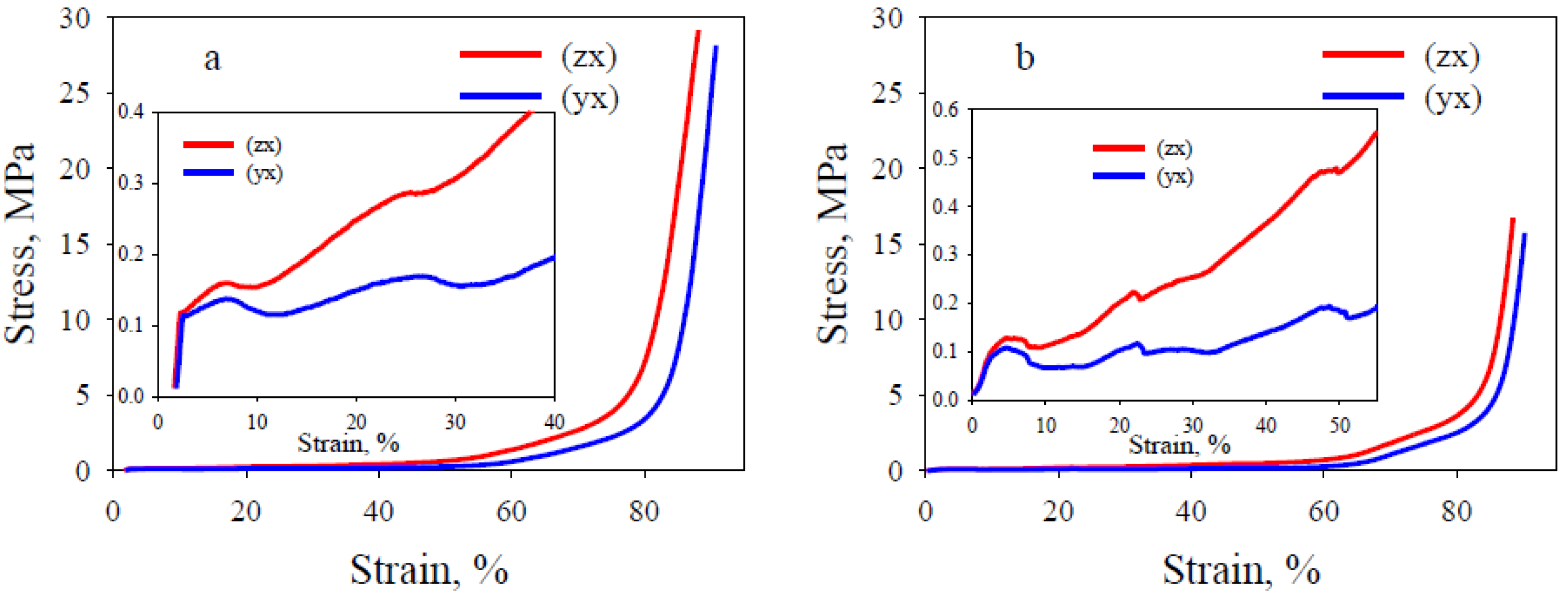
3.1. Tensile and Static Three-Point Bending Tests
3.2. DMA and DSC Analyzes
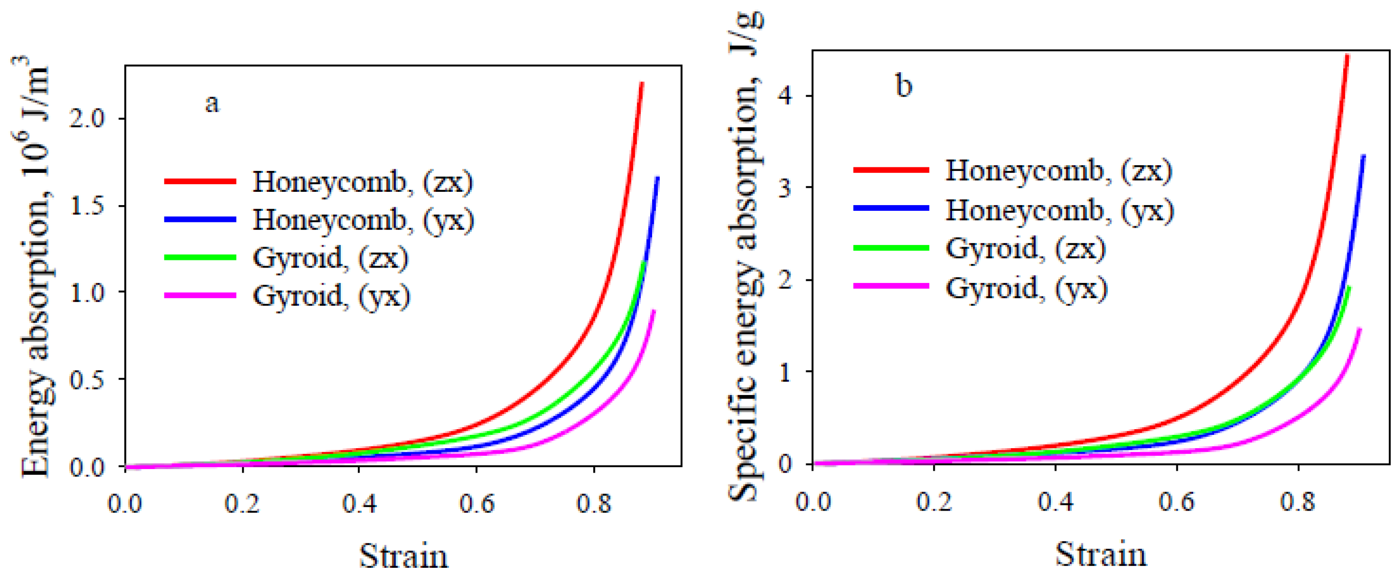
3.3. Compression Test
4. Conclusions
Supplementary Materials
Author Contributions
Funding
Data Availability Statement
Acknowledgments
Conflicts of Interest
References
- Bai, L.; Gong, C.; Chen, X.; Sun, Y.; Xin, L.; Pu, H.; Peng, Y.; Jun Luo, J. Mechanical properties and energy absorption capabilities of functionally graded lattice structures: Experiments and simulations. Int. J. Mech. Sci. 2000, 182, 105735. [Google Scholar] [CrossRef]
- Yan, C.; Hao, L.; Hussein, A.; Bubb, S.L.; Young, P.; Raymont, D. Evaluation of light-weight AlSi10Mg periodic cellular lattice structures fabricated via direct metal laser sintering. J. Mater. Proc. Techn. 2014, 214, 856–864. [Google Scholar] [CrossRef]
- Yan, C.; Hao, L.; Hussein, A.; Young, P.; Raymont, D. Advanced lightweight 316L stainless steel cellular lattice structures fabricated via selective laser melting. Mater. Des. 2014, 55, 533–541. [Google Scholar] [CrossRef] [Green Version]
- Li, Y.; Gu, D. Parametric analysis of thermal behavior during selective laser melting additive manufacturing of aluminum alloy powder. Mater. Des. 2014, 63, 856–867. [Google Scholar] [CrossRef]
- Hakamada, M.; Kuromura, T.; Chen, Y.; Kusuda, H.; Mabuchi, M. High sound absorption of porous aluminum fabricated by spacer method. Appl. Phys. Lett. 2006, 88, 254106. [Google Scholar] [CrossRef]
- Hakamada, M.; Kuromura, T.; Chen, Y.; Kusuda, H.; Mabuchi, M. Sound absorption characteristics of porous aluminum fabricated by spacer method. J. Appl. Phys. 2006, 100, 114908. [Google Scholar] [CrossRef]
- Levy, D.; Shirizly, A.; Rittel, D. Static and dynamic compressive response of additively manufactured discrete patterns of Ti6Al4V. Int. J. Impact Eng. 2018, 122, 1225. [Google Scholar] [CrossRef]
- Bidan, C.M.; Wang, F.M.; Dunlop, J.W.C. A three-dimensional model for tissue deposition on complex surfaces. Comp. Meth. Biomech. Biomed. Eng. 2013, 16, 1056–1070. [Google Scholar] [CrossRef]
- Bidan, C.M.; Kommareddy, K.P.; Rumpler, M.; Kollmannsberger, P.; Brechet, Y.J.M.; Fratzl, P.; Dunlop, J.W.C. How linear tension converts to curvature: Geometric control of bone tissue growth. PLoS ONE 2012, 7, 36336. [Google Scholar] [CrossRef] [PubMed] [Green Version]
- Markkula, S.; Storck, S.; Burns, D.; Zupan, M. Compressive Behavior of pyramidal, tetrahedral, and strut-reinforced tetrahedral ABS and electroplated cellular solids. Adv. Eng. Mater. 2009, 11, 56–62. [Google Scholar] [CrossRef]
- Jiang, J.; Xiong, Y.; Zhang, Z.; Rosen, D. Machine learning integrated design for additive manufacturing. J. Intell. Manuf. 2020, 31, 865–884. [Google Scholar]
- Silva, R.G.; Estay, C.S.; Pavez, G.M.; Viñuela, J.Z.; Torres, M.J. Influence of Geometric and Manufacturing Parameters on the Compressive Behavior of 3D Printed Polymer Lattice Structures. Materials 2021, 14, 1462. [Google Scholar] [CrossRef]
- Nazir, A.; Abate, K.M.; Kumar, A.; Jeng, J.Y. A state-of-the-art review on types, design, optimization, and additive manufacturing of cellular structures. Int. J. Adv. Manuf. Technol. 2019, 104, 3489–3510. [Google Scholar] [CrossRef]
- Zaharia, S.M.; Enescu, L.A.; Pop, M.A. Mechanical Performances of lightweight sandwich structures produced by material extrusion-based additive manufacturing. Polymers 2020, 12, 1740. [Google Scholar] [CrossRef]
- Gautam, R.; Idapalapati, S.; Feih, S. Printing and characterization of kagome lattice structures by fused deposition modelling. Mater. Des. 2018, 137, 266–275. [Google Scholar] [CrossRef]
- Ye, G.; Bi., H.; Chen, L.; Hu, Y. Compression and energy absorption performances of 3D printed polylactic acid lattice core sandwich structures. 3D Print. Additive Manuf. 2019, 6, 333–343. [Google Scholar] [CrossRef]
- Płatek, P.; Rajkowski, K.; Cieplak, K.; Sarzyński, M.; Małachowski, J.; Woźniak, R.; Janiszewski, J. Deformation process of 3D printed structures made from flexible material with different values of relative density. Polymers 2020, 12, 2120. [Google Scholar] [CrossRef]
- Bakradze, G.; Arajs, E.; Gaidukovs, S.; Vijay Kumar Thakur, V.K. On the heuristic procedure to determine processing parameters in additive manufacturing based on materials extrusion. Polymers 2020, 12, 3009. [Google Scholar] [CrossRef] [PubMed]
- Zhang, J.Z.; Peng, X.Y.; Liu, S.; Jiang, B.P.; Ji, S.C.; Shen, X.C. The Persistence Length of Semiflexible Polymers in Lattice Monte Carlo Simulations. Polymers 2019, 11, 295. [Google Scholar] [CrossRef] [PubMed] [Green Version]
- Ge, C.; Priyadarshini, L.; Cormier, D.; Pan, L.; Tuber, J. A preliminary study of cushion properties of a 3D printed thermoplastic polyurethane Kelvin foam. Packag. Technol. Sci. 2018, 31, 361–368. [Google Scholar] [CrossRef]
- Bates, S.R.G.; Farrow, I.R.; Trask, R.S. 3D printed polyurethane honeycombs for repeated tailored energy absorption. Mater. Des. 2016, 112, 172–183. [Google Scholar] [CrossRef] [Green Version]
- Bates, S.R.; Farrow, I.R.; Trask, R.S. 3D printed elastic honeycombs with graded density for tailorable energy absorption. Active and Passive Smart Structures and Integrated Systems 2016. In Proceedings of the 2016 International Society for Optics and Photonics; Society of Photo-Optical Instrumentation Engineers (SPIE), San Diego, CA, USA, 28 August–1 September 2016. [Google Scholar]
- Bates, S.R.; Farrow, I.R.; Trask, R.S. Compressive behavior of 3D printed thermoplastic polyurethane honeycombs with graded densities. Mater. Des. 2019, 162, 130–142. [Google Scholar] [CrossRef]
- Townsend, S.; Adams, R.; Robinson, M.; Hanna, B.; Theobald, P. 3D printed origami honeycombs with tailored out-of-plane energy absorption behavior. Mater. Des. 2020, 195, 108930. [Google Scholar] [CrossRef]
- Xu, T.; Shen, W.; Lin, X.; Xie, Y.M. Mechanical properties of additively manufactured thermoplastic polyurethane (TPU) material affected by various processing parameters. Polymers 2020, 12, 3010. [Google Scholar] [CrossRef]
- Beloshenko, V.; Beygelzimer, Y.; Chishko, V.; Savchenko, B.; Sova, N.; Verbylo, D.; Vozniak, I. Mechanical Properties of Thermoplastic Polyurethane-Based Three-Dimensional-Printed Lattice Structures: Role of Build Orientation, Loading Direction, and Filler. Available online: https://www.liebertpub.com/doi/10.1089/3dp.2021.0031 (accessed on 14 May 2021).
- Rodríguez-Parada, L.; Rosa, S.; Mayuet, P.F. Influence of 3D-printed TPU properties for the design of elastic products. Polymers 2021, 13, 2519. [Google Scholar] [CrossRef] [PubMed]
- Vu, C.C.; Nguyen, T.T.; Kim, S.; Kim, J. Effects of 3D printing-line directions for stretchable sensor performances. Materials 2021, 14, 1791. [Google Scholar] [CrossRef] [PubMed]
- Kwon, J.; Ock, J.; Kim, N. Mimicking the mechanical properties of aortic tissue with pattern-embedded 3D printing for a realistic phantom. Materials 2020, 13, 5042. [Google Scholar] [CrossRef] [PubMed]
- Wang, J.; Yang, B.; Lin, X.; Gao, L.; Liu, T.; Lu, Y.; Wang, R. Research of TPU materials for 3D printing aiming at non-pneumatic tires by FDM method. Polymers 2020, 12, 2492. [Google Scholar] [CrossRef]
- Haryńska, A.; Carayon, I.; Kosmela, P.; Brillowska-Dąbrowska, A.; Łapiński, M.; Kucińska-Lipka, J.; Janik, H. Processing of polyester-urethane filament and characterization of FFF 3D printed elastic porous structures with potential in cancellous bone tissue engineering. Materials 2020, 13, 4457. [Google Scholar] [CrossRef]
- Andrews, E.W.; Gioux, G.; Onck, P.; Gibson, L.J. Size effects in ductile cellular solids. Part II: Experimental results. Int. J. Mech. Sci. 2001, 43, 701–713. [Google Scholar] [CrossRef] [Green Version]
- Pham, A.; Kelly, C.; Gall, K. Free boundary effects and representative volume elements in 3D printed Ti–6Al–4V gyroid structures. J. Mater. Res. 2020, 35, 2547–2555. [Google Scholar] [CrossRef]
- Yoder, M.; Thompson, L.; Summers, J. Size effects in lattice structures and a comparison to micropolar elasticity. Inter. J. Solid. Struct. 2018, 143, 245–261. [Google Scholar] [CrossRef]
- Kopal, I.; Harničárová, M.; Valíček, J.; Kušnerová, M. Modeling the temperature dependence of dynamic mechanical properties and visco-elastic behavior of thermoplastic polyurethane using artificial neural network. Polymers 2017, 9, 519. [Google Scholar] [CrossRef] [PubMed] [Green Version]


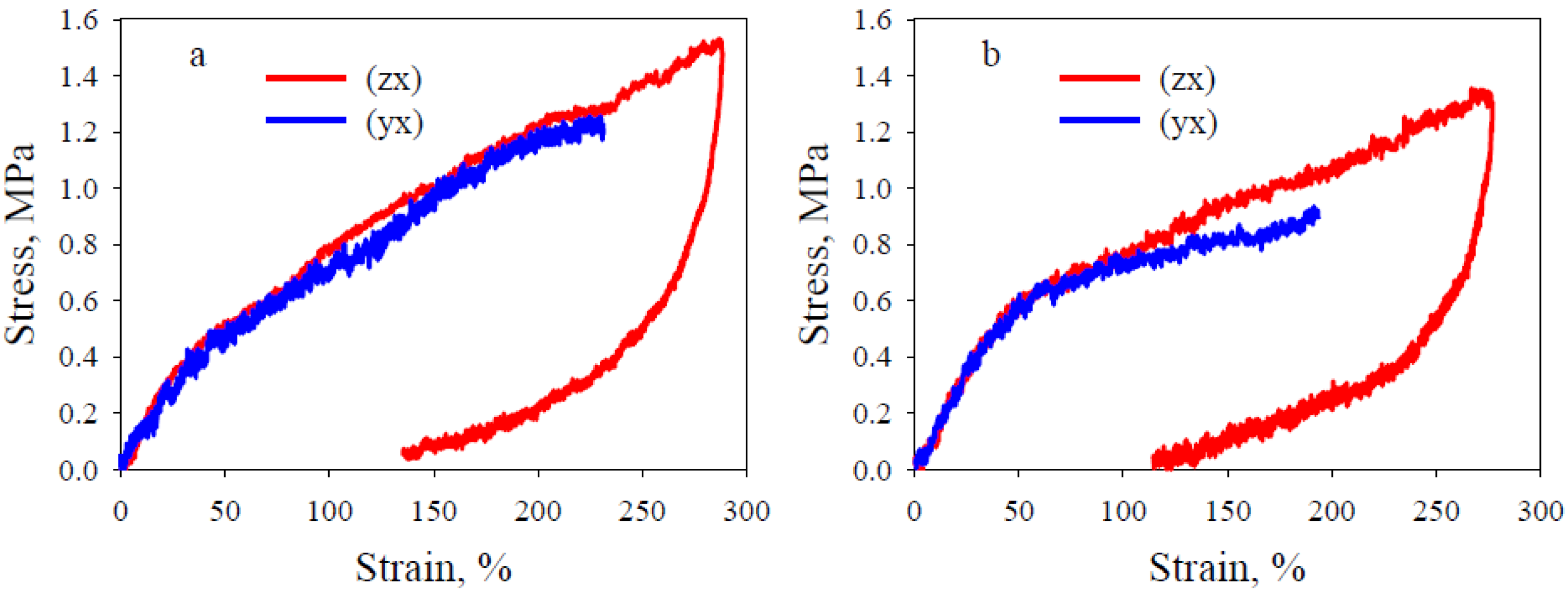
| Internal Architecture | Sample Orientation | E, MPa | σT, MPa | εb, % | εr, % |
|---|---|---|---|---|---|
| Honeycomb | (zx) | 2.1 ± 0.1 | Not break | >280 | 46 ± 2 |
| (yx) | 1.6 ± 0.1 | 1.26 ± 0.05 | 230 ± 5 | 21 ± 2 | |
| Gyroid | (zx) | 1.5 ± 0.1 | Not break | >280 | 31 ± 2 |
| (yx) | 1.4 ± 0.1 | 0.94 ± 0.05 | 190 ± 6 | 12 ± 1 |
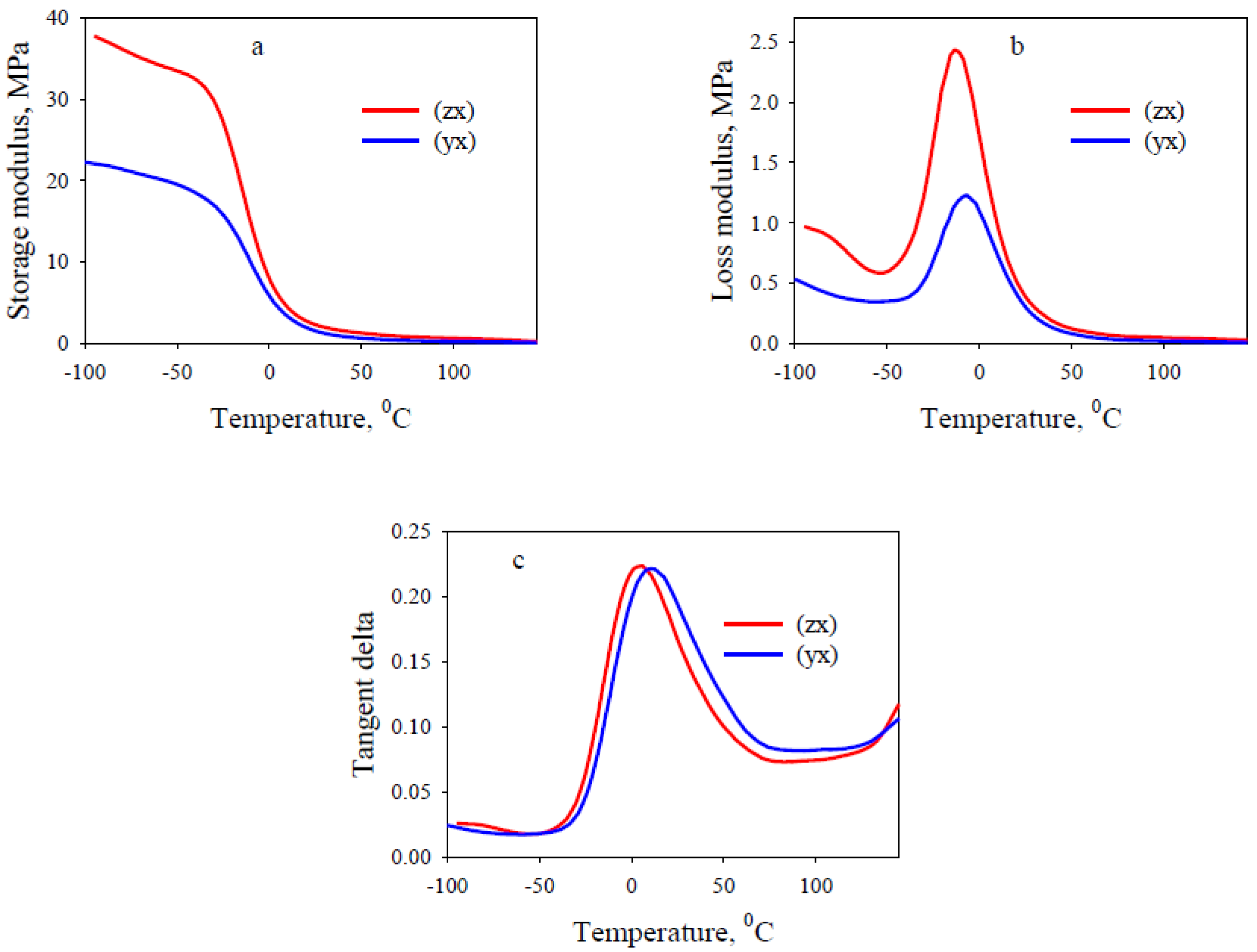
| Internal Architecture | Sample Orientation | E’, MPa | E’’, MPa | E’’m, MPa | TE, °C | Ttgδ, °C | tgδ | tgδm |
|---|---|---|---|---|---|---|---|---|
| Honeycomb | (zx) | 2.5 | 0.40 | 2.6 | −13 | 7 | 0.18 | 0.23 |
| (yx) | 1.7 | 0.35 | 1.4 | −11 | 6 | 0.19 | 0.23 | |
| Gyroid | (zx) | 0.7 | 0.16 | 1.1 | −12 | 6 | 0.2 | 0.27 |
| (yx) | 0.8 | 0.15 | 0.85 | −11 | 5 | 0.2 | 0.25 |
| Internal Architecture | Sample Orientation | E, MPa | σL, MPa | εy, % | εD, % |
|---|---|---|---|---|---|
| Honeycomb | (zx) | 10.8 ± 0.3 | 4.5 ± 0.2 | 1.6 ± 0.1 | 79 ± 3 |
| (yx) | 10.7 ± 0.2 | 4.3 ± 0.1 | 1.4 ± 0.1 | 84 ± 4 | |
| Gyroid | (zx) | 7.5 ± 0.3 | 4.1 ± 0.1 | 1.3 ± 0.1 | 83 ± 3 |
| (yx) | 7.3 ± 0.3 | 4.0 ± 0.1 | 1.1 ± 0.2 | 86 ± 3 |
Publisher’s Note: MDPI stays neutral with regard to jurisdictional claims in published maps and institutional affiliations. |
© 2021 by the authors. Licensee MDPI, Basel, Switzerland. This article is an open access article distributed under the terms and conditions of the Creative Commons Attribution (CC BY) license (https://creativecommons.org/licenses/by/4.0/).
Share and Cite
Beloshenko, V.; Beygelzimer, Y.; Chishko, V.; Savchenko, B.; Sova, N.; Verbylo, D.; Voznyak, A.; Vozniak, I. Mechanical Properties of Flexible TPU-Based 3D Printed Lattice Structures: Role of Lattice Cut Direction and Architecture. Polymers 2021, 13, 2986. https://0-doi-org.brum.beds.ac.uk/10.3390/polym13172986
Beloshenko V, Beygelzimer Y, Chishko V, Savchenko B, Sova N, Verbylo D, Voznyak A, Vozniak I. Mechanical Properties of Flexible TPU-Based 3D Printed Lattice Structures: Role of Lattice Cut Direction and Architecture. Polymers. 2021; 13(17):2986. https://0-doi-org.brum.beds.ac.uk/10.3390/polym13172986
Chicago/Turabian StyleBeloshenko, Victor, Yan Beygelzimer, Vyacheslav Chishko, Bogdan Savchenko, Nadiya Sova, Dmytro Verbylo, Andrei Voznyak, and Iurii Vozniak. 2021. "Mechanical Properties of Flexible TPU-Based 3D Printed Lattice Structures: Role of Lattice Cut Direction and Architecture" Polymers 13, no. 17: 2986. https://0-doi-org.brum.beds.ac.uk/10.3390/polym13172986