
Effects of Groove Sealing of the Posterior Occlusal Surface and Offset of the Internal Surface on the Internal Fit and Accuracy of Implant Placements Using 3D-Printed Surgical Guides: An In Vitro Study

 , and
, and 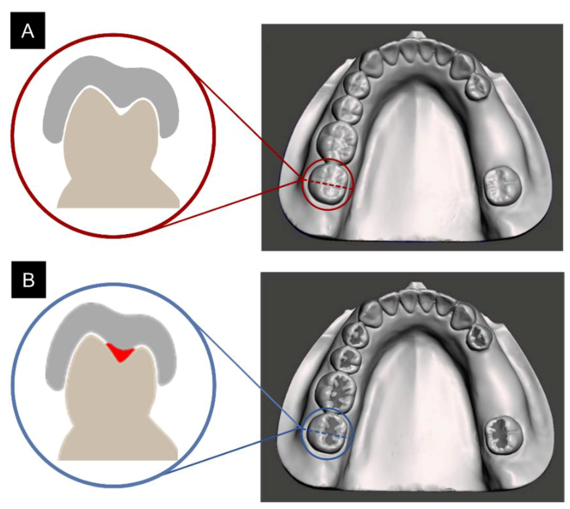
Abstract
:1. Introduction
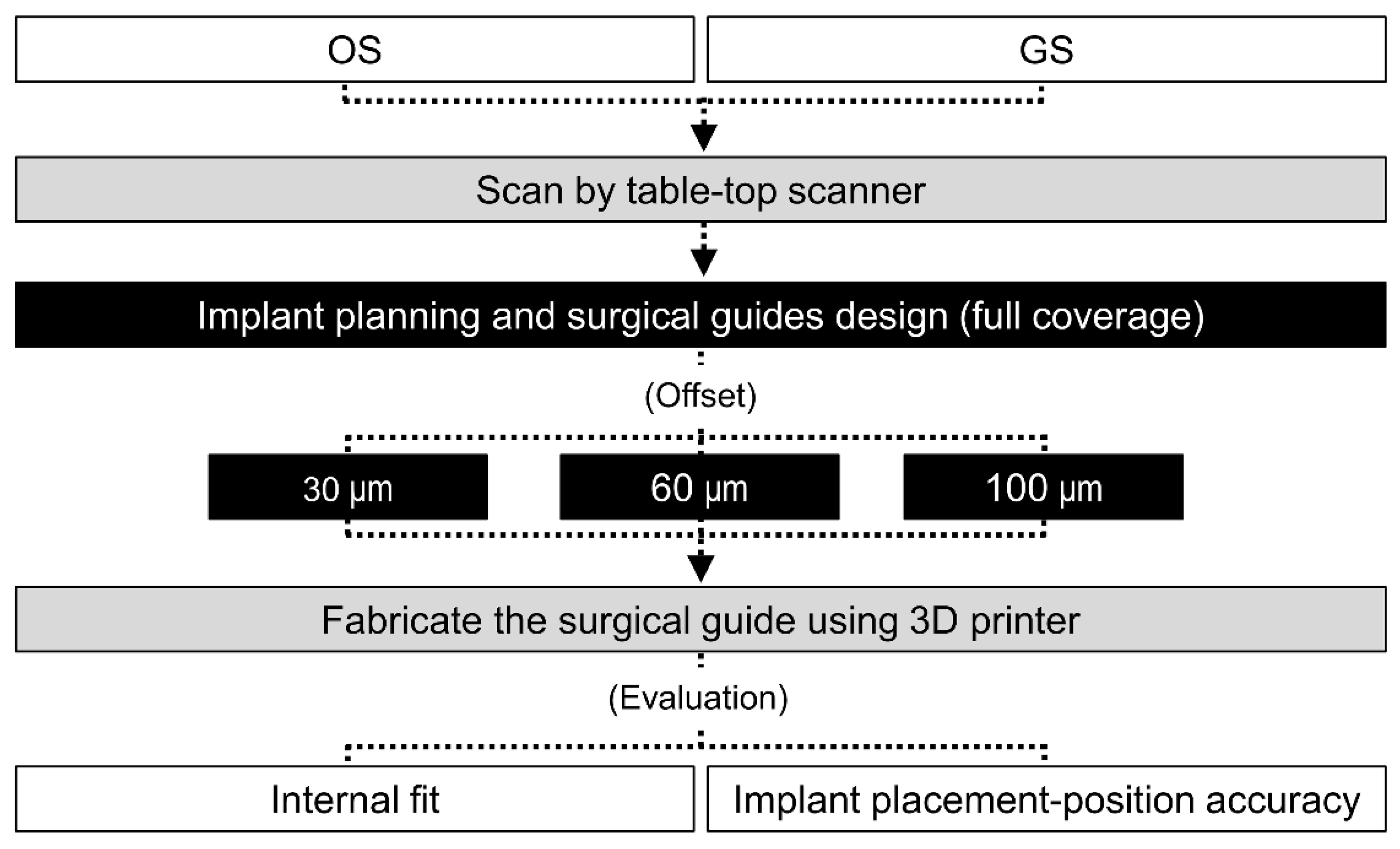
2. Materials and Methods
2.1. Preparation of the Experimental Model
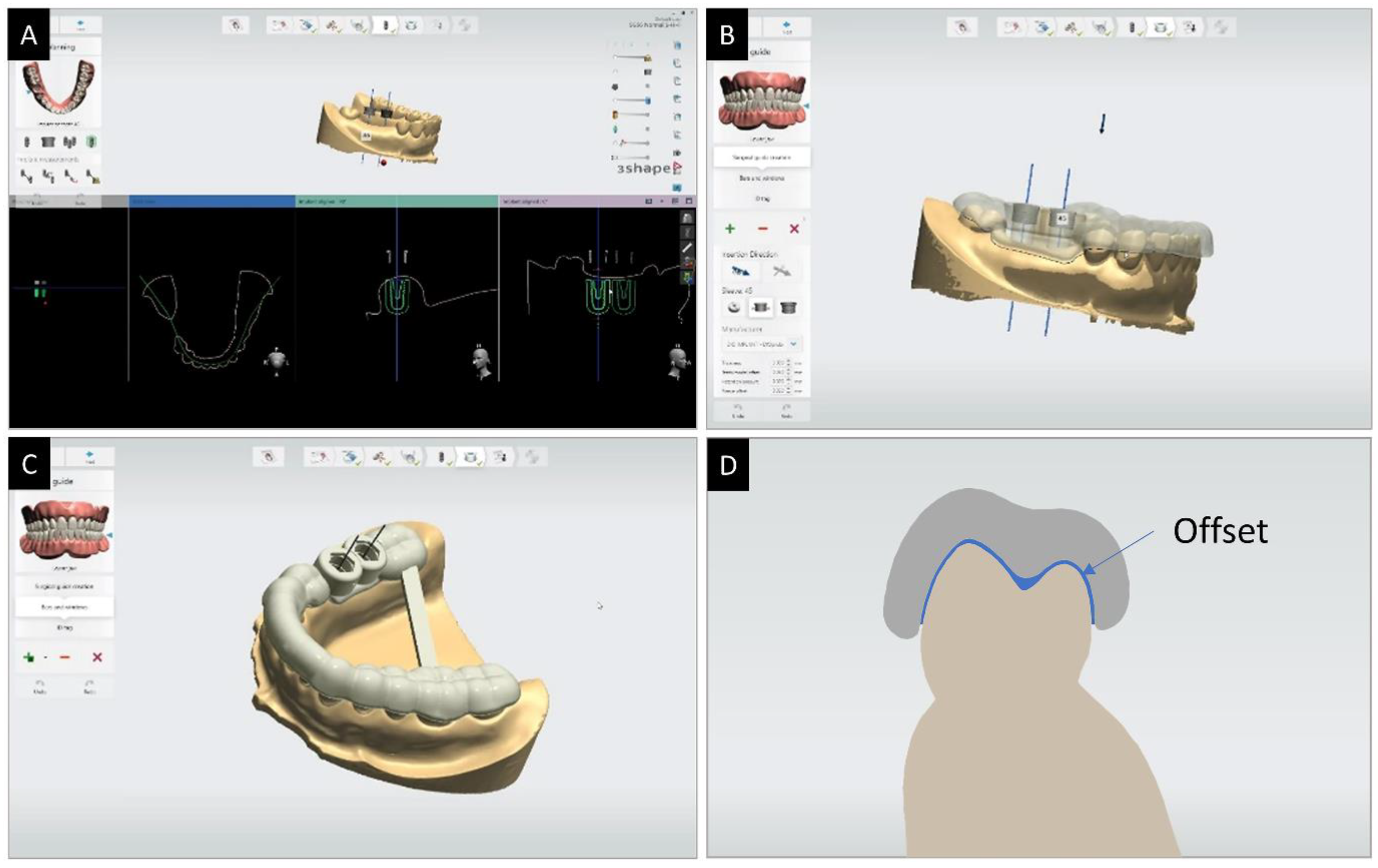
2.2. Design and Production of Surgical Guides
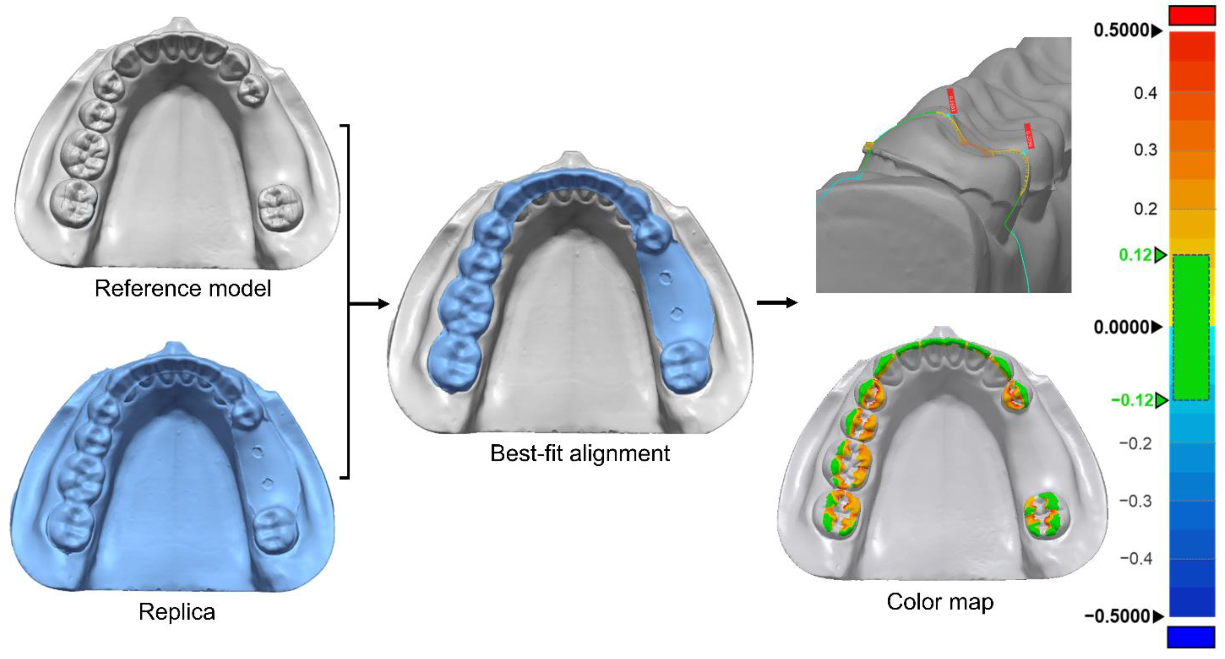
2.3. Evaluation of Surgical Guide Internal Fit
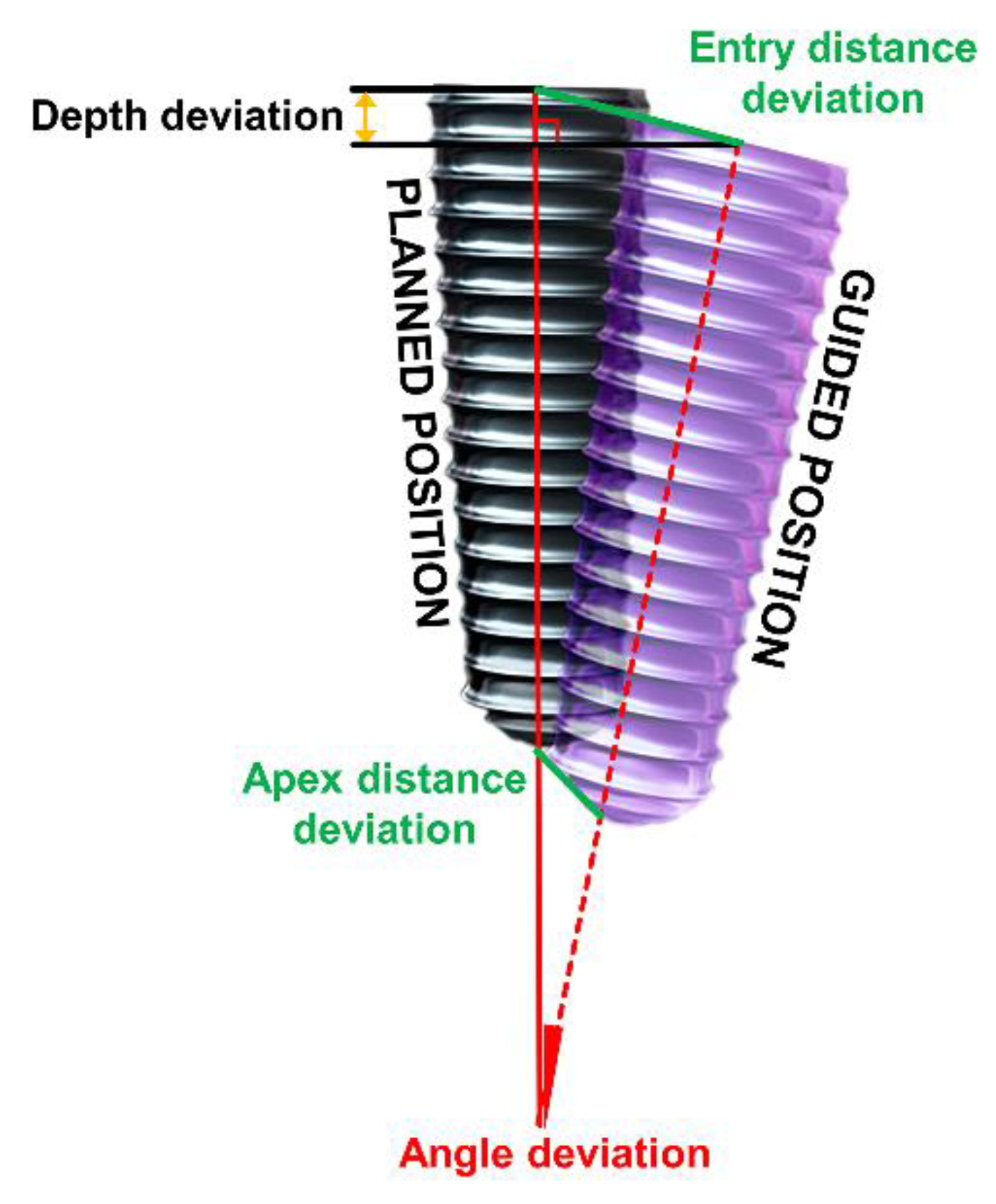
2.4. Evaluation of Implant Placement Position
2.5. Statistical Analysis
3. Results
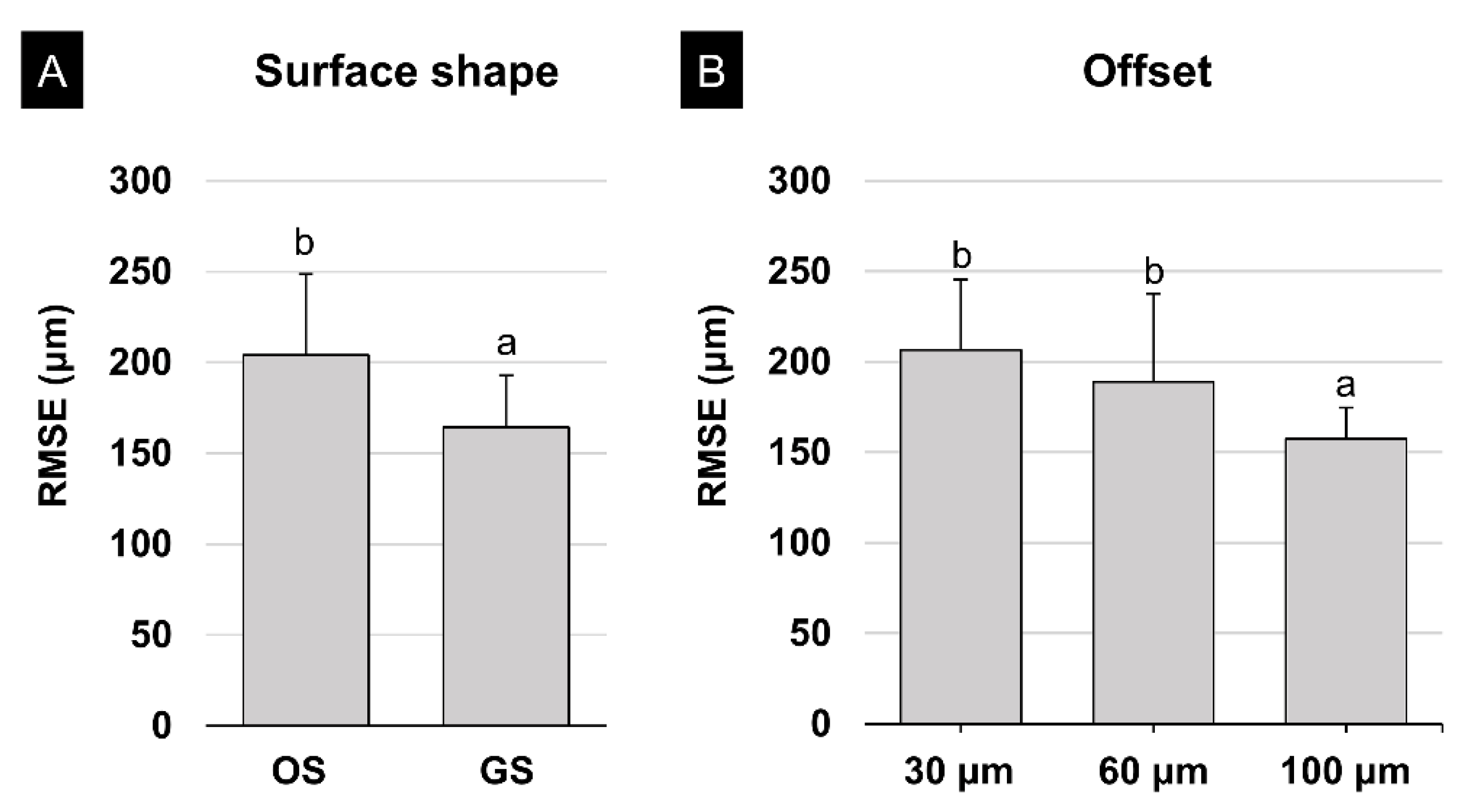
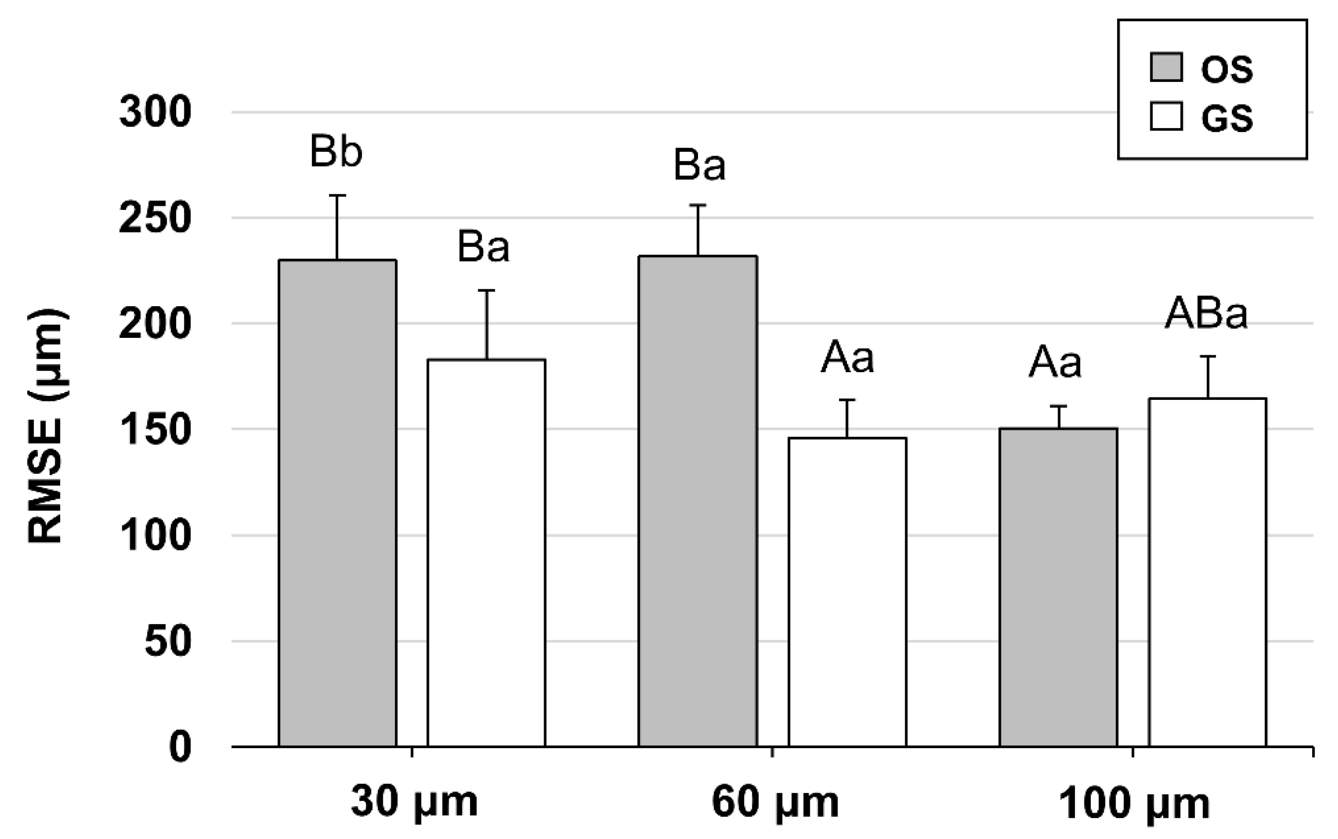
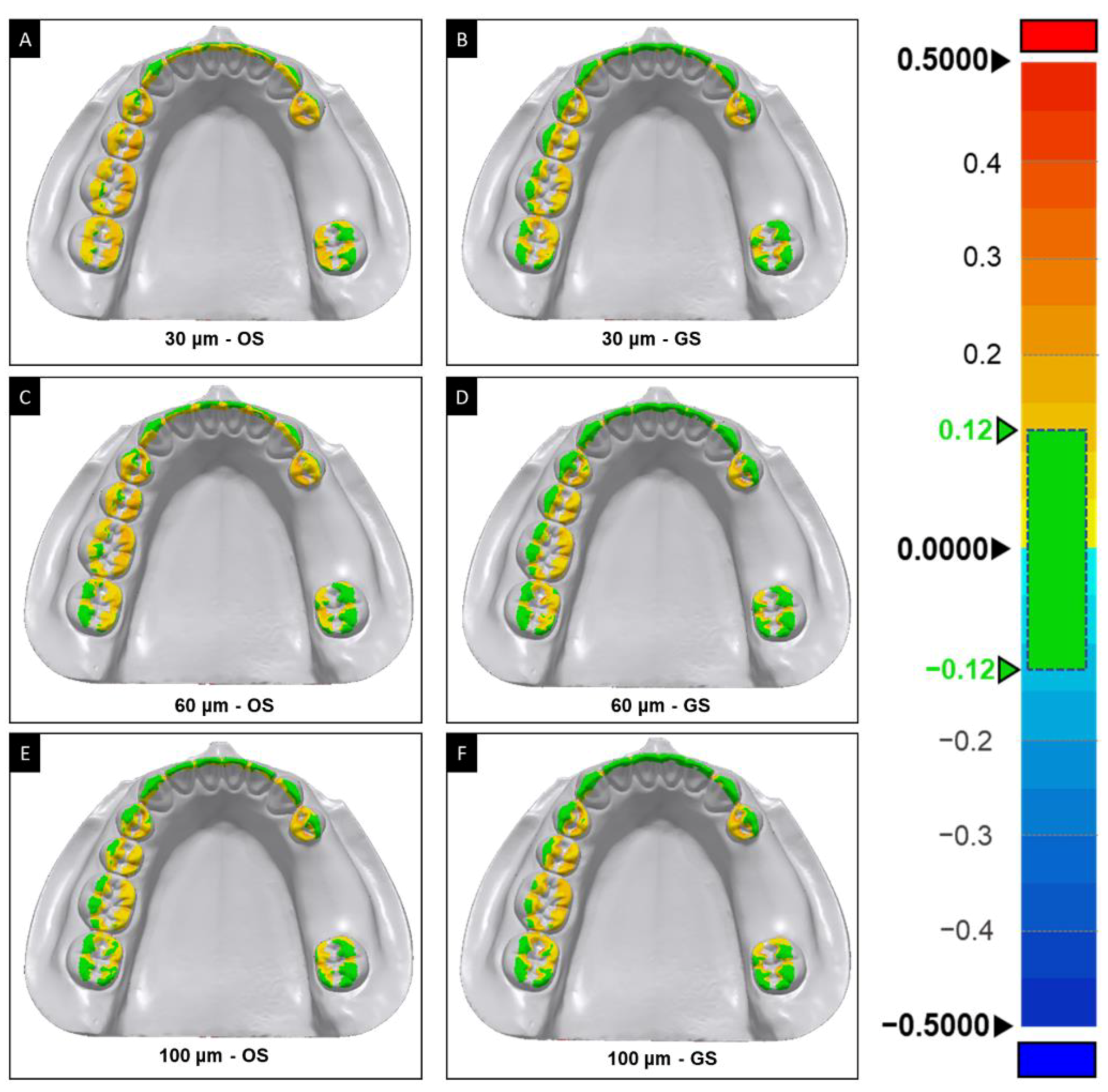
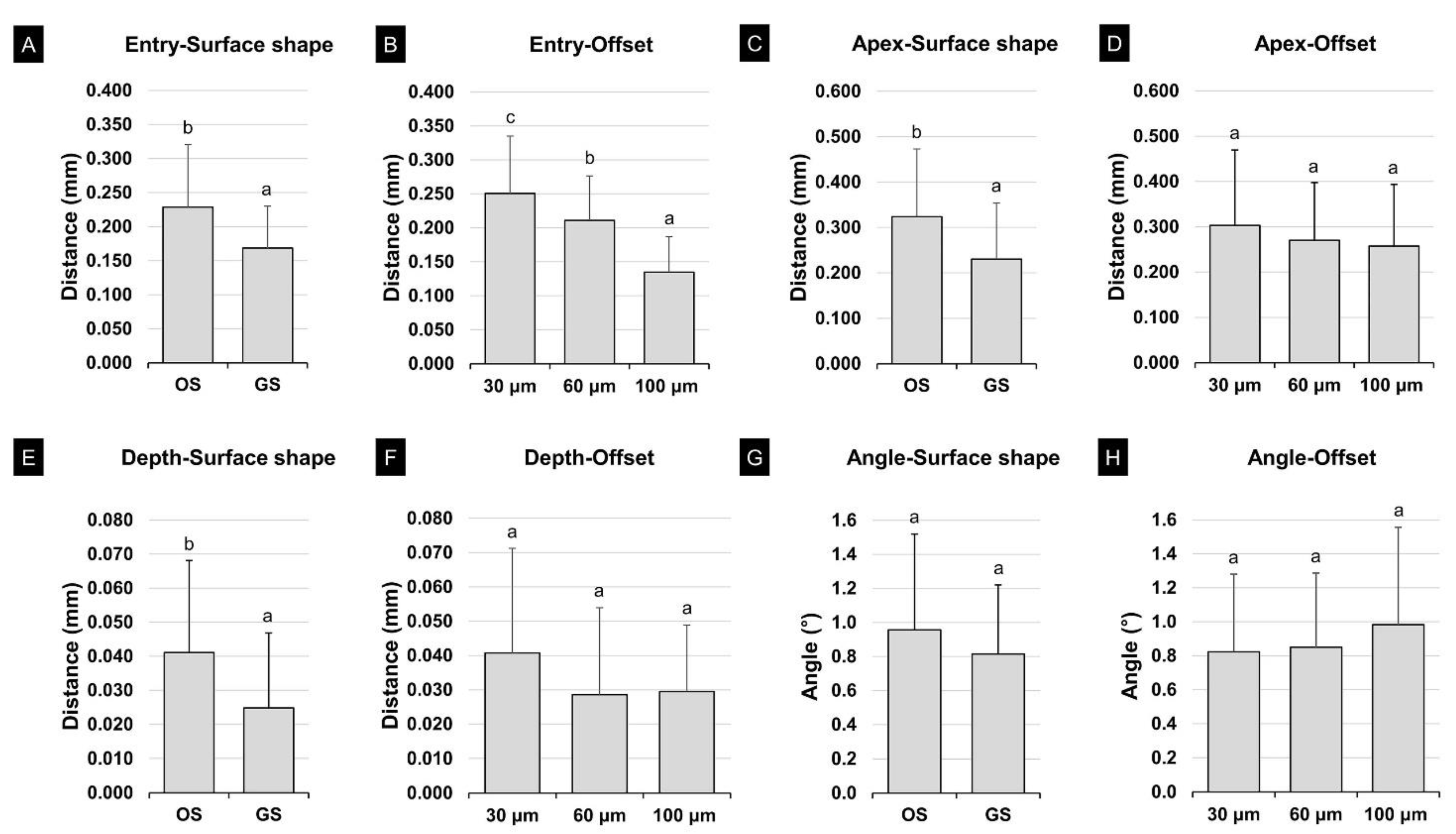
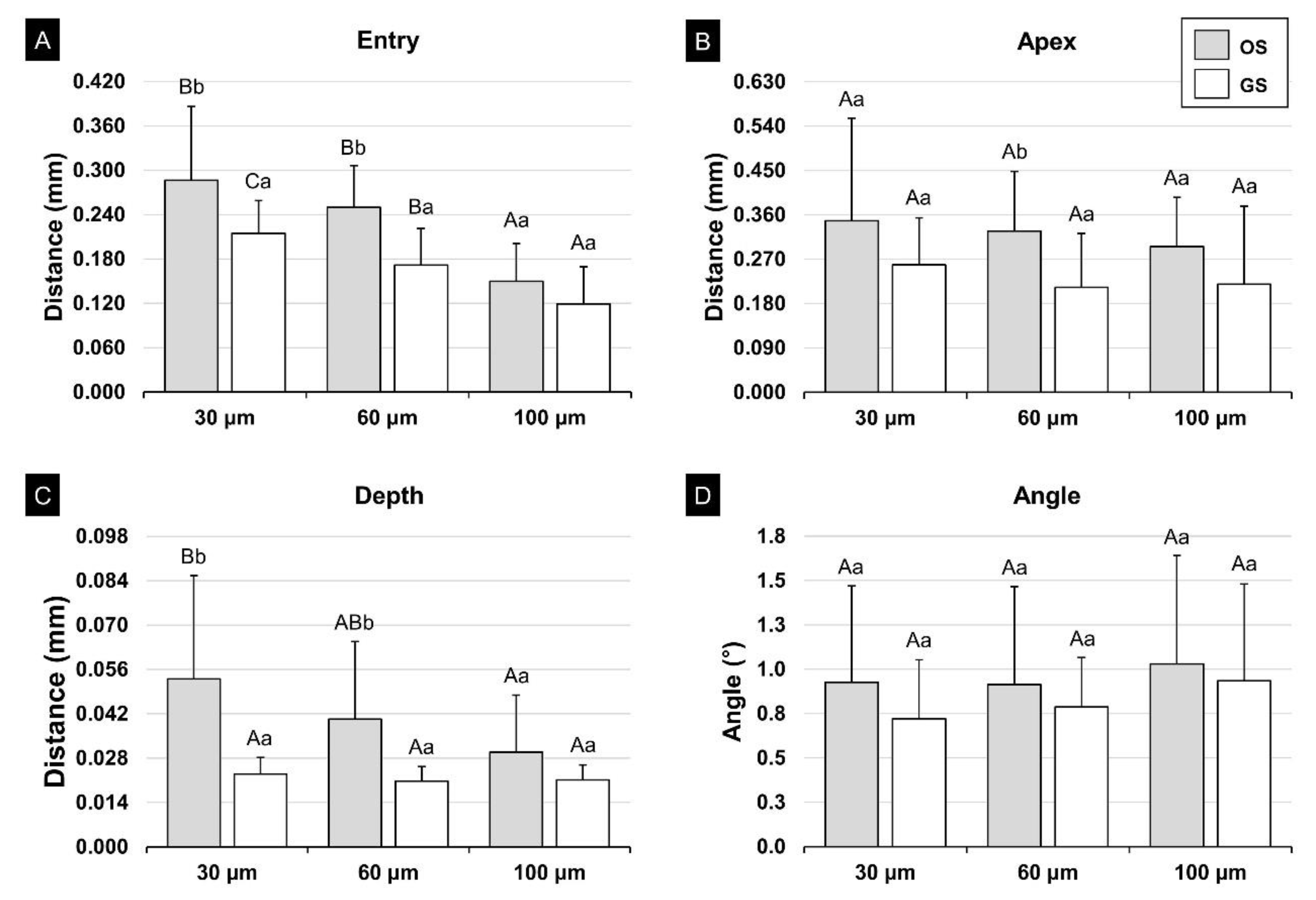
3.1. Internal Fit of the Surgical Guide
3.2. Evaluation of the Accuracy of the Implant Placement Position
4. Discussion
5. Conclusions
Author Contributions
Funding
Institutional Review Board Statement
Informed Consent Statement
Data Availability Statement
Acknowledgments
Conflicts of Interest
References
- Chen, L.; Lin, W.S.; Polido, W.D.; Eckert, G.J.; Morton, D. Accuracy, reproducibility, and dimensional stability of additively manufactured surgical templates. J. Prosthet. Dent. 2019, 122, 309–314. [Google Scholar] [CrossRef] [PubMed]
- D’Haese, J.; Ackhurst, J.; Wismeijer, D.; De Bruyn, H.; Tahmaseb, A. Current state of the art of computer-guided implant surgery. Periodontology 2017, 73, 121–133. [Google Scholar] [CrossRef] [PubMed]
- ASTM Standards. ISO/ASTM 52900: 2015 Additive Manufacturing-General Principles-Terminology; ASTM F2792-10e1; 2012; ASTM International: West Conshohocken, PA, USA, 2015. [Google Scholar]
- Salmi, M. Additive Manufacturing Processes in Medical Applications. Materials (Basel) 2021, 14, 191. [Google Scholar] [CrossRef]
- Conner, B.P.; Manogharan, G.P.; Martof, A.N.; Rodomsky, L.M.; Rodomsky, C.M.; Jordan, D.C.; Limperos, J.W. Making sense of 3-D printing: Creating a map of additive manufacturing products and services. Addit. Manuf. 2014, 1, 64–76. [Google Scholar] [CrossRef]
- Revilla-León, M.; Sadeghpour, M.; Özcan, M. An update on applications of 3D printing technologies used for processing polymers used in implant dentistry. Odontology 2020, 108, 331–338. [Google Scholar] [CrossRef]
- Stansbury, J.W.; Idacavage, M.J. 3D printing with polymers: Challenges among expanding options and opportunities. Dent. Mater. 2016, 32, 54–64. [Google Scholar] [CrossRef] [PubMed]
- Dandekeri, S.S.; Sowmya, M.K.; Bhandary, S. Stereolithographic surgical template: A review. J. Clin. Diagn. Res. 2013, 7, 2093–2095. [Google Scholar] [CrossRef]
- Nayar, S.; Bhuminathan, S.; Bhat, W.M. Rapid prototyping and stereolithography in dentistry. J. Pharm. Bioallied Sci. 2015, 7, S216. [Google Scholar] [CrossRef]
- Nickenig, H.J.; Wichmann, M.; Hamel, J.; Schlegel, K.A.; Eitner, S. Evaluation of the difference in accuracy between implant placement by virtual planning data and surgical guide templates versus the conventional free-hand method—A combined in vivo-in vitro technique using cone-beam CT (Part II). J. Craniomaxillofac. Surg. 2010, 38, 488–493. [Google Scholar] [CrossRef]
- Smitkarn, P.; Subbalekha, K.; Mattheos, N.; Pimkhaokham, A. The accuracy of single-tooth implants placed using fully digital-guided surgery and freehand implant surgery. J. Clin. Periodontol. 2019, 46, 949–957. [Google Scholar] [CrossRef] [PubMed]
- Chen, S.; Ou, Q.; Lin, X.; Wang, Y. Comparison Between a Computer-Aided Surgical Template and the Free-Hand Method: A Systematic Review and Meta-Analysis. Implant. Dent. 2019, 28, 578–589. [Google Scholar] [CrossRef]
- Zhou, W.; Liu, Z.; Song, L.; Kuo, C.L.; Shafer, D.M. Clinical Factors Affecting the Accuracy of Guided Implant Surgery-A Systematic Review and Meta-analysis. J. Evid. Based Dent. Pract. 2018, 18, 28–40. [Google Scholar] [CrossRef] [PubMed]
- Tallarico, M.; Esposito, M.; Xhanari, E.; Caneva, M.; Meloni, S.M. Computer-guided vs. freehand placement of immediately loaded dental implants: 5-year postloading results of a randomised controlled trial. Eur. J. Oral Implant. 2018, 11, 203–213. [Google Scholar]
- Mai, H.N.; Lee, D.H. Effects of supporting conditions and anchor microscrew on the stabilization of the implant guide template during the drilling process: An in vitro study. J. Prosthet. Dent. 2020, 124, 727.e1–727.e8. [Google Scholar] [CrossRef] [PubMed]
- Raico Gallardo, Y.N.; da Silva-Olivio, I.R.T.; Mukai, E.; Morimoto, S.; Sesma, N.; Cordaro, L. Accuracy comparison of guided surgery for dental implants according to the tissue of support: A systematic review and meta-analysis. Clin. Oral Implant. Res. 2017, 28, 602–612. [Google Scholar] [CrossRef] [PubMed]
- El Kholy, K.; Lazarin, R.; Janner, S.F.M.; Faerber, K.; Buser, R.; Buser, D. Influence of surgical guide support and implant site location on accuracy of static Computer-Assisted Implant Surgery. Clin. Oral Implant. Res. 2019, 30, 1067–1075. [Google Scholar] [CrossRef] [PubMed]
- Bencharit, S.; Staffen, A.; Yeung, M.; Whitley, D., 3rd; Laskin, D.M.; Deeb, G.R. In Vivo Tooth-Supported Implant Surgical Guides Fabricated With Desktop Stereolithographic Printers: Fully Guided Surgery Is More Accurate Than Partially Guided Surgery. J. Oral Maxillofac. Surg. 2018, 76, 1431–1439. [Google Scholar] [CrossRef]
- Hara, A.; Sekiguchi, H.; Yakushiji, M. Three dimensional observation of the occlusal grooves in the maxillary first and second deciduous molars with micro-CT. Pediatric Dent. J. 2008, 18, 102–115. [Google Scholar] [CrossRef] [Green Version]
- Dong, T.; Wang, X.; Xia, L.; Yuan, L.; Ye, N.; Fang, B. Accuracy of different tooth surfaces on 3D printed dental models: Orthodontic perspective. BMC Oral Health 2020, 20, 340. [Google Scholar] [CrossRef]
- Anunmana, C.; Ueawitthayasuporn, C.; Kiattavorncharoen, S.; Thanasrisuebwong, P. In Vitro Comparison of Surgical Implant Placement Accuracy Using Guides Fabricated by Three Different Additive Technologies. Appl. Sci. 2020, 10, 7791. [Google Scholar] [CrossRef]
- Cole, D.; Bencharit, S.; Carrico, C.K.; Arias, A.; Tufekci, E. Evaluation of fit for 3D-printed retainers compared with thermoform retainers. Am. J. Orthod. Dentofac. Orthop. 2019, 155, 592–599. [Google Scholar] [CrossRef] [Green Version]
- Ye, N.; Wu, T.; Dong, T.; Yuan, L.; Fang, B.; Xia, L. Precision of 3D-printed splints with different dental model offsets. Am. J. Orthod. Dentofac. Orthop. 2019, 155, 733–738. [Google Scholar] [CrossRef] [Green Version]
- Neumeister, A.; Schulz, L.; Glodecki, C. Investigations on the accuracy of 3D-printed drill guides for dental implantology. Int. J. Comput. Dent. 2017, 20, 35–51. [Google Scholar]
- Herschdorfer, L.; Negreiros, W.M.; Gallucci, G.O.; Hamilton, A. Comparison of the accuracy of implants placed with CAD-CAM surgical templates manufactured with various 3D printers: An in vitro study. J. Prosthet. Dent. 2020. [Google Scholar] [CrossRef]
- Lin, C.C.; Ishikawa, M.; Maida, T.; Cheng, H.C.; Ou, K.L.; Nezu, T.; Endo, K. Stereolithographic Surgical Guide with a Combination of Tooth and Bone Support: Accuracy of Guided Implant Surgery in Distal Extension Situation. J. Clin. Med. 2020, 9, 709. [Google Scholar] [CrossRef] [PubMed] [Green Version]
- Alharbi, N.; Osman, R.B.; Wismeijer, D. Factors Influencing the Dimensional Accuracy of 3D-Printed Full-Coverage Dental Restorations Using Stereolithography Technology. Int. J. Prosthodont. 2016, 29, 503–510. [Google Scholar] [CrossRef] [PubMed] [Green Version]
- Rebong, R.E.; Stewart, K.T.; Utreja, A.; Ghoneima, A.A. Accuracy of three-dimensional dental resin models created by fused deposition modeling, stereolithography, and Polyjet prototype technologies: A comparative study. Angle Orthod. 2018, 88, 363–369. [Google Scholar] [CrossRef] [PubMed] [Green Version]
- Akmal, J.S.; Salmi, M.; Hemming, B.; Teir, L.; Suomalainen, A.; Kortesniemi, M.; Partanen, J.; Lassila, A. Cumulative Inaccuracies in Implementation of Additive Manufacturing Through Medical Imaging, 3D Thresholding, and 3D Modeling: A Case Study for an End-Use Implant. Appl. Sci. 2020, 10, 2968. [Google Scholar] [CrossRef]
- Braian, M.; Jonsson, D.; Kevci, M.; Wennerberg, A. Geometrical accuracy of metallic objects produced with additive or subtractive manufacturing: A comparative in vitro study. Dent. Mater. 2018, 34, 978–993. [Google Scholar] [CrossRef] [PubMed]
- Lim, J.H.; Shin, S.H.; Nam, N.E.; Bayarsaikhan, E.; Shim, J.S.; Kim, J.E. Sleeve insert scan body to predict implant placement position by using implant surgical guides: A dental technique. J. Prosthet. Dent. 2021. [Google Scholar] [CrossRef]
- Hazeveld, A.; Huddleston Slater, J.J.; Ren, Y. Accuracy and reproducibility of dental replica models reconstructed by different rapid prototyping techniques. Am. J. Orthod. Dentofac. Orthop. 2014, 145, 108–115. [Google Scholar] [CrossRef]
- Gjelvold, B.; Mahmood, D.J.H.; Wennerberg, A. Accuracy of surgical guides from 2 different desktop 3D printers for computed tomography-guided surgery. J. Prosthet. Dent. 2019, 121, 498–503. [Google Scholar] [CrossRef]
- Schwarz, F.; Mihatovic, I.; Golubovich, V.; Schär, A.; Sager, M.; Becker, J. Impact of abutment microstructure and insertion depth on crestal bone changes at nonsubmerged titanium implants with platform switch. Clin. Oral Implant. Res. 2015, 26, 287–292. [Google Scholar] [CrossRef] [PubMed]
- Tallarico, M.; Martinolli, M.; Kim, Y.; Cocchi, F.; Meloni, S.M.; Alushi, A.; Xhanari, E. Accuracy of Computer-Assisted Template-Based Implant Placement Using Two Different Surgical Templates Designed with or without Metallic Sleeves: A Randomized Controlled Trial. Dent. J. (Basel) 2019, 7, 41. [Google Scholar] [CrossRef] [PubMed] [Green Version]
- Tallarico, M.; Kim, Y.J.; Cocchi, F.; Martinolli, M.; Meloni, S.M. Accuracy of newly developed sleeve-designed templates for insertion of dental implants: A prospective multicenters clinical trial. Clin. Implant. Dent. Relat. Res. 2019, 21, 108–113. [Google Scholar] [CrossRef] [PubMed] [Green Version]
- Ma, B.; Park, T.; Chun, I.; Yun, K. The accuracy of a 3D printing surgical guide determined by CBCT and model analysis. J. Adv. Prosthodont. 2018, 10. [Google Scholar] [CrossRef] [PubMed]
- Cushen, S.E.; Turkyilmaz, I. Impact of operator experience on the accuracy of implant placement with stereolithographic surgical templates: An in vitro study. J. Prosthet. Dent. 2013, 109, 248–254. [Google Scholar] [CrossRef]
- Marei, H.F.; Abdel-Hady, A.; Al-Khalifa, K.; Al-Mahalawy, H. Influence of surgeon experience on the accuracy of implant placement via a partially computer-guided surgical protocol. Int. J. Oral Maxillofac. Implant. 2019, 34, 1177–1183. [Google Scholar] [CrossRef] [PubMed]
- Spin-Neto, R.; Wenzel, A. Patient movement and motion artefacts in cone beam computed tomography of the dentomaxillofacial region: A systematic literature review. Oral Surg. Oral Med. Oral Pathol. Oral Radiol. 2016, 121, 425–433. [Google Scholar] [CrossRef]


Publisher’s Note: MDPI stays neutral with regard to jurisdictional claims in published maps and institutional affiliations. |
© 2021 by the authors. Licensee MDPI, Basel, Switzerland. This article is an open access article distributed under the terms and conditions of the Creative Commons Attribution (CC BY) license (https://creativecommons.org/licenses/by/4.0/).
Share and Cite
Lim, J.-H.; Bayarsaikhan, E.; Shin, S.-H.; Nam, N.-E.; Shim, J.-S.; Kim, J.-E. Effects of Groove Sealing of the Posterior Occlusal Surface and Offset of the Internal Surface on the Internal Fit and Accuracy of Implant Placements Using 3D-Printed Surgical Guides: An In Vitro Study. Polymers 2021, 13, 1236. https://0-doi-org.brum.beds.ac.uk/10.3390/polym13081236
Lim J-H, Bayarsaikhan E, Shin S-H, Nam N-E, Shim J-S, Kim J-E. Effects of Groove Sealing of the Posterior Occlusal Surface and Offset of the Internal Surface on the Internal Fit and Accuracy of Implant Placements Using 3D-Printed Surgical Guides: An In Vitro Study. Polymers. 2021; 13(8):1236. https://0-doi-org.brum.beds.ac.uk/10.3390/polym13081236
Chicago/Turabian StyleLim, Jung-Hwa, Enkhjargal Bayarsaikhan, Seung-Ho Shin, Na-Eun Nam, June-Sung Shim, and Jong-Eun Kim. 2021. "Effects of Groove Sealing of the Posterior Occlusal Surface and Offset of the Internal Surface on the Internal Fit and Accuracy of Implant Placements Using 3D-Printed Surgical Guides: An In Vitro Study" Polymers 13, no. 8: 1236. https://0-doi-org.brum.beds.ac.uk/10.3390/polym13081236