
Electrical and Capacitive Response of Hydrogel Solid-Like Electrolytes for Supercapacitors

 , and
, and
Abstract
:
1. Introduction
2. Methods
2.1. Materials
2.2. Synthesis
2.2.1. κ-Carrageenan (κC) Hydrogel
2.2.2. Carboxymethyl Cellulose Sodium Salt (CMC) Hydrogel
2.2.3. Poly-γ-Glutamic Acid (PGGA) Hydrogel
2.2.4. Polyesteramide (PEA) Hydrogel
2.3. Characterization
3. Results and Discussion
4. Conclusions
Author Contributions
Funding
Institutional Review Board Statement
Informed Consent Statement
Data Availability Statement
Acknowledgments
Conflicts of Interest
References
- Dubal, D.P.; Chodankar, N.R.; Kim, D.-H.; Gomez-Romero, P. Towards flexible solid-state supercapacitors for smart and wearable electronics. Chem. Soc. Rev. 2018, 47, 2065–2129. [Google Scholar] [CrossRef]
- Li, L.; Lou, Z.; Chen, D.; Jiang, K.; Han, W.; Shen, G. Recent advances in flexible/stretchable supercapacitors for wearable electronics. Small 2018, 14, 1702829. [Google Scholar] [CrossRef] [PubMed]
- Liu, Y.; He, K.; Chen, G.; Leow, W.R.; Chen, X. Nature-inspired structural materials for flexible electronic devices. Chem. Rev. 2017, 117, 12893–12941. [Google Scholar] [CrossRef] [PubMed]
- Weng, W.; Chen, P.; He, S.; Sun, X.; Peng, H. Smart electronic textiles. Angew. Chem. Int. Ed. 2016, 55, 6140–6169. [Google Scholar] [CrossRef] [PubMed]
- Zeng, W.; Shu, L.; Li, Q.; Chen, S.; Wang, F.; Tao, X.M. Fiber-based wearable electronics: A review of materials, fabrication, devices, and applications. Adv. Mater. 2014, 26, 5310–5336. [Google Scholar] [CrossRef] [PubMed]
- Evanko, B.; Boettcher, S.W.; Yoo, S.J.; Stucky, G.D. Redox-enhanced electrochemical capacitors: Status, opportunity, and best practices for performance evaluation. ACS Energy Lett. 2017, 2, 2581–2590. [Google Scholar] [CrossRef]
- Mukhopadhyay, A.; Sheldon, B.W. Deformation and stress in electrode materials for Li-ion batteries. Prog. Mater. Sci. 2014, 63, 58–116. [Google Scholar] [CrossRef]
- Xia, L.; Yu, L.; Hu, D.; Chen, G.Z. Electrolytes for electrochemical energy storage. Mater. Chem. Front. 2017, 1, 584–618. [Google Scholar] [CrossRef]
- Zhang, L.; Zhou, R.; Zhao, X.S. Graphene-based materials as supercapacitor electrodes. J. Mater. Chem. 2010, 20, 5983–5992. [Google Scholar] [CrossRef]
- Wang, X.; Gao, J.; Cheng, Z.; Chen, N.; Qu, L. A responsive battery with controlled energy release. Angew. Chem. 2016, 128, 14863–14867. [Google Scholar] [CrossRef]
- Saborio, M.G.; Lanzalaco, S.; Fabregat, G.; Puiggalí, J.; Estrany, F.; Alemán, C. Flexible electrodes for supercapacitors based on the supramolecular assembly of biohydrogel and conducting polymer. J. Phys. Chem. C 2018, 122, 1078–1090. [Google Scholar] [CrossRef] [Green Version]
- Zhao, M.Q.; Ren, C.E.; Ling, Z.; Lukatskaya, M.R.; Zhang, C.; Van Aken, K.L.; Barsoum, M.W.; Gogotsi, Y. Flexible Mxene/carbon nanotube composite paper with high volumetric capacitance. Adv. Mater. 2015, 27, 339–345. [Google Scholar] [CrossRef]
- Le, L.T.; Ervin, M.H.; Qiu, H.; Fuchs, B.E.; Lee, W.Y. Graphene supercapacitor electrodes fabricated by inkjet printing and thermal reduction of graphene oxide. Electrochem. Commun. 2011, 13, 355–358. [Google Scholar] [CrossRef]
- Lamberti, A.; Clerici, F.; Fontana, M.; Scaltrito, L. A highly stretchable supercapacitor using laser-induced graphene electrodes onto elastomeric substrate. Adv. Energy Mater. 2016, 6, 1600050. [Google Scholar] [CrossRef]
- Laelabadi, K.G.; Moradian, R.; Manouchhri, I. One-step fabrication of flexible, cost/time effective, and high energy storage reduced graphene oxide@PANI supercapacitor. ACS Appl. Energ. Mater. 2020, 3, 5301–5312. [Google Scholar] [CrossRef]
- Chen, S.; Qiu, L.; Cheng, H.-M. Carbon-based fibers for advanced electrochemical energy storage devices. Chem. Rev. 2020, 120, 2811–2878. [Google Scholar] [CrossRef] [PubMed]
- Yang, C.; Suo, Z. Hydrogel Ionotronics. Nat. Rev. Mater. 2018, 3, 125–142. [Google Scholar] [CrossRef]
- Feng, E.; Gao, W.; Li, J.; Wei, J.; Yang, Q.; Li, Z.; Ma, X.; Zhang, T.; Yang, Z. Stretchable, healable, adhesive, and redox-active multifunctional supramolecular hydrogel-based flexible supercapacitor. ACS Sustain. Chem. Eng. 2020, 8, 3311–3320. [Google Scholar] [CrossRef]
- Tong, R.P.; Chen, G.X.; Pan, D.H.; Tian, J.F.; Qi, H.S.; Li, R.A.; Lu, F.C.; He, M.H. Ultrastretchable and antifreezing double-cross-linked cellulose ionic hydrogels with high strain sensitivity under a broad range of temperature. ACS Sustain. Chem. Eng. 2019, 7, 14256–14265. [Google Scholar] [CrossRef]
- Zeng, J.; Wei, L.; Guo, X. Bio-inspired high-performance solid-state supercapacitors with the electrolyte, separator, binder and electrodes entirely from kelp. J. Mater. Chem. A 2017, 5, 25282–25292. [Google Scholar] [CrossRef]
- Sudhakar, Y.N.; Bhat, D.K.; Selvakumar, M. Ionic conductivity and dielectric studies of acid doped cellulose acetate propionate solid electrolyte for supercapacitor. Polym. Eng. Sci. 2016, 56, 196–203. [Google Scholar] [CrossRef]
- Pérez-Madrigal, M.M.; Edo, M.G.; Saborio, M.G.; Estrany, F.; Alemán, C. Pastes and hydrogels from carboxymethyl cellulose sodium salt as supporting electrolyte of solid electrochemical supercapacitors. Carbohydr. Polym. 2018, 200, 456–467. [Google Scholar] [CrossRef] [Green Version]
- Armelin, E.; Perez-Madrigal, M.M.; Alemán, C.; Díaz-Díaz, D. Current status and challenges of biohydrogels for applications as supercapacitors and secondary batteries. J. Mater. Chem. A 2016, 4, 8952–8968. [Google Scholar] [CrossRef] [Green Version]
- Nan, J.Y.; Zhang, G.T.; Zhu, T.Y.; Wang, Z.K.; Wang, L.J.; Wang, H.S.; Chu, F.X.; Wang, C.P.; Tang, C.B. A highly elastic and fatigue-resistant natural protein-reinforced hydrogel electrolyte for reversible-compressible quasi-solid-state supercapacitors. Adv. Sci. 2020, 7, 2000587. [Google Scholar] [CrossRef] [PubMed]
- Xun, Z.Y.; Ni, S.P.; Gao, Z.H.; Zhang, Y.H.; Gu, J.Y.; Huo, P.F. Construction of polymer electrolyte based on soybean protein isolate and hydroxyethyl cellulose for a flexible solid-state supercapacitor. Polymers 2019, 11, 1895. [Google Scholar] [CrossRef] [Green Version]
- Huo, P.F.; Ni, S.P.; Hou, P.; Xun, Z.Y.; Liu, Y.; Gu, J.Y. A crosslinked soybean protein isolate gel polymer electrolyte based on neutral aqueous electrolyte for a high-energy-density supercapacitor. Polymers 2019, 11, 863. [Google Scholar] [CrossRef] [Green Version]
- Pérez-Madrigal, M.M.; Edo, M.G.; Díaz, A.; Puiggalí, J.; Alemán, C. Poly-γ-glutamic acid hydrogels as electrolyte for poly(3,4-ethylenedioxythiophene)-based supercapacitors. J. Phys. Chem. C 2017, 121, 3182–3193. [Google Scholar] [CrossRef] [Green Version]
- Ruano, G.; Díaz, A.; Tononi, J.; Torras, J.; Puiggalí, J.; Alemán, C. Biohydrogel from unsaturated polyesteramide: Synthesis, properties and utilization as electrolytic medium for electrochemical supercapacitors. Polym. Test. 2020, 82, 106300. [Google Scholar] [CrossRef]
- Ruano, G.; Tononi, J.; Curcó, D.; Puiggali, J.; Torras, J.; Alemán, C. Doped photo-crosslinked polyesteramide hydrogels as solid electrolytes for supercapacitors. Soft Matter 2020, 16, 8033–8046. [Google Scholar] [CrossRef] [PubMed]
- Choudhury, N.A.; Sampathb, S.; Shukla, A.K. Hydrogel-polymer electrolytes for electrochemical capacitors: An overview. Energy Environ. Sci. 2009, 2, 55–67. [Google Scholar] [CrossRef] [Green Version]
- Inoue, H.; Inaba, Y.; Okuda, S.; Higuchi, E.; Nohara, S. Inorganic hydrogel electrolyte with liquidlike ionic conductivity. Electrochem. Solid-State Lett. 2009, 12, A58. [Google Scholar] [CrossRef]
- Yuan, A.; Zhao, J. Composite alkaline polymer electrolytes and its application to nickel–metal hydride batteries. Electrochim. Acta 2006, 51, 2454–2462. [Google Scholar] [CrossRef]
- Nohara, S.; Wada, H.; Furukawa, N.; Inoue, H.; Morita, M.; Iwakura, C. Electrochemical characterization of new electric double layer capacitor with polymer hydrogel electrolyte. Electrochim. Acta 2003, 48, 749–753. [Google Scholar] [CrossRef]
- Rochas, C.; Rinaudo, M. Mechanism of gel formation in κ-carrageenan. Biopolymers 1984, 23, 735–745. [Google Scholar] [CrossRef]
- Jiang, W.; Gao, J.; Wei, Z.; Zhou, J.; Mei, Y. Facile fabrication of self-healing carboxymethyl cellulose hydrogels. Eur. Polym. J. 2015, 72, 514–522. [Google Scholar]
- Matsusaki, M.; Yoshida, H.; Akashi, M. The construction of 3D-engineered tissues composed of cells and extracellular matrices by hydrogel template approach. Biomaterials 2007, 28, 2729–2737. [Google Scholar] [CrossRef] [PubMed]
- Guo, K.; Chu, C.C.; Chkhaidze, E.; Katsarava, R. Synthesis and characterization of novel biodegradable unsaturated poly(ester amide)s. J. Polym. Sci. Part A Polym. Chem. 2005, 43, 1463–1477. [Google Scholar] [CrossRef]
- Yang, I.; Kim, S.-G.; Kwon, S.H.; Kim, M.-S.; Jung, J.C. Relationships between pore size and charge transfer resistance of carbon aerogels for organic electric double-layer capacitor electrodes. Electrochim. Acta 2017, 223, 21–30. [Google Scholar] [CrossRef]
- Wang, X.; Xu, J.; Razal, J.M.; Yuan, N.; Zhou, X.; Wang, X.; Ding, J.; Qin, S.; Geb, S.; Gogotsi, Y. Unimpeded migration of ions in carbon electrodes with bimodal pores at an ultralow temperature of −100 °C. J. Mater. Chem. A 2019, 7, 16339–16346. [Google Scholar] [CrossRef]
- Nguyen, T.-T.; Demortière, A.; Fleutot, B.; Delobel, B.; Delacourt, C.; Cooper, S.J. The electrode tortuosity factor: Why the conventional tortuosity factor is not well suited for quantifying transport in porous Li-ion battery electrodes and what to use instead. NPJ Comput. Mater. 2020, 6, 123. [Google Scholar] [CrossRef]
- Sun, K.; Dong, M.; Feng, E.; Peng, H.; Ma, G.; Zhao, G.; Lei, Z. High performance solid state supercapacitor based on a 2-mercaptopyridine redox-mediated gel polymer. RSC Adv. 2015, 5, 22419–22425. [Google Scholar] [CrossRef]
- Mallakpour, S.; Abdolmaleki, A.; Borandeh, S.; Khalesi, Z. Surface functionalization of GO, preparation and characterization of PVA/TRIS-GO nanocomposites. Polymer 2015, 81, 140–150. [Google Scholar] [CrossRef]
- Ma, G.; Dong, M.; Sun, K.; Feng, E.; Peng, H.; Lei, Z. A redox mediator doped gel polymer as an electrolyte and separator for a high performance solid state supercapacitor. J. Mater. Chem. A 2015, 3, 4035–4041. [Google Scholar] [CrossRef]
- Guo, L.; Ma, W.-B.; Wang, Y.; Sing, X.-Z.; Ma, J.; Han, X.-D.; Tao, X.-Y.; Guo, L.-T.; Fan, H.-L.; Liu, Z.-S.; et al. A chemically crosslinked hydrogel electrolyte based all-in-one flexible supercapacitor with superior performance. J. Alloys Compd. 2020, 843, 155895. [Google Scholar] [CrossRef]
- Sun, K.; Feng, E.; Zhao, G.; Peng, H.; Wei, G.; Ly, Y.; Ma, G. A Single robust hydrogel film based integrated flexible supercapacitor. ACS Sustain. Chem. Eng. 2019, 7, 165–173. [Google Scholar] [CrossRef]
- Widodo, C.S.; Sela, H.; Santos, D.R. The effect of NaCl concentration on the ionic NaCl solutions electrical impedancevalue using electrochemical impedancespectroscopy methods. AIP Conf. Proc. 2018, 2021, 050003. [Google Scholar] [CrossRef]
- Vyas, R.N.; Wang, B. Electrochemical analysis of conducting polymer thin films. Int. J. Mol. Sci. 2010, 11, 1956–1972. [Google Scholar] [CrossRef] [PubMed] [Green Version]
- Jorcin, J.-B.; Orazen, M.E.; Pébère, N.; Tribollet, B. CPE analysis by local electrochemical impedance spectroscopy. Electrochim. Acta 2006, 51, 14731479. [Google Scholar] [CrossRef]
- Zubair, N.A.; Rahman, N.A.; Lim, H.N.; Sulaiman, Y. Production of conductive PEDOT-coatedPVA-GO composite nanofibers. Nanoscale Res. Lett. 2017, 12, 113. [Google Scholar] [CrossRef] [PubMed] [Green Version]
- Dziewonski, P.M.; Grzeszczuk, M. Towards TiO2-conducting polymer hybrid materials for lithium ion batteries. Electrochim. Acta 2010, 55, 3336–3347. [Google Scholar] [CrossRef]


| Hydrogel | D (µm) | SR (%) | RS (Ω) | RP (Ω) |
|---|---|---|---|---|
| κC | 26 ± 9 | 1070 ± 122 | 8.18 | 2.89 |
| CMC | 52 ± 14 | 2356 ± 241 | 6.27 | 5.57 |
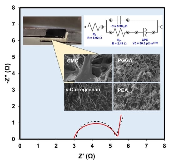
| PGGA | 19 ± 8 | 483 ± 39 | 5.92 | 2.49 |
| PEA | 17 ± 7 | 1416 ± 297 | 3.11 | 2.17 |
Publisher’s Note: MDPI stays neutral with regard to jurisdictional claims in published maps and institutional affiliations. |
© 2021 by the authors. Licensee MDPI, Basel, Switzerland. This article is an open access article distributed under the terms and conditions of the Creative Commons Attribution (CC BY) license (https://creativecommons.org/licenses/by/4.0/).
Share and Cite
Ruano, G.; Iribarren, J.I.; Pérez-Madrigal, M.M.; Torras, J.; Alemán, C. Electrical and Capacitive Response of Hydrogel Solid-Like Electrolytes for Supercapacitors. Polymers 2021, 13, 1337. https://0-doi-org.brum.beds.ac.uk/10.3390/polym13081337
Ruano G, Iribarren JI, Pérez-Madrigal MM, Torras J, Alemán C. Electrical and Capacitive Response of Hydrogel Solid-Like Electrolytes for Supercapacitors. Polymers. 2021; 13(8):1337. https://0-doi-org.brum.beds.ac.uk/10.3390/polym13081337
Chicago/Turabian StyleRuano, Guillem, José I. Iribarren, Maria M. Pérez-Madrigal, Juan Torras, and Carlos Alemán. 2021. "Electrical and Capacitive Response of Hydrogel Solid-Like Electrolytes for Supercapacitors" Polymers 13, no. 8: 1337. https://0-doi-org.brum.beds.ac.uk/10.3390/polym13081337