
Influence of the Cross-Sectional Shape and Corner Radius on the Compressive Behaviour of Concrete Columns Confined by FRP and Stirrups


Abstract
:1. Introduction
2. Test Investigation
2.1. Parameters and Materials
2.2. Construction of the Specimens
2.3. Test Setup and Loading
3. Test Results
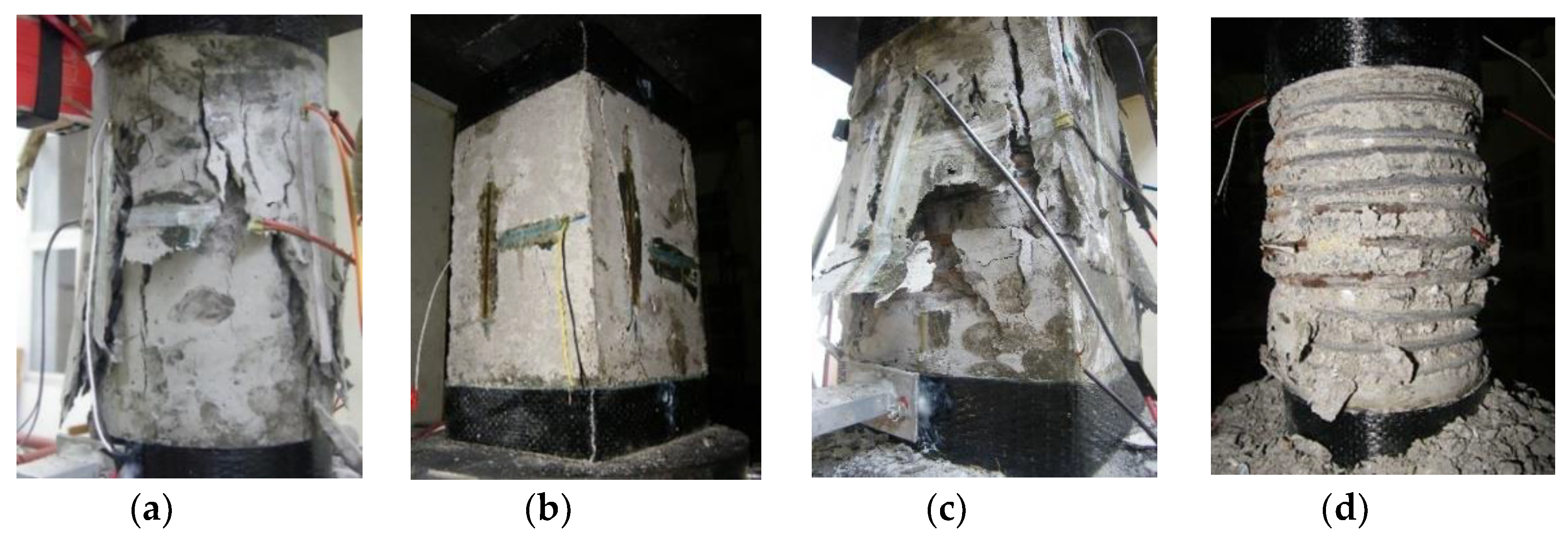
3.1. Failure Modes
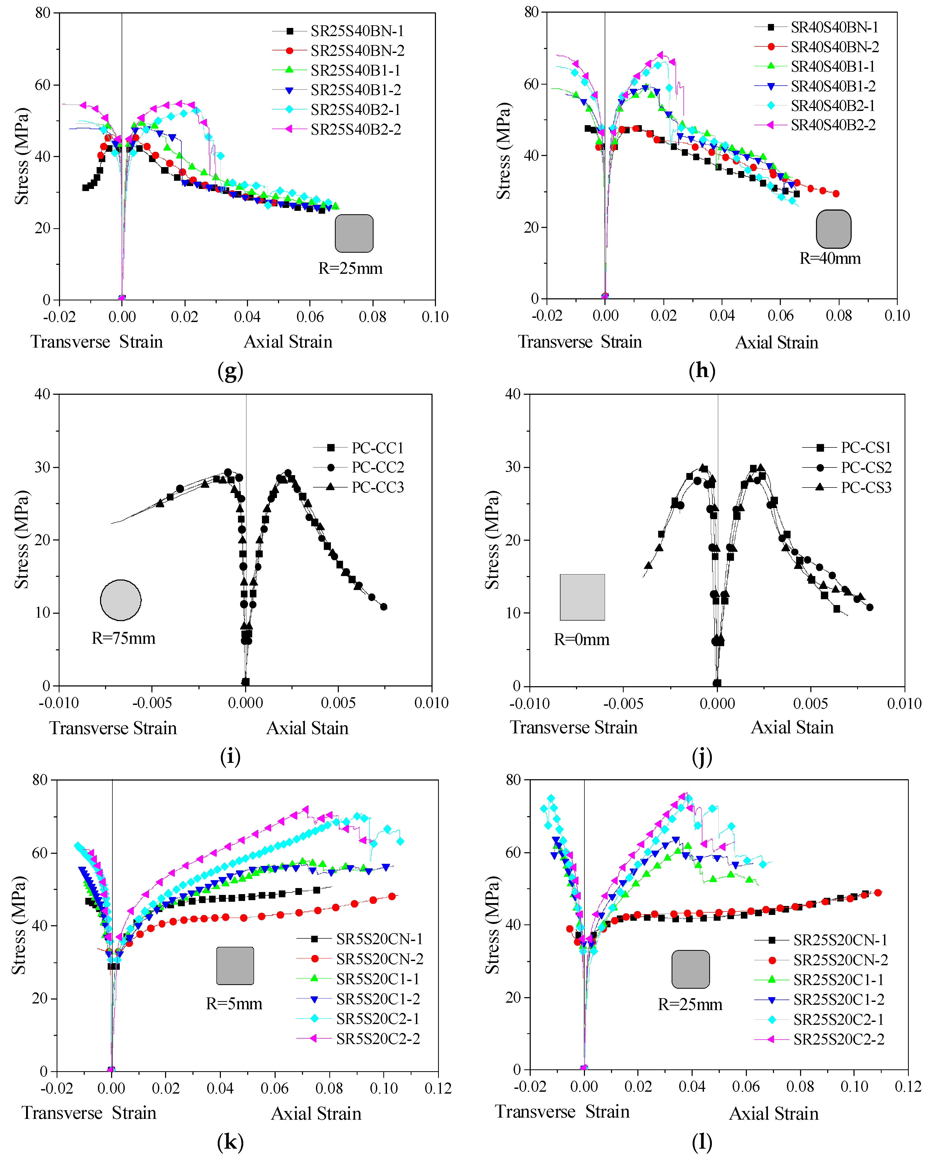
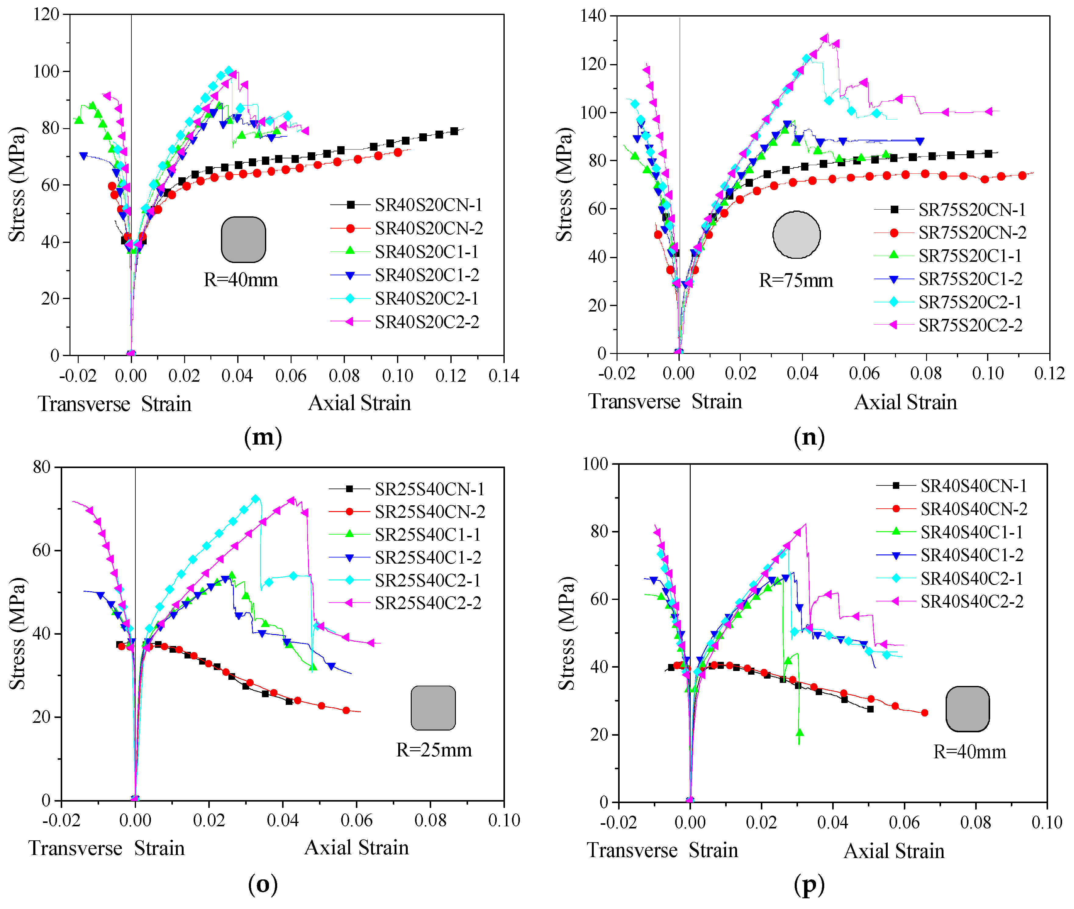
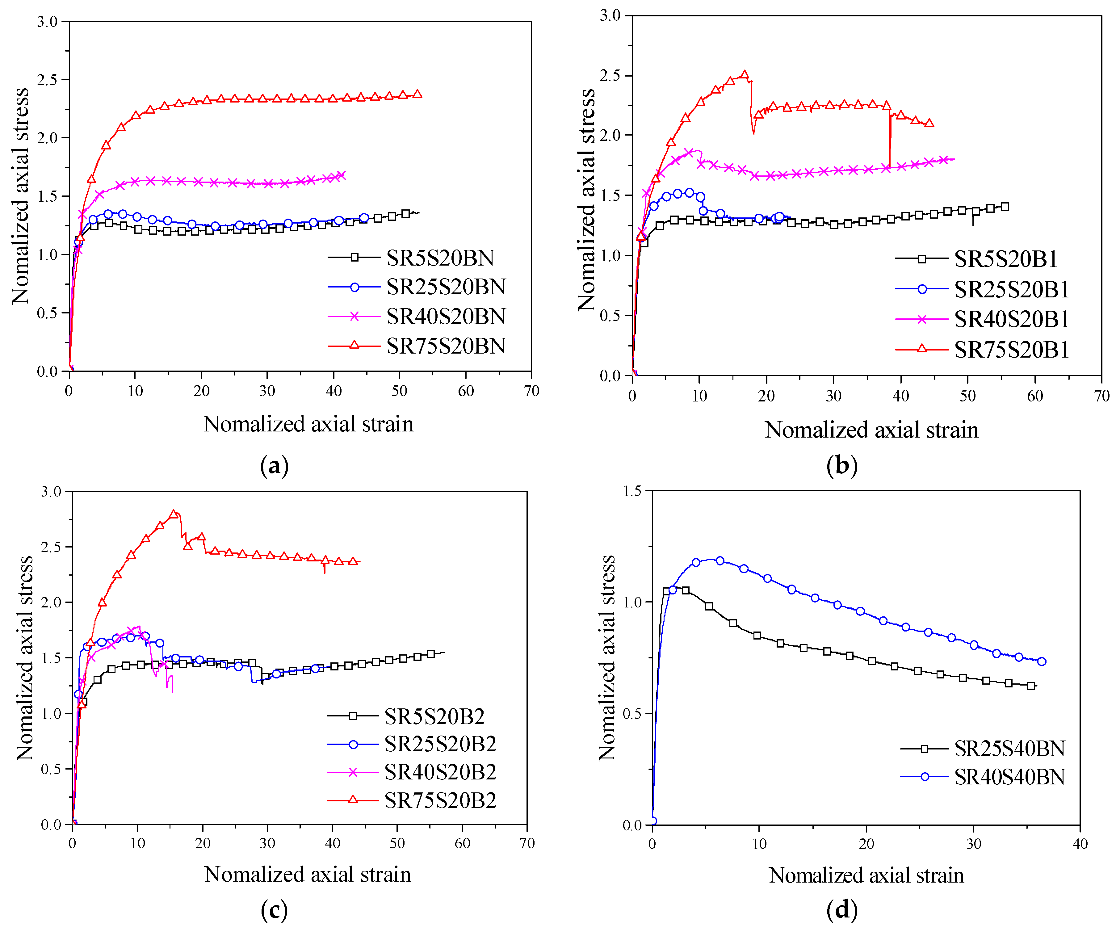
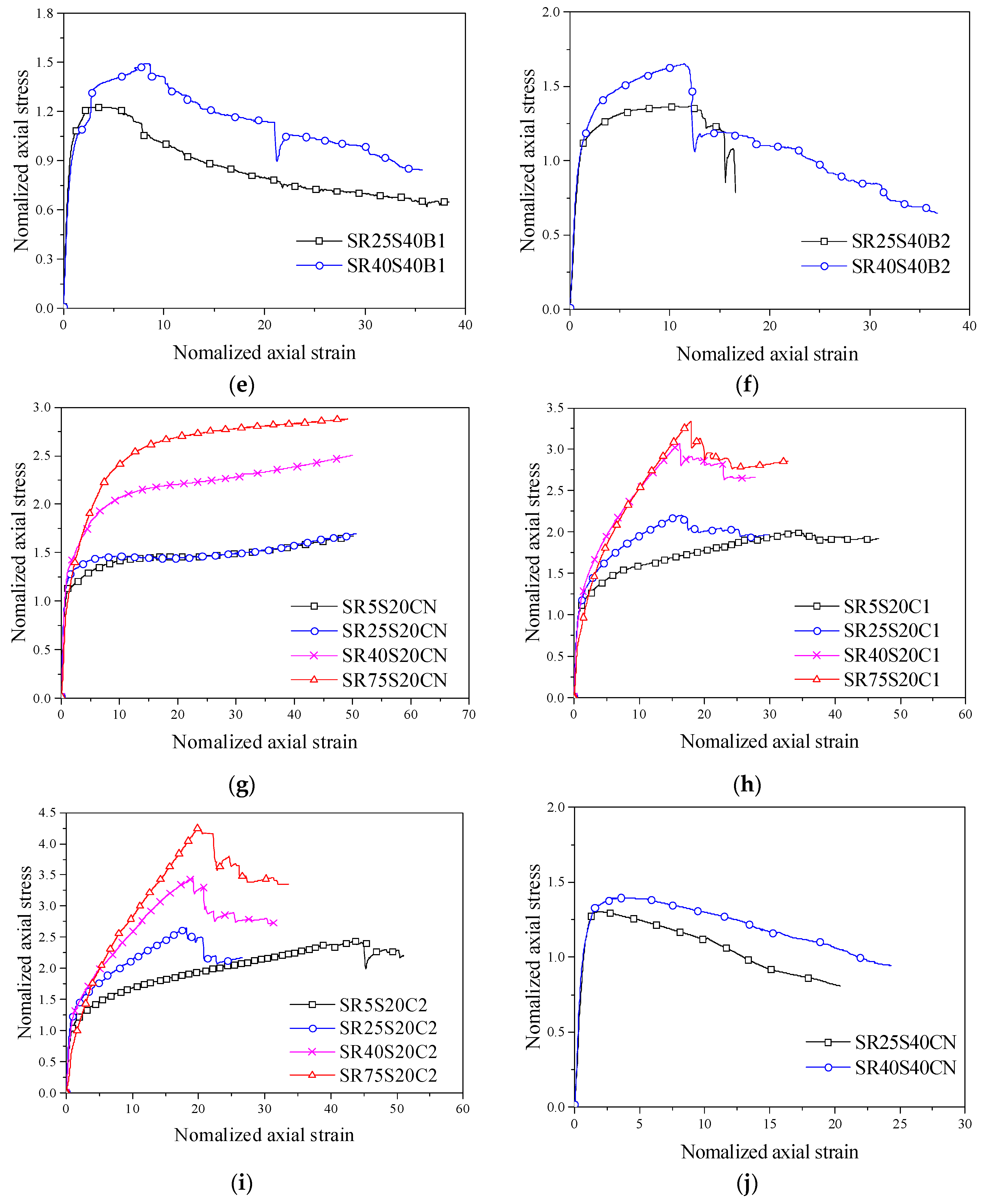
3.2. Stress–Strain Response
3.3. Influence of Parameters on the Compressive Behaviour of Confined Concrete
4. Existing Models
4.1. Effective Confinement Pressure
4.2. Confinement Models
5. Proposed Analytical Model
5.1. Test Database
5.2. Stress–Strain Relationship Modelling
5.3. Ultimate Stress fcu and Ultimate Strain εcu
5.4. Peak Stress fcc and Peak Strain εcc
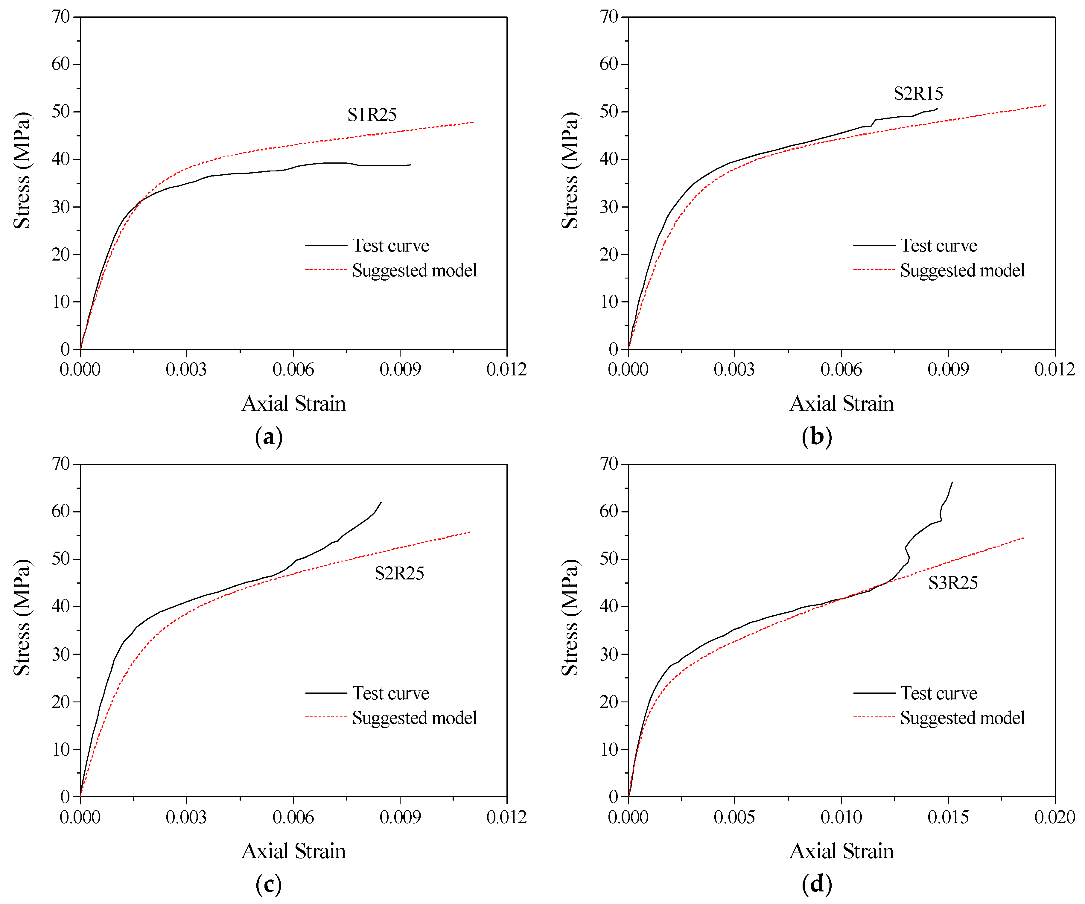
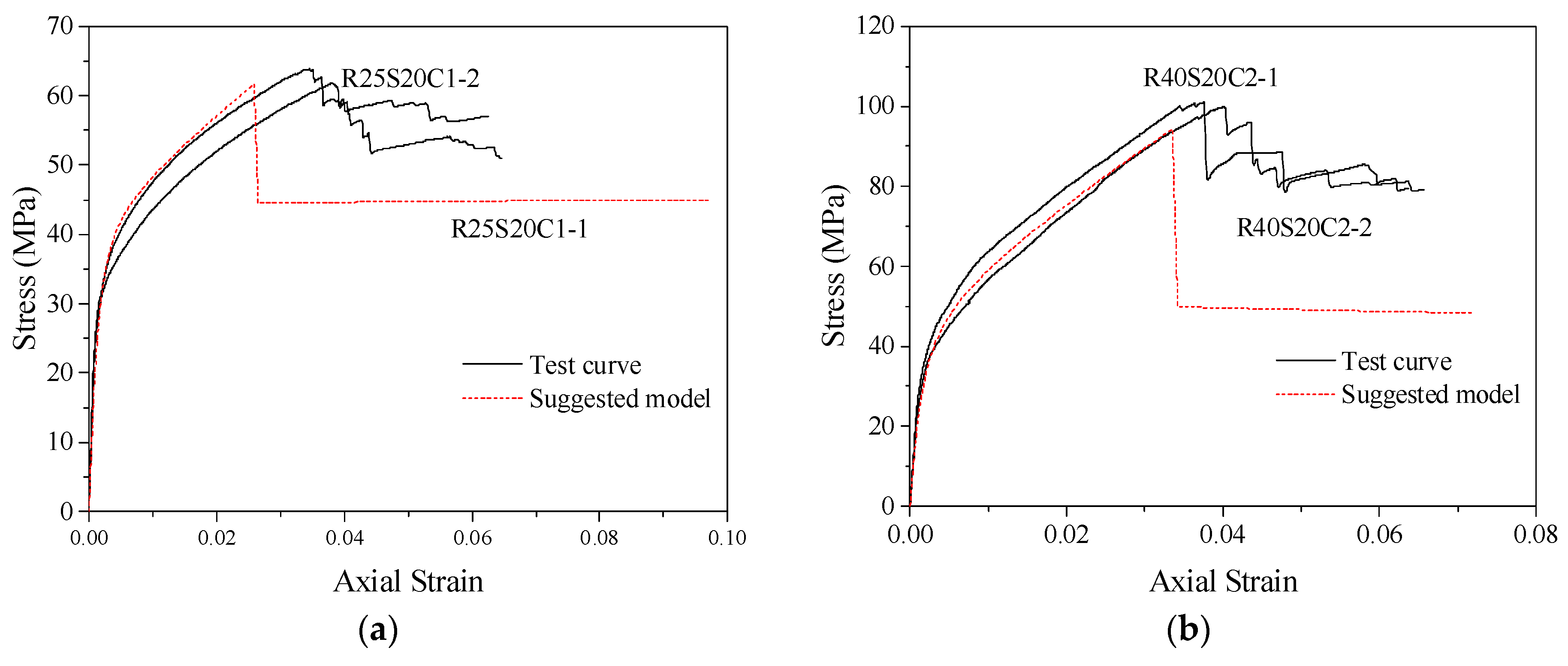
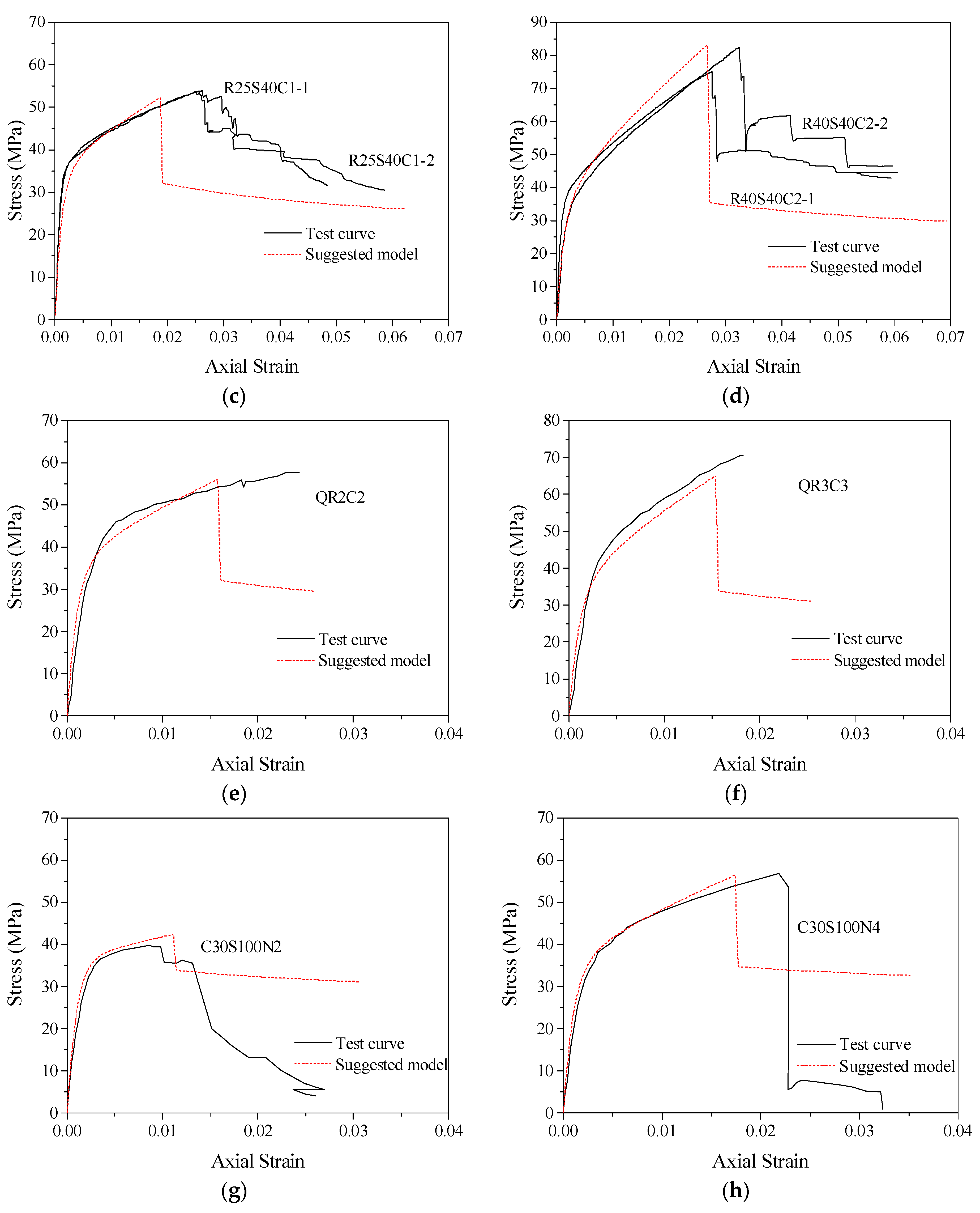
5.5. Model Performance
6. Conclusions
- (1)
- The cross-sectional shape directly affects the confinement efficiency of confined concrete columns. Compared with the circular section, the lateral confinement forces of confined rectangular section concrete columns are unevenly distributed around the section. The confinement efficiency of rectangular concrete columns is worse than that of circular concrete columns.
- (2)
- For the FRP–stirrup composite-confined concrete columns with a small corner radius, FRP tensile fractures occur at the corners of the columns. For the specimens with a large corner radius, the FRP exhibited tensile failure or delamination; tensile failure occurred not only at the corners but also at the sides of the concrete columns.
- (3)
- The larger the corner radius is, the closer the section approaches the circular section, the more uniform the lateral expansion deformation of concrete is and the more effective the lateral restraint provided by the FRP.
- (4)
- The larger the corner radius is, the greater the slope and stiffness of the specimen in the strengthening stage; the more backwards the peak points and the ultimate points on the curves are; the stronger the ultimate bearing capacity and deformation capacity values of the specimens, especially for the specimens with a corner radius of 75 mm (a circular section).
- (5)
- By introducing the effective confinement coefficient and cross-sectional shape coefficient of FRP and further considering the effect of a smaller corner radius on the confinement of core concrete columns, the peak points, ultimate points and stress–strain curve models are applicable to FRP, stirrup and FRP–stirrup-confined concrete columns with different cross-sectional shapes (circular, square and square with rounded corners)proposed, which was verified by a large number of confined concrete columns.
Author Contributions
Funding
Institutional Review Board Statement
Informed Consent Statement
Data Availability Statement
Conflicts of Interest
References
- Liu, Y.; Zeng, L.; Xiang, S.; Mo, J.; Zhang, J.; Chen, J.; Cheng, G. Compressive performance evaluation of concrete confined by stirrups at elevated temperature using DIC technology. Constr. Build. Mater. 2020, 260, 119883. [Google Scholar] [CrossRef]
- Xue, J.; Zhao, X.; Ke, X.; Zhang, X.; Zhang, F.; Zhang, P. Experimental and numerical investigation of high-strength concrete encased steel columns with rectangular-spiral stirrups. J. Build. Eng. 2020, 32, 101518. [Google Scholar] [CrossRef]
- Zeng, J.-J.; Gao, W.-Y.; Duan, Z.-J.; Bai, Y.-L.; Guo, Y.-C.; Ouyang, L.-J. Axial compressive behavior of polyethylene terephthalate/carbon FRP-confined seawater sea-sand concrete in circular columns. Constr. Build. Mater. 2020, 234, 117383. [Google Scholar] [CrossRef]
- Moran, D.A.; Pantelides, C.P.; Reaveley, L.D. Mohr-coulomb model for rectangular and square FRP-confined concrete. Compos. Struct. 2019, 209, 889–904. [Google Scholar] [CrossRef]
- Ahmed, A.A.; Hassan, M.; Masmoudi, R. Effect of concrete strength and tube thickness on the flexural behavior of prestressed rectangular concrete-filled FRP tubes beams. Eng. Struct. 2020, 205, 110112. [Google Scholar] [CrossRef]
- Jiang, J.; Li, P.; Nisticò, N. Local and global prediction on stress-strain behavior of FRP-confined square concrete sections. Compos. Struct. 2019, 226, 111205. [Google Scholar] [CrossRef]
- Ozbakkaloglu, T. Behavior of square and rectangular ultra high-strength concrete-filled FRP tubes under axial compression. Compos. Part B Eng. 2013, 54, 97–111. [Google Scholar] [CrossRef]
- Yang, J.; Wang, J.; Wang, Z. Rectangular high-strength concrete columns confined with carbon fiber-reinforced polymer (CFRP) under eccentric compression loading. Constr. Build. Mater. 2018, 193, 604–622. [Google Scholar] [CrossRef]
- Zeng, J.-J.; Liao, J.; Ye, Y.-Y.; Guo, Y.-C.; Zheng, Y.; Tan, L.-H. Behavior of FRP spiral strip-confined concrete under cyclic axial compression. Constr. Build. Mater. 2021, 295, 123544. [Google Scholar] [CrossRef]
- Ferdous, W.; Manalo, A.; AlAjarmeh, O.; Zhuge, Y.; Mohammed, A.; Bai, Y.; Aravinthan, T.; Schubel, P. Bending and Shear Behaviour of Waste Rubber Concrete-Filled FRP Tubes with External Flanges. Polymers 2021, 13, 2500. [Google Scholar] [CrossRef]
- Alajarmeh, O.; Manalo, A.; Benmokrane, B.; Ferdous, W.; Mohammed, A.; Abousnina, R.; Elchalakani, M.; Edoo, A. Behavior of circular concrete columns reinforced with hollow composite sections and GFRP bars. Mar. Struct. 2020, 72, 102785. [Google Scholar] [CrossRef]
- Abd El Fattah, A. New axial Stress-Strain model of square concrete columns confined with lateral steel and FRP. Compos. Struct. 2018, 202, 731–751. [Google Scholar] [CrossRef]
- Guo, Y.; Xiao, S.; Shi, S.; Zeng, J.; Wang, W.; Zhao, H. Axial compressive behavior of concrete-filled FRP-steel wire reinforced ther-moplastics pipe hybrid columns. Compos. Struct. 2020, 244, 112237. [Google Scholar] [CrossRef]
- Ren, F.; Liang, Y.; Ho, J.; Lai, M. Behaviour of FRP tube-concrete-encased steel composite columns. Compos. Struct. 2020, 241, 112139. [Google Scholar] [CrossRef]
- Wei, Y.; Zhang, X.; Wu, G.; Zhou, Y. Behaviour of concrete confined by both steel spirals and fiber-reinforced polymer under axial load. Compos. Struct. 2018, 192, 577–591. [Google Scholar] [CrossRef]
- Wei, Y.; Zhang, Y.; Chai, J.; Wu, G.; Dong, Z. Experimental investigation of rectangular concrete-filled fiber reinforced polymer (FRP)-steel composite tube columns for various corner radii. Compos. Struct. 2020, 244, 112311. [Google Scholar] [CrossRef]
- Liu, J.; Xu, T.; Guo, Y.; Wang, X.; Chen, Y.F. Behavior of circular CFRP-steel composite tubed high-strength concrete columns under axial compression. Compos. Struct. 2019, 211, 596–609. [Google Scholar] [CrossRef]
- Wang, Y.; Cai, G.; Si Larbi, A.; Waldmann, D.; Tsavdaridis, D.K.; Ran, J. Monotonic axial compressive behaviour and con-finement mechanism of square CFRP-steel tube confined concrete. Eng. Struct. 2020, 217, 110802. [Google Scholar] [CrossRef]
- Zhang, Y.; Wei, Y.; Miao, K.; Li, B. A novel seawater and sea sand concrete-filled FRP-carbon steel composite tube column: Cyclic axial compression behaviour and modelling. Eng. Struct. 2022, 252, 113531. [Google Scholar] [CrossRef]
- Huang, L.; Zhang, S.; Yu, T.; Wang, Z. Compressive behaviour of large rupture strain FRP-confined concrete-encased steel columns. Constr. Build. Mater. 2018, 183, 513–522. [Google Scholar] [CrossRef]
- Güneyisi, E.M.; Nour, A.I. Axial compression capacity of circular CFST columns transversely strengthened by FRP. Eng. Struct. 2019, 191, 417–431. [Google Scholar] [CrossRef]
- Laterza, M.; D’Amato, M.; Braga, F.; Gigliotti, R. Extension to rectangular section of an analytical model for concrete confined by steel stirrups and/or FRP jackets. Compos. Struct. 2017, 176, 910–922. [Google Scholar] [CrossRef]
- Wei, Y.; Zhu, C.; Miao, K.; Chai, J.; Zheng, K. Compressive behavior of rectangular concrete-filled fiber-reinforced polymer and steel composite tube columns with stress-release grooves. Compos. Struct. 2022, 281, 114984. [Google Scholar] [CrossRef]
- Liao, J.; Yang, K.Y.; Zeng, J.-J.; Quach, W.-M.; Ye, Y.-Y.; Zhang, L. Compressive behavior of FRP-confined ultra-high performance concrete (UHPC) in circular columns. Eng. Struct. 2021, 249, 113246. [Google Scholar] [CrossRef]
- Li, Y.; Teng, J.; Zhao, X.; Raman, R.S. Theoretical model for seawater and sea sand concrete-filled circular FRP tubular stub columns under axial compression. Eng. Struct. 2018, 160, 71–84. [Google Scholar] [CrossRef]
- Li, Y.L.; Zhao, X.L.; Singh Raman, R.K. Mechanical properties of seawater and sea sand concrete-filled FRP tubes in artificial sea-water. Constr Build Mater. 2018, 191, 977–993. [Google Scholar] [CrossRef]
- Ozbakkaloglu, T.; Akin, E. Behavior of FRP-Confined Normal- and High-Strength Concrete under Cyclic Axial Compression. J. Compos. Constr. 2012, 16, 451–463. [Google Scholar] [CrossRef] [Green Version]
- Guo, Y.-C.; Gao, W.-Y.; Zeng, J.-J.; Duan, Z.-J.; Ni, X.-Y.; Peng, K.-D. Compressive behavior of FRP ring-confined concrete in circular columns: Effects of specimen size and a new design-oriented stress-strain model. Constr. Build. Mater. 2019, 201, 350–368. [Google Scholar] [CrossRef]
- Wang, Y.; Chen, G.; Wan, B.; Han, B.; Ran, J. Axial compressive behavior and confinement mechanism of circular FRP-steel tubed concrete stub columns. Compos. Struct. 2021, 256, 113082. [Google Scholar] [CrossRef]
- Wang, G.; Wei, Y.; Miao, K.; Zheng, K.; Dong, F. Axial compressive behavior of seawater sea-sand coral aggregate concrete-filled circular FRP-steel composite tube columns. Constr. Build. Mater. 2022, 315, 125737. [Google Scholar] [CrossRef]
- Wei, Y.; Bai, J.; Zhang, Y.; Miao, K.; Zheng, K. Compressive performance of high-strength seawater and sea sand concrete-filled circular FRP-steel composite tube columns. Eng. Struct. 2021, 240, 112357. [Google Scholar] [CrossRef]
- Liu, J.-P.; Xu, T.-X.; Wang, Y.-H.; Guo, Y. Axial behaviour of circular steel tubed concrete stub columns confined by CFRP materials. Constr. Build. Mater. 2018, 168, 221–231. [Google Scholar] [CrossRef]
- Sun, J.; Wei, Y.; Wang, Z.; Li, X. A new composite column of FRP-steel-FRP clad tube filled with seawater sea-sand coral aggregate concrete: Concept and compressive behavior. Constr. Build. Mater. 2021, 301, 124096. [Google Scholar] [CrossRef]
- Zhou, J.-K.; Lin, W.-K.; Guo, S.-X.; Zeng, J.-J.; Bai, Y.-L. Behavior of FRP-confined FRP spiral reinforced concrete square columns (FCFRCs) under axial compression. J. Build. Eng. 2022, 45, 103452. [Google Scholar] [CrossRef]
- Wang, W.; Sheikh, M.N.; Hadi, M.N.; Gao, D.; Chen, G. Behaviour of concrete-encased concrete-filled FRP tube (CCFT) columns under axial compression. Eng. Struct. 2017, 147, 256–268. [Google Scholar] [CrossRef] [Green Version]
- Ceccato, C.; Teng, J.; Cusatis, G. Numerical prediction of the ultimate condition of circular concrete columns confined with a fiber reinforced polymer jacket. Compos. Struct. 2020, 241, 112103. [Google Scholar] [CrossRef]
- Shen, Q.; Wang, J.; Wang, J.; Ding, Z. Axial compressive performance of circular CFST columns partially wrapped by carbon FRP. J. Constr. Steel Res. 2019, 155, 90–106. [Google Scholar] [CrossRef]
- Abdelrahman, K.; El-Hacha, R. Analytical prediction model for circular SMA-confined reinforced concrete columns. Eng. Struct. 2020, 213, 110547. [Google Scholar] [CrossRef]
- Shirmohammadi, F.; Esmaeily, A.; Kiaeipour, Z. Stress–strain model for circular concrete columns confined by FRP and conven-tional lateral steel. Eng. Struct. 2015, 84, 395–405. [Google Scholar] [CrossRef]
- Ayough, P.; Ibrahim, Z.; Sulong, N.R.; Hsiao, P.-C. The effects of cross-sectional shapes on the axial performance of concrete-filled steel tube columns. J. Constr. Steel Res. 2020, 176, 106424. [Google Scholar] [CrossRef]
- Ding, F.-X.; Liu, J.; Liu, X.; Yu, Z.-W.; Li, D.-W. Mechanical behavior of circular and square concrete filled steel tube stub columns under local compression. Thin-Walled Struct. 2015, 94, 155–166. [Google Scholar] [CrossRef] [Green Version]
- Zhu, J.-Y.; Chan, T.-M. Experimental investigation on steel-tube-confined-concrete stub column with different cross-section shapes under uniaxial-compression. J. Constr. Steel Res. 2019, 162, 105729. [Google Scholar] [CrossRef]
- Yaqub, M.; Bailey, C. Cross sectional shape effects on the performance of post-heated reinforced concrete columns wrapped with FRP composites. Compos. Struct. 2011, 93, 1103–1117. [Google Scholar] [CrossRef]
- Zheng, J.; Ozbakkaloglu, T. Sustainable FRP–recycled aggregate concrete–steel composite columns: Behavior of circular and square columns under axial compression. Thin-Walled Struct. 2017, 120, 60–69. [Google Scholar] [CrossRef]
- Gao, P.; Sun, D.; Zhao, Y.; Hong, L.; Wang, Z.; Chen, T. Effect of the corner radius on the axial compressive performance of large steel-reinforced concrete columns confined by carbon fibre-reinforced polymer. Eng. Struct. 2021, 239, 112303. [Google Scholar] [CrossRef]
- Li, P.; Yang, T.; Zeng, Q.; Xing, F.; Zhou, Y. Axial stress–strain behavior of carbon FRP-confined seawater sea-sand recycled ag-gregate concrete square columns with different corner radii. Compos Struct. 2021, 262, 113589. [Google Scholar] [CrossRef]
- Wang, L.-M.; Wu, Y.-F. Effect of corner radius on the performance of CFRP-confined square concrete columns: Test. Eng. Struct. 2008, 30, 493–505. [Google Scholar] [CrossRef]
- Ceccato, C.; Salviato, M.; Pellegrino, C.; Cusatis, G. Simulation of concrete failure and fiber reinforced polymer fracture in confined columns with different cross sectional shape. Int. J. Solids Struct. 2017, 108, 216–229. [Google Scholar] [CrossRef]
- Huang, L.; Liang, J.; Gao, C.; Yan, L. Flax FRP tube and steel spiral dual-confined recycled aggregate concrete: Experimental and analytical studies. Constr. Build. Mater. 2021, 300, 124023. [Google Scholar] [CrossRef]
- Chang, W.; Hao, M.; Zheng, W. Compressive behavior of UHPC confined by both spiral stirrups and carbon fiber-reinforced polymer (CFRP). Constr. Build. Mater. 2019, 230, 117007. [Google Scholar] [CrossRef]
- Standard for Test Methods of Mechanical Properties on Ordinary Concrete; Standard Press of China: Beijing, China, 2016.
- Metallic Materials Tensile Testing at Ambient Temperature; Standard Press of China: Beijing, China, 2010.
- Test Method for Tensile Properties of Orientation Fiber Reinforced Polymer Matrix Composite Materials; Standard Press of China: Beijing, China, 2014.
- Mander, J.B.; Priestley, M.J.N.; Park, R. Theoretical stress-strain model for confined concrete. J. Struct. Eng. 1988, 114, 1804–1826. [Google Scholar] [CrossRef] [Green Version]
- Lam, L.; Teng, J.G. Design-oriented stress-strain model for FRP-confined concrete in rectangular columns. Constr. Build. Mater. 2009, 17, 471–489. [Google Scholar] [CrossRef]
- Harajli, M.H.; Hantouche, E.G.; Soudki, K. Stress-strain model for fiber reinforced polymer jacketed concrete columns. ACI Struct. J. 2006, 103, 672–705. [Google Scholar]
- Harajli, M.H. Axial stress–strain relationship for FRP confined circular and rectangular concrete columns. Cem. Concr. Compos. 2006, 28, 938–948. [Google Scholar] [CrossRef]
- Ilki, A.; Peker, O.; Karamuk, E.; Demir, C.; Kumbasar, N. FRP retrofit of low and medium strength circular and rectangular re-inforced concrete columns. J. Mater. Civ. Eng. 2008, 20, 169–188. [Google Scholar] [CrossRef]
- Pellegrino, C.; Modena, C. Analytical model for FRP confinement of concrete columns with and without internal steel rein-forcement. J. Compos. Constr. 2010, 14, 693–705. [Google Scholar] [CrossRef]
- Faustino, P.; Chastre, C.; Paula, A.R.F.R. Design model for square RC columns under compression confined with CFRP. Compos. Part B Eng. 2014, 57, 187–198. [Google Scholar] [CrossRef]
- Eid, R.; Paultre, P. Compressive behavior of FRP-confined reinforced concrete columns. Eng. Struct. 2017, 132, 518–530. [Google Scholar] [CrossRef]
- Paula, R. Influência da geometria das secções no confinamento de pilares de betão armado com compósitos de CFRP [D]. Inst Sup Técnico /UTL. 2003. [Google Scholar]
- Wu, Y.-F.; Wei, Y. General Stress-Strain Model for Steel- and FRP-Confined Concrete. J. Compos. Constr. 2015, 19, 04014069. [Google Scholar] [CrossRef]
- Popovics, S. A numerical approach to the complete stress-strain curve of concrete. Cem. Concr. Res. 1973, 3, 583–599. [Google Scholar] [CrossRef]
- Wei, Y.; Miao, K.; Zhang, X.; Zhou, Y.; Zheng, K. Modeling for complete stress-strain curve of circular concrete columns confined with steel spiral and FRP. J. Build. Eng. 2021, 44, 103294. [Google Scholar] [CrossRef]


| Specimen | b/h (mm) | R (mm) | FRP | Stirrup | fco (MPa) | εco (%) | fcc (MPa) | εcc (%) | fcu (MPa) | εcu (%) | ||||||
|---|---|---|---|---|---|---|---|---|---|---|---|---|---|---|---|---|
| Type | t (mm) | ks | flf,e | φ (mm) | S (mm) | ke | fls,e | |||||||||
| PC-BC1 | 150/150 | 75 | / | / | / | 0 | / | / | / | 0 | / | / | 40.48 | 0.0017 | / | / |
| PC-BC2 | 150/150 | 75 | / | / | / | 0 | / | / | / | 0 | / | / | 38.59 | 0.0016 | / | / |
| PC-BC3 | 150/150 | 75 | / | / | / | 0 | / | / | / | 0 | / | // | 31.59 | 0.0013 | / | / |
| PC-BS1 | 150/150 | 0 | / | / | / | 0 | / | / | / | 0 | / | / | 40.66 | 0.0016 | / | / |
| PC-BS2 | 150/150 | 0 | / | / | / | 0 | / | / | / | 0 | / | / | 40.59 | 0.0018 | / | / |
| PC-BS3 | 150/150 | 0 | / | / | / | 0 | / | / | / | 0 | / | / | 39.27 | 0.0020 | / | / |
| SR5S20BN-1 | 150/150 | 5 | B | / | / | 0 | 8 | 20 | 0.43 | 4.93 | 40.17 | 0.18 | 43.04 | 0.20 | 51.54 | / |
| SR5S20BN-2 | 150/150 | 5 | B | / | / | 0 | 8 | 20 | 0.43 | 4.93 | 40.17 | 0.18 | 46.35 | 0.25 | 58.29 | / |
| SR5S20B1-1 | 150/150 | 5 | B | 0.167 | 0.42 | 1.53 | 8 | 20 | 0.43 | 4.93 | 40.17 | 0.18 | 45.08 | 0.35 | 52.46 | 1.26 |
| SR5S20B1-2 | 150/150 | 5 | B | 0.167 | 0.42 | 1.53 | 8 | 20 | 0.43 | 4.93 | 40.17 | 0.18 | 45.67 | 0.28 | 52.60 | 1.36 |
| SR5S20B2-1 | 150/150 | 5 | B | 0.334 | 0.42 | 3.06 | 8 | 20 | 0.43 | 4.93 | 40.17 | 0.18 | 48.66 | 0.45 | 58.08 | 1.61 |
| SR5S20B2-2 | 150/150 | 5 | B | 0.334 | 0.42 | 3.06 | 8 | 20 | 0.43 | 4.93 | 40.17 | 0.18 | 53.44 | 0.37 | 63.22 | 1.57 |
| SR25S20BN-1 | 150/150 | 25 | B | / | / | 0 | 8 | 20 | 0.50 | 5.78 | 40.17 | 0.18 | 51.03 | 0.39 | 62.93 | / |
| SR25S20BN-2 | 150/150 | 25 | B | / | / | 0 | 8 | 20 | 0.50 | 5.78 | 40.17 | 0.18 | 48.51 | 0.41 | 54.55 | / |
| SR25S20B1-1 | 150/150 | 25 | B | 0.167 | 0.70 | 2.55 | 8 | 20 | 0.50 | 5.78 | 40.17 | 0.18 | 51.20 | 0.36 | 61.29 | 1.37 |
| SR25S20B1-2 | 150/150 | 25 | B | 0.167 | 0.70 | 2.55 | 8 | 20 | 0.50 | 5.78 | 40.17 | 0.18 | 50.69 | 0.39 | 61.32 | 1.46 |
| SR25S20B2-1 | 150/150 | 25 | B | 0.334 | 0.70 | 5.10 | 8 | 20 | 0.50 | 5.78 | 40.17 | 0.18 | 53.54 | 0.50 | 66.08 | 1.92 |
| SR25S20B2-2 | 150/150 | 25 | B | 0.334 | 0.70 | 5.10 | 8 | 20 | 0.50 | 5.78 | 40.17 | 0.18 | 63.25 | 0.31 | 68.27 | 2.00 |
| SR40S20BN-1 | 150/150 | 40 | B | / | / | 0 | 8 | 20 | 0.60 | 6.93 | 40.17 | 0.18 | 55.52 | 0.44 | 66.09 | / |
| SR40S20BN-2 | 150/150 | 40 | B | / | / | 0 | 8 | 20 | 0.60 | 6.93 | 40.17 | 0.18 | 55.15 | 0.55 | 71.54 | / |
| SR40S20B1-1 | 150/150 | 40 | B | 0.167 | 0.85 | 3.09 | 8 | 20 | 0.60 | 6.93 | 40.17 | 0.18 | 59.60 | 0.35 | 75.13 | 1.73 |
| SR40S20B1-2 | 150/150 | 40 | B | 0.167 | 0.85 | 3.09 | 8 | 20 | 0.60 | 6.93 | 40.17 | 0.18 | 63.57 | 0.57 | 77.74 | 1.77 |
| SR40S20B2-1 | 150/150 | 40 | B | 0.334 | 0.85 | 6.19 | 8 | 20 | 0.60 | 6.93 | 40.17 | 0.18 | 61.41 | 0.58 | 71.39 | 1.80 |
| SR40S20B2-2 | 150/150 | 40 | B | 0.334 | 0.85 | 6.19 | 8 | 20 | 0.60 | 6.93 | 40.17 | 0.18 | 62.42 | 0.45 | 71.66 | 1.48 |
| SR75S20BN-1 | 150/150 | 75 | B | / | / | 0 | 8 | 20 | 0.96 | 11.03 | 40.17 | 0.18 | 65.56 | 0.63 | 93.87 | / |
| SR75S20BN-2 | 150/150 | 75 | B | / | / | 0 | 8 | 20 | 0.96 | 11.03 | 40.17 | 0.18 | 69.00 | 0.55 | 76.74 | / |
| SR75S20B1-1 | 150/150 | 75 | B | 0.167 | 1 | 3.66 | 8 | 20 | 0.96 | 11.03 | 40.17 | 0.18 | 70.86 | 0.79 | 100.45 | 2.93 |
| SR75S20B1-2 | 150/150 | 75 | B | 0.167 | 1 | 3.66 | 8 | 20 | 0.96 | 11.03 | 40.17 | 0.18 | 70.88 | 0.80 | 101.64 | 2.81 |
| SR75S20B2-1 | 150/150 | 75 | B | 0.334 | 1 | 7.32 | 8 | 20 | 0.96 | 11.03 | 40.17 | 0.18 | 80.30 | 0.80 | 112.84 | 2.94 |
| SR75S20B2-2 | 150/150 | 75 | B | 0.334 | 1 | 7.32 | 8 | 20 | 0.96 | 11.03 | 40.17 | 0.18 | 80.33 | 0.95 | 107.72 | 2.91 |
| SR25S40BN-1 | 150/150 | 25 | B | / | / | 0 | 8 | 40 | 0.43 | 2.48 | 40.17 | 0.18 | 42.92 | 0.36 | / | / |
| SR25S40BN-2 | 150/150 | 25 | B | / | / | 0 | 8 | 40 | 0.43 | 2.48 | 40.17 | 0.18 | 46.04 | 0.31 | / | / |
| SR25S40B1-1 | 150/150 | 25 | B | 0.167 | 0.70 | 2.55 | 8 | 40 | 0.43 | 2.48 | 40.17 | 0.18 | 46.19 | 0.32 | 49.29 | 0.65 |
| SR25S40B1-2 | 150/150 | 25 | B | 0.167 | 0.70 | 2.55 | 8 | 40 | 0.43 | 2.48 | 40.17 | 0.18 | 43.30 | 0.33 | 47.98 | 0.59 |
| SR25S40B2-1 | 150/150 | 25 | B | 0.334 | 0.70 | 5.10 | 8 | 40 | 0.43 | 2.48 | 40.17 | 0.18 | 44.50 | 0.53 | 52.47 | 1.98 |
| SR25S40B2-2 | 150/150 | 25 | B | 0.334 | 0.70 | 5.10 | 8 | 40 | 0.43 | 2.48 | 40.17 | 0.18 | 46.84 | 0.33 | 54.78 | 1.78 |
| SR40S40BN-1 | 150/150 | 40 | B | / | / | 0 | 8 | 40 | 0.52 | 2.97 | 40.17 | 0.18 | 44.05 | 0.44 | / | / |
| SR40S40BN-2 | 150/150 | 40 | B | / | / | 0. | 8 | 40 | 0.52 | 2.97 | 40.17 | 0.18 | 47.32 | 0.50 | / | / |
| SR40S40B1-1 | 150/150 | 40 | B | 0.167 | 0.85 | 3.09 | 8 | 40 | 0.52 | 2.97 | 40.17 | 0.18 | 46.85 | 0.48 | 59.96 | 1.50 |
| SR40S40B1-2 | 150/150 | 40 | B | 0.167 | 0.85 | 3.09 | 8 | 40 | 0.52 | 2.97 | 40.17 | 0.18 | 49.73 | 0.30 | 59.15 | 1.39 |
| SR40S40B2-1 | 150/150 | 40 | B | 0.334 | 0.85 | 6.19 | 8 | 40 | 0.52 | 2.97 | 40.17 | 0.18 | 55.02 | 0.49 | 66.36 | 2.05 |
| SR40S40B2-2 | 150/150 | 40 | B | 0.334 | 0.85 | 6.19 | 8 | 40 | 0.52 | 2.97 | 40.17 | 0.18 | 55.15 | 0.59 | 68.10 | 1.90 |
| PC-CC1 | 150/150 | 75 | / | / | / | / | / | / | / | 0 | / | / | 28.62 | 0.0023 | / | / |
| PC-CC2 | 150/150 | 75 | / | / | / | / | / | / | / | 0 | / | / | 29.32 | 0.0021 | / | / |
| PC-CC3 | 150/150 | 75 | / | / | / | / | / | / | / | 0 | / | / | 28.17 | 0.0022 | / | / |
| PC-CS1 | 150/150 | 0 | / | / | / | / | / | / | / | 0 | / | / | 29.89 | 0.0020 | / | / |
| PC-CS2 | 150/150 | 0 | / | / | / | / | / | / | / | 0 | / | / | 28.51 | 0.0017 | / | / |
| PC-CS3 | 150/150 | 0 | / | / | / | / | / | / | / | 0 | / | / | 29.85 | 0.0023 | / | / |
| SR5S20CN-1 | 150/150 | 5 | C | / | / | 0 | 8 | 20 | 0.43 | 4.93 | 29.42 | 0.20 | 34.62 | 0.35 | 48.09 | / |
| SR5S20CN-2 | 150/150 | 5 | C | / | / | 0 | 8 | 20 | 0.43 | 4.93 | 29.42 | 0.20 | 32.62 | 0.22 | 42.40 | / |
| SR5S20C1-1 | 150/150 | 5 | C | 0.167 | 0.42 | 4.07 | 8 | 20 | 0.43 | 4.93 | 29.42 | 0.20 | 37.32 | 0.57 | 55.60 | 5.73 |
| SR5S20C1-2 | 150/150 | 5 | C | 0.167 | 0.42 | 4.07 | 8 | 20 | 0.43 | 4.93 | 29.42 | 0.20 | 36.44 | 0.68 | 56.02 | 5.40 |
| SR5S20C2-1 | 150/150 | 5 | C | 0.334 | 0.42 | 8.15 | 8 | 20 | 0.43 | 4.93 | 29.42 | 0.20 | 40.62 | 0.83 | 68.81 | 8.28 |
| SR5S20C2-2 | 150/150 | 5 | C | 0.334 | 0.42 | 8.15 | 8 | 20 | 0.43 | 4.93 | 29.42 | 0.20 | 42.77 | 0.64 | 71.92 | 7.16 |
| SR25S20CN-1 | 150/150 | 25 | C | / | / | 0 | 8 | 20 | 0.50 | 5.78 | 29.42 | 0.20 | 38.24 | 0.32 | 42.35 | / |
| SR25S20CN-2 | 150/150 | 25 | C | / | / | 0 | 8 | 20 | 0.50 | 5.78 | 29.42 | 0.20 | 37.27 | 0.58 | 43.60 | / |
| SR25S20C1-1 | 150/150 | 25 | C | 0.167 | 0.70 | 6.78 | 8 | 20 | 0.50 | 5.78 | 29.42 | 0.20 | 40.49 | 0.72 | 61.60 | 3.86 |
| SR25S20C1-2 | 150/150 | 25 | C | 0.167 | 0.70 | 6.78 | 8 | 20 | 0.50 | 5.78 | 29.42 | 0.20 | 42.18 | 0.60 | 63.73 | 3.43 |
| SR25S20C2-1 | 150/150 | 25 | C | 0.334 | 0.70 | 13.55 | 8 | 20 | 0.50 | 5.78 | 29.42 | 0.20 | 43.06 | 0.90 | 75.23 | 3.86 |
| SR25S20C2-2 | 150/150 | 25 | C | 0.334 | 0.70 | 13.55 | 8 | 20 | 0.50 | 5.78 | 29.42 | 0.20 | 48.38 | 0.80 | 76.72 | 3.81 |
| SR40S20CN-1 | 150/150 | 40 | C | / | / | 0 | 8 | 20 | 0.60 | 6.93 | 29.42 | 0.20 | 46.94 | 0.65 | 68.74 | / |
| SR40S20CN-2 | 150/150 | 40 | C | / | / | 0 | 8 | 20 | 0.60 | 6.93 | 29.42 | 0.20 | 44.78 | 0.56 | 64.37 | / |
| SR40S20C1-1 | 150/150 | 40 | C | 0.167 | 0.85 | 8.23 | 8 | 20 | 0.60 | 6.93 | 29.42 | 0.20 | 51.16 | 0.56 | 88.68 | 3.44 |
| SR40S20C1-2 | 150/150 | 40 | C | 0.167 | 0.85 | 8.23 | 8 | 20 | 0.60 | 6.93 | 29.42 | 0.20 | 49.68 | 0.72 | 89.07 | 3.40 |
| SR40S20C2-1 | 150/150 | 40 | C | 0.334 | 0.85 | 16.45 | 8 | 20 | 0.60 | 6.93 | 29.42 | 0.20 | 57.79 | 0.74 | 100.70 | 3.69 |
| SR40S20C2-2 | 150/150 | 40 | C | 0.334 | 0.85 | 16.45 | 8 | 20 | 0.60 | 6.93 | 29.42 | 0.20 | 56.40 | 0.98 | 99.83 | 4.00 |
| SR75S20CN-1 | 150/150 | 75 | C | / | / | 0 | 8 | 20 | 0.96 | 11.03 | 29.42 | 0.20 | 53.52 | 0.94 | 79.21 | / |
| SR75S20CN-2 | 150/150 | 75 | C | / | / | 0 | 8 | 20 | 0.96 | 11.03 | 29.42 | 0.20 | 49.54 | 0.98 | 72.64 | / |
| SR75S20C1-1 | 150/150 | 75 | C | 0.167 | 1 | 9.73 | 8 | 20 | 0.96 | 11.03 | 29.42 | 0.20 | 53.80 | 1.10 | 96.82 | 3.75 |
| SR75S20C1-2 | 150/150 | 75 | C | 0.167 | 1 | 9.73 | 8 | 20 | 0.96 | 11.03 | 29.42 | 0.20 | 51.96 | 0.87 | 96.00 | 3.60 |
| SR75S20C2-1 | 150/150 | 75 | C | 0.334 | 1 | 19.46 | 8 | 20 | 0.96 | 11.03 | 29.42 | 0.20 | 61.14 | 1.17 | 123.72 | 4.20 |
| SR75S20C2-2 | 150/150 | 75 | C | 0.334 | 1 | 19.46 | 8 | 20 | 0.96 | 11.03 | 29.42 | 0.20 | 64.37 | 1.29 | 132.95 | 4.81 |
| SR25S40CN-1 | 150/150 | 25 | C | / | / | 0 | 8 | 40 | 0.43 | 2.48 | 29.42 | 0.20 | 37.80 | 0.40 | / | / |
| SR25S40CN-2 | 150/150 | 25 | C | / | / | 0 | 8 | 40 | 0.43 | 2.48 | 29.42 | 0.20 | 37.14 | 0.60 | / | / |
| SR25S40C1-1 | 150/150 | 25 | C | 0.167 | 0.70 | 6.78 | 8 | 40 | 0.43 | 2.48 | 29.42 | 0.20 | 41.91 | 0.62 | 53.74 | 2.62 |
| SR25S40C1-2 | 150/150 | 25 | C | 0.167 | 0.70 | 6.78 | 8 | 40 | 0.43 | 2.48 | 29.42 | 0.20 | 41.94 | 0.70 | 53.72 | 2.51 |
| SR25S40C2-1 | 150/150 | 25 | C | 0.334 | 0.70 | 13.55 | 8 | 40 | 0.43 | 2.48 | 29.42 | 0.20 | 47.22 | 0.71 | 72.46 | 3.32 |
| SR25S40C2-2 | 150/150 | 25 | C | 0.334 | 0.70 | 13.55 | 8 | 40 | 0.43 | 2.48 | 29.42 | 0.20 | 45.35 | 0.95 | 71.13 | 4.10 |
| SR40S40CN-1 | 150/150 | 40 | C | / | / | 0 | 8 | 40 | 0.52 | 2.97 | 29.42 | 0.20 | 40.46 | 0.71 | / | / |
| SR40S40CN-2 | 150/150 | 40 | C | / | / | 0 | 8 | 40 | 0.52 | 2.97 | 29.42 | 0.20 | 40.64 | 0.82 | / | / |
| SR40S40C1-1 | 150/150 | 40 | C | 0.167 | 0.85 | 8.23 | 8 | 40 | 0.52 | 2.97 | 29.42 | 0.20 | 45.25 | 0.59 | 66.15 | 2.60 |
| SR40S40C1-2 | 150/150 | 40 | C | 0.167 | 0.85 | 8.23 | 8 | 40 | 0.52 | 2.97 | 29.42 | 0.20 | 46.95 | 0.51 | 66.04 | 2.31 |
| SR40S40C2-1 | 150/150 | 40 | C | 0.334 | 0.85 | 16.45 | 8 | 40 | 0.52 | 2.97 | 29.42 | 0.20 | 52.50 | 0.96 | 74.90 | 2.76 |
| SR40S40C2-2 | 150/150 | 40 | C | 0.334 | 0.85 | 16.45 | 8 | 40 | 0.52 | 2.97 | 29.42 | 0.20 | 52.75 | 1.08 | 82.36 | 3.24 |
| Model | Ultimate Stress | Ultimate Strain | Stress–Strain Relationship |
|---|---|---|---|
| Hariajil et al. [56,57] model | |||
| Ilki et al. [58] model | / | ||
| Pellegrino and Modena [59] model | |||
| Faustino et al. [60] model | |||
| Eid et al. [61] model |
| Researchers | Number | b/h | R (mm) | S (mm) | fco (MPa) | flf/fco | fls/fco |
|---|---|---|---|---|---|---|---|
| This study | 72 | 1 | 5–75 | 20–40 | 29.42–40.17 | 0–0.66 | 0.06–0.37 |
| Wang and Wu [47] | 12 | 1 | 0–75 | / | 30.7–32.3 | 0.10~0.62 | 0 |
| Lam and Teng [55] | 12 | 1–1.5 | 15–25 | / | 24–41.5 | 0.17–1.16 | 0 |
| Harajli et al. [56] | 12 | 1–2.7 | 15 | 100 | 15.2 | 0–0.96 | 0–0.02 |
| Ilki et al. [58] | 8 | 1–2 | 10–40 | 175–200 | 10.83–23.44 | 0.29–1.14 | 0.01–0.02 |
| Eid et al. [61] | 6 | 1 | 15 | 50–100 | 33.7 | 0–0.30 | 0.01–0.03 |
| Paula et al. [62] | 12 | 1 | 0–38 | 100 | 34.6 | 0–0.35 | 0.01 |
Publisher’s Note: MDPI stays neutral with regard to jurisdictional claims in published maps and institutional affiliations. |
© 2022 by the authors. Licensee MDPI, Basel, Switzerland. This article is an open access article distributed under the terms and conditions of the Creative Commons Attribution (CC BY) license (https://creativecommons.org/licenses/by/4.0/).
Share and Cite
Wei, Y.; Xu, Y.; Wang, G.; Cheng, X.; Li, G. Influence of the Cross-Sectional Shape and Corner Radius on the Compressive Behaviour of Concrete Columns Confined by FRP and Stirrups. Polymers 2022, 14, 341. https://0-doi-org.brum.beds.ac.uk/10.3390/polym14020341
Wei Y, Xu Y, Wang G, Cheng X, Li G. Influence of the Cross-Sectional Shape and Corner Radius on the Compressive Behaviour of Concrete Columns Confined by FRP and Stirrups. Polymers. 2022; 14(2):341. https://0-doi-org.brum.beds.ac.uk/10.3390/polym14020341
Chicago/Turabian StyleWei, Yang, Yang Xu, Gaofei Wang, Xunyu Cheng, and Guofen Li. 2022. "Influence of the Cross-Sectional Shape and Corner Radius on the Compressive Behaviour of Concrete Columns Confined by FRP and Stirrups" Polymers 14, no. 2: 341. https://0-doi-org.brum.beds.ac.uk/10.3390/polym14020341