
Enhancement in Power Conversion Efficiency of Perovskite Solar Cells by Reduced Non-Radiative Recombination Using a Brij C10-Mixed PEDOT:PSS Hole Transport Layer
 , , ,
, , ,
Abstract
:1. Introduction
2. Experimental Methods
3. Results and Discussion
4. Conclusions
Author Contributions
Funding
Institutional Review Board Statement
Informed Consent Statement
Data Availability Statement
Conflicts of Interest
References
- Green, M.A.; Ho-Baillie, A.; Snaith, H.J. The emergence of perovskite solar cells. Nat. Photonics 2014, 8, 506–514. [Google Scholar] [CrossRef]
- Brenner, T.M.; Egger, D.A.; Kronik, L.; Hodes, G.; Cahen, D. Hybrid organic–inorganic perovskites: Low-cost semiconductors with intriguing charge-transport properties. Nat. Rev. Mater. 2016, 1, 15007. [Google Scholar] [CrossRef]
- Rajagopal, A.; Yao, K.; Jen, A.K.-Y. Toward perovskite solar cell commercialization: A perspective and research roadmap based on interfacial engineering. Adv. Mater. 2018, 30, 1800455. [Google Scholar] [CrossRef] [PubMed]
- Kim, J.Y.; Lee, J.-W.; Jung, H.S.; Shin, H.; Park, N.-G. High-efficiency perovskite solar cells. Chem. Rev. 2020, 120, 7867–7918. [Google Scholar] [CrossRef]
- Wang, H.; Wang, Y.; Xuan, Z.; Chen, T.; Zhang, J.; Hao, X.; Wu, L.; Constantinou, I.; Zhao, D. Progress in perovskite solar cells towards commercialization—A Review. Materials 2021, 14, 6569. [Google Scholar] [CrossRef] [PubMed]
- Mishra, S.; Ghosh, S.; Singh, T. Progress in materials development for flexible perovskite solar cells and future prospects. ChemSusChem 2021, 14, 512–538. [Google Scholar] [CrossRef]
- Nazir, G.; Lee, S.-Y.; Lee, J.-H.; Rehman, A.; Lee, J.-K.; Seok, S.I.; Park, S.-J. Stabilization of perovskite solar cells recent developments and future perspectives. Adv. Mater. 2022, 34, 2204380. [Google Scholar] [CrossRef]
- Shi, J.; Xu, X.; Li, D.; Meng, Q. Interfaces in perovskite solar cells. Small 2015, 11, 2472–2486. [Google Scholar] [CrossRef]
- Fakharuddin, A.; Schmidt-Mende, L.; Garcia-Belmonte, G.; Jose, R.; Mora-Sero, I. Interfaces in perovskite solar cells. Adv. Energy Mater. 2017, 7, 1700623. [Google Scholar] [CrossRef]
- Schulz, P.; Cahen, D.; Kahn, A. Halide perovskites: Is it all about the interfaces? Chem. Rev. 2019, 119, 3349–3417. [Google Scholar] [CrossRef] [Green Version]
- Shao, S.; Loi, M.A. The role of the interfaces in perovskite solar cells. Adv. Mater. Interfaces 2020, 7, 1901469. [Google Scholar] [CrossRef]
- Lian, J.; Lu, B.; Niu, F.; Zeng, P.; Zhan, X. Electron-transport materials in perovskite solar cells. Small Methods 2018, 2, 1800082. [Google Scholar] [CrossRef]
- Pan, H.; Zhao, X.; Gong, X.; Li, H.; Ladi, N.H.; Zhang, X.L.; Huang, W.; Ahmad, S.; Ding, L.; Shen, Y.; et al. Advances in design engineering and merits of electron transporting layers in perovskite solar cells. Mater. Horiz. 2020, 7, 2276–2291. [Google Scholar] [CrossRef]
- Calió, L.; Kazim, S.; Grätzel, M.; Ahmad, S. Hole-transport materials for perovskite solar cells. Angew. Chem. Int. Ed. 2016, 55, 14522–14545. [Google Scholar] [CrossRef]
- Yan, W.; Ye, S.; Li, Y.; Rao, H.; Liu, Z.; Bian, Z.; Huang, C. Hole-transporting materials in inverted planar perovskite solar cells. Adv. Energy Mater. 2016, 6, 1600474. [Google Scholar] [CrossRef]
- Song, I.; Park, N.Y.; Jeong, G.S.; Kang, J.H.; Seo, J.H.; Choi, J.-Y. Conductive channel formation for enhanced electrical conductivity of PEDOT: PSS with high work-function. Appl. Surf. Sci. 2020, 529, 147176. [Google Scholar] [CrossRef]
- Lee, I.; Kim, G.W.; Yang, M.; Kim, T.-S. Simultaneously enhancing the cohesion and electrical conductivity of PEDOT: PSS conductive polymer films using DMSO additives. ACS Appl. Mater. Interfaces 2016, 8, 302–310. [Google Scholar] [CrossRef]
- Dauzon, E.; Mansour, A.E.; Niazi, M.R.; Munir, R.; Smilgies, D.-M.; Sallenave, X.; Plesse, C.; Goubard, F.; Amassian, A. Conducting and stretchable PEDOT: PSS electrodes: Role of additives on self-assembly, morphology, and transport. ACS Appl. Mater. Interfaces 2019, 11, 17570–17582. [Google Scholar] [CrossRef]
- Han, W.; Ren, G.; Liu, J.; Li, Z.; Bao, H.; Liu, C.; Guo, W. Recent progress of inverted perovskite solar cells with a modified PEDOT: PSS hole transport layer. ACS Appl. Mater. Interfaces 2020, 12, 49297–49322. [Google Scholar] [CrossRef]
- Xia, Y.; Yang, G.; Lin, J. Review on tailoring PEDOT: PSS layer for improved device stability of perovskite solar cells. Nanomaterials 2021, 11, 3119. [Google Scholar] [CrossRef]
- Liu, D.; Li, Y.; Yuna, J.; Hong, Q.; Shi, G.; Yuan, D.; Wei, J.; Huang, C.; Tang, J.; Fung, M.-K. Improved performance of inverted planar perovskite solar cells with F4-TCNQ doped PEDOT: PSS hole transport layers. J. Mater. Chem. A 2017, 5, 5701–5708. [Google Scholar] [CrossRef]
- Mann, D.S.; Seo, Y.-H.; Kwon, S.-N.; Na, S.-I. Efficient and stable planar perovskite solar cells with a PEDOT: PSS/SrGO hole interfacial layer. J. Alloys Compd. 2020, 812, 152091. [Google Scholar] [CrossRef]
- Xu, L.; Li, Y.; Zhang, C.; Liu, Y.; Zheng, C.; Lv, W.; Li, M.; Chen, Y.; Huang, W.; Chen, R. Improving the efficiency and stability of inverted perovskite solar cells by CuSCN-doped PEDOT: PSS. Sol. Energy Mater. Sol. Cells 2020, 206, 110316. [Google Scholar] [CrossRef]
- Stranks, S.D. Nonradiative losses in metal halide perovskites. ACS Energy Lett. 2017, 2, 1515–1525. [Google Scholar] [CrossRef]
- Ding, D.; Lanzetta, L.; Liang, X.; Min, G.; Giza, M.; Macdonald, T.J.; Haque, S.A. Ultrathin polymethylmethacrylate interlayers boost performance of hybrid tin halide perovskite solar cells. Chem. Commun. 2020, 57, 5047–5050. [Google Scholar] [CrossRef]
- Chen, K.; Wu, P.; Yang, W.; Su, R.; Luo, D.; Yang, X.; Tu, Y.; Zhu, R.; Gong, Q. Low-dimensional perovskite interlayer for highly efficient lead-free formamidinium tin iodide perovskite solar cells. Nano Energy 2018, 49, 411–418. [Google Scholar] [CrossRef]
- Shin, D.; Kang, D.; Lee, J.-B.; Ahn, J.-H.; Cho, I.-W.; Ryu, M.-Y.; Cho, S.W.; Jung, N.E.; Lee, H.; Yi, Y. Electronic structure of nonionic surfactant-modified PEDOT: PSS and its application in perovskite solar cells with reduced interface recombination. ACS Appl. Mater. Interfaces 2019, 11, 17028–17034. [Google Scholar] [CrossRef]
- Choi, S.; Kim, W.; Shin, W.; Han, H.J.; Park, C.; Oh, H.; Jung, S.; Park, S.; Lee, H. Electronic structure modification of polymeric PEDOT: PSS electrodes using the nonionic surfactant Brij C10 additive for significant sheet resistance reduction. Appl. Surf. Sci. 2023, 610, 155609. [Google Scholar] [CrossRef]
- Hwang, J.; Amy, F.; Kahn, A. Spectroscopic study on sputtered PEDOT · PSS: Role of surface PSS layer. Org. Electron. 2006, 7, 387–396. [Google Scholar] [CrossRef]
- Lee, H.; Park, S.; Cho, I.-W.; Ryu, M.-Y.; Kang, D.; Yi, Y.; Lee, H. Metal-electrode-free inverted organic photovoltaics using electrospray-deposited PEDOT: PSS and spin-coated HAT-CN exciton blocking layer. Curr. Appl. Phys. 2020, 20, 277–281. [Google Scholar] [CrossRef]
- Ishii, H.; Sugiyama, K.; Ito, E.; Seki, K. Energy level alignment and interfacial electronic structures at organic/metal and organic/organic interfaces. Adv. Mater. 1999, 11, 605–625. [Google Scholar] [CrossRef]
- Wang, S.; Sakurai, T.; Wen, W.; Qi, Y. Energy level alignment at interfaces in metal halide perovskite solar cells. Adv. Mater. Interfaces 2018, 5, 1800260. [Google Scholar] [CrossRef]
- Greczynski, G.; Kugler, T.; Keil, M.; Osikowicz, W.; Fahlman, M.; Salaneck, W.R. Photoelectron spectroscopy of thin films of PEDOT–PSS conjugated polymer blend: A mini-review and some new results. J. Electron Spectrosc. Relat. Phenom. 2001, 121, 1–17. [Google Scholar] [CrossRef]
- Fabiano, S.; Braun, S.; Liu, X.; Weverberghs, E.; Gerbaux, P.; Fahlman, M.; Berggren, M.; Crispin, X. Poly(ethylene imine) impurities induce n-doping reaction in organic (semi)conductors. Adv. Mater. 2014, 26, 6000–6006. [Google Scholar] [CrossRef] [PubMed]
- Park, S.; Jeong, J.; Hyun, G.; Kim, M.; Lee, H.; Yi, Y. The origin of high PCE in PTB7 based photovoltaics: Proper charge neutrality level and free energy of charge separation at PTB7/PC71BM interface. Sci. Rep. 2016, 6, 35262. [Google Scholar] [CrossRef]
- Wang, R.; Wang, Y.; Wu, C.; Zhai, T.; Yang, J.; Sun, B.; Duhm, S.; Koch, N. Direct observation of conductive polymer induced inversion layer in n-Si and correlation to solar cell performance. Adv. Funct. Mater. 2020, 30, 1903440. [Google Scholar] [CrossRef]
- Wu, D.; Wan, S.; Zhai, T.; Yang, J.; Wang, R.; Duhm, S. Impact of substrate hydrophobicity on layer composition and work function of PEDOT: PSS thin films. Phys. Status Solidi-Rapid Res. Lett. 2022, 16, 2100434. [Google Scholar] [CrossRef]
- Mengistie, D.A.; Wang, P.-C.; Chu, C.-W. Effect of molecular weight of additives on the conductivity of PEDOT: PSS and efficiency for ITO-free organic solar cells. J. Mater. Chem. A 2013, 1, 9907–9915. [Google Scholar] [CrossRef]
- Ouyang, L.; Musumeci, C.; Jafari, M.J.; Ederth, T.; Inganäs, O. Imaging the phase separation between PEDOT and polyelectrolytes during processing of highly conductive PEDOT: PSS films. ACS Appl. Mater. Interfaces 2015, 7, 19764–19773. [Google Scholar] [CrossRef]
- Ma, S.; Qiao, W.; Cheng, T.; Zhang, B.; Yao, J.; Alsaedi, A.; Hayat, T.; Ding, Y.; Tan, Z.; Dai, S. Optical–electrical–chemical engineering of PEDOT: PSS by incorporation of hydrophobic nafion for efficient and stable perovskite solar cells. ACS Appl. Mater. Interfaces 2018, 10, 3902–3911. [Google Scholar] [CrossRef]
- Nukunudompanich, M.; Budiutama, G.; Suzuki, K.; Ihara, M. Dominant effect of the grain size of the MAPbI3 perovskite controlled by the surface roughness of TiO2 on the performance of perovskite solar cells. CrystEngComm 2020, 22, 2718–2727. [Google Scholar] [CrossRef]
- Xu, X.; Sun, Y.; He, D.; Liang, Z.; Liu, G.; Xu, S.; Li, Z.; Zhu, L.; Pan, X. Grain size control for high-performance formamidinium-based perovskite solar cells via suppressing heterogenous nucleation. J. Mater. Chem. C 2021, 9, 208–213. [Google Scholar] [CrossRef]
- Kim, H.D.; Ohkita, H.; Benten, H.; Ito, S. Photovoltaic performance of perovskite solar cells with different grain sizes. Adv. Mater. 2016, 28, 917–922. [Google Scholar] [CrossRef]
- Chin, Y.-C.; Daboczi, M.; Henderson, C.; Luke, J.; Kim, J.-S. Suppressing PEDOT: PSS doping-induced interfacial recombination loss in perovskite solar cells. ACS Energy Lett. 2022, 7, 560–568. [Google Scholar] [CrossRef]
- Hu, L.; Sun, K.; Wang, M.; Chen, W.; Yang, B.; Fu, J.; Xiong, Z.; Li, X.; Tang, X.; Zang, Z.; et al. Inverted planar perovskite solar cells with a high fill factor and negligible hysteresis by the dual effect of NaCl-doped PEDOT: PSS. ACS Appl. Mater. Interfaces 2017, 9, 43902–43909. [Google Scholar] [CrossRef]
- Luo, D.; Su, R.; Zhang, W.; Gong, Q.; Zhu, R. Minimizing non-radiative recombination losses in perovskite solar cells. Nat. Rev. Mater. 2020, 5, 44–60. [Google Scholar] [CrossRef]


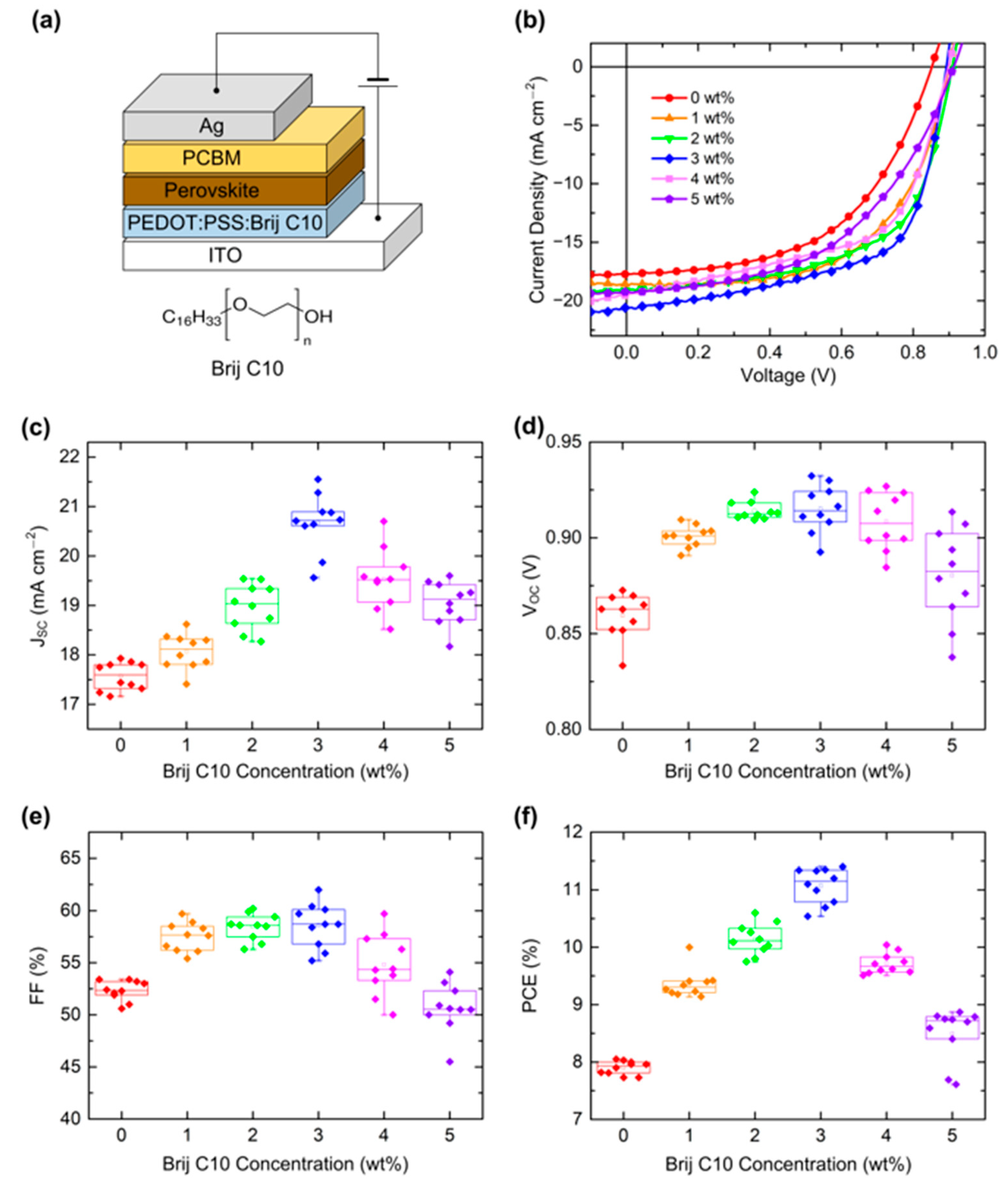
| Concentration | JSC (mA cm−2) | VOC (V) | FF (%) | PCE (%) |
|---|---|---|---|---|
| 0 wt% | 17.75 (17.57 ± 0.27) | 0.85 (0.86 ± 0.01) | 53.2 (52.33 ± 0.92) | 8.05 (7.90 ± 0.11) |
| 1 wt% | 18.62 (18.07 ± 0.34) | 0.90 (0.90 ± 0.01) | 59.7 (57.50 ± 1.32) | 10.00 (9.36 ± 0.23) |
| 2 wt% | 19.08 (18.98 ± 0.44) | 0.91 (0.91 ± 0.01) | 60.2 (58.45 ± 1.20) | 10.45 (10.14 ± 0.26) |
| 3 wt% | 20.61 (20.67 ± 0.56) | 0.89 (0.92 ± 0.03) | 62.0 (58.59 ± 2.01) | 11.40 (11.07 ± 0.29) |
| 4 wt% | 19.51 (19.52 ± 0.59) | 0.90 (0.91 ± 0.01) | 57.3 (54.83 ± 2.80) | 10.04 (9.71 ± 0.17) |
| 5 wt% | 19.26 (19.05 ± 0.42) | 0.91 (0.88 ± 0.02) | 50.0 (50.67 ± 2.23) | 8.80 (8.49 ± 0.44) |
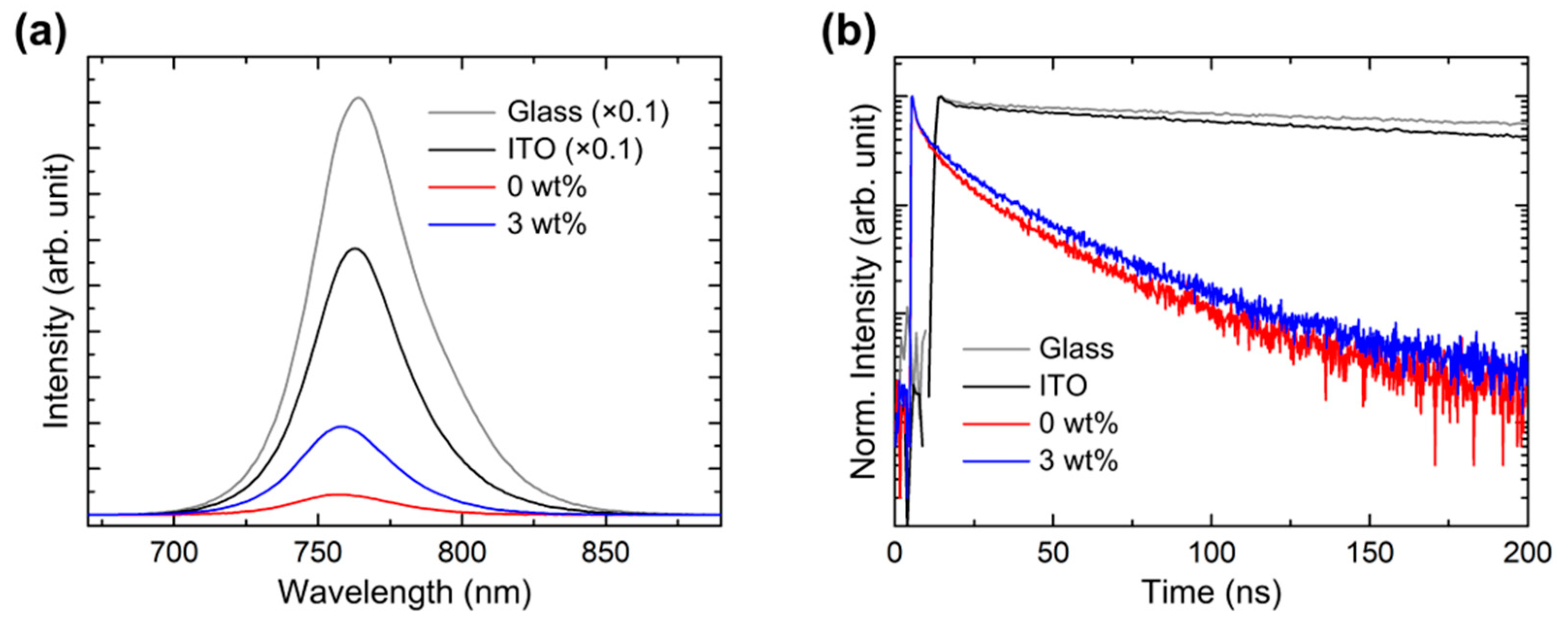
| A1 | τ1 (ns) | A2 | τ2 (ns) | A3 | τ3 (ns) | τavg (ns) | |
|---|---|---|---|---|---|---|---|
| Glass | 0.16 | 0.42 | 0.57 | 27.47 | 99.27 | 464.92 | 464.77 |
| ITO | 0.40 | 1.64 | 9.04 | 118.93 | 90.57 | 378.06 | 370.16 |
| 0 wt% | 5.21 | 1.14 | 32.49 | 7.90 | 62.30 | 30.18 | 27.43 |
| 3 wt% | 5.27 | 1.28 | 31.04 | 10.97 | 63.69 | 33.48 | 30.30 |
Disclaimer/Publisher’s Note: The statements, opinions and data contained in all publications are solely those of the individual author(s) and contributor(s) and not of MDPI and/or the editor(s). MDPI and/or the editor(s) disclaim responsibility for any injury to people or property resulting from any ideas, methods, instructions or products referred to in the content. |
© 2023 by the authors. Licensee MDPI, Basel, Switzerland. This article is an open access article distributed under the terms and conditions of the Creative Commons Attribution (CC BY) license (https://creativecommons.org/licenses/by/4.0/).
Share and Cite
Jung, S.; Choi, S.; Shin, W.; Oh, H.; Oh, J.; Ryu, M.-Y.; Kim, W.; Park, S.; Lee, H. Enhancement in Power Conversion Efficiency of Perovskite Solar Cells by Reduced Non-Radiative Recombination Using a Brij C10-Mixed PEDOT:PSS Hole Transport Layer. Polymers 2023, 15, 772. https://0-doi-org.brum.beds.ac.uk/10.3390/polym15030772
Jung S, Choi S, Shin W, Oh H, Oh J, Ryu M-Y, Kim W, Park S, Lee H. Enhancement in Power Conversion Efficiency of Perovskite Solar Cells by Reduced Non-Radiative Recombination Using a Brij C10-Mixed PEDOT:PSS Hole Transport Layer. Polymers. 2023; 15(3):772. https://0-doi-org.brum.beds.ac.uk/10.3390/polym15030772
Chicago/Turabian StyleJung, Sehyun, Seungsun Choi, Woojin Shin, Hyesung Oh, Jaewon Oh, Mee-Yi Ryu, Wonsik Kim, Soohyung Park, and Hyunbok Lee. 2023. "Enhancement in Power Conversion Efficiency of Perovskite Solar Cells by Reduced Non-Radiative Recombination Using a Brij C10-Mixed PEDOT:PSS Hole Transport Layer" Polymers 15, no. 3: 772. https://0-doi-org.brum.beds.ac.uk/10.3390/polym15030772