Article

Multioutlet Hydrants in Mediterranean Pressurized Irrigation Networks: Operation Problems and Hydraulic Characterization

by
Iban Balbastre-Peralta
1,
Jaime Arviza-Valverde
2,
Carmen Virginia Palau
1,*,
Cesar González-Pavón
2 and
Juan Manzano-Juárez
1
1
Centro Valenciano de Estudios del Riego, CVER, Universitat Politècnica de València, Camí de Vera s/n, 46022 València, Spain
2
Rural Engineering Departament, Universitat Politècnica de València, Camí de Vera s/n, 46022 València, Spain
*
Author to whom correspondence should be addressed.
Submission received: 6 September 2021 / Revised: 29 October 2021 / Accepted: 1 November 2021 / Published: 5 November 2021
(This article belongs to the Special Issue Modernization and Optimization of Irrigation Systems)

Abstract

:
Multioutlet hydrants as joint network infrastructure remain briefly addressed in the literature. Studies have always been limited to the individual treatment of the hydraulic components but not as a whole element. This study presents the main problems in the field of multioutlet hydrants within hydraulic infrastructure for pressure irrigation networks in Mediterranean agriculture. First, a field study with interviews was carried out in 30 water users associations (WUAs) between 2010 and 2018. Following this study, a laboratory test methodology was proposed to characterize this type of hydrant. Subsequently, four laboratory tests were performed on 12 multioutlet hydrants with different and common configurations found in irrigation networks: (i) head losses produced, (ii) global measurement precision in the multioutlet hydrant, (iii) blockage analysis in meters in vertical orientation, and (iv) hydrant behavior in response to hydraulic transients. The tests show that a horizontal configuration of the measuring elements with fewer than ten outlets and a suitable dimensioning of elements improve element maneuverability, instrument metrology, and irrigation emission uniformity. Finally, the importance of adequate design, dimensioning, and maintenance of the multioutlet hydrant devices is evidenced as a key point for the adequate management of collective pressure irrigation networks.

1. Introduction

The modernization of pressure irrigation systems in Mediterranean agriculture is a recent trend that has led to the installation of an infrastructural series that enables the control and management of irrigation water, moving from traditional irrigation systems such as surface irrigation to automated pressure systems for water distribution [1,2,3].
This irrigation modernization aims to achieve some advantages: (a) reduce water losses in transport and distribution networks, (b) irrigate all types of topographies, (c) bill the water consumed by each farmer, (d) increase efficiency and control in the use of water in microirrigation, and (e) achieve smart irrigation through the use of sensors [4,5,6,7].
In the Mediterranean area, the production model is based on intensive agriculture of small plots that average approximately 0.5 to 1 ha. The Valencia region is located in the east of Spain and covers a total of 300.417 ha of irrigated area, approximately 55.6% of the total cultivated area. Mainly, the cultivation of citrus fruits (52%), other fruits (15%), vineyards (9%), olive trees (4%), and other crops such as rice and vegetables (25%) predominate [8]. Currently, 72% of the irrigated surface corresponds to pressurized irrigation systems and the remaining 28% to surface irrigation [9]. Agriculture in this area is predominantly smallholding and mostly managed by water users associations (WUAs) that have modernized their irrigation systems through regional and national subsidies since 1995 [10,11].
The design of pressurized irrigation networks is simplified with the use of multioutlet hydrants. This type of hydrant groups all the water control elements and the automatic management of several plots into a single connection point in the network (Figure 1a) [12,13,14].
Currently, the location of these irrigation control systems is chosen using geographic information systems under the criteria of distance to the plots, elevation, or accessibility to the infrastructure (Figure 1b). Additionally, under technical–economic criteria, some mathematical optimization studies have been advanced that achieve efficient, spatially distributed multioutlet hydrants on the irrigated plots [15,16].
The European Standard EN 14267: Irrigation techniques—Irrigation hydrants (2004) [17] defines this infrastructure as an integrated valve system designed to ensure the supply of water in irrigation pressure networks. These hydrants include at least the functions of supply shut-off and water volume metering, although they can also limit the flow and regulate the pressure.
Multioutlet hydrants integrate these functions and manage the irrigation operation of various plots. They contain a main pipe or body of the hydrant connected to the pressurized network, together with a group of outlet intakes where individual meters and solenoid valves are installed to supply water to the end user. The configuration of multioutlet hydrants is highly variable, as shown in Figure 2. They can combine different elements of measurement, filtration, control valves, and pipes inside cast concrete sheds [18].
The standard does not define or detail the special characteristics of these multioutlet hydrants. This fact makes it impossible to apply many of the aspects and verification tests. The EN 14267 standard does not clarify how to treat the elements of the hydrant, whether as a whole or individually. Moreover, it does not clearly identify the differences between a single-outlet and multioutlet hydrant.
Consequently, the operation of these multioutlet hydrants as joint infrastructure is not well discussed in the literature. Previous studies have almost exclusively focused on single treatment of the elements of which they are composed, such as water meters, irrigation valves, or filters [19,20,21,22,23,24].
In this sense, the design and configuration of multioutlet hydrants mainly affect hydraulic parameters such as pressure head loss and outlet flow rates. Adequate pressure in the multioutlet hydrant implies good emission uniformity in the irrigation plots supplied.
The incorrect operation of these multioutlet hydrants can lead to problems in the management of the irrigation network. A failure in the data acquisition systems leads to the inefficient use of water by the farmer and the poor technical management of collective irrigation communities [25,26]. The volumes recorded by the meters are essential to achieve the efficient use of irrigation by controlling the consumption of each user [27,28,29,30].
To fill this literature gap, this paper studies the current state of multioutlet hydrants in pressurized irrigation networks in the Mediterranean region through visits to water users associations (WUAs). Subsequently, hydraulic behavior was characterized in the laboratory to identify the critical points in system configuration and design. The study will enable adapting the EN 14267 standard to this type of hydrant so that performance, configuration, and quality standards can be guaranteed.

2. Materials and Methods

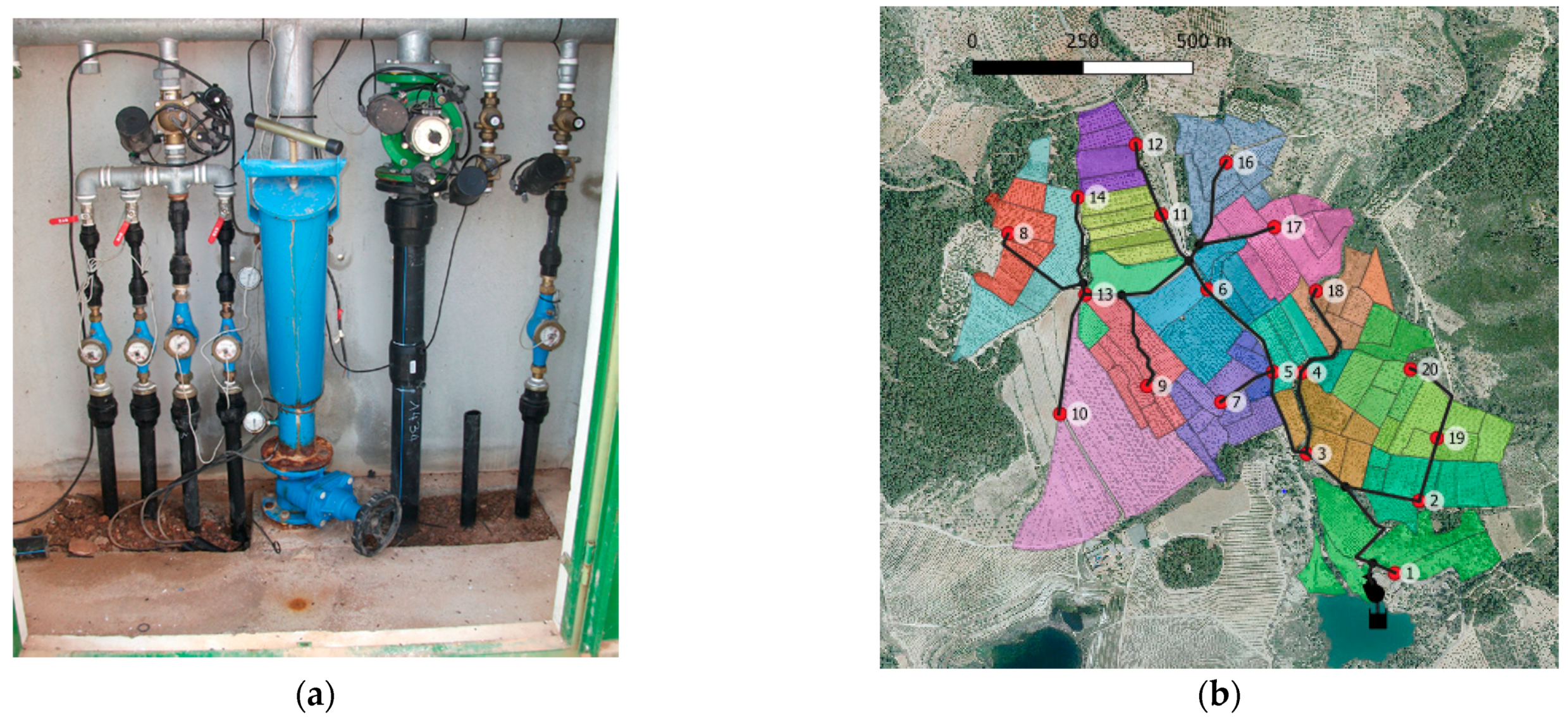
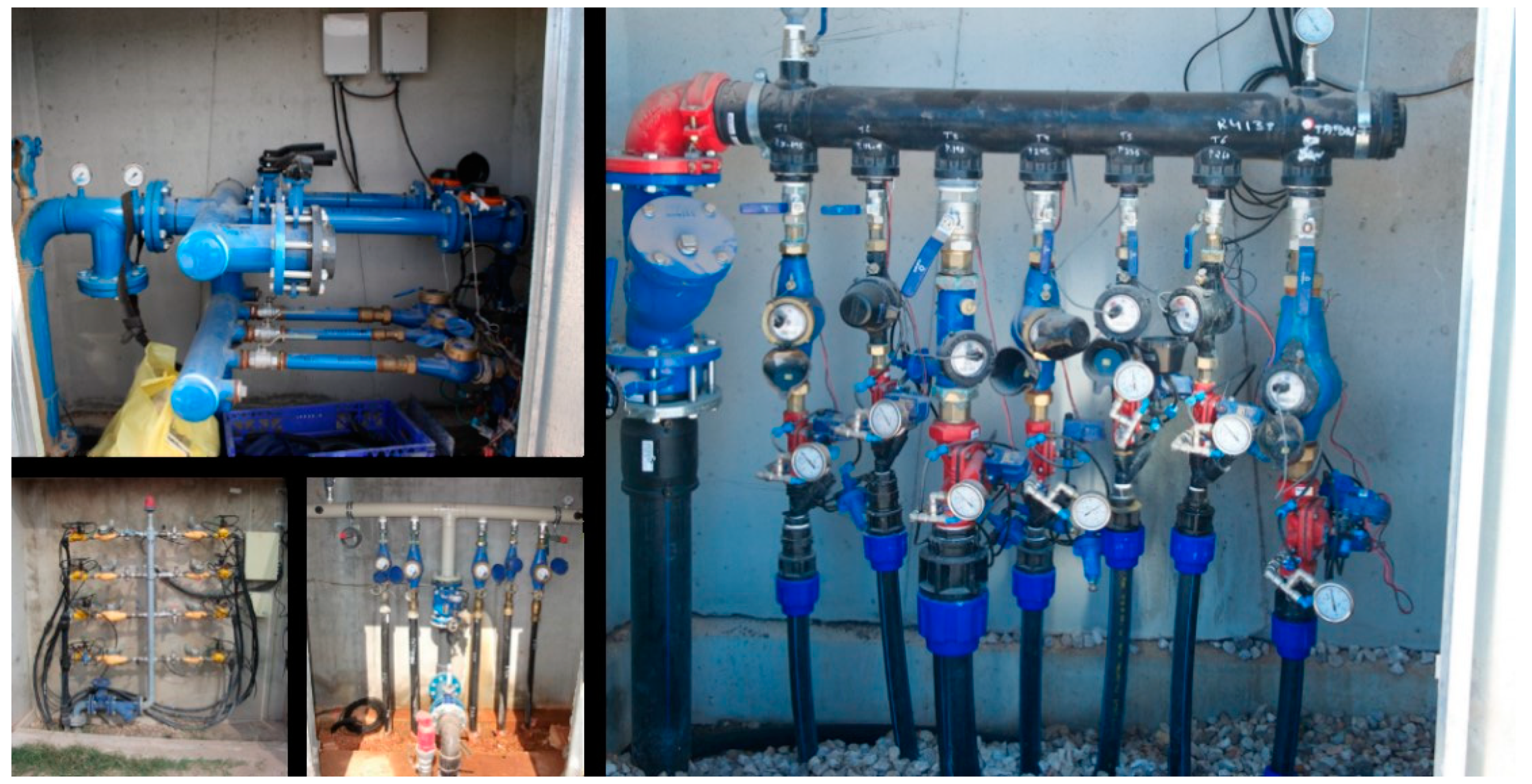
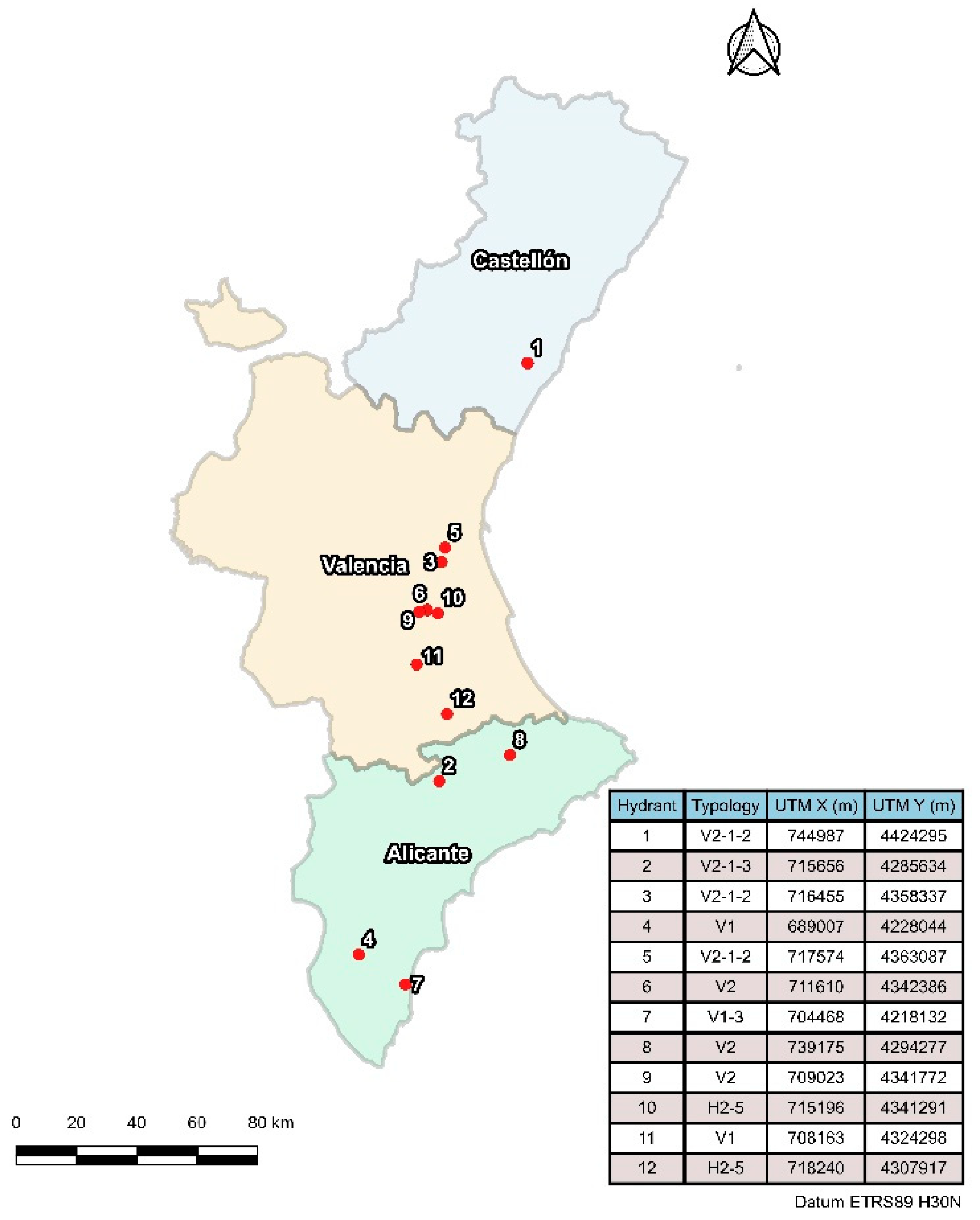
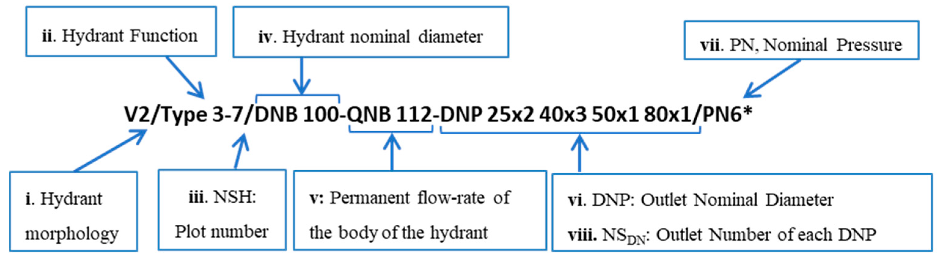
2.1. Multioutlet Hydrants in Irrigation Networks

In 2010, the operation of these systems began to be evaluated in a total of 30 WUAs, detecting that one of the main problems was in the management and operation of multioutlet hydrants [25]. Consequently, the most important problems affecting the operation of these infrastructures were identified.
The study area focused on the Valencian Community. The distribution of WUAs can be seen in Figure 3.
Data collection was carried out by running interviews with the WUAs’ managers. The manager was elected by the members of the WUA. The profile of the interviewees were males between 50 and 70 years of age with many years of agricultural and technical experience. Data were collected in 2010 and 2016 to analyze the evolution of the technological modernization of drip irrigation systems [25].
The methodology is based on an interpretative research paradigm [31]. Qualitative research methods were used to obtain information and to organize the explanations of the different managers. It can be affirmed that the interviews provide a qualitative vision of the problems of multioutlet hydrants in terms of maneuvering, accessibility, blocking of instruments, etc. Subsequently, it should be contrasted with the hydraulic operation of the entire infrastructure in the laboratory where problems detected by users in WUAs are confirmed.
During the field study, the configurations found for these types of hydrants were very diverse in the number of intakes, position of the hydraulic elements, and components used. To identify each type of multioutlet hydrant, the code shown in Figure 4 is proposed.
Configuration of these hydrants will be defined through the following parameters:
i. Hydrant morphology: indicates the configuration based on the arrangement of general elements and water meters in vertical (V) or horizontal (H) orientations and the connection point of the network to the hydrant: lateral (1) or central (2);
ii. Hydrant function: defined according to the classification described in the EN 14267 (2004) [17] standard and shown in Table 1.
iii. Number of intakes (NSH): corresponds to the number of plots irrigated;
iv. Nominal diameter of body and main elements in millimeters (DNB);
v. Nominal hydrant flow in m3 h–1 (QNB). Sum of the QNP of each outlet. Nominal flow of each outlet in m3 h–1 (QNP), based on their permanent flow;
vi. Nominal diameter (DNP) of the outlets, in millimeters: indicates the DN of the water measurement element installed at the outlet;
vii. Nominal pressure (PN) in bar or kPa, choice of the element with the lowest pressure from the set of hydrant elements;
viii. Number of outlets of each DNP (NSDN).

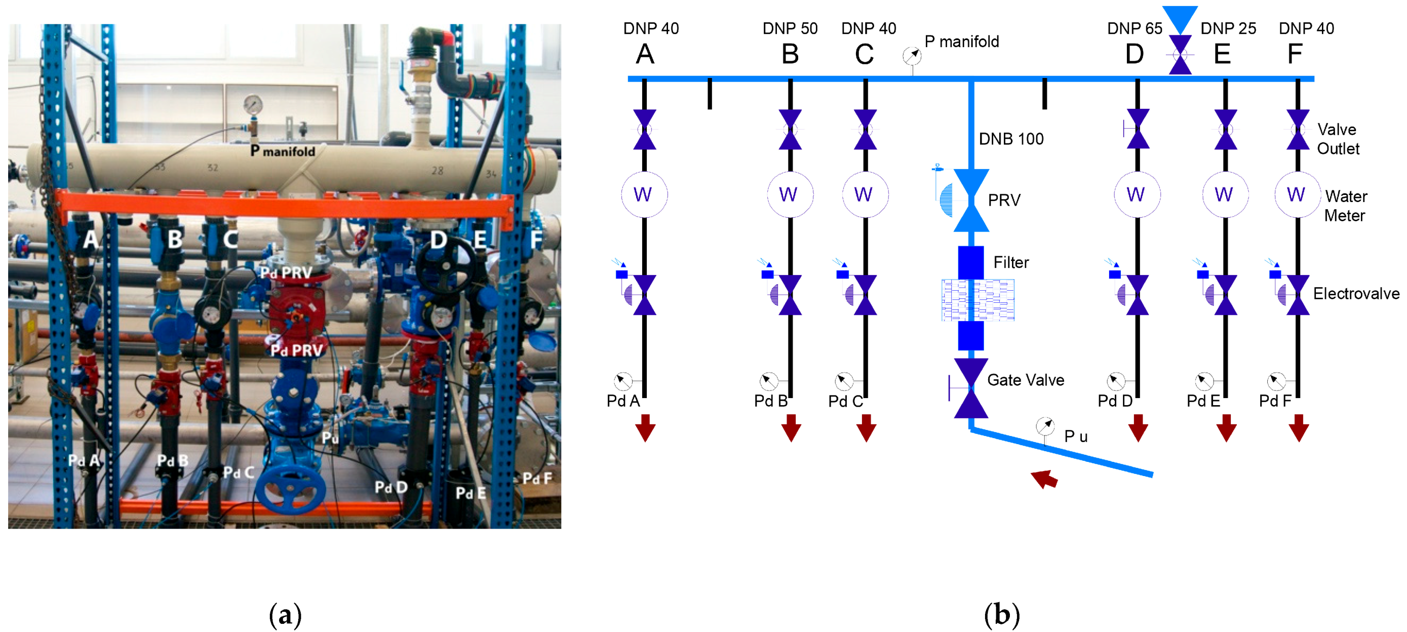
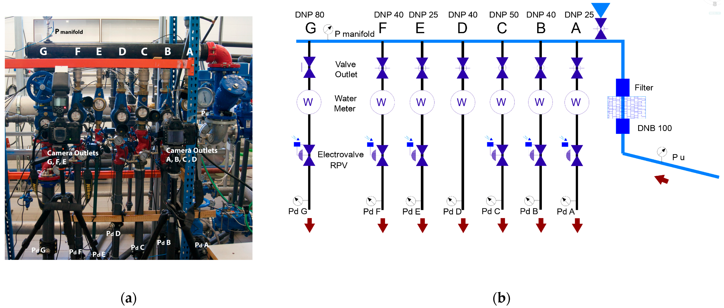
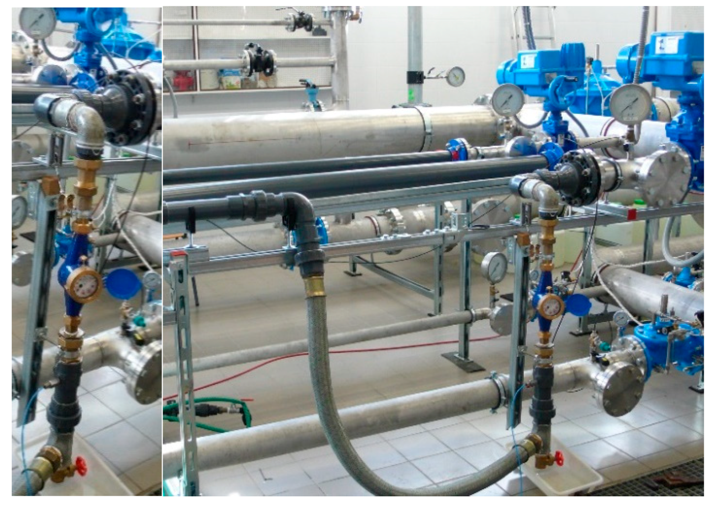
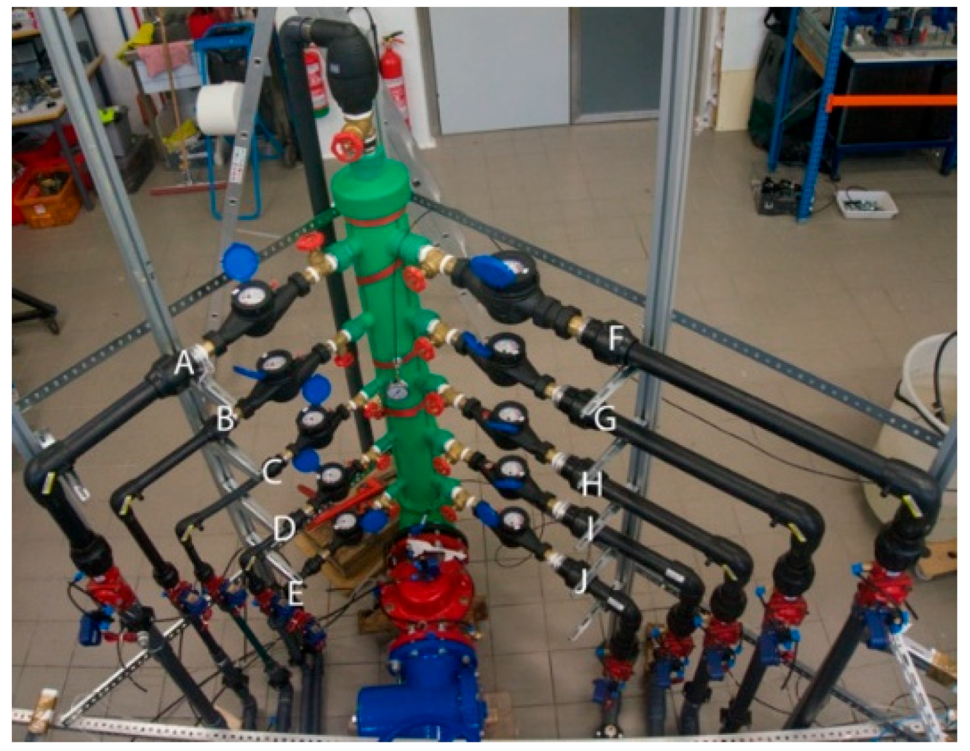
2.2. Multioutlet Hydrant in Laboratory

In this work, the hydraulic characterization of 12 new multioutlet hydrants was carried out with the most common configurations found in the field (Table 2). Approximately 85% of the multioutlet hydrants found in the WUAs had DNB between 80 and 150 mm, which supplied 3 to 10 intakes, serving, each one, an average plot area of 0.75 ha.
The tests show the behavior of hydrants installed in the field in extreme situations: the head loss generated by the infrastructure, the accuracy of the measuring instruments within each configuration, the blocking metering problems, and finally, the possible hydraulic transients in the opening and closing maneuver of the irrigation intakes.
The four experiments are presented in a flowchart (Figure 5) and were carried out between 2010 and 2016 at the Hydraulic and Irrigation Laboratory (LHIR) of the Universitat Politècnica de València. The main characteristics of the test bench are:
  • Pumping station with three 33 kW variable-speed pumps;
  • Closed circuit with double tank (2000 L and 15,000 L);
  • Reference electromagnetic flowmeters DN25, DN50, DN100, and DN200, with an accuracy of 0.5%, calibrated by weighing;
  • Data acquisition system developed in LabView (2015) for the control of time, temperature, flow, and pressure variables;
  • Control bench with 16 variable-range pressure transducers and 4 differential pressure transducers.

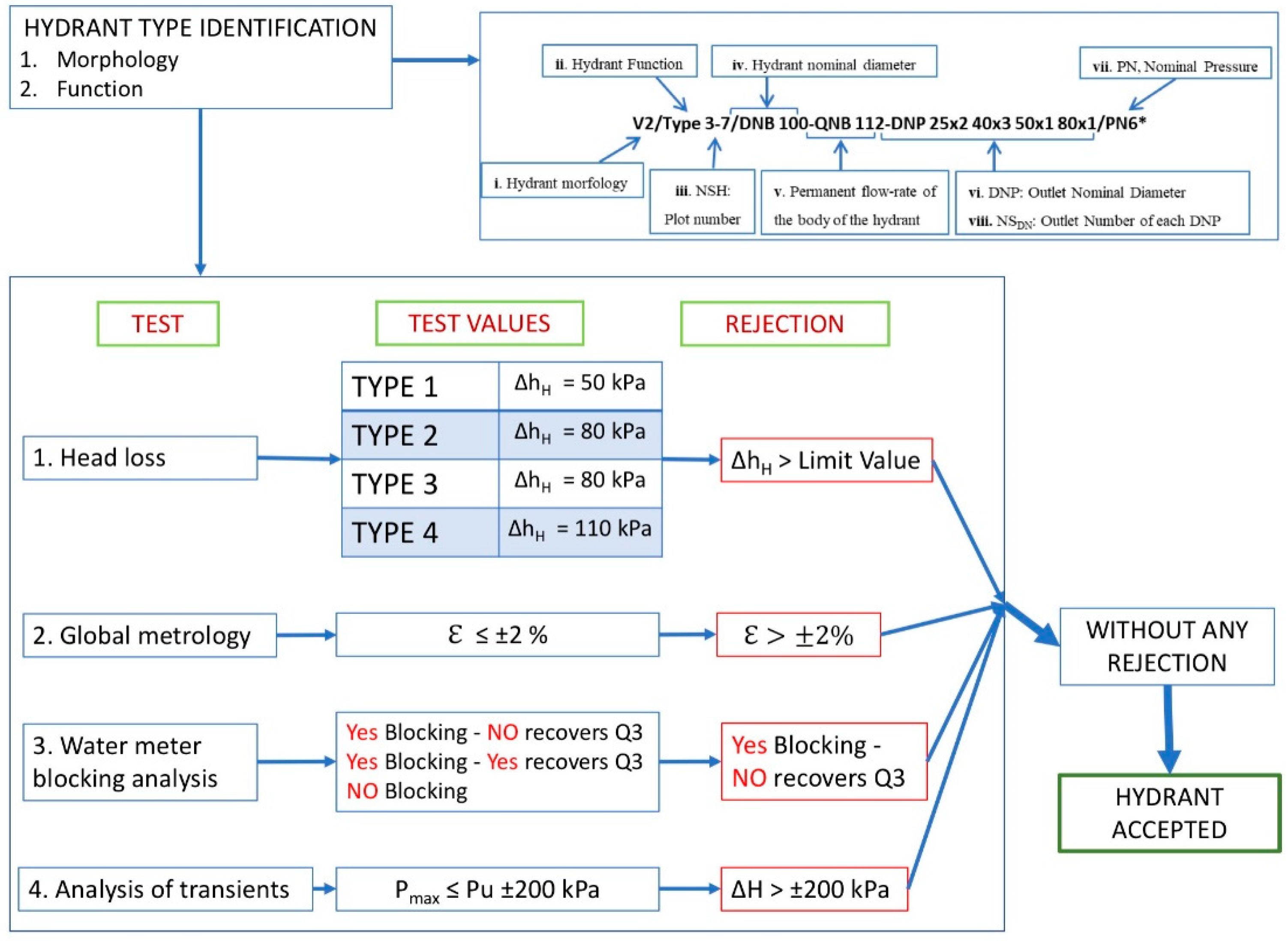
2.2.1. Head Loss of the Multioutlet Hydrant

In this test, head losses of twelve multioutlet hydrant configurations that regulate the operation of the downstream irrigation system were determined. The test was carried out with all the plot intakes open, and the flow rate of each intake was regulated approximately at QNP. The multioutlet hydrant number 9 test bench is shown in Figure 6a.
The EN 14267 [17] standard indicates that head losses must be obtained through the EN 1267 standard, which cannot be applied due to the combination of different elements in a small space, and it is impossible to guarantee the straight sections specified by the standard. Therefore, the head loss (∆hH) was determined by the pressure difference between the connection to the distribution network and the connection to each user for the QNB of the body hydrant and the QNP of the outlets (Figure 6b).
Δ h H = P u P dx
where Pu is the pressure at the inlet of the multioutlet hydrant (kPa), and Pdx is the pressure at the outlet of each intake (kPa).
By having multiple outlets, the difference in kinetic heights between the inlet and the outlets is depreciated, because the speeds obtained are similar, and the error is less than the errors of the pressure sensors used.

2.2.2. Global Metrology of the Multioutlet Hydrant

Water meters are the most important and sensitive elements of the multioutlet hydrant, and their correct measurement is one of the objectives of these installations [32,33].
The measurement error is obtained from the measurement of the meter’s pulse emitter, where each pulse marks a consumed volume. This form of metering represents a real automation system in the field for billing consumption. As a second laboratory measurement, a sequential photographic comparison of the instrument’s totalizer to the launched water meter is made (minimum shutter speed of 1/60 s) (Figure 7a). The flow, in both cases, is obtained by differences in the volume and time used in each test. The test scheme for hydrant number 11 is shown in Figure 7b.
The EN 14267 standard [17] indicates how to test water meters in hydrants but does not specify anything about their testing position or the possible disturbing elements that may be downstream and upstream. In the case of multioutlet hydrants, these installation characteristics are very important. Additionally, the metrology of each water meter can be evaluated to globally check the metrological status of the whole hydrant.
The method is divided into two phases. First, the water meter is tested in its actual position in the hydrant, and the permanent flow (QNP) and accuracy are evaluated sequentially for each outlet.
After this test, the overall metrology is checked with all the outlets running at the same time. The accuracy of the water meters is globally compared in the multioutlet hydrants tested at their QNB. The flow rate of the hydrant close to QNB and in the intakes to QNP is regulated, and the flow rate of each intake is measured sequentially. The sum of the flow rates recorded in the intakes is compared with the average of the flow recorded continuously during the test by the electromagnetic flow meter of the bench. The reference flow rate of the electromagnetic flow meter (QEMF) remains constant throughout the test.
The sum of the flow measurements from the meters of each multioutlet hydrant is compared with the reference measurement of the test bench, and the overall error of the hydrant is determined:
ε = (   Q H Q EMF Q EMF ) ×   100 ,
where QH is the sum of the total flow of the multioutlet hydrant and QEMF is the flow measured with the electromagnetic or reference flow meter.

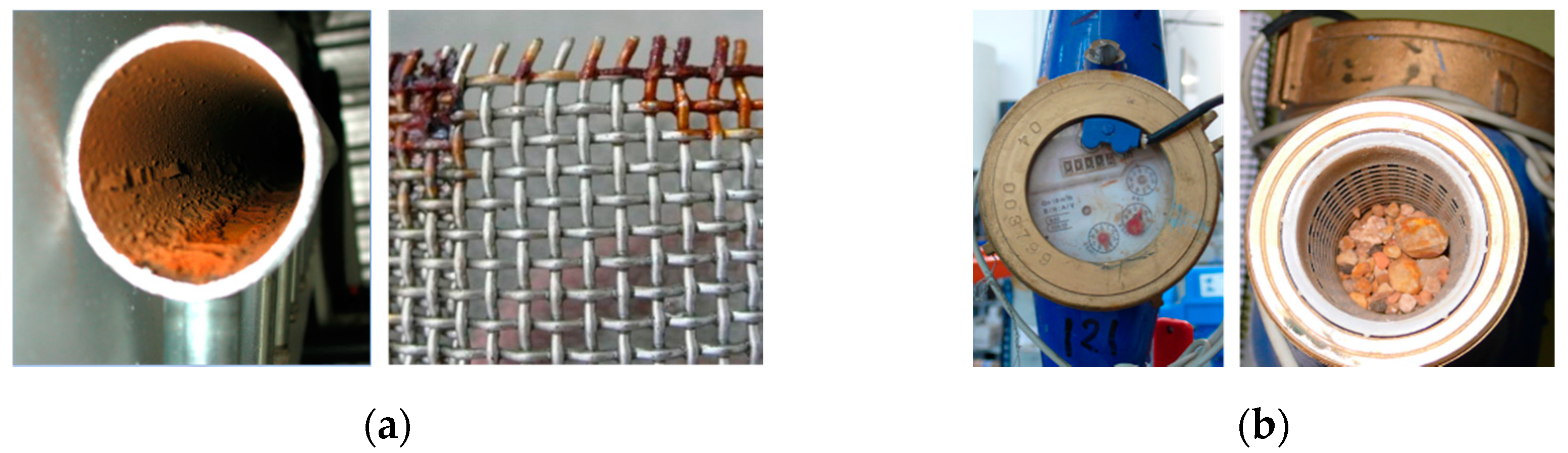
2.2.3. Water Meter Blocking Analysis

The phenomenon of meter blockage in many WUAs is a significant problem and is leading to massive changes in multijet water meters or to the elimination of the measurements of water consumed. Thus, WUAs start to bill the water by surface area and crop.
In multijet water meters, the turbine rotation speed depends on the impact speed of the water on it. When the flow rates are very high, the impact of the water flow will be greater, producing a decoupling in the magnetic transmission that connects the turbine with the meter’s totalizer. In this way, the totalizer remains blocked and, without movement, ceases to count the water consumed throughout the irrigation period [34].
However, in which cases do these abnormally high flow conditions occur? Generally, it is in situations where the pressure differential between the inlet and outlet of the instrument is high. This occurs during the filling of the pressure network, which is empty at the beginning of the irrigation period. In this situation, a pressure gradient that can usually reach 300–500 kPa causes very high flow rates, higher than the QNP. Consequently, the impact speeds of the water on the turbines are very high. This phenomenon was also verified in the field using real-time measurements (Figure 8).
To assess the magnitude of this problem, a second metrological test was performed. A total of 86 new multijet meters from DN15 to DN40 from various commercial manufacturers were evaluated.
The meters were tested independently and in a vertical position, as shown in Figure 9. They were tested for operation at high flow rates by exceeding their Q4 or overhead flow until it was doubled. The meter blocking was determined by the stop of the needles arranged in the instrument’s totalizer.

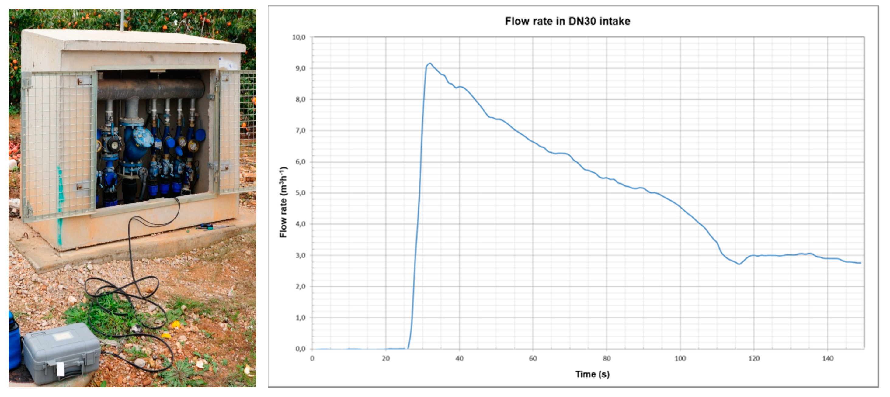
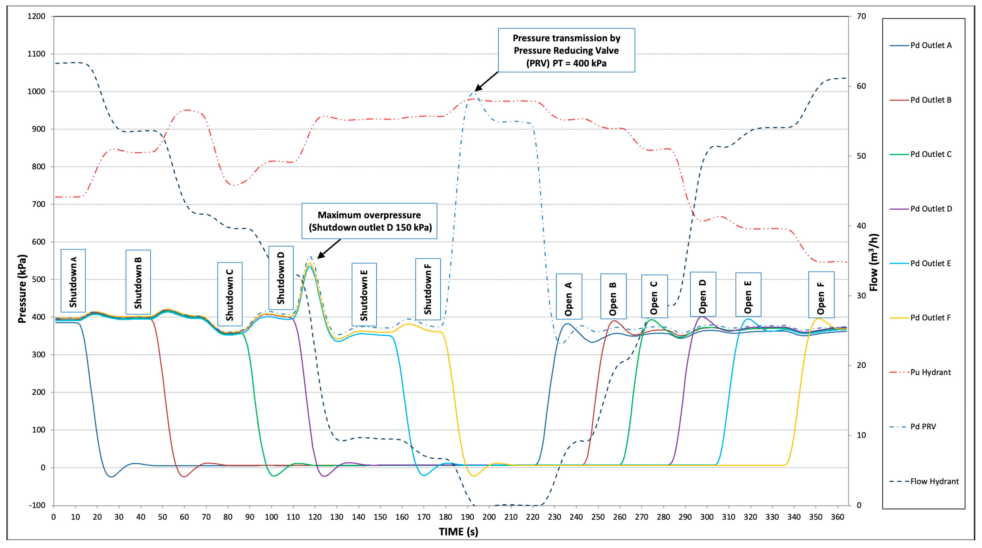
2.2.4. Analysis of Transients in the Opening and Closing of Irrigation Intakes

In automated irrigation networks, the intakes are opened and closed throughout the irrigation day. This fact generates a sequence of operation periods in a permanent and stable regime and intermediate periods of hydraulic transients. Depending on the opening and closing time and the size of the intake, the transient can generate structural and hydrant operation problems.
The test performed enabled simulation of the evolution of the pressure and flow rate of the hydrant in the maneuvering of opening and closing the intakes, simulating the starting and stopping of irrigation in a real situation in the field. The pressure is continuously recorded to visualize the transients caused by the closing and opening of the intakes.
The test was carried out with solenoid valves controlling the intakes and sequentially opening and closing. Sufficient time intervals were operated so that the pressure and flow rate values stabilized after each opening and closing.
The transient test described in the standard refers to a single-user hydrant, which makes it unfeasible to perform it with the configuration and characteristics of a multioutlet hydrant serving several users.

3. Results and Discussion

3.1. Main Problems Detected in Multioutlet Hydrant

The interviews focused on questions about irrigation management, automation, and problems in the management and the infrastructure of the WUAs. The problems found in the interviews were grouped into seven categories. Multioutlet hydrants were included as elements of maneuver, regulation, and protection of the network. In this group, it was detected that 79% of WUAs are affected. When analyzing each category, it was observed that the most important problems are related to the blocking of flow meters (29%) and malfunction in shut-off valves (29%) in multioutlet hydrants [25].
Table 3 lists the weaknesses found in this type of infrastructure after the qualitative field study.
Figure 10a shows rust in metallic elements of the hydrant caused by poor-quality materials. Figure 10b points out the lack of maintenance in water meters due to the low quality of irrigation water.

3.2. Behavior in the Laboratory

One concern about the interview findings was to control the hydraulic operation behavior in laboratory tests. Results in 12 different morphologies of hydrants are exposed.

3.2.1. Multioutlet Hydrant Head Loss

The test results indicated whether the hydrant was well configured, and its elements were well chosen. Table 4 summarizes the results of all hydrants tested. Only four of the twelve accomplished the head loss limits established by the standard EN 14267 [17].
The causes were different depending on the configuration and the elements chosen:
  • Hydrant 1 had a poor choice of hydrant elements, and general elements were of smaller dimensions than recommended.
  • Hydrant 2 did not have solenoid valves in the intakes; therefore, the results showed fewer head losses than the maximum recommended.
  • Hydrant 3 introduced high head loss due to inadequate selection of the solenoid valves of each intake.
  • Hydrants 5 and 10 slightly exceeded the head losses established by the standard, but no configuration problems were observed.
  • Hydrants 4, 6, and 12 complied with the standard.
  • Hydrant 7 had flow limiters incorrectly selected, causing excessive head loss.
  • In Hydrant 8, it was observed that the meters of that manufacturer in the DNP 30 mm intakes generated very high head losses.
  • All the elements in Hydrant 11 were undersized for the number of intakes and their DNP, which produced higher head losses.
The results demonstrate an inadequate selection of the main elements of the multioutlet hydrant, which caused high head losses in the entire hydrant, ranging between 53 and 192 kPa. It is important to limit head losses produced by hydrants to reduce energy costs and achieve greater emission irrigation uniformity in irrigation subunits [35,36].

3.2.2. Global Hydrant Metrology

The results obtained from this test are shown in Table 5. Global errors in hydrants are acceptable within the thresholds of ±2% marked in the International Standard ISO 4064-1: 2014 [37] and the international recommendations OIML R49 [38] for flow rates between the transition flow (Q2) and overload flow (Q4) with temperatures below 30 °C.
Greater errors were only seen in those hydrants that included a Woltman meter in some of their outlets. Several studies report that water meter technology is sensitive to water flow perturbations [39,40].

3.2.3. Blocking Effect Analysis

The results obtained show that the blocking phenomenon is usual in multijet meters installed in a vertical position (Table 6). This technology and type of installation is the most common in Mediterranean multioutlet hydrants. Water meter sizes from DN15 to DN30 in a vertical position are those that have the most blocking problems due to the displacement of the meter turbine.

3.2.4. Analysis of Transients in the Opening and Closing of Irrigation Intakes

The transients recorded were usually moderate, causing overpressures (ΔH) of less than 150 kPa in most cases (Table 7). These values indicate that this phenomenon is not a problem in this type of facility.
Figure 11 shows the evolution of pressure before the closures and openings of the different irrigation intakes of the hydrant. Pressure and flow were recorded every 0.5 s. The closures of the intakes produced slight increases in pressure in all parts of the hydrant and slight depressions in the closed outlets. Transients were higher when the relationship between the hydrant flow rate (QNB) and the closed outlet (QNP) was lower, as can be seen in the closure of outlet D (QNB/QNP = 73.5/25). Even so, the transients were moderate, and in this case, 150 kPa.
It was also observed in the pressures of the general elements that the pressure reducing valve (PRV) of the hydrant was not capable of protecting the installation at the moment of closure, transmitting the pressure to all the hydrant elements. In the process of outlet opening (irrigation start), the overpressure was lower and not very significant.

3.3. Configuration and Design Proposal

The tests carried out and problems detected facilitated the design of a multioutlet hydrant to reduce these problems (Figure 12). The configuration of Hydrant 12 is the result of the application of this design, and the hydraulic characterization and quality of the elements are described as follows:
i. The horizontal meters avoid meter blocking at any flow rate.
ii. The straight upstream and downstream sections guarantee metering throughout the useful life of the meters, regardless of the type of meter chosen.
iii. The selection of DNBs based on the QNB of the hydrant is valid, being verified in the head loss results (Table 4).
iv. The number and position of the elements in the hydrant enable the correct handling of them, facilitating maintenance and repair works.
v. The placement of the stone catcher filter enables cleaning and guarantees the retention of the filtered elements.
vi. The use of thermoplastic materials eliminates the risks of oxidation and avoids vandalism.

4. Conclusions

In summary, this paper argued the current problems faced by multioutlet hydrants installed in irrigation networks in the Mediterranean region. The main problems encountered are the management, maintenance, selection, and configuration of this type of hydrant. As in any installation, the maintenance of elements and replacement of those that have deteriorated will improve the hydraulic performance of the hydrant.
Initially, with a qualitative study, it is detected that the malfunction of hydrants is a general problem in the WUAs network. Afterwards, laboratory tests allow evaluating the magnitude of the problem in different types of hydrant configurations.
Test results showed problems in underdimensioned electrovalves and water meters that generate inadmissible head losses. The Woltman water meter installed in hydrant outlets presented measuring errors. DN15 to DN30 multijet water meters placed in vertical positions suffer blockages in the measurement of the water consumed. These findings recommended to consider, during the network project phase, these proposals.
The most satisfactory results are obtained with a configuration similar to hydrant 12. This recommends a maximum number of intakes, 10, and the hydraulic elements of the intakes are arranged horizontally. It has a vertically positioned inlet manifold that allows correct maneuverability and accessibility for the maintenance of all its devices. These adequate criteria will increase the hydrant lifetime and will reduce maintenance and energy costs for the irrigation communities.
In conclusion, this study reveals that critical elements for the proper functioning of the network, such as multioutlet hydrants, are not given the attention they require. The adequation of standard EN 14267 considering this infrastructure is needed. Future research should examine the hydrant design process by using simulation tools and hydraulic analysis validation to guarantee the correct operation.

Author Contributions

Conceptualization, I.B.-P. and J.A.-V.; methodology, I.B.-P.; software, I.B.-P. and C.G.-P.; validation, I.B.-P., C.V.P. and J.M.J.; formal analysis, C.G.-P. and C.V.P.; investigation, I.B.-P. and J.M.J.; resources, I.B.-P. and J.M.J.; data curation, I.B.-P. and C.V.P.; writing—original draft preparation, C.V.P., C.G.-P. and I.B.-P.; writing—review and editing, J.M.J. and I.B.-P.; visualization, C.G.-P.; supervision, J.A.-V. All authors have read and agreed to the published version of the manuscript.

Funding

This research received no external funding.

Conflicts of Interest

The authors declare no conflict of interest.

References

  1. Abadia, R.; Rocamora Osorio, C.; Ruiz, A.; Puerto, H. Energy Efficiency in Irrigation Distribution Networks I: Theory. Biosyst. Eng. 2008, 101, 21–27. [Google Scholar] [CrossRef]
  2. Lecina, S.; Isidoro, D.; Playán, E.; Aragüés, R. Irrigation Modernization and Water Conservation in Spain: The Case of Riegos Del Alto Aragón. Agric. Water Manag. 2010, 97, 1663–1675. [Google Scholar] [CrossRef] [Green Version]
  3. Tarjuelo, J.M.; Rodriguez-Diaz, J.A.; Abadía, R.; Camacho, E.; Rocamora, C.; Moreno, M.A. Efficient Water and Energy Use in Irrigation Modernization: Lessons from Spanish Case Studies. Agric. Water Manag. 2015, 162, 67–77. [Google Scholar] [CrossRef]
  4. Ortega-Reig, M.; Sanchis-Ibor, C.; Palau-Salvador, G.; García-Mollá, M.; Avellá-Reus, L. Institutional and Management Implications of Drip Irrigation Introduction in Collective Irrigation Systems in Spain. Agric. Water Manag. 2017, 187, 164–172. [Google Scholar] [CrossRef]
  5. García-Molla, M.; Ortega-Reig, M.V.; Sanchis-Ibor, C.; Avellá-Reus, L. The effects of irrigation modernization on the cost recovery of water in the Valencia Region (Spain). Water Sci. Technol-W Sup. 2014, 14, 414–420. [Google Scholar] [CrossRef] [Green Version]
  6. Playán, E.; Mateos, L. Modernization and Optimization of Irrigation Systems to Increase Water Productivity. Agric. Water Manag. 2006, 80, 100–116. [Google Scholar] [CrossRef] [Green Version]
  7. Lamaddalena, N.; Sagardoy, J.A. Performance Analysis of On-Demand Pressurized Irrigation Systems; FAO: Rome, Italy, 2000. [Google Scholar]
  8. GVA. Informe Del Sector Agrari Valencià 2019: València: Generalitat Valenciana. Available online: http://www.agroambient.gva.es/va/informes-del-sector-agrario-valenciano (accessed on 25 October 2021).
  9. INE. Encuesta de Superficies y Rendimientos de Cultivos de España; Instituto Nacional de Estadística: Madrid, Spain, 2020; Available online: https://www.mapa.gob.es/es/estadistica/temas/estadisticas-agrarias/agricultura/esyrce (accessed on 10 May 2021).
  10. Sanchis-Ibor, C.; Ortega-Reig, M.; Guillem-García, A.; Carricondo, J.M.; Manzano-Juárez, J.; García-Mollá, M.; Royuela, Á. Irrigation Post-Modernization. Farmers Envisioning Irrigation Policy in the Region of Valencia (Spain). Agriculture 2021, 11, 317. [Google Scholar] [CrossRef]
  11. INE. Censo Agrario 2009; Instituto Nacional de Estadística (Statistics National Institute): Madrid, Spain, 2011; Available online: http://www.pegv.gva.es/es/temas/agriculturaganaderiaselviculturacazapescayacuicultura/censoagrario/censoagrario2009 (accessed on 25 October 2021).
  12. Jiménez-Bello, M.Á.; Alzamora, F.M.; Castel, J.R.; Intrigliolo, D.S. Validation of a Methodology for Grouping Intakes of Pressurized Irrigation Networks into Sectors to Minimize Energy Consumption. Agric. Water Manag. 2011, 102, 46–53. [Google Scholar] [CrossRef]
  13. Moreno, M.A.; Córcoles, J.I.; Tarjuelo, J.M.; Ortega, J.F. Energy Efficiency of Pressurised Irrigation Networks Managed On-Demand and under a Rotation Schedule. Biosyst. Eng. 2010, 107, 349–363. [Google Scholar] [CrossRef]
  14. Rodríguez-Díaz, J.A.R.; Pérez-Urrestarazu, L.P.; Camacho-Poyato, E.C.; López-Luque, R.L. IGRA. A Tool for Applying the Benchmarking Initiative to Irrigated Areas. Irrig. Drain. 2005, 54, 307–319. [Google Scholar] [CrossRef]
  15. González-Villa, F.; García-Prats, A. Using Location-Allocation Algorithms to Distribute Multioutlet Hydrants in Irrigation Networks Design. J. Irrig. Drain. Eng. 2012, 138, 304–309. [Google Scholar] [CrossRef]
  16. Carrillo-Cobo, M.T.; Rodríguez-Díaz, J.A.; Montesinos, P.; López-Luque, R.; Camacho Poyato, E. Low Energy Consumption Seasonal Calendar for Sectoring Operation in Pressurized Irrigation Networks. Irrig. Sci. 2011, 29, 157–169. [Google Scholar] [CrossRef]
  17. European Committee for Standardization. European Committee for Standardization. European Standards EN 14267. In Irrigation Techniques-Irrigation Hydrants; European Committee for Standardization: Brussels, Belgium, 2004. [Google Scholar]
  18. Balbastre-Peralta, I.; Arviza, J.; Manzano, J.; Palau, C.V. Multioutlet Hydrants Typology for Collective Irrigation Networks. In Proceedings of the 19th CIGR World Congress (CIGR 2018), Antalya, Turkey, 22–26 April 2018; pp. 17–27. [Google Scholar]
  19. Palau, C.V.; Balbastre, I.; Manzano, J.; Azevedo, B.M.d.; Bomfim, G.V.d. Metrological behaviour of bulk water meters under diverse installation configurations. Eng. Agríc. 2018, 38, 893–900. [Google Scholar] [CrossRef]
  20. Varatharajalu, K.; Ramprabu, J. Wireless Irrigation System via Phone Call & SMS. Int. J. Eng. Adv. Technol. 2018, 8, 397–401. [Google Scholar]
  21. Wu, W.-Y.; Huang, Y.; Liu, H.-L.; Yin, S.-Y.; Niu, Y. Reclaimed Water Filtration Efficiency and Drip Irrigation Emitter Performance with Different Combinations of Sand and Disc Filters. Irrig. Drain. 2015, 64, 362–369. [Google Scholar] [CrossRef]
  22. Coates, R.W.; Delwiche, M.J.; Broad, A.; Holler, M. Wireless Sensor Network with Irrigation Valve Control. Comput. Electron. Agric. 2013, 96, 13–22. [Google Scholar] [CrossRef]
  23. Kim, Y.; Evans, R.G.; Iversen, W.M. Remote Sensing and Control of an Irrigation System Using a Distributed Wireless Sensor Network. IEEE Trans. Instrum. Meas. 2008, 57, 1379–1387. [Google Scholar] [CrossRef]
  24. Creaco, E.; Campisano, A.; Modica, C. Testing behavior and effects of PRVs and RTC valves during hydrant activation scenarios. Urban Water J. 2018, 15, 218–226. [Google Scholar] [CrossRef]
  25. González-Pavón, C.; Arviza, J.; Balbastre, I.; Carot-Sierra, J.M.; Palau-Salvador, G. Are Water User Associations Prepared for a Second-Generation Modernization? The Case of the Valencian Community (Spain). Water 2020, 12, 2136. [Google Scholar] [CrossRef]
  26. Perry, C.J.; Steduto, P.; Allen, R.; Burt, C. Increasing Productivity in Irrigated Agriculture: Agronomic Constraints and Hydrological Realities. Agric. Water Manag. 2009, 96, 1517–1524. [Google Scholar] [CrossRef] [Green Version]
  27. Fernández-Pacheco, D.G.; Ferrández-Villena, M.; Molina-Martínez, J.M.; Ruiz-Canales, A. Performance Indicators to Assess the Implementation of Automation in Water User Associations: A Case Study in Southeast Spain. Agric. Water Manag. 2015, 151, 87–92. [Google Scholar] [CrossRef]
  28. Stambouli, T.; Faci, J.M.; Zapata, N. Water and Energy Management in an Automated Irrigation District. Agric. Water Manag. 2014, 142, 66–76. [Google Scholar] [CrossRef] [Green Version]
  29. Cruz-Blanco, M.; Lorite, I.J.; Santos, C. An Innovative Remote Sensing Based Reference Evapotranspiration Method to Support Irrigation Water Management under Semi-Arid Conditions. Agric. Water Manag. 2014, 131, 135–145. [Google Scholar] [CrossRef]
  30. Jiménez-Bello, M.A.; Martínez Alzamora, F.; Bou Soler, V.; Ayala, H.J.B. Methodology for Grouping Intakes of Pressurised Irrigation Networks into Sectors to Minimize Energy Consumption. Biosyst. Eng. 2010, 105, 429–438. [Google Scholar] [CrossRef]
  31. Miles, M.B.; Huberman, A.M.; Saldaña, J. Qualitative Data Analysis: A Methods Sourcebook, 3rd ed.; Huberman, A.M., Saldaña, J., Eds.; Sage: Thousand Oaks, CA, USA, 2014; p. 381. ISBN 9781452257877. [Google Scholar]
  32. Burke, L.; Hannah, C. Improve Accuracy with Proper Water Meter Installation. Opflow 2010, 36, 18–21. [Google Scholar] [CrossRef]
  33. Arregui, F.; Jr, E.C.; Cobacho, R. Integrated Water Meter Management; IWA Publishing: London, UK, 2007. [Google Scholar]
  34. Palau, C.V.; Balbastre, I.; Arviza, J.; Sanchis-Alós, L.H. Bloqueo de contadores de chorro múltiple en hidrantes multiusuario para riego. In Proceedings of the 33th Congreso Nacional de Riegos, Valencia, Spain, 16–18 June 2015. [Google Scholar] [CrossRef] [Green Version]
  35. Wu, I.-P. An Assessment of Hydraulic Design of Micro-Irrigation Systems. Agric. Water Manag. 1997, 32, 275–284. [Google Scholar] [CrossRef]
  36. Pereira, L.S.; Oweis, T.; Zairi, A. Irrigation Management under Water Scarcity. Agric. Water Manag. 2002, 57, 175–206. [Google Scholar] [CrossRef]
  37. International Organization for Standardization. International Organization for Standardization. International Standard ISO 4064-1:2014. In Water meters for Cold Potable Water and Hot Water—Part 1: Metrological and Technical Requirements; International Organization for Standardization: Geneva, Switzerland, 2014. [Google Scholar]
  38. International Organization of Legal Metrology. OIML R 49-3:2013. In Water Meters for Cold Potable Water and Hot Water; International Organization of Legal Metrology: Paris, France, 2013. [Google Scholar]
  39. Simão, M.; Besharat, M.; Carravetta, A.; Ramos, H.M. Flow velocity distribution towards flowmeter accuracy: CFD, UDV, and field tests. Water 2018, 10, 1807. [Google Scholar] [CrossRef] [Green Version]
  40. Palau, C.V.; Balbastre, I.; Manzano, J.; Azevedo, B.M.; Bomfim, G.V. Numerical Analysis of Woltman Meter Accuracy under Flow Perturbations. Water 2019, 11, 2622. [Google Scholar] [CrossRef] [Green Version]
Figure 1. (a) Multioutlet hydrant with a gate valve, mesh filter, water meters, and electrovalves to control each plot. (b) GIS analysis of multioutlet hydrant distribution on a pressurized network system in Segorbe (Spain). Irrigable area of 72 ha (102 plots), with an average area per plot of 0.7 ha. Colored field plots correspond to each hydrant.
Agronomy 11 02240 g001
Figure 2. Variable configurations of multioutlet hydrants in the field.
Agronomy 11 02240 g002
Figure 3. Locations of multioutlet hydrants identified in the field and tested in the laboratory.
Agronomy 11 02240 g003
Figure 4. Identification marking of multioutlet hydrants in field. *PN6 in bar (600 kPa).
Agronomy 11 02240 g004
Figure 5. Main laboratory tests and rejection criteria to characterize multioutlet hydrants.
Agronomy 11 02240 g005
Figure 6. (a) Head loss test for multioutlet hydrant number 9 (V2/Type 3-6/DNB100-QNB 73.5-DNP 25 x1 40 x3 50 x1 65 x1/PN10). Specific outlet diameters A: DNP 40; B: DNP 50; C: DNP 40; D: DNP 65; E: DNP 25; F: DNP 40; (b) Head loss test scheme for hy-drant number 9.
Agronomy 11 02240 g006
Figure 7. (a) Metrological test for multioutlet hydrant number 11 (V1/Type 3-10/DNB100-QNB 112-DNP 25 x2 40 x3 50 x1 80 x1/PN6). Specific outlet diameters A: DNP 25; B: DNP 40; C: DNP 50; D: DNP 40; E: DNP 25; F: DNP 40; G: DNP 80; (b) Accuracy test scheme for hydrant number 11.
Agronomy 11 02240 g007
Figure 8. Water meter blocking test in the field.
Agronomy 11 02240 g008
Figure 9. Water meter blocking laboratory test and detailed image of water meter test bench.
Agronomy 11 02240 g009
Figure 10. Problems of multioutlet hydrants in the field: (a) metal oxidation of the mesh filter and hydrant entrance; (b) lack of maintenance in water meters (e.g., sand in the inlet filter).
Agronomy 11 02240 g010
Figure 11. Transient test laboratory.
Agronomy 11 02240 g011
Figure 12. Multioutlet hydrant 12 (H2-5/Type3-10/DNB 150-QNB 51-DNP 20 x3 25 x1 30 x5 40 x1/PN10). Specific outlet diameters A: DNP 30; B: DNP 30; C: DNP 20; D: DNP 20; E: DNP 20; F: DNP 40; G: DNP 30; H: DNP 30; I: DNP 30; J: DNP 25.
Agronomy 11 02240 g012
Table 1. Hydrant functions and corresponding admissible head loss according to EN14267 (2004).
TypeFunctionΔhH (kPa)
1Shut-off and metering50
2Shut-off, metering, and flow-rate limitation80
3Shut-off, metering, and pressure regulation80
4Shut-off, metering, flow-rate limitation, and pressure limitation110
Table 2. Multioutlet hydrant configurations.
Hydrant Number123456789101112
Hydrant MorphologyV2V2V2V1V2V2V1V2V2H2V1H2
Function Type331413413333
NSH57836810867710
DNB (mm)808010010010080100150100100100150
QNB (m3 h–1)31.031.061.561.053.028.068.063.573.563.0112.051.0
DNP (mm)
NSDN
80---1------1-
65--------1---
50---11---131-
40115-2-253-31
302--13-82-2-5
25163--8-11121
201--------1-3
PN (bar) a1010101010101061010610
a PN in International System units, 600 and 1000 kPa.
Table 3. Grouping the main problems in multioutlet hydrants.
CAUSEHydrant Problem
Lack of Maintenance of the ElementsBlockages in mesh filters.
Blockage problems in shut-off valves due to lack of maneuverability.
Lack of signal in pulse emitters.
Poor Quality of MaterialsRust and perforations in metallic materials.
Solenoid valve failures during opening and closing.
External CausesTheft of appliances.
Wiring breakage by rodents.
Wiring breakage due to electrical storms.
Incorrect Design and
Setting
Inappropriate configurations due to poor accessibility to the hydraulic elements.
Filters misplaced.
Low pressure in plots due to excess head losses in the multioutlet hydrant.
Blocking of measuring instruments in vertical position.
Table 4. Head loss test results.
Hydrant Number123456789101112
QNB (m3 h−1)51.031.061.561.053.028.068.063.573.563.0112.051.0
ΔhH EN Standard Limit (kPa)80805011050801105080808080
AccomplishNOYESNOYESNOYESNONONONONOYES
Number of Outlets over Head Lossall060209243all0
ΔhH max (kPa)191.553.6130.594.757.653.0133.455.689.084.8138.058.6
Table 5. Global metrological error of water meters.
Hydrant Number123456789101112
QNBa (m3 h−1)51.031.061.561.053.028.068.063.573.563112.051
QH b(m3 h−1)51.46-60.5964.2952.5128.4467.2260.8075.9966.65115.5052.22
QEMF c (m3 h−1)49.69-60.3463.9153.2828.0867.8662.0073.2164.4111.4051.14
ε (%)+3.60-−0.41−0.60−1.43−1.30+0.90+1.90+3.80+3.5−3.70+2.10
a QNB: Nominal hydrant flow; b QH corresponds to the sum of flow rates of each outlet; c QEMF corresponds to the flow rate measured by the electromagnetic flowmeter.
Table 6. Results of the water meter blocking test in vertical position.
DNTotal Water MetersNumber of Blocked Water Meters%
1513646.2
20151066.7
25171694.1
301717100.0
4024729.2
TOTAL865665.1
Table 7. Results of hydraulic transients in the opening and closing of taps.
Hydrant Number123456789101112
Hydrant MorphologyV2V2V2V1V2V2V1V2V2H2V1H2
Function/Type331413413333
QNB a (m3 h−1)51.031.061.561.053.028.068.063.573.563.0112.051.0
TransientSI-NoSINOSISINOSISINOSI
ΔH b max (kPa)200--50-250150-15050-100
Intake with Maximum Transient5--3-HF-DF-I
ProcessClose --Close-CloseOpen-CloseOpen/
close
-Close
a QNB: Nominal hydrant flow; bΔH max (kPa) correspond to maximum overpressure caused by closures in indicated intake.
Publisher’s Note: MDPI stays neutral with regard to jurisdictional claims in published maps and institutional affiliations.

