
Monitoring of the Operating Membrane Condition Using PZT Based EMI of External Steel Pipe


1
Safety Inspection for Infrastructure Laboratory (SIIL), Advanced Institute of Convergence Technology (AICT), Suwon 16229, Korea
2
Department of Water Resources, Sungkyunkwan University, Suwon 16419, Korea
3
Department of Civil & Environmental Engineering, Hanyang University, Seoul 04763, Korea
*
Authors to whom correspondence should be addressed.
Water 2021, 13(23), 3407; https://0-doi-org.brum.beds.ac.uk/10.3390/w13233407
Submission received: 21 October 2021
/
Revised: 26 November 2021
/
Accepted: 30 November 2021
/
Published: 2 December 2021
(This article belongs to the Section Wastewater Treatment and Reuse)
Abstract
:Membrane systems are increasingly being used for treating water, wastewater, and reused water. However, membrane damage can decrease removal efficiency and hinder downstream applicability. Thus, the operating conditions of the membrane should be monitored. This study monitored the operating conditions of the membrane using lead zirconate titanate (PZT)-based electro-mechanical impedance (EMI) measurements in an external air pipe. Pilot-scale tests were performed to verify the performance of the proposed method. A pressure decay test (PDT) was performed using a PZT-attached air pipe, in which the pressure was measured using PZT, and a pressure gauge was employed to measure the reference pressure. The EMI signals changed according to the variations in the pressure inside the steel air pipe. To index the signal variation, the amplitude of the major peak was extracted and compared with the reference pressure. The amplitude of the major peak was inversely proportional to the pressure change. The pressure estimation equation was derived using a linear regression between the amplitudes of the major peak and the reference pressures. According to the results, the proposed monitoring system that utilizes the EMI of an external steel pipe is a potential solution to improve the sensitivity and speed of the PDT.
1. Introduction
Membrane systems are increasingly being used for treating water, wastewater, and reused water. Globally, the use of membranes has increased at an impressive rate over the past decade, and 60% of their applications are related to drinking water [1]. This rapid growth in the use of water treatment membranes is mainly because they achieve a high level of pathogen removal including viruses and bacteria. The disinfection step can be replaced by the use of membrane filters, which are able to remove viruses. In addition to concerns about microbial contaminants, other reasons such as tighter regulatory requirements, ease of operation, minimum manpower requirements, competitive cost, and independence of water source quality, render membranes attractive in the drinking water industry [2].
An important factor of membrane performance is high reliability, which indicates the probability that membranes remove the desired contaminants, including pathogens. Damage to the membrane or loss of membrane integrity results in reduced removal efficiency and threatens their downstream applicability. Failure of membrane fibers or sheets is caused by chemical corrosion including oxidation, faulty installation and maintenance, membrane stress, and strain from operating conditions, such as backwashing or excessive movement due to vigorous bubbling and damage caused by sharp particles not removed by pretreatment [2]. Therefore, the integrity of the membrane should be periodically checked to maintain the reliability of water treatment.
Techniques for assessing membrane integrity can be categorized by direct or indirect methods. Direct methods refer to tests directly applied to the membrane or the membrane module, regardless of whether sonic or acoustic sensing [3], porosimetry [4], and modules can maintain the pressure holding or holding vacuum; these include pressure decay (PDT) [5,6,7], bubble point [8], and diffusive air flow (DAF) tests [5,6,7]. Indirect methods refer to tests applied to water quality parameters in the permeate solution, including particle counting [5,9], particle monitoring [5], and turbidity monitoring [5,10]. Among these, PDT is the most frequently used in water treatment applications owing to its advantages of simplicity, low maintenance, reliability, and high sensitivity to evaluate membrane integrity [11,12].
Recently, a high-frequency, dynamic, response-based membrane damage detection method using a macro fiber composite (MFC), which is a piezoelectric sensor, has been proposed [13]. High-frequency, dynamic responses such as electro-mechanical impedance (EMI) or guided wave methods have already been used for structural health monitoring for civil structures [14,15,16,17]. This technique utilizes high-frequency structural excitations, which are typically higher than 20 kHz and sourced from surface-bonded piezoelectric sensors, to monitor the changes in the mechanical characteristics of the tested structures.
To improve the quality and speed of PDT, this study investigates the pressure decay detection method using PZT (lead zirconate titanate), which is the most commonly used piezoelectric sensor owing to its excellent piezo performance. In addition, to improve sensitivity, reliability, and reproducibility, the EMI was measured at the steel air pipe for measuring pressure, instead of the membrane casing. Thus, the pressure decay caused by the damage of the membrane fiber can be measured more sensitively.
2. Monitoring of Operating Conditions of the PZT-Based Membrane
2.1. Electro-Mechanical Impedance Measurement for Pressure Monitoring
The EMI method has been developed for structural health monitoring, damage detection, and non-destructive tests (NDT) [18,19]. If the PZT is attached to the host structure and an alternating electric voltage with broad-band frequency is applied to the PZT, the elastic vibration with broad-band frequency generated by the PZT is transmitted to the host structure. The responses on the frequency-dependent vibration represent the mechanical impedance of the host structure. The structural impedance directly reflects the effective electrical impedance through the mechanical coupling effect between the PZT and the host structure. The electro-mechanical impedance of the PZT, as coupled to the host structure, is given by [13,16]
where Z(ω) is the electro-mechanical impedance, C is the zero-load capacitance of the PZT, is the electro-mechanical cross coupling coefficient of the PZT, is the dynamic stiffness of the structure, and is the stiffness of the PZT.
The zero-load capacitance of the PZT(C) was 10 nF, the electro-mechanical cross coupling coefficient of the PZT() of used PZT was 0.35 and the stiffness of the PZT() was 113 GPa.
The dynamic stiffness of the pipe structure changes according to the pressure inside the pipe during PDT. In addition, the EMI signals measured at the surface of the steel pipe should vary during the induced pressure. Therefore, the damage to the membrane could be detected by measuring the EMI of the air pipe connected to the membrane module for PDT.
2.2. Design of External Pipe for Membrane Monitoring
The EMI signal was attenuated by the damping of host structures, and the signal to noise ratio (S/N) also decreased according to the signal attenuation. The EMI of structures with high damping ratios such as polymer and concrete could not be measured clearly and it was hard to classify the signal changes caused by the damage or pressure. Thus, it is difficult to monitor the pressure decay of the membrane by measuring the EMI of the membrane casing made of polymers.
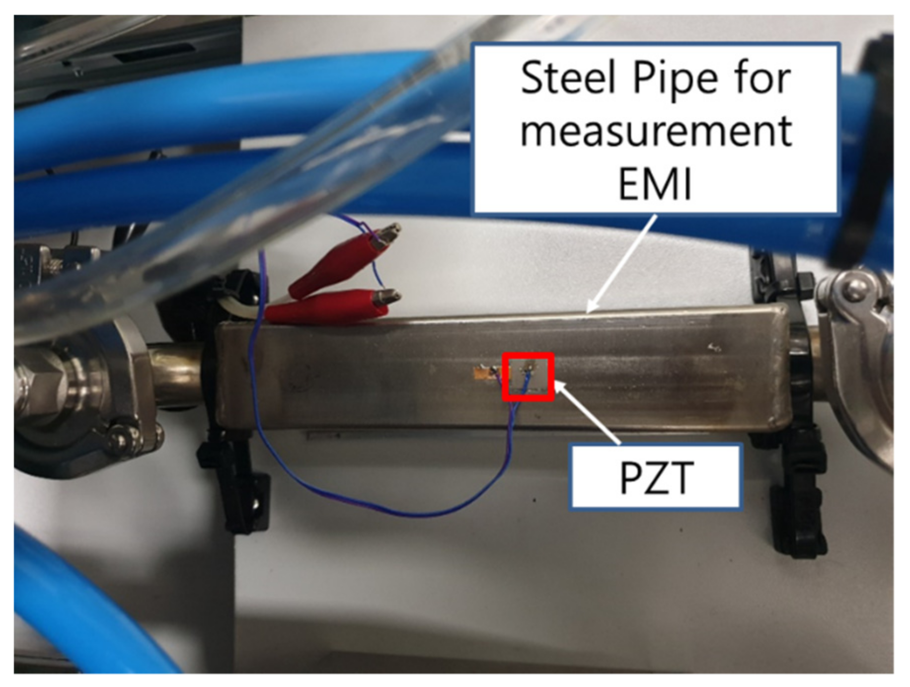
To overcome this limitation, this study proposed an EMI-based pressure measurement system using an external pipe line. The external pipe used to measure the EMI according to the pressure decay was connected to the air pipe line for the PDT of membrane modules. To improve the pressure sensitivity, the thickness of the pipe was 1.0 T (1.0 mm), and its design exhibited a rectangular parallelepiped shape for attaching the PZT patch to the pipe. The size of the external steel pipe was 30 × 30 × 100 mm3 and the 10 × 10 mm2 PZT patch was attached at the center of pipe, as shown in Figure 1.
3. Experimental Verification
3.1. Experimental Setup
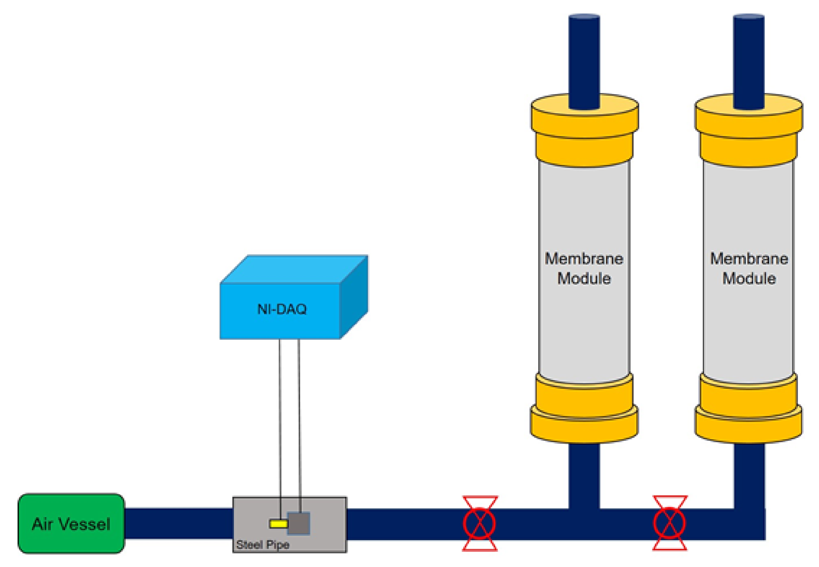
To verify the proposed method, pilot-scale tests were performed. The test specimen was a real-size membrane module consisting of two membranes, as shown in Figure 2. The PDT was performed on each membrane, and the air was inputted through an external steel pipe for measuring EMI. Air was introduced to replace water in the membrane with the calculated volume, after which the air injection was stopped. The EMI of the external steel pipe was measured every 8 s, and the actual pressure was measured using an electrical pressure gauge installed after the external pipe. The EMI signals were measured using the NI-DAQ system, which consists of an arbitrary waveform generator, a digitizer, and a controller.
In the first test (test 1), the pressure was maintained to describe the intact condition, which indicates an undamaged condition. In the second test (test 2), the pressure was maintained to be in a normal state until a complete air–water replacement was achieved; subsequently, the pressure was decreased by opening the air valve artificially to simulate membrane damage. The air valve connected to the membrane module was opened at the first stage to simulate membrane damage for the first time in tests 3 and 4.
3.2. Test Results
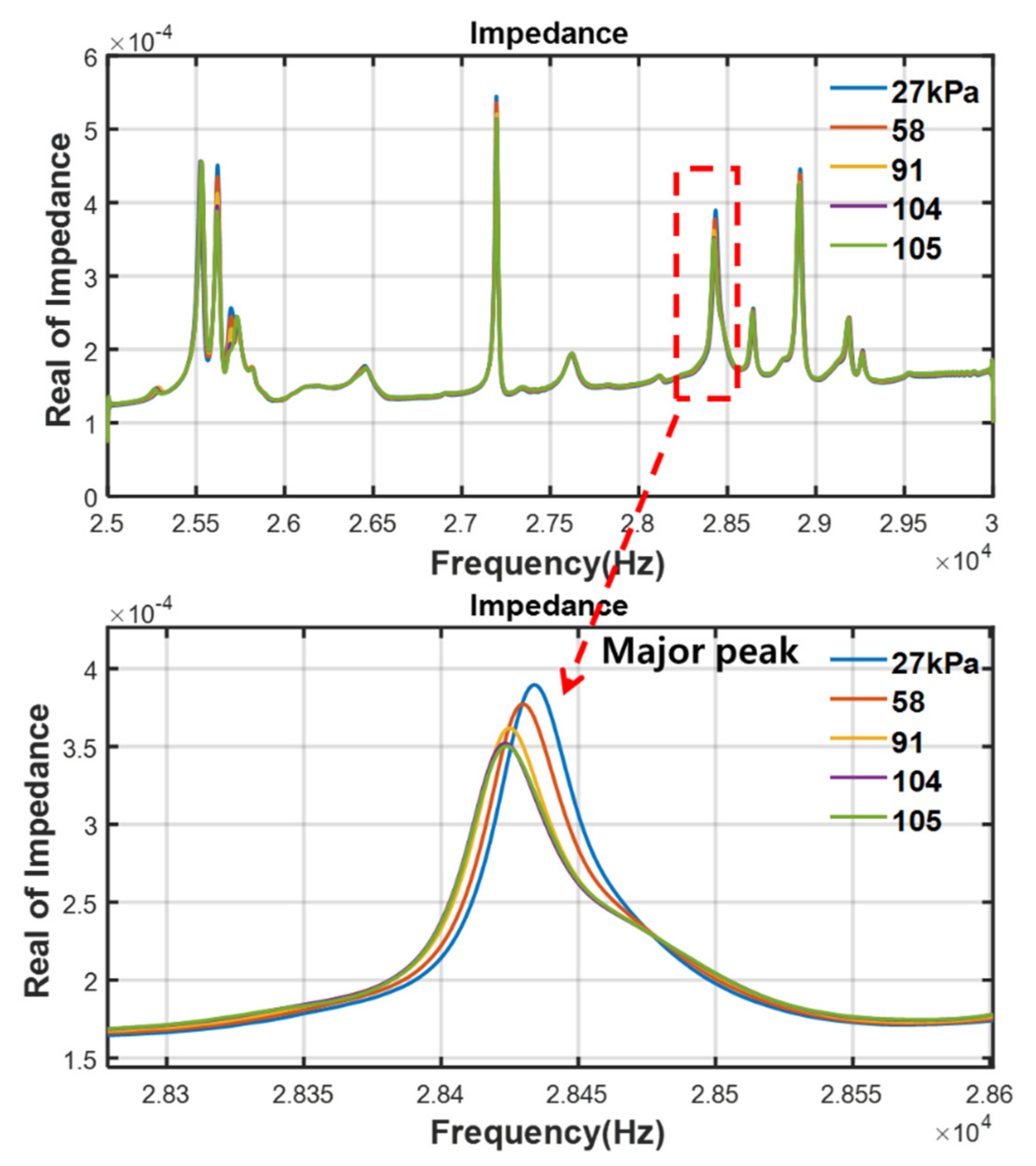
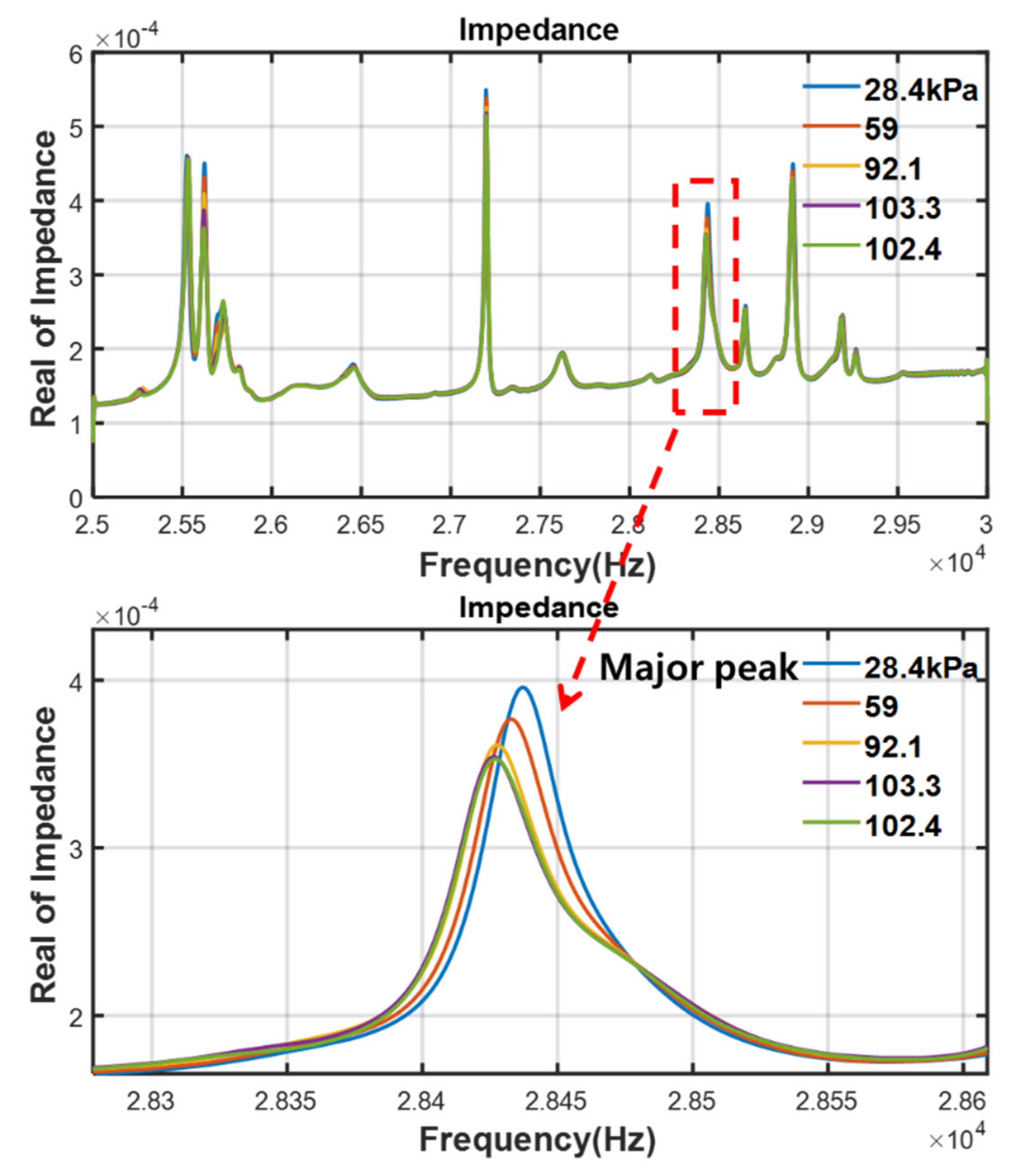
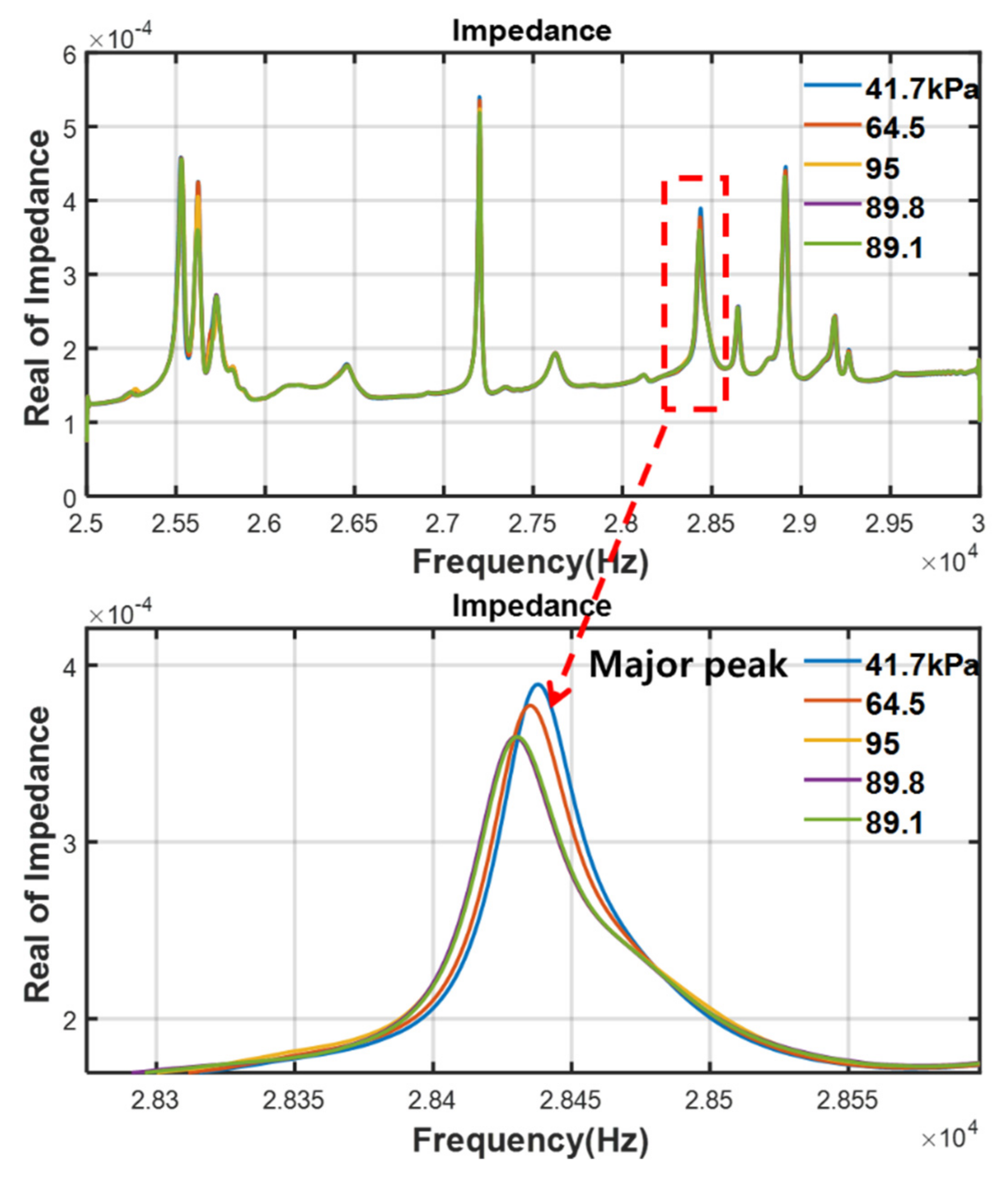
Figure 3, Figure 4, Figure 5 and Figure 6 show the measurement results of the EMI signals for different conditions with the air valve being open (tests 1 to 4). In the frequency range of 25 to 3 kHz, 11 resonance frequencies existed, and the amplitude of the resonant point decreased with an increase in pressure. To extract the index for pressure estimation, the major peak, which indicated the most sensitive resonant frequency according to the changes in pressure, was determined to be around 28.5 kHz.
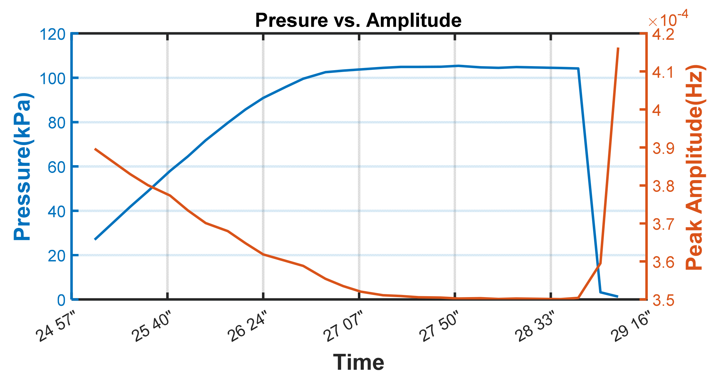
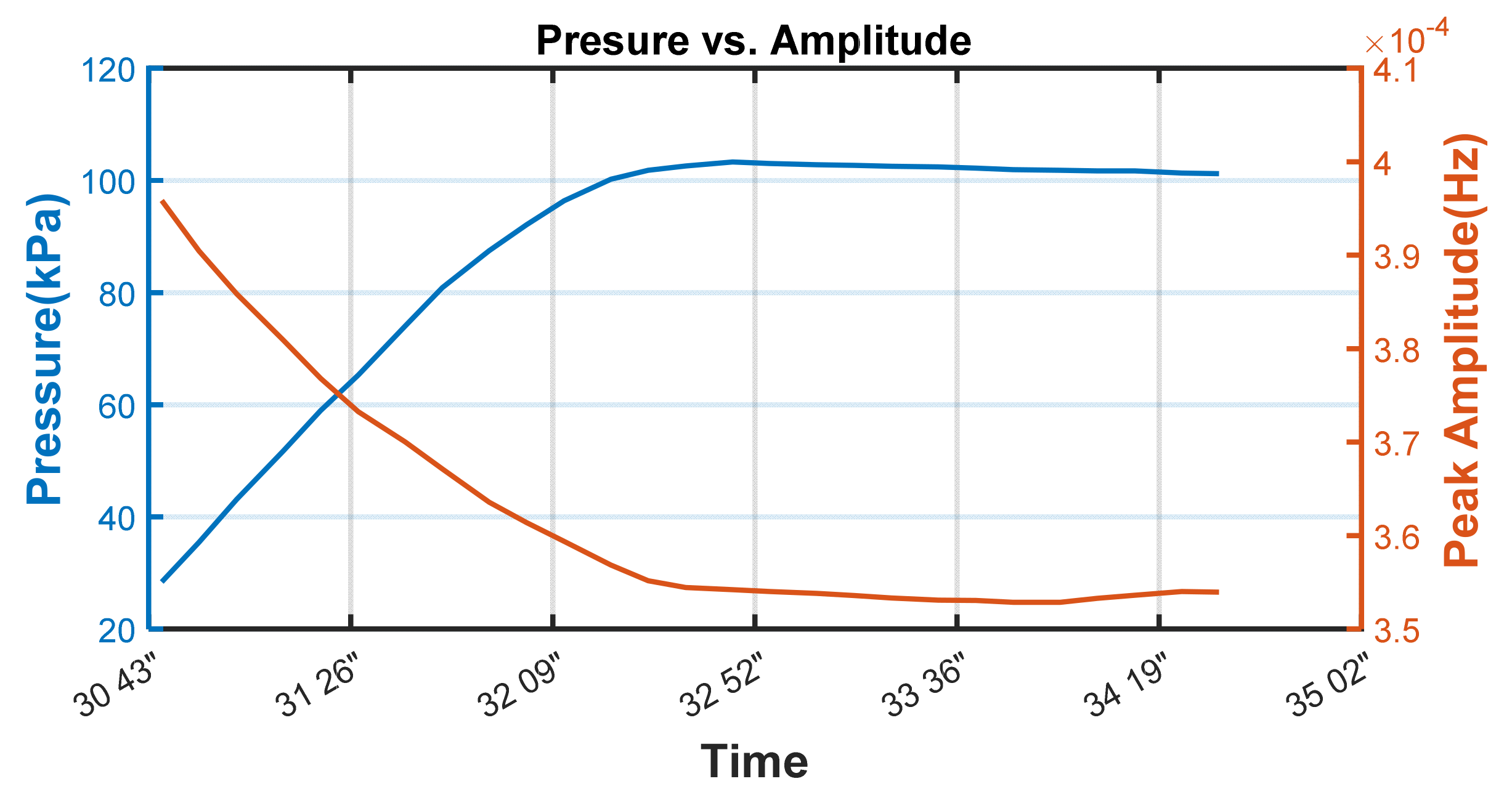
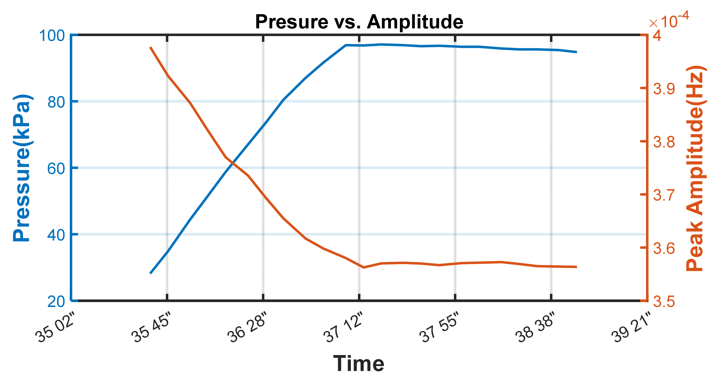
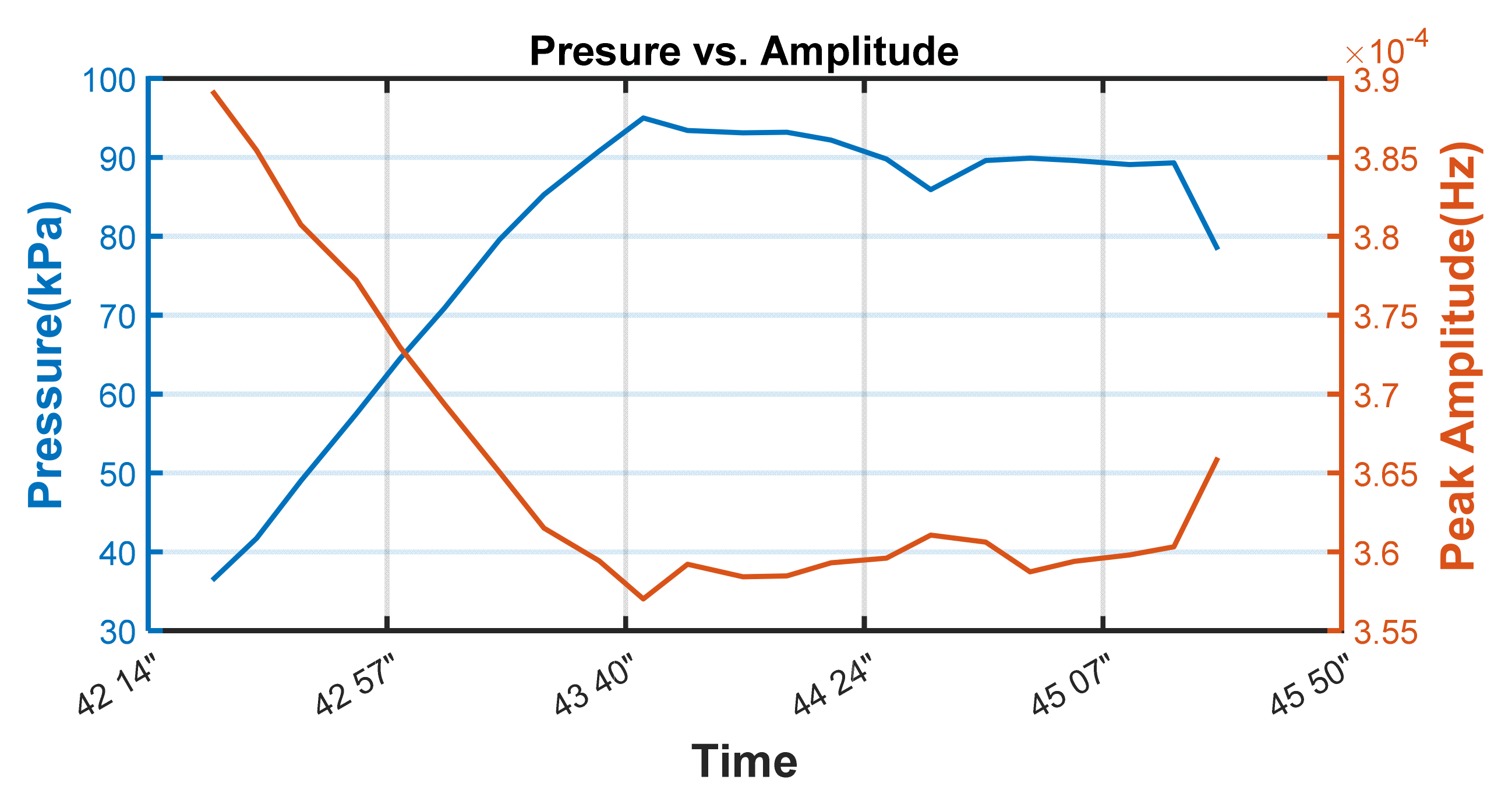
The amplitudes of the major peaks were extracted and compared with reference pressures, which were measured using a pressure sensor installed at the steel pipe, as shown in Figure 7, Figure 8, Figure 9 and Figure 10. The amplitude of the major peak was inversely proportional to the changes in the pressure in every test. This is because the damping ratio of the air-pressurized steel pipe is lower than that of the intact state. The amplitude of the major peak of the EMI signals is directly affected by the pressure inside the steel pipe, and it can be used as a pressure index for pressure estimation.
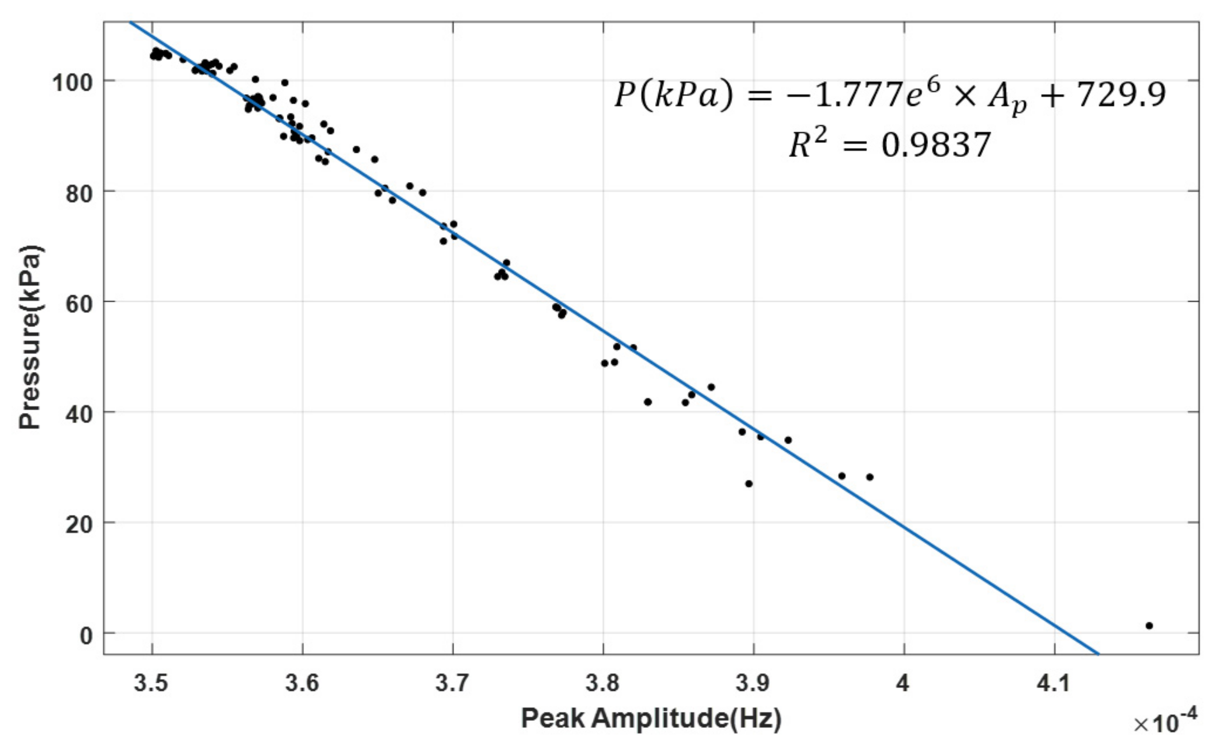
The linear regression method was used to determine the relationship between the amplitude of the major peak and the pressure inside the membrane, as shown in Figure 11. The amplitudes of the EMI signals were linearly matched with the pressure decay and expressed in Equation (2).
where P is the estimated pressure in kPa and Ap is the amplitude of the major peak of the EMI signal.
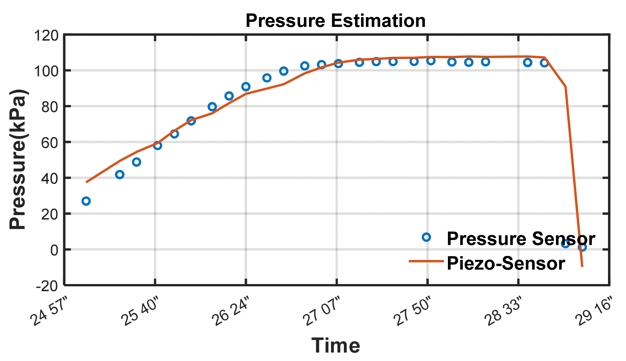
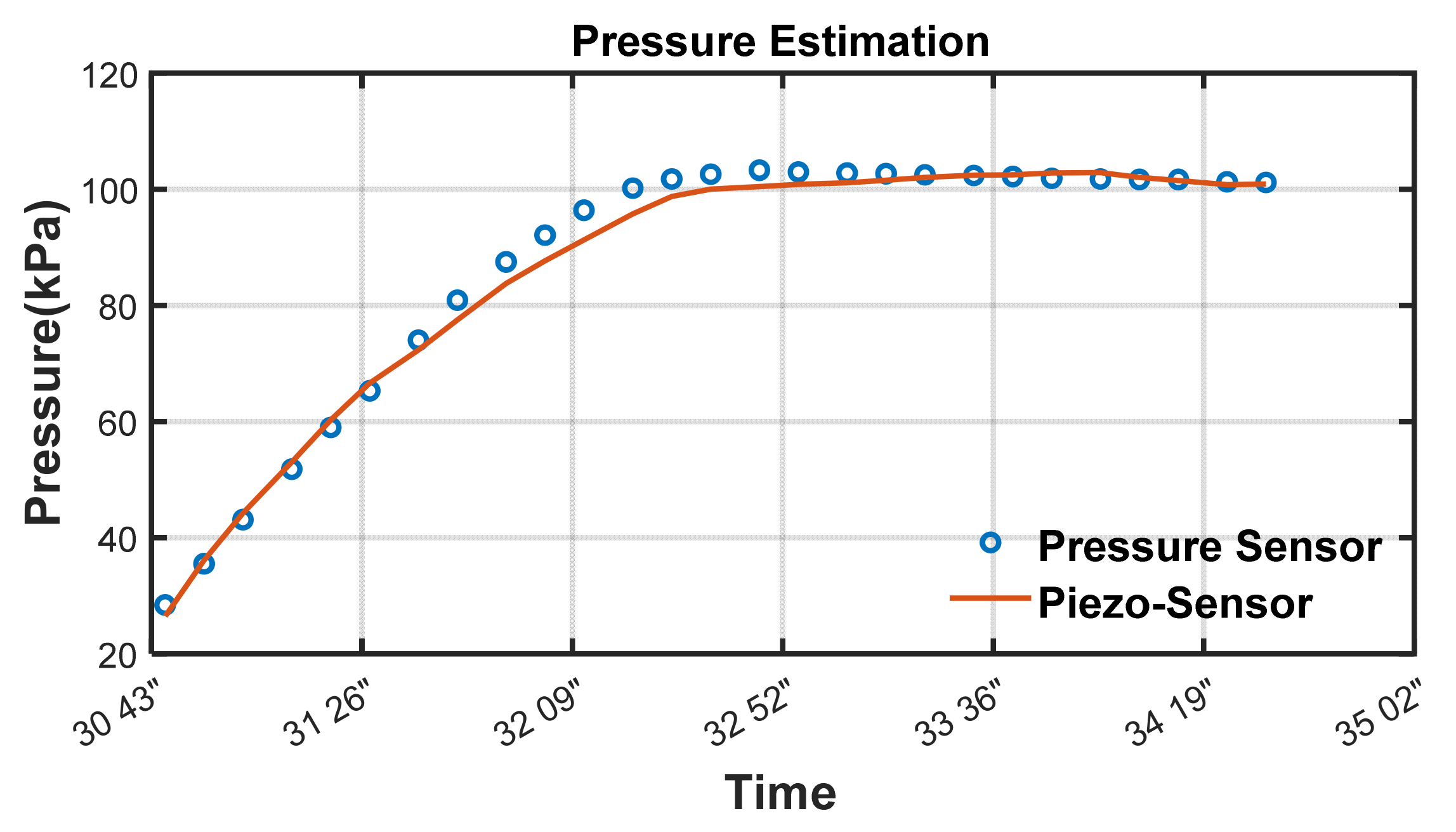
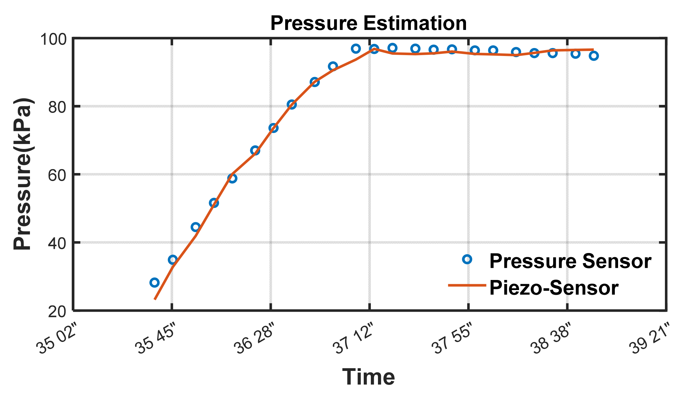
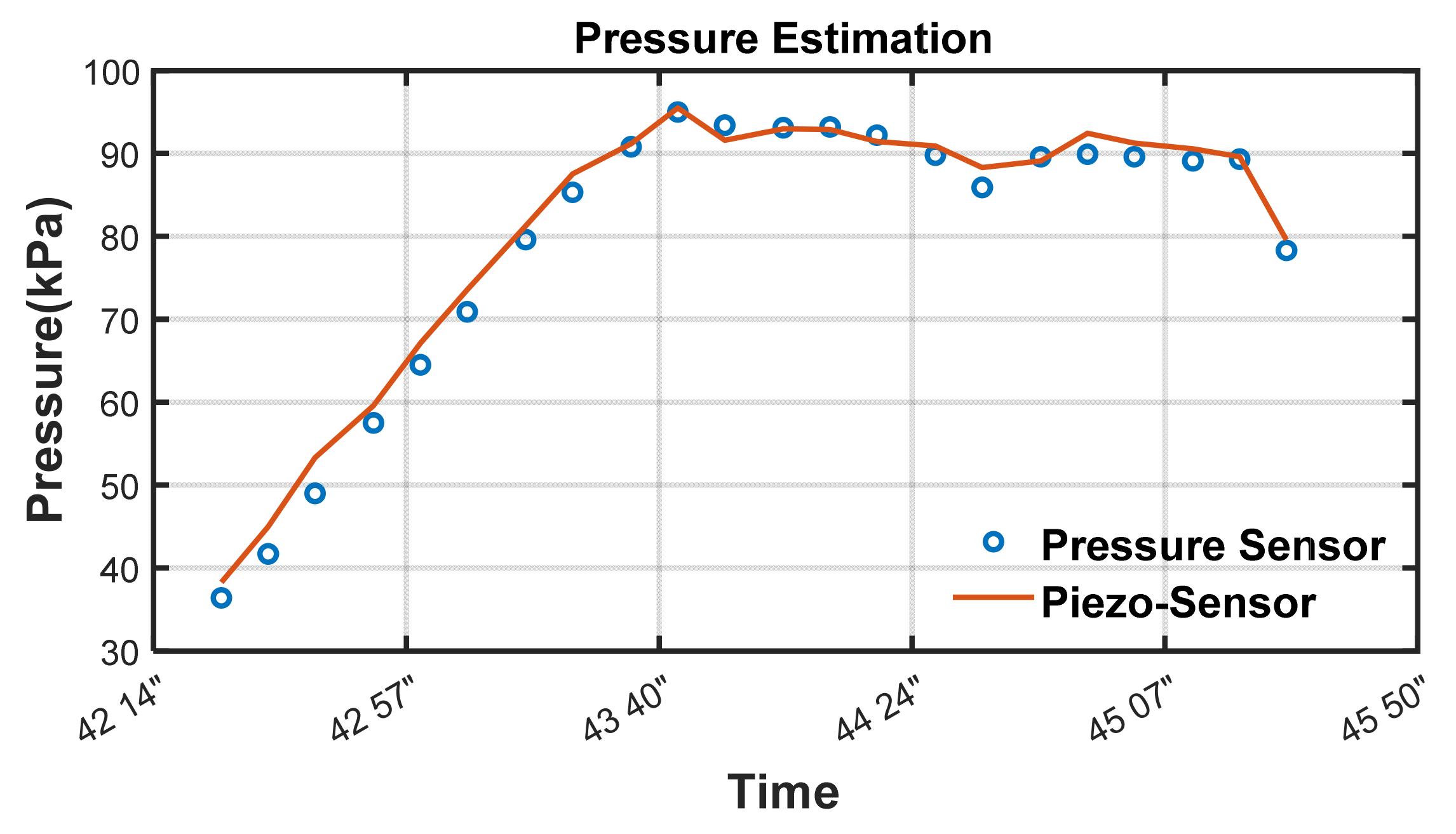
The estimated pressures calculated using the pressure estimation equation (Equation (2)) were compared with the reference pressure in Figure 12, Figure 13, Figure 14 and Figure 15. In test 1 (intact case), the estimated pressure was maintained at the maximum pressure for PDT. On the other hand, the estimated pressure dropped after reaching the maximum pressure (test 2) and during and after pressurization (tests 3 and 4) in tests 2 to 4 (damage simulated case). According to the results, the EMI-based pressure estimation method can estimate the actual pressure inside the air pipe, and it can be used to detect membrane damage during PDT more sensitively than conventional pressure sensors.
4. Conclusions
This study proposed a method for monitoring the operating conditions of a PZT-based membrane using EMI measurement in an external air pipe. The EMI signal changes according to the changes in the mechanical properties of the host structures. The amplitude of EMI signals can be attenuated by the high damping ratio of the host structure, such as polymers, which are mainly used for membrane casings. To improve the signal quantity, this study measures the EMI at the external air pipe and not at the membrane casing. Thus, the pressure decay caused by membrane damage during PDT can be measured more sensitively and quickly. Pilot-scale tests were performed to verify the performance of the proposed method. The PDT was performed using a PZT-attached air pipe, and the pressure was measured during PDT by using PZT; further, a pressure gauge was used to measure the reference pressure. The test was performed four times under different pressure conditions. The entire volume of the input air was the same for each test, but the output air valve was closed in test 1 to simulate an undamaged condition; subsequently, it was opened slowly in test 2 after the entire volume of air entered, and opened before the PDT in tests 3 and 4 to simulate the damaged condition. The EMI signals changed according to the variations in pressure inside the steel air pipe. To index the signal variation, the amplitude of the major peak was extracted and compared with the reference pressure. The amplitude of the major peak was inversely proportional to the pressure change. The pressure estimation equation was derived using linear regression between the amplitudes of the major peak and the reference pressures. The pressure can be estimated using the pressure estimation equation with measured EMI signals for the undamaged and damaged conditions. According to the results, the proposed method for monitoring the operating conditions of the PZT-based membrane, which uses the EMI of an external steel pipe, can be a solution to improve the sensitivity and speed of PDT. Furthermore, the proposed method can find the pressure drop before maximum pressure of PDT due to the high sensitivity of EMI, while the conventional PDT can detect the defect of membrane some minutes after gas–liquid substitution.
Author Contributions
Conceptualization, J.K. and Y.-S.L.; methodology, J.K.; validation, S.L. and H.-S.K.; writing—original draft preparation, J.K. and J.E.; writing—review and editing, S.L., Y.-S.L. and H.-S.K.; funding acquisition, J.K., J.E. and S.L. All authors have read and agreed to the published version of the manuscript.
Funding
This work was supported by the Korea Ministry of Environment as “Development of the big data platform and standardization techniques for the management of waterworks and sewer systems (2020002700001)” and a part of the project titled “Development of Disaster Control and Aging Management Method for Port Infrastructure (20210603)”, funded by the Ministry of Oceans and Fisheries, Korea.
Institutional Review Board Statement
Not applicable.
Informed Consent Statement
Not applicable.
Data Availability Statement
The data presented in this study are available on request from the corresponding authors.
Acknowledgments
This work was supported by the Korea Ministry of Environment as “Development of the big data platform and standardization techniques for the management of waterworks and sewer systems (2020002700001)” and a part of the project titled “Development of Disaster Control and Aging Management Method for Port Infrastructure (20210603)”, funded by the Ministry of Oceans and Fisheries, Korea.
Conflicts of Interest
The authors declare no conflict of interest.
References
- David, H.; Furukawa, P.E.; Ch, E. NWRI Final Project Report: A Global Perspective of Low Pressure Membranes; National Water Research Institute: Fountain Valley, CA, USA, 2008. [Google Scholar]
- Guo, H.; Wyart, Y.; Perot, J.; Nauleau, F.; Moulin, P. Low-pressure membrane integrity tests for drinking water treatment: A review. Water Res. 2010, 44, 41–57. [Google Scholar] [CrossRef] [PubMed]
- Laîne, J.M.; Glucina, K.; Chamant, M.; Simonie, P. Acoustic sensor: A novel technique for low pressure membrane. Desalination 1998, 119, 73–77. [Google Scholar] [CrossRef]
- Phillips, M.W.; DiLeo, A.J. A validatable porosimetric technique for verifying the integrity of virus-retentive membranes. Biologicals 1996, 24, 243–253. [Google Scholar] [CrossRef] [PubMed]
- Adham, S.S.; Jacangelo, J.G.; Laine, J.M. Low-pressure membranes: Assessing integrity. J. AWWA 1995, 3, 62–75. [Google Scholar] [CrossRef]
- Johnson, W.T. Automatic monitoring of membrane integrity in microfiltration systems. Desalination 1997, 113, 303–307. [Google Scholar] [CrossRef]
- Johnson, W.T. Predicting log removal performance of membrane systems using in-situ integrity testing. Filtr. Separat. 1998, 1, 26–29. [Google Scholar] [CrossRef]
- Randles, N. Large scale operating experience in membrane systems for water and waste water reclamation. Desalination 1997, 108, 205–211. [Google Scholar] [CrossRef]
- Panglisch, S.; Deinert, U.; Dautzenberg, W.; Kiepke, O.; Gimbel, R. Monitoring the integrity of capillary membranes by particle counters. Desalination 1998, 119, 65–72. [Google Scholar] [CrossRef]
- Banerjee, A.; Lambertson, M.; Lozier, J.; Colvin, C. Monitoring membrane integrity using high sensitivity laser turbidimetry. Water Sci. Technol. Water Suplly 2001, 1, 273–276. [Google Scholar] [CrossRef]
- Crozes, G.F.; Sethi, S.; Mi, B.; Curl, J.; Marinas, B. Improving membrane integrity monitoring indirect methods to reduce plant downtime and increase microbial removal credit. Desalination 2002, 149, 493–497. [Google Scholar] [CrossRef]
- Krantz, W.B.; Lin, C.S.; Sin, P.C.Y.; Yeo, A.; Fane, A.G. An integrity sensor for assessing the performance of low pressure membrane modules in the water industry. Desalination 2011, 283, 117–122. [Google Scholar] [CrossRef]
- Lee, Y.-S.; Kim, J.; Lee, C.; Park, S. Applicability investigation of piezoelectric sensor-based damage detection technique for membrane. Desalin. Water Treat. 2019, 143, 24–28. [Google Scholar] [CrossRef]
- Kim, J.; Lee, C.; Park, S. Artificial neural network-based early-age concrete strength monitoring using dynamic response signals. Sensors 2017, 17, 1319. [Google Scholar] [CrossRef] [PubMed] [Green Version]
- Lee, C.; Kim, J.; Park, S.; Kim, D.H. Advanced fatigue crack detection using nonlinear self-sensing impedance technique for automated NDE of metallic structures. Res. Nondestruct. Eval. 2015, 26, 107–121. [Google Scholar] [CrossRef]
- Park, S.; Inman, D.J.; Lee, J.J.; Yun, C.B. Piezoelectric sensor-based health monitoring of railroad track using a two-step support vector machine classifier. J. Infrastruct. Syst. 2008, 14, 80–88. [Google Scholar] [CrossRef]
- Bhalla, S.; Soh, C.K. Structural health monitoring by piezo-impedance transducers, I: Modeling. J. Aerospace Eng. 2004, 17, 154–165. [Google Scholar] [CrossRef]
- Giurgiutiu, V.; Rogers, C.A. Modeling of the electro-mechanical (E/M) impedance response of a damaged composite beam. In Proceedings of the ASME Winter Annual Meeting, ASME Aerospace and Materials Divisions, Adaptive Structures and Material Systems, ASME Aerospace Division, Nashville, TN, USA, 14–19 November 1999; Volume 59, pp. 39–46. [Google Scholar]
- Liang, C.; Sun, F.P.; Rogers, C.A. Electro-mechanical impedance modeling of active material systems. Smart Mater. Struct. 1996, 5, 171–186. [Google Scholar] [CrossRef]
Figure 1.
External steel pipe for measuring EMI.

Figure 2.
Scheme of test setup.

Figure 3.
Variations in EMI according to internal pressure (test 1).

Figure 4.
Variations in EMI according to internal pressure (test 2).

Figure 5.
Variations in EMI according to internal pressure (test 3).

Figure 6.
Variations in EMI according to internal pressure (test 4).

Figure 7.
Comparison between pressure and amplitude of the major peak (test 1).

Figure 8.
Comparison between pressure and amplitude of the major peak (test 2).

Figure 9.
Comparison between pressure and amplitude of the major peak (test 3).

Figure 10.
Comparison between pressure and amplitude of the major peak (test 4).

Figure 11.
Results of linear regression between pressure and amplitude of EMI.

Figure 12.
Result of pressure estimation using EMI in the non-damaged state (test 1).

Figure 13.
Result of pressure estimation using EMI in the damaged case (test 2).

Figure 14.
Result of pressure estimation using EMI in the damaged case (test 3).

Figure 15.
Result of pressure estimation using EMI in the damaged case (test 4).

Publisher’s Note: MDPI stays neutral with regard to jurisdictional claims in published maps and institutional affiliations. |
© 2021 by the authors. Licensee MDPI, Basel, Switzerland. This article is an open access article distributed under the terms and conditions of the Creative Commons Attribution (CC BY) license (https://creativecommons.org/licenses/by/4.0/).
Share and Cite
MDPI and ACS Style
Kim, J.; Eom, J.; Lee, S.; Lee, Y.-S.; Kim, H.-S. Monitoring of the Operating Membrane Condition Using PZT Based EMI of External Steel Pipe. Water 2021, 13, 3407. https://0-doi-org.brum.beds.ac.uk/10.3390/w13233407
AMA Style
Kim J, Eom J, Lee S, Lee Y-S, Kim H-S. Monitoring of the Operating Membrane Condition Using PZT Based EMI of External Steel Pipe. Water. 2021; 13(23):3407. https://0-doi-org.brum.beds.ac.uk/10.3390/w13233407
Chicago/Turabian StyleKim, Junkyeong, Jungyeol Eom, Sangyoup Lee, Yong-Soo Lee, and Hyung-Soo Kim. 2021. "Monitoring of the Operating Membrane Condition Using PZT Based EMI of External Steel Pipe" Water 13, no. 23: 3407. https://0-doi-org.brum.beds.ac.uk/10.3390/w13233407
Note that from the first issue of 2016, this journal uses article numbers instead of page numbers. See further details here.