Article

Combining Fish Passage and Sediment Bypassing: A Conceptual Solution for Increased Sustainability of Dams and Reservoirs

1
Department of Salmonid Fishes, Norwegian Institute for Nature Research (NINA), Høgskoleringen 9, 7034 Trondheim, Norway
2
Laboratory of Hydraulics, Hydrology and Glaciology (VAW), ETH Zurich, HIA C 57, Hoenggerbergring 26, CH-8093 Zurich, Switzerland
3
Department of Civil and Environmental Engineering, Norwegian University of Science and Technology (NTNU), S.P. Andersens veg 5, 7491 Trondheim, Norway
*
Author to whom correspondence should be addressed.
Submission received: 19 April 2022 / Revised: 8 June 2022 / Accepted: 16 June 2022 / Published: 20 June 2022
(This article belongs to the Special Issue Fish Passage at Hydropower Dams 2.0)

Abstract

:
Sedimentation is one of the main eco-morphological and technological challenges associated with reservoirs. Sedimentation not only reduces the functional capacity of a reservoir by filling it, but also changes downstream sediment dynamics and habitat availability for the aquatic biota. Additionally, dams hinder free bi-directional fish passage, emerging as a major threat to species of migratory fish. In the past decades, mitigation measures aimed at reducing such environmental and technological impacts have been developed. Sediment bypass tunnels (SBTs) have been shown to successfully help prevent reservoir sedimentation, whereas fish passages have been found to be potential solutions to facilitate bi-directional passage of fish. However, the construction of such structures, in particular of SBT, can be extremely costly. The development of design solutions that can function both for downstream sediment transport and up- and downstream fish passage should be considered as they can mitigate ecological deficiencies of reservoir operations while accounting for economic feasibility. Possibilities and challenges of combining SBT and fish passage were explored by bringing together a team of interdisciplinary specialists on hydraulics, sediment transport and continuity, bypassing, hydraulic structures, hydropower engineering, aquatic biology, and fish passage in a two-day workshop. Here, we present potential solutions identified during the workshop for integrating SBT and fish passage.

1. Introduction

Accumulation of sediments by dams is considered the main problem related to storage capacity and lifetime of reservoirs [1,2,3,4,5,6,7,8,9,10,11,12]. Additionally, accumulation of sediments also has strong negative impacts on downstream river eco-morphology and biodiversity [13,14,15,16,17,18,19].
It is estimated that about 1% of the world’s storage capacity in existing large reservoirs is lost per annum due to sedimentation, and that by 2050, 42% of the global storage capacity will be lost [20]. The global amount of sediment trapped in reservoirs has been estimated to be 4–5 Gt per year or 25–30% of the total sediment runoff in rivers [21], making reservoir sedimentation a threat to both energy production and water supply globally [21,22]. The downstream impacts of reduced sediment transport can be substantial by increasing downstream erosion in rivers [23], deltas [24], and coastal areas [25]. This reduced sediment transport can also cause structural problems for infrastructure, such as collapse of bridge piers and bank protection. Moreover, it can lead to severe ecological effects due to habitat degradation compromising biodiversity sustainability [5,9]. Effects of sedimentation in reservoirs can also extend upstream reservoirs by, e.g., increased flooding risk and establishment of new species [5,9].
Dams not only hinder sediment transport, but can also strongly impact fish populational sustainability by preventing free volitional bi-directional movement of fish [26]. Whereas for non-obligatory migratory fish this fragmentation mainly impacts accessibility of habitats [27,28], for obligatory migratory fish this can lead to total lack of access to critical habitats needed to complete their lifecycle, e.g., breeding areas. Obligatory migratory and endemic fish species are then especially vulnerable to extinction caused by the presence of dams in rivers [29,30]. Construction of fishways [31] is the main mitigation solution used for restoring river connectivity and mitigating negative impacts of dams on fish. A fishway should enable the movement and unrestrained access to free-flowing reaches above and below the obstacle. Moreover, fish should be able to find and enter the fishway without experiencing any delay; and entry should be immediately followed by successful upstream or downstream passage, with no energetic stress, disease, injury, predation, or other fitness-relevant costs associated with passage (i.e., the transparency fishways concept) [26,32]. From an operational perspective, fishways need to be cost-efficient in both construction, lifetime, and maintenance. Thus, a fishway design needs to be optimized with respect to both biological and operational ideals [26].
Research and development of fishways have mainly been focused on economically and culturally important fish species such as salmonids, leading to a lack of knowledge and information required for the development of engineered solutions for upstream migration of other fish species having different biomechanical skills and for downstream passage in general [33]. As a consequence, efficiency of fishways for species other than salmonids is commonly compromised [34]. Fishways can, in some instances, work as traps for fish, or selective agents, causing delays in migration, increasing exposure to predation and concomitant mortality, and select specific life stages or individual behavioral traits impacting fish populations [35,36,37,38].
Although there have been studies focusing on the development of downstream passage and guidance solutions for fish (e.g., louvers, bar-racks, bubble curtains [39,40]), successful downstream passage of fish still is a challenge to scientists, engineers, authorities, and hydropower plant (HPP) operators due to insufficient knowledge of behavioral and hydraulic requirements. Moreover, regarding upstream solutions, most of the existing technical solutions for downstream fish passage have been developed for salmonids. Additionally, they have been mainly developed for low-to-medium-head HPPs. As a consequence, both upstream and downstream fish passages at high-head HPPs and dams are mostly not considered.
To ensure sustainability of dams and reservoirs, the problems related to sediment connectivity and fish passage need be addressed and solved in a comprehensive way. In this paper we introduce the potential for multipurpose structures that aim at facilitating both sediment transport and fish migration. These structures were identified by an interdisciplinary group of experts during a two-day workshop held in Norway in February 2019.

2. Background: Sediment Bypass Tunnels and Fish Passage

In this section, we aim to summarize the main principals for and challenges associated with single-purpose SBT and fish passage structures, as an introduction to Section 3, in which we introduce possible solutions that combine both SBT and fish passage.

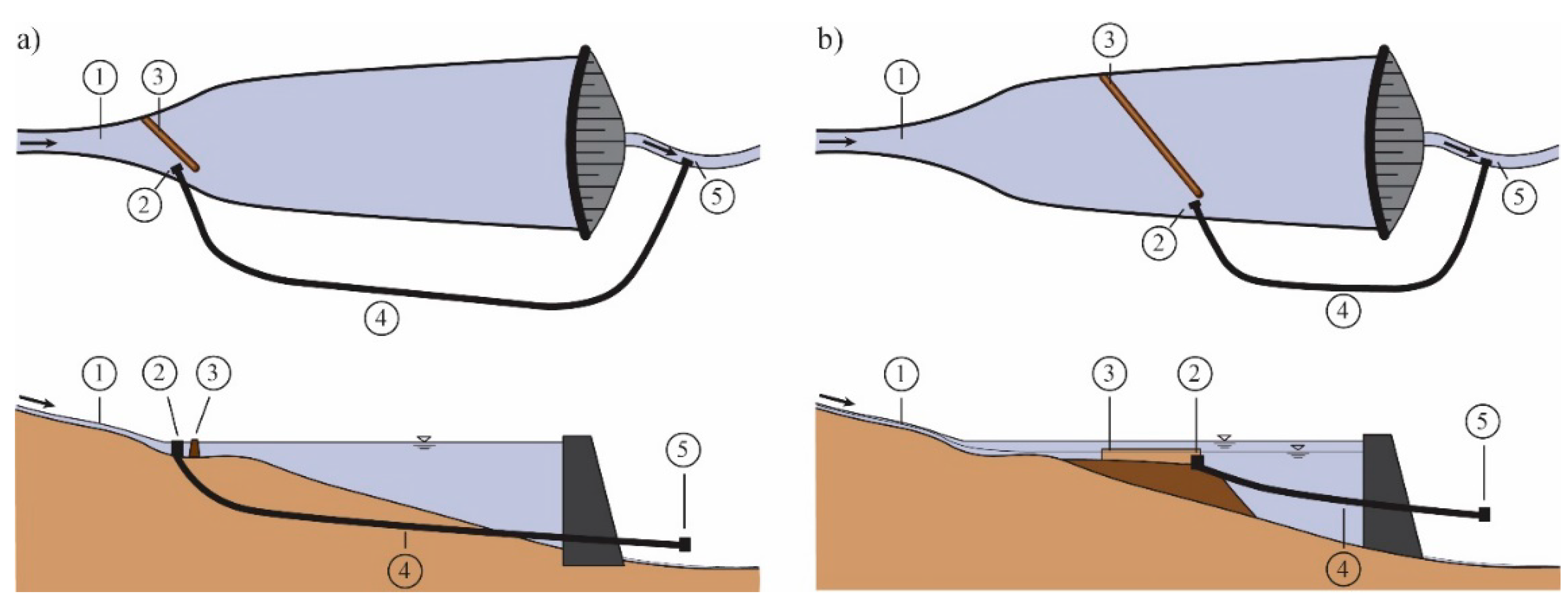
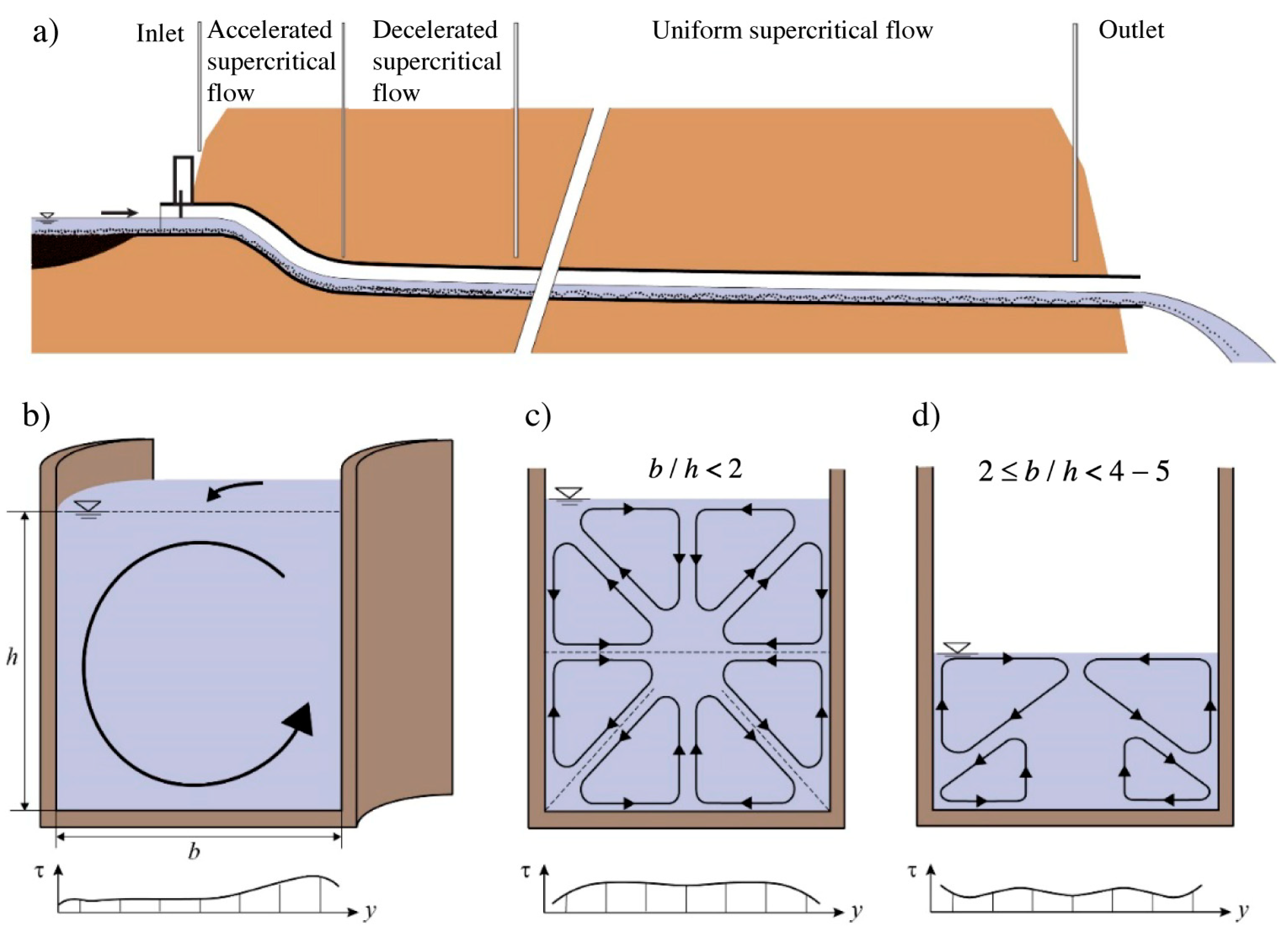
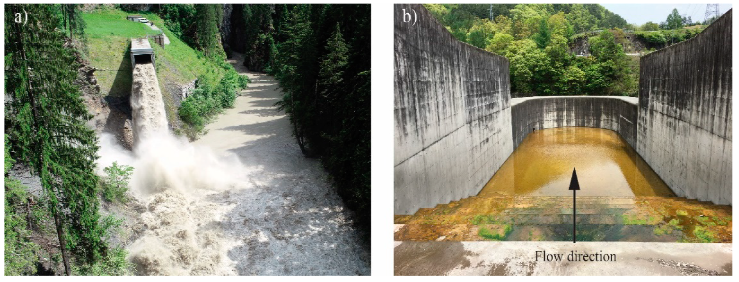
2.1. Sediment Bypass Tunnels

Reservoir sedimentation is a severe problem affecting reservoirs for multiple purposes such as electricity production, irrigation, water supply, and flood retention [12,41,42,43,44]. Sedimentation, and subsequent loss of reservoir volume, reduce operational life time and potentially also dam operational safety, resulting in financial losses [1,2,8,12,44]. Moreover, sediment trapping behind dams can also cause negative environmental effects such as river bed incision and eco-morphological impoverishment of downstream river reaches [2,15,17,18,19,22]. Several measures are available to counteract reservoir sedimentation [12,22,45,46]. Sediment bypassing has been shown to be an effective countermeasure to reduce sediment accumulation of both bed and suspended loads to levels similar to pre-dam conditions (Figure 1, [22,47,48,49]). Additionally, by establishing sediment continuity, sediment bypassing also improves both the quality and quantity of downstream river habitats [17,18,19,50].
In mountainous areas and narrow valleys, sediments are typically bypassed through tunnels, termed sediment bypass tunnels (SBTs), but bypass channels and waterways can also be used. An overview of global SBTs in operation, under construction or planned, in addition to the state-of-the-art SBT research, is given in Boes [51], Sumi [52], and Müller-Hagmann [48], and current design considerations are summarized by Boes et al. [53] and Hager et al. [12]. The general design of SBT includes a guiding structure, an intake, the tunnel itself, and an outlet structure (Figure 1, [9,48,54,55,56]). The guiding structure diverts sediment-laden inflows to the SBT intake, particularly bedload. From there, the water-sediment mixture is bypassed through the tunnel around the dam and released into the downstream river reach via the outlet structure. SBTs are classified into two different types depending on location of the inlet. Type A SBTs feature an inlet at the reservoir head with free-surface inflow (Figure 1a), whereas the inlet location of type B SBTs is located within the reservoir (Figure 1b). Type A SBTs mitigate sediment deposition, in particular of bedload particles, in the entire reservoir. However, SBTs of type A can be long, depending on the geometry and topography of the reservoir, and hence require a high investment cost, whereas type B SBTs are shorter and less costly. Although type B STBs in general are cheaper to construct, they can have higher operational cost, e.g., due to reservoir water level drawdown during bypassing, which needs to be considered when evaluating the total costs. Water level drawdown is used to create high shear stresses along the bottom of the reservoir stretch upstream of the intake to allow for continuous bedload transport from the head of the reservoir to the tunnel intake (Figure 1b). Hence, most of the existing SBTs (approximately 30 reported worldwide) are of type A.
Commonly the design discharge of existing SBTs varies between 38 and 1000 m3/s, corresponding to a flood discharge with a return period of typically a few years [9,48]. Most existing SBTs are installed at small- to medium-size reservoirs impounding up to a few million m3 [12,48]. Most SBTs have a steeply sloped acceleration section with a slope between 15% and 35% to achieve uniform supercritical flow, followed by a more mildly sloped section with a slope between 1% and 4% until the outlet structure (Figure 2a). The length of the existing SBTs ranges from 250 to 4300 m [53], with horseshoe or archway cross-sections. The dimensions and the design discharge of SBTs are commonly limited by technical and economic constraints.
SBT operation and geometry and concomitant hydraulic conditions emerge as the main features to be appraised when considering the potentiality of using SBTs to function as fish passage structures. Commonly, in SBTs, the ranges of Froude numbers and mean outflow velocities are 1.4 ≤ F ≤ 3 and 5.5 m/s ≤ Uout ≤ 17 m/s, respectively, with maximum flow velocities of about 20 m/s. By changing with the geometry of the SBT, these hydraulic characteristics differ among types of SBT. In submerged intakes (e.g., sediment venting tunnels in Taiwan, [57]), in which most of the sediment bypassing encompasses the passage of fine sediments, design flow velocities commonly vary between 20 and 30 m/s [53]. In addition to these high flow velocities, Prandtl’s first and second types of secondary currents frequently occur depending on the tunnel layout and operational conditions (Figure 2b–d; [58]). Prandtl’s first type of secondary currents occurs in tunnel bends with a spiral flow induced by centripetal forces [59]. As a result, the bed shear stress is higher at the inner side of the bend where high sediment transport occurs. Prandtl’s second type of secondary currents are developed in straight and non-circular open channel flows when the tunnel width (b) to flow depth (h) aspect ratio is below b/h < 4–5 (Figure 2c,d). This is the result of the presence of non-homogeneity and anisotropy of turbulence in the tunnel. These secondary currents superimpose the primary flow influencing mean flow velocities, turbulence intensities, and Reynolds and bed shear stresses [59,60,61,62]. In conditions where b/h < ~2, eight secondary cells develop and cause bed shear stress undulation (Figure 2c). Bed shear stresses are lowest near the tunnel walls, reach maxima, and then flatten towards the tunnel center (Figure 2c, [62]). For ratios 2 ≤ b/h < 4 to 5, four secondary cells have been found to develop [61], resulting in high bed shear stresses near the tunnel walls. Demiral et al. [62] and Auel et al. [61] indicated that b/h ≈ 2 is critical, determining the number of secondary cells created, and their bed shear stress distributions. Bed shear stress plays a critical role in sediment transport, with higher values leading to higher bedload transport (detailed information can be found in Müller-Hagmann [48]). Prandtl’s secondary currents are commonly observed in Swiss, Japanese, and Taiwanese SBTs with aspect ratios 0.57 ≤ b/h < 2.2 [48]. Due to their characteristics, Prandtl’s secondary currents strongly determine sediment transport distributions and turbulence flow characteristics in a tunnel or channel. High transport rates of bedload particles in combination with high flow velocities may cause severe abrasion in SBTs and, hence, modify the invert roughness and hydraulics of SBTs. The annual SBT maintenance cost may amount to 1% of its investment cost [63]. As a consequence, depending on the aspect ratio and tunnel layout, the following may occur: (i) incision channels near the tunnel walls (in straight sections with 2 ≤ b/h < 4 to 5, [61,64]; (ii) a deep incision channel at the center of the straight SBT section (in straight sections with b/h < ~2, [62,64]; or (iii) incision channels along the inner wall of SBT bends [48,65].
High velocities, complex Prandtl secondary currents of first and second type, high turbulence, incision channels, and irregular invert abrasion patterns are expected to negatively affect fish movement if an SBT is used for fish passage. These are then key characteristics to be considered when trying to adapt SBT to function at the same time as fish passage structures.
Although the characteristics of the tunnel itself will determine the potential use of an SBT for fish passage, the characteristics of both the inlet and outlet structure of an SBT are equally important. SBT outlet structures are, in some cases, designed with a drop into a plunge pool to dissipate the high kinetic energy of the supercritical tunnel flow and to avoid backwater effects from sediment aggradation at the outlet (Figure 3a). In other instances, a stilling basin downstream of the SBT outlet can be used as an energy dissipator (Figure 3b). When considering adapting SBTs for functioning as fish passage structures, the characteristics of SBT outlets play a crucial role. The drop height, the outflow velocity, the stilling basin design, and the pool depth in the SBT outlet need to be compatible with the biomechanical characteristics of the target species to allow for a safe return of fish from an SBT to the river.

2.2. Fish Passage

When considering fish passage, it is imperative to understand fish swimming capacity and behavior, and the interactions of fish with the hydrodynamics of the flow. The design and choice of the type of fishway to be implemented and concomitant success of passage strongly depend on the integration of the former characteristics when developing the fishway.

2.2.1. Fish Swimming and Hydrodynamics

Fish species have different ecological requirements determining their spatial and temporal distribution. Fish movement, behavior, and adaptation to different niches is regulated by their biological functions (reproduction, feeding, motivation, physiological condition, etc.) which are strongly dependent on the characteristics of the aquatic habitats (hydraulics, temperature, substrate, oxygen levels, etc.) [66]. This dependence is mostly marked in migratory fish, for which moving between habitats is crucial to complete their biological functions. Longitudinal and lateral connectivity in rivers is then critical for fish population survival.
Fish swimming behavior and performance result from a complex decision process ultimately linked to fitness costs and gains of different swimming strategies [67]. Fish swimming is strongly affected by fluid motion [68] and by endogenous factors [69,70]. Fish can perceive heterogeneity of the flow in rivers through their hydrodynamic sensory system (lateral line, [71]) and use such cues as drivers of their behavior [72,73,74]. The functional components of the lateral line (the superficial neuromast and the canal neuromast) permit fish to discriminate both frequency and amplitude of a constant frequency wave stimulus, in addition to abrupt frequency changes from the mean flow [71]. Fish can thus determine flow direction and flow velocity, and use these as a source of information for navigation [71].
The easily quantifiable swimming speed is commonly used as an indicator of swimming performance, which varies among species. Fish species differ in their morphometric characteristics, and also in their biomechanics and ecological requirements. Morphometrics of the species and concomitant intraspecific morphometric variations associated with different life stages are strongly connected to fish biomechanics. In tandem with fish physiology, these determine fish swimming performance, which is commonly categorized as sustained, prolonged, and burst swimming speeds [75]. Sustained swimming speeds are those speeds that fish can maintain for long periods (>200 min) without muscular fatigue. Prolonged swimming speeds are those speeds that fish can maintain for 20 s to 200 min, and ends in fatigue. A sub-category within prolonged performance is the critical swimming speed, which is the maximum velocity that can be maintained by a fish for several hours, typically 200 min without fatigue. Burst swimming speed is the highest speeds attainable by fish and can be maintained for only less than 20 s. This speed is usually used by fish to pass through short high-velocity areas, such as the inlet or outlet of fish passages. Since swimming at prolonged speeds can be maintained for relatively extended periods and appears to not impose undue physical stress on the fish, many regulatory agencies’ guidelines recommend using prolonged swim speeds (in particular critical swimming speed) to define the maximum flow speed in a fish passage, beyond which the efficiency of such structures for the target species is expected to be compromised.
Fish swimming speed and behavior are significantly affected by flow velocity, acceleration, and turbulence (eddy size, Reynolds shear stress) [33,68,73,76,77], which are therefore considered as determining factors for the development of fish-friendly structures. Fish migration is a complex and energetically demanding phenomenon, in which associated high levels of energy expenditure can compromise an individual’s fitness. As such, fish are known to adapt several swimming strategies and speeds [67] to reduce energetic cost associated with their swimming. During their migratory journey, fish avoid areas of high velocities that exceed their critical sustained swimming speed. This is a common behavior of fish species under both anthropogenic (e.g., at manmade structures) and natural conditions [33,77]. Silva et al. [77] found that the Iberian barbel (Barbus bocagei) avoids areas of velocities higher than 0.40 m/s when moving upstream in a fishway. In their analysis of Atlantic salmon (Salmo salar) smolts’ behavior in the river Mandal, Norway, Silva et al. [33] found that this species exhibited higher control of their swimming capacity in areas with velocity lower than their sustained swimming capacity (of 0.38 m/s). Flow velocities through fishways should then be evaluated to ensure that they do not exceed the acceptable velocity levels for the targeted species and that they do not cause energetic depletion during fish migration. Such levels differ among and within fish species, with the latter depending on fish life stage and fish length.
Fish swimming behavior is also affected by flow acceleration. Acceleration has been shown to play a twofold role in fish behavior depending on the fish species. Some fish species change their rheotaxis (i.e., orientation to the water flow direction) when approaching levels of higher acceleration (e.g., salmon smolts) [78,79], whereas others are attracted by similar conditions.
One of the most important hydraulic variables affecting fish behavior and swimming performance is turbulence, in particular, turbulence intensity, kinetic energy strain, eddy length scale, orientation, and vorticity [73,77,80,81]. Turbulent kinetic energy, which corresponds to the kinetic energy associated with fluctuating velocity at a given point [82], was shown to affect fish swimming performance [73,83] by increasing energetic costs of swimming [84]. Enders et al. [84], who focused on developing a swimming cost model for juvenile Atlantic salmon by estimating the total costs of swimming in a respirometer, found that total swimming costs increased with the increment of turbulent kinetic energy. Turbulent eddies, coherent rotating structures in the flowing fluid often described by their diameter, orientation, and rate of rotation or vorticity, have been considered as primary variables, affecting fish orientation, stability, and swimming speed [81]. Eddies seem to play a twofold role in fish swimming capacity and performance. Fish can use the energy associated with small eddies (smaller than ⅔ of fish total length) to move forward, whereas, when facing big eddies (bigger than ⅔ of fish total length), fish can experience disorientation and loss of balance and stability, which will imply higher energetic requirements for re-establishing balance and orientation [76,77,83,85]. Reynolds shear stress has also been shown to strongly affect fish swimming performance and stability [73,83], and at extremely high levels (≥700 N/m2) it may cause severe injury or even mortality [83,85]. Ultimately, fish swimming is also limited by energy dissipation. High levels of energy dissipation can hamper fish swimming capacity. Energy dissipation of up to 200 W/m3 is generally taken as the upper limit for volumetric power in fishways for salmonid species, whereas levels lower than 150 W/m3 are considered to be suitable for other riverine species such as cyprinids [86].
Fish behavioral response to different hydraulic structures does not only depend on fish biomechanics and the individual morphometric characteristics of each species, but also varies according to life stage, physiological conditions, energetic levels, motivational aspects, and prior learning processes, in addition to the direction of fish movement (up- or downstream). Thus, when designing a fishway, it is imperative to define the target species and life stage, and to consider the direction of the migration of the target specimens. Fish biomechanics and behavioral response to hydrodynamic restrictions should then underpin geometric design criteria of fishways, as variations in hydrodynamics, which depend on the fishway slope, flow discharge, and geometry of the fishway (drop between pools, number and length of the pools, cross-sections, dimensions of the orifices, etc.), will govern fish passage efficiency [73,77,78,87].

2.2.2. Fishways

During their lifespan, fish may travel considerable distances between distinct habitats [66]. Anthropogenic barriers commonly hamper such migration routes, which may strongly affect fish populations and even the persistence of a species [88]. Fishways, which aim to re-establish river connectivity and allow for free volitional migratory movement of fish [26,89], have been considered as good mitigation measures for some species. Fishways date back at least several centuries [90] but improvement is still needed, and advances are moving towards optimizing the efficiency of passage of different fishways for diverse species and fish life stages. Currently, a fishway needs to provide more than just fish passage. Fishways should be rendered to the concept of “transparency” [91] in terms of the effects on target species of fish approaching and passing the facility, and in terms of negligible fitness costs. Delay, injury, and damage levels and mortality need to be assessed and considered as a part of the evaluation of the efficiency of a fishway.
Depending on their design, fishways are commonly classified as: (1) technical structures (pool-type, vertical-slot and Denil fishways, surface-collector bypasses), (2) nature-like structures (nature-like bypass channels and fish ramps), and (3) special purpose structures (eel ladders, fish locks, and fish lifts) [92].
  • Technical fish passages: These are the most common fish passages. Technical fish passages aim to disperse the hydraulic head from the headwater to the tailwater using a channel divided into a succession of pools by several cross-walls. Such pools also allow for the dissipation of the energy to levels suitable for fish navigation. Flow discharge between pools occurs through submerged orifices or vertical slots (single or multiple) (e.g., pool-and-weir passes, vertical-slot passes, Denil passes) [92].
  • Nature-like fish passages: This type of fish passage aims to imitate as closely as possible the natural river conditions. These structures are characterized by dispersing the hydraulic head over a certain distance by keeping the slope as smooth as possible. The construction material usually corresponds to the one present in the river under natural conditions (e.g., bottom ramps, bypass channels, fish ramps) [93] (Haro et al., 2008).
  • Special fish passages: Special fish passage are specific structures designed for particular cases, such as fish lifts, fish locks, and eel ladders. Special fish passages are very selective and are not sufficient for mitigation of several fish species. This is the case of eel ladders that are designed to allow eels’ upstream migration. Similarly, fish lifts have been shown to be very selective structures as they have some restriction of functionality for small fish species, although successful applications exist [94,95,96] (Meyer et al., 2016, Coe, 2016, Schletterer et al., 2017).
In the past decades, research on the design of fishways has moved from a predominantly engineering approach, to a multidisciplinary approach in which geometries are determined based on the interaction between fish and hydrodynamics of the flow [26]. As such, the choice of which type of fishway to implement is currently both species-specific, as it depends on the ecological and biomechanical requirements of the target species, and site-specific, as it is subject to the characteristics of the system. Selection of a fishway should also rely on the premise of integrating a fishway as well as possible into the landscape, although the correct functionality of the fishway should always take priority over the landscaping [92].
Upstream fish passage science and technology is currently well studied, but downstream migration still poses challenges to scientists, engineers, authorities, and HPP operators due to insufficient knowledge about the behavior of different species under various hydraulic conditions at HPPs and dams, and the lack of design standards for passage technologies. As such, the new approach of using upstream fishway structures to facilitate downstream passage is augmenting, and research is making early advances towards that direction. Development of a multipurpose approach based on river structures (fishways, sediment bypass tunnel or channel) to facilitate two-way migration of fish can benefit by combining existing knowledge on the functionality of the structure and scientific knowledge on fish migration. This may also help lower the construction and associated maintenance costs.

3. Combined Structures for Fish Passage and Sediment Bypass Tunnels

Most of the SBTs are used for flushing sediment. Only a few these do so for up to around 100 days per year, which, combined with the high cost of construction, indicates the significant potential benefit of using these structures for other purposes during the remaining time.
Existing SBTs range in length from 258 to 4300 m, have low gradients ranging from 1% to 4% [9], and are mainly used in small and medium-sized reservoirs. Some are designed to bypass river bedload, whereas others bypass already settled suspended sediment and/or divert water flow with high suspended sediment concentrations. Depending on their intended function and topographic restrictions, SBTs have different design properties that can emerge as potential challenges for combined use for fish passage (e.g., intake configuration and placement; Figure 1).
When assessing the possibility of combining fish passage with SBTs, several aspects need to be considered to find the best solution to be implemented. This will strongly depend on both the target fish species and site-specific characteristics. Selection of the type of fish passage solution to be used in an SBT can be limited by external factors such as the amount of effort and funding that operators are willing to invest. The chance of successfully implementing a fish passage solution in a SBT will likely be higher if considered at an early stage of planning and before construction than if added to an existing SBT.
Safe passage of fish through an SBT cannot be achieved during sediment flushing, as flow conditions for sediment bypassing and for fish passage are very different. As described in the previous sections, the flow velocity and discharge during sediment bypassing are high, whereas, for fish passage, especially upstream passage, the velocities and turbulences need to be lower in accordance with the needs of the respective species (Section 2.2.1). This clear difference in operational requirements for either successful sediment transport or fish migration means that these must be separated in time or space.
Moreover, fish requirements regarding the hydrodynamics of the flow differs among species and within species, depending on their life stage and type of migration. Swimming performance is the result of a cost-efficient strategy adopted by fish to increase their survival, and performance will depend on whether fish are moving up- or downstream. Such biological constraints need to be explored within the limits set by the SBT structures to assess the feasibility for successfully integrating fish passage in SBTs. In the following sections, we present potential solutions, with their advantages and disadvantages, for fish passage in SBTs for both downstream and upstream movement of fish.

3.1. Downstream Fish Passage in SBT

If an SBT is to be used for safe downstream passage of fish, the hydrodynamics of the flow in the inlet, tunnel, and outlet of both the fish passage and the SBT need to be suitable for the entrance, passage, and exit of fish and sediments, respectively. Herein, we consider free-surface flow SBTs only. When considering downstream migration, the following technical aspects need to be considered:

3.1.1. Inlet Structures

Downstream passage of fish past hydropower plants is generally focused on guiding fish away from the turbine intakes, which is often done using physical or mechanical-behavioral structures (e.g., racks or screens) to divert fish towards a spillway or other bypass structures [40,97,98,99,100,101]. Guiding systems based on fish behavior and hydrodynamic conditions (Section 2.2) can also be used to help fish choose the desired passage. This is mainly achieved by changing the hydraulic conditions to levels suitable for fish navigation [79].
With the former in mind, due to their characteristics (intake located at the reservoir head with a guiding structure and river flow directly guided towards the bypass inlet without entering the reservoir), Type A SBTs (Figure 1a) are likely to be more suitable for modifications and construction of fish guiding and passage structures than Type B SBTs (Figure 1b). Moreover, Type A SBTs, by avoiding inlet structures in the vicinity of the dams, are also more likely to increase fish guidance efficiency and reduce migratory delays and predation risk [102,103,104,105], a key aspect when considering the development of fish passage solutions, as predation in reservoirs has been shown to be substantial and a strong ecological threat for some migrating fish [105,106].
Fish guidance efficiency to the entrance of the fish passage in the SBT is critical, as the number of fish entering the structure (rate of entry) will be the only measure of success of the structure’s ability to facilitate downstream passage of fish. Guidance efficiency at the inlet may be compromised by the radial or vertical lift gates installed in most SBT intakes. Such gates open from the bottom and create high velocity jet flows and high spatial velocity gradients at the inlet that can elicit avoidance responses from the fish. Thus, these types of gates can emerge as a potential obstacle for fish entrance into the fish passage structure, in particular, for fishes that migrate downstream close to the surface. This can be avoided by modifications of the intake gate or installation of new intake structures, (e.g., construction of a surface gate that releases enough water from the surface combined with sufficient water depth as a “cushion” in the gate’s tailwater, depending on the targeted species).

3.1.2. Downstream Passage through Tunnel

Herein, we explore four different variants for designing or redesigning a SBT to facilitate fish passage through the tunnel (see Table 1). The configurations are discussed below with different advantages and disadvantages with respect to the safe passage of fish, and for the general operation as SBTs. As the cross sections of STB tunnels are generally wide (2.9–7.8 m, [9]) and flow is supercritical, large discharges are required to attain water depths needed for safe passage of fish, and we therefore also consider configurations that separate fish passage from the main tunnel.
Variant 1 (V1): Pipe attached to SBT ceiling for fish passage:
This variant comprises a pipe installed to the ceiling of the SBT. This separates the fish passage from the sediment bypass, removing the risk of fish injuries resulting from the contact with the walls or the floor in the SBT. Moreover, the pipe itself is not affected by possible abrasions occurring during sediment flushing, which reduces the risks of damage to the construction. The discharge in the pipe can be adapted to the needs of safe transport of the fish downstream and will be substantially lower than what would be needed to provide a sufficient discharge in the SBT. Depending on the design of the inlet and outlet structure, this solution can also allow parallel operation of fish passage and sediment bypassing, due to the complete separation of both systems. Furthermore, it allows inspections, repairs, etc., in the SBT without affecting the use of the pipe for fish migration.
Nonetheless, this configuration can have disadvantages related to design and constructional aspects. Installation of a long pipe in the ceiling can be challenging with regard to its cost and difficulty in manually inspecting and maintaining. Further, as SBTs must be operated in conditions with free-surface flow, an installation of a pipe in the ceiling can lead to pressurization of flow (choking) if the cross-section for the free circulation of air above the water flow is insufficient. The installation of a pipe thus requires sufficient space for the water flow and a safety margin of non-usable area to ensure free-surface flow. If the diameter of the pipe in relation to the height of the tunnel necessitates a reduction in the water level during SBT operation, this may affect the SBT capacity and reduce its bypass efficiency.
Overall, this variant may allow the use of existing SBTs for downstream fish passage with relatively minor retrofitting, and the effort may be further reduced if included in the planning of new SBTs.
Variant 2 (V2) Depression in SBT floor:
This variant involves creating a small channel on the bottom of the SBT that can be used by fish for downstream passage (Table 1 V2). This configuration is quite promising in terms of costs, as it is relatively cheap to construct. It further requires only low discharges in the fish passage and can be easily inspected. Depending on the flow velocity reached, the depth of the channel, and biomechanical characteristics (e.g., jumping capacity) of the fish, it may be necessary to ensure that the shape and the depth of the channel avoids potential situations where fish are ejected to the dry parts of the tunnel. Adding a channel to the floor can however lead to increased hydro abrasion since this can work as an incision channel and concentrate bedload transport during sediment flushing [48,64,102]. Hence, this design option will likely induce regular repair costs and/or the use of highly abrasion-resistant invert material to avoid severe tunnel abrasion. Moreover, any damages resulting from SBT operation will have to be repaired before the channel can be used for fish passage. This means that, for this variant, there is a clear temporal separation needed between periods of sediment flushing, periods of inspection/repair, and periods of fish migration.
Variant 3 (V3) Separate channel divided by a wall:
A third possibility is the creation of a separate channel in the SBT by adding a wall. This leaves the main part of the tunnel for the sediment transport, and hence allows a parallel operation for both purposes as for V1. For this option, the water usage for fish passage can be minimized. This solution would be easy to inspect if the fish channel width allows a human to walk through. However, depending on the design of the original SBT and the positioning of the wall, this type of construction can lead to the development of additional turbulence with large eddies in the newly created corners, which can cause substantial abrasion. It can also clearly reduce the discharge capacity of the main tunnel and hence the sediment transport capacity. Due to normal abrasion in the SBT and any additional abrasion due to the division, the wall itself would need to be constructed or coated with highly abrasion-resistant material. In this configuration, measures must be taken at the inlet to ensure that no sediment enters the fishway and that fish will not enter the sediment bypass area. This solution is also expected to allow for longer periods of fish migration independent of inspection and repair measures in the main channel.
Variant 4 (V4) Single use plywood structures:
This solution suggests adding plywood structures at certain predefined distances in the SBT. As such, the tunnel itself can be used directly for fish, leading to low costs compared to variants 1 and 3 while offering the same advantages of good accessibility for inspection and a minimized discharge as for V2, as the flow can be concentrated easily. The elements can either be removed before flushing or even be flushed out during sediment bypassing. This means they have to be replaced after each flushing event. As the material is relatively cheap and the design of the elements is simple, this is still a relatively cheap option for short tunnels that are rarely operated for sediment bypassing. In case of long SBTs and/or high frequency of bypassing, this needs to be re-evaluated, however. A crucial point of this variant is the stability of the cross-walls. They will need to be installed with a stability high enough to work for fish passage, but will also need to be easily flushed out with the increasing sediment bypass flow. As for V2, the timespan for fish migration is limited due to the missing spatial separation of the systems. It is most likely even shorter than for V2, as not only general inspection, cleaning, and revision measures have to be taken after a bypassing event, but also all plywood structures have to be replaced.

3.1.3. Outlet Structures

After successfully bringing the fish into the SBT and providing safe passage through the tunnel, the fish need to return to the river in good physical condition (no injuries, or mortality) and with minimum delay. To date, SBTs have been solely designed and constructed to facilitate sediment transport, and most of the exit conditions in these structures are inadequate for the safe return of fish to the downstream river (e.g., high drops and/or very little water cushion, large energy dissipators). SBT exits can then impose a serious challenge for safe downstream passage of fish and will need to be adapted and redesigned for this purpose.
When considering the variants presented in Table 1, V1 and V3, which encompass separate fishways as pipes or channels, are likely to be those in which adaptation of outlets for safe fish exit might be easiest to solve. This may be done by extending the pipes and the fishways from the tunnel end to the river, avoiding the potential hazards associated with exiting from the SBT. Modification of the outlet for the variants that use the same channel to pass fish and sediments (V2 and V4, Table 1) may involve the construction of new structures at the SBT outlet with energy dissipators to safely guide fish downstream by preventing fish hitting them. This may be achieved by constructing a plunge pool for the fish to allow for a sufficient cushion effect. Moreover, configurations to adapt the SBT outlet to fish passage should not conflict with or be destroyed by SBT operation, nor should they affect the SBT operation or outlet of sediments in a detrimental manner.

3.2. Upstream Fish Passage in SBT

When considering combining SBT with fish passage solutions for upstream movement of fish, this was found to be a bigger challenge as the conditions needed for efficient transport of sediment downstream through a tunnel (i.e., high water velocities, high turbulence created, etc.) are inadequate for upstream migration of fish. As for downstream movement, the most challenging part is likely to be the combination of the diverging functionalities of efficient sediment flushing with safe upstream fish migration. Aspects related to the passage through the tunnel and the SBT outlet (the entrance into the upstream migration facility) were identified by the panel of experts as the most complicated engineering problem to overcome.
SBTs are often built in the vicinity to dams constructed with pronounced slopes, and in many cases the installation of a technical fish passage past a dam can be difficult or even impossible. Even when constructed, such fish passage facilities are often very long and steep with relatively high flow velocities, and therefore restrict the passage of fish with lower swimming capacities. Alternatively, special fish passage solutions (namely fish lifts, Section 2.2.2) can be installed to facilitate upstream passage of fish. Nevertheless, these are both quite selective passages, with limitations in terms of number and size of the species that can use these facilities. Use of traditional fish passage in situations of pronounced slopes and high dams, although feasible, have clear limitations in terms of the success of passage, and can even act as selective agents on fish populations. Combining SBTs with a fish passage may help to mitigate such negative effects.
Considering a SBT layout as sketched in Figure 4a, the gradient of the SBT is nearly equal to the average gradient of the river prior to impoundment. Any fish species that used the river for migration in pre-dam conditions should be able to utilize a fishway constructed in the SBT as they were already used to this “natural” gradient. In contrast, with a SBT layout as shown in Figure 4b, any fishway constructed in the SBT will have a higher average gradient and may restrict the possibility for including a fishway in the SBT. Although the average gradient may be sufficiently mild for fish movement, SBTs will often have a steeply sloped acceleration section (Section 2.1) that might restrict possibilities for installing a functional fishway.

3.2.1. Inlet Structures

Attraction and entry of fish to the upstream fish passage structure need special attention. The inlet of the upstream passage (outlet zone for downstream passage) should be designed in a manner to create hydraulic conditions (flow velocity, acceleration, turbulence) that attract the target fish species and life stages to enter the structure. This should be designed to avoid any type of delay or selectivity (transparency fishway concept, [91]). Moreover, a sufficiently strong attraction flow will be required to guide fish to the entry of the fish passage structure. Retrofitting structures to accommodate upstream fish passage can be a challenge. This becomes especially relevant for separated configurations such as variant V5 and V6 (Table 2).

3.2.2. Upstream Passage through the Tunnel

Adaptation of a tunnel for upstream passage of fish will require velocities, accelerations, levels of turbulence, energy dissipation, and general configuration of the fish passage to allow the target species to successfully use the structure for their upstream movement. These hydraulic and design requirements differ among species and life stages, as indicated in Section 2.2.1, and are imperative for the construction of a fishway. During the workshop, three possible variants for allowing upstream movement of fish through tunnels were identified (Table 2).
Variant 5 (V5) Pipe for fish passage attached to SBT ceiling:
This variant for upstream passage has the same advantages and disadvantages in terms of construction, costs, accessibility for inspection, and water use as V1 (for downstream passage through SBTs). For upstream movement, the flow velocity will need to be reduced to avoid exhaustion during passage (Section 2.2.1). This can be achieved by installing cross-walls, baffles, vanes, or vertical slots inside the pipe to create the necessary flow conditions, allowing upstream movement. These additional structures need to be chosen according to the fish species, life stages, and their swimming abilities, in addition to the tunnel length, which may require the construction of additional resting areas. Such special manufacturing of the pipe increases the costs of the installation when compared to V1. Moreover, the installations inside the pipe further reduce the accessibility for inspections while increasing the need for maintenance as possible depositions of any kind of material will need to be removed to ensure functionality. Installation of a trash rack at the entrance or access hatches under the pipes may mitigate such problems. This points toward the possibility of using two separate pipes: one for upstream passage including the additional cross-structures and one for downstream passage without any additional installations. This will require using approximately twice the space in the SBT compared to V1, further reducing the cross-sectional area of the tunnel available for sediment bypassing. Beside these drawbacks, this solution is probably the most effective due to the advantages already described for the downstream passage.
Variant 6 (V6) Separate channel divided by a wall:
In this solution, the design aspects, inspection, costs, and limitations regarding use are similar to those described for V5. As for V5, the chamber for upstream passage needs to be fitted with baffles, vanes, or vertical slots to ensure that turbulence, velocities, and accelerations do not exceed the limits tolerated by the target species. For a combined upstream and downstream configuration, a two-channel variant is thus needed, which may lead to additional construction and inspection challenges, and hence higher costs. Depending on the size of the SBT, the two migration channels can be located side-by-side, or, as suggested in Table 2, on top of each other. The latter creates the most likely challenges for inspection, depending on the height of the two fishways.
Variant 7 (V7) Single use plywood structures:
Variant 7 using plywood structures combines upstream and downstream passage in one fishway, as it is similar to usual technical fish passage solutions (2.2.2). The drawbacks are those described above for V4 in terms of operational constraints and installation efforts.

3.2.3. Outlet Structures

A safe exit for fish that have successfully entered and passed an SBT in the upstream direction must be provided. For Type B SBTs, it becomes almost unfeasible to continuously allow fish to pass a submerged radial or vertical lift gate, as flow velocities are well above threshold values for fishway design. As the focus herein is on the more commonly used type A SBTs, to allow fish to overcome the steep acceleration section requires a particularly steep fishway at the SBT inlet, as these SBT sections feature longitudinal slopes of up to 35% [48]. Moreover, for V7, the SBT inlet gate needs to be permanently partly opened, causing problems with sediment and woody debris inputs into the tunnel. For V6, the modification of the existing gate is required, whereas V5 creates a challenge in the crossing of the inlet gate by the pipe fishway. These issues may require construction of a separate structure.

4. Conclusions

By bringing together a team of interdisciplinary specialists on hydraulics, sediment transport, hydraulic structures, hydropower engineering, aquatic biology, fish passage, and sediment bypassing, we were able to identify possible solutions for combining SBTs and fish passage. First, a successful implementation of combined solutions is likely to be less complicated and more economical if such dual functionality is integrated in the design and planning phase of new SBTs, rather than attempting to add such functionality to existing SBTs. Secondly, different species of fish require different fish passage designs, and SBT design should also be uniquely chosen to fit site-specific conditions and purposes. The possibilities and challenges for combining fish passage and sediment bypassing therefore vary strongly among locations. Solutions will need to be adapted at a very detailed level to account for both the unique requirements for sediment bypassing through a given SBT, and the behavior and swimming capacity of the local target fish species. We conclude there is clear potential for designing solutions that can integrate both sediment transport and free passage of fish. Such a combination of functionalities has the potential to make reservoir operations more sustainable. However, dual functionality of SBTs will likely be easier to achieve for downstream passage of fish than for upstream passage. Combining SBTs and fish passage may be a cost-efficient means to allow fish movement in systems where this has not been considered possible due to the height of the dam, limited swimming/jumping capacity of fish, and/or the related economical and constructional constraints for fish passage. Upstream fish passage in SBTs has the advantage of having the same average slope as the river reach had before dam construction, which any local migratory fish will be adapted to. With the severe loss of reservoir capacity and lifetime due to sedimentation, construction of new SBTs is expected to increase, and the integration of fish passage solutions has the clear potential to increase the sustainability of both new and existing reservoirs.

Author Contributions

Writing—original draft preparation A.F., A.T.S., I.A., K.S., R.M.B. and N.R.; writing—review and editing A.F., A.T.S., I.A., K.S., R.M.B. and N.R.; visualization I.A.; funding acquisition, A.F., A.T.S. and N.R. All authors have read and agreed to the published version of the manuscript.

Funding

This research was funded by Norwegian Research Centre for Hydropower Technology—HydroCen, grant number 257588.

Institutional Review Board Statement

Not applicable.

Informed Consent Statement

Not applicable.

Data Availability Statement

Not applicable.

Acknowledgments

We thank all presenters and participants that contributed with their expertise during the workshop.

Conflicts of Interest

The authors declare no conflict of interest.

References

  1. Vischer, D. Verlandung von Stauseen (‘Reservoir sedimentation’). Schweiz. Ing. Und Archit. 1981, 99, 1081–1086. (In German) [Google Scholar]
  2. Morris, G.L.; Fan, J. Reservoir Sedimentation Handbook; McGraw-Hill Book, Co.: New York, NY, USA, 1998. [Google Scholar]
  3. Schleiss, A.; De Cesare, G.; Jenzer Althaus, J. Reservoir sedimentation and sustainable development. In CHR Workshop Erosion, Transport and Deposition of Sediments (No. CONF); University of Berne: Berne, Switzerland, 2008; pp. 23–28. [Google Scholar]
  4. Inoue, M. Promotion of field-verified studies on sediment transport systems covering mountains, river, and coasts. Sci. Technol. Foresight Cent. NISTEP Q. Rev. 2009, 33, 89–107. [Google Scholar]
  5. Sedimentation Committee. Sedimentation and Sustainable Use of Reservoirs and River Systems; C ICOLD—Draft ICOLD Bulletin Sedimentation Committee; Kyoto University: Kyoto, Japan, 2009. [Google Scholar]
  6. Mariño, J.J.; Castro, H.; Manjarrés, F.; Gámez, J.; Daza, A.; Alarcón, W. Sediment management at the Chivor hydroelectric project in Colombia. In Proceedings of the 23rd ICOLD Congress, Brasilia, Brazil, 25–29 May 2009. [Google Scholar]
  7. Graf, W.L.; Wohl, E.; Sinha, T.; Sabo, J. Sedimentation and sustainability of western American reservoirs. Water Resour. Res. 2010, 46. [Google Scholar] [CrossRef]
  8. Kantoush, S.A.; Sumi, T. River Morphology and Sediment Management Strategies for Sustainable Reservoir in Japan and European Alps. Annuals of Disaster Prevention Research Institute 53B; Kyoto University: Kyoto, Japan, 2010. [Google Scholar]
  9. Auel, C.; Boes, R.M. Sediment bypass tunnel design—Review and outlook. In ICOLD Symposium “Dams under Changing Challenges”; Schleiss, A.J., Boes, R.M., Eds.; Taylor and Francis: Lucerne, Switzerland, 2011; pp. 403–412. [Google Scholar]
  10. Annandale, G.W.; Morris, G.L.; Karki, P. Extending the Life of Reservoirs: Sustainable Sediment Management for Dams and Run-of-River Hydropower; The World Bank: Washington, DC, USA, 2016. [Google Scholar]
  11. Wisser, D.; Frolkin, S.; Hagen, S.; Bierkens, M.F. Beyond peak reservoir storage? A global estimate of declining water storage capacity in large reservoirs. Water Resour. Res. 2013, 49, 5732–5739. [Google Scholar] [CrossRef] [Green Version]
  12. Hager, W.H.; Schleiss, A.J.; Boes, R.M.; Pfister, M. Hydraulic Engineering of Dams; Taylor & Francis: London, UK, 2020. [Google Scholar]
  13. Surian, N.; Rinaldi, M. Morphological response to river engineering and management in alluvial channels in Italy. Geomorphology 2003, 50, 307–326. [Google Scholar] [CrossRef]
  14. Cajot, S.; Schleiss, A.; Sumi, T.; Kantoush, S. Reservoir sediment management using replenishment: A numerical study of Nunome Dam. In Proceedings of the (on CD) of the International Symposium on Dams for a changing world-80th Annual Meeting and 24th Congress of CIGB-ICOLD, Kyoto, Japan, 2–6 June 2012; pp. 2–131. [Google Scholar]
  15. Fukuda, T.; Yamashita, K.; Osada, K.; Fukuoka, S. Study on flushing mechanism of dam reservoir sedimentation and recovery of riffle-pool in downstream reach by a flushing bypass tunnel. In International Symposium on DAMS FOR A CHANGING WORLD–Need for Knowledge Transfer across the Generations & the World; CIGB ICOLD: Kyoto, Japan, 2012. [Google Scholar]
  16. East, A.E.; Pess, G.R.; Bountry, J.A.; Magirl, C.S.; Ritchie, A.C.; Logan, J.B.; Randle, T.J.; Mastin, M.C.; Minear, J.T.; Duda, J.J. Large-scale dam removal on the Elwha River, Washington, USA: River channel and floodplain geomorphic change. Geomorphology 2015, 228, 765–786. [Google Scholar] [CrossRef]
  17. Facchini, A.; Siviglia, A.; Boes, R.M. Downstream morphological impact of a sediment bypass tunnel—Preliminary results and forthcoming actions. In Proceedings of the First International Workshop on Sediment Bypass Tunnels, VAW-Mitteilungen; Boes, R., Ed.; ETH Zurich: Zurich, Switzerland, 2015; pp. 137–146. [Google Scholar]
  18. Martin, E.J.; Doering, M.; Robinson, C.T. Ecological effects of sediment bypass tunnels. In Proceedings of the First International Workshop on Sediment Bypass Tunnels, VAW-Mitteilungen 232; Boes, R., Ed.; ETH Zurich: Zurich, Switzerland, 2015; pp. 147–156. [Google Scholar]
  19. Auel, C.; Kobayashi, S.; Takemon, Y.; Sumi, T. Effects of sediment bypass tunnels on grain size distribution and benthic habitats in regulated rivers. Int. J. River Basin Manag. 2017, 15, 433–444. [Google Scholar] [CrossRef]
  20. Basson, G.R. Management of siltation in existing and new reservoirs. General Report Q. 89. In Proceedings of the (on CD) of the 23rd Congress of the International Commission on Large Dams CIGB-ICOLD, Brasilia, Brazil, 25–29 May 2009; Volume 2. [Google Scholar]
  21. Vorosmarty, J.C.; Meybeck, M.; Fekete, B.; Sharma, K.; Green, P.; Syvitski, J.P.M. Anthropogenic sediment retention: Major global impact from registered river impoundments. Glob. Planet. Chang. 2003, 39, 169–190. [Google Scholar] [CrossRef]
  22. Kondolf, G.M.; Gao, Y.; Annandale, G.W.; Morris, G.L.; Jiang, E.; Zhang, J.; Cao, Y.; Carling, P.; Fu, K.; Guo, Q.; et al. Sustainable sediment management in reservoirs and regulated rivers: Experiences from five continents. Earth Future 2014, 2, 256–280. [Google Scholar] [CrossRef]
  23. Kondolf, G.M. Hungry water: Effects of dams and gravel mining on river channels. Environ. Manag. 1997, 21, 533–551. [Google Scholar] [CrossRef]
  24. Hung, N.N.; Delgado, J.M.; Güntner, A.; Merz, B.; Bárdossy, A.; Apel, H. Sedimentation in the floodplains of the Mekong Delta, Vietnam Part II: Deposition and erosion. Hydrol. Processes 2014, 28, 3145–3160. [Google Scholar] [CrossRef]
  25. Warrick, J.A.; Stevens, A.W.; Miller, I.M.; Harrison, S.R.; Ritchie, A.C.; Gelfenbaum, G. World’s largest dam removal reverses coastal erosion. Sci. Rep. 2019, 9, 13968. [Google Scholar] [CrossRef] [PubMed] [Green Version]
  26. Silva, A.T.; Lucas, M.C.; Castro-Santos, T.; Katopodis, C.; Baumgartner, L.; Thiem, J.; Aarestrup, K.; Pompeu, P.S.; O’Brien, G.; Braun, D.C.; et al. The future of fish passage science, engineering, and practice. Fish Fish. 2018, 19, 340–362. [Google Scholar] [CrossRef] [Green Version]
  27. Dudley, R.K.; Platania, S.P. Flow regulation and fragmentation imperil pelagic-spawning riverine fishes. Ecol. Appl. 2007, 17, 2074–2086. [Google Scholar] [CrossRef] [PubMed]
  28. Letcher, B.H.; Nislow, K.H.; Coombs, J.A.; O’Donnell, M.J.; Dubreuil, T.L. Population response to habitat fragmentation in a stream-dwelling brook trout population. PLoS ONE 2007, 2, e1139. [Google Scholar] [CrossRef] [Green Version]
  29. Penczak, T.; Głowacki, Ł.; Galicka, W.; Koszaliński, H. A long-term study (1985–1995) of fish populations in the impounded Warta River, Poland. Hydrobiologia 1998, 368, 157. [Google Scholar] [CrossRef]
  30. Liermann, C.R.; Nilsson, C.; Robertson, J.; Ng, R.Y. Implications of dam obstruction for global freshwater fish diversity. BioScience 2012, 62, 539–548. [Google Scholar] [CrossRef]
  31. Clay, C.H. Design of Fishways and Other Fish Facilities, 2nd ed.; Lewis Publishers: Boca Raton, FL, USA, 1995. [Google Scholar]
  32. Castro-Santos, T.; Cotel, A.L.I.N.E.; Webb, P.W. Fishway evaluations for better bioengineering: An integrative approach. In Challenges for diadromous fishes in a dynamic global environment. Am. Fish. Soc. Symp. 2009, 69, 557–575. [Google Scholar]
  33. Silva, A.T.; Bærum, K.M.; Hedger, R.D.; Baktoft, H.; Fjeldstad, H.P.; Gjelland, K.Ø.; Økland, F.; Forseth, T. The effects of hydrodynamics on the three-dimensional downstream migratory movement of Atlantic salmon. Sci. Total Environ. 2020, 705, 135773. [Google Scholar] [CrossRef]
  34. Bunt, C.M.; Castro-Santos, T.; Haro, A. Reinforcement and validation of the analyses and conclusions related to fishway evaluation data from Bunt et al.: “Performance of fish passage structures at upstream barriers to migration. River Res. Appl. 2016, 32, 2125–2137. [Google Scholar] [CrossRef]
  35. Čada, G.; Loar, J.; Garrison, L.; Fisher, R.; Neitzel, D. Efforts to reduce mortality to hydroelectric turbine-passed fish: Locating and quantifying damaging shear stresses. Environ. Manag. 2006, 37, 898–906. [Google Scholar] [CrossRef] [PubMed]
  36. Caudill, C.C.; Daigle, W.R.; Keefer, M.L.; Boggs, C.T.; Jepson, M.A.; Burke, B.J.; Zabel, R.W.; Bjornn, T.C.; Peery, C.A. Slow dam passage in adult Columbia River salmonids associated with unsuccessful migration: Delayed negative effects of passage obstacles or condition-dependent mortality? Can. J. Fish. Aquat. Sci. 2007, 64, 979–995. [Google Scholar] [CrossRef] [Green Version]
  37. Noonan, M.J.; Grant, J.W.; Jackson, C.D. A quantitative assessment of fish passage efficiency. Fish Fish. 2012, 13, 450–464. [Google Scholar] [CrossRef]
  38. Haraldstad, T.; Haugen, T.O.; Olsen, E.M.; Forseth, T.; Höglund, E. Hydropower-induced selection of behavioural traits in Atlantic salmon (Salmo salar). Sci. Rep. 2021, 11, 16444. [Google Scholar] [CrossRef] [PubMed]
  39. Welton, J.S.; Beaumont, W.R.C.; Clarke, R.T. The efficacy of air, sound and acoustic bubble screens in deflecting Atlantic salmon, Salmo salar L., smolts in the River Frome, UK. Fish. Manag. Ecol. 2002, 9, 11–18. [Google Scholar] [CrossRef]
  40. Albayrak, I.; Boes, R.M.; Kriewitz-Byun, C.R.; Peter, A.; Tullis, B.P. Fish guidance structures: Hydraulic performance and fish guidance efficiencies. J. Ecohydraulics 2020, 5, 113–131. [Google Scholar] [CrossRef]
  41. White, R. Evacuation of Sediments from Reservoirs; Thomas Telfors Limited: London, UK, 2001. [Google Scholar]
  42. Annandale, G.W. Quenching the Thirst—Sustainable Water Supply and Climate Change; CreateSpace Independent Publication Platform: Charleston, SC, USA, 2013. [Google Scholar]
  43. Boes, R.M.; Hagmann, M. Sedimentation countermeasures—Examples from Switzerland. In Proceedings of the First International Workshop on Sediment Bypass Tunnels, VAW-Mitteilungen 232; Boes, R., Ed.; ETH Zurich: Zurich, Switzerland, 2015; pp. 193–210. [Google Scholar]
  44. Schleiss, A.J.; Franca, M.J.; Juez, C.; De Cesare, G. Reservoir sedimentation. J. Hydraul. Res. 2016, 54, 595–614. [Google Scholar] [CrossRef]
  45. Sumi, T. Sediment flushing efficiency and selection of environmentally compatible reservoir sediment management measures. In International Symposium on Sediment Management and Dams, 2nd ed.; EADC Symposium: Yokohama, Japan, 2005. [Google Scholar]
  46. Morris, G.L. Classification of Management Alternatives to Combat Reservoir Sedimentation. Water 2020, 12, 861. [Google Scholar] [CrossRef] [Green Version]
  47. Boes, R.M.; Auel, C.; Hagmann, M.; Albayrak, I. Sediment bypass tunnels to mitigate reservoir sedimentation and restore sediment continuity. In Proceedings of the Riverflow 2014, Lausanne, Switzerland, 3–5 September 2014; Schleiss, A.J., De Cesare, G., Franca, M.J., Pfister, M., Eds.; pp. 221–228. [Google Scholar]
  48. Müller-Hagmann, M. Hydroabrasion in High-Speed Sediment-Laden Flows in Sediment Bypass Tunnels. VAW-Mitteilungen 239; Boes, R., Ed.; Also published as a Doctoral Thesis. Nr. 24291; ETH Zurich: Zurich, Switzerland, 2017. [Google Scholar]
  49. Albayrak, I.; Müller-Hagmann, M.; Boes, R.M. Efficiency evaluation of Swiss Sediment Bypass Tunnels. In Proceedings of the 3rd International Workshop on Sediment Bypass Tunnels; National Taiwan University: Taipei, Taiwan, 2019; pp. 239–245. [Google Scholar]
  50. Serrana, J.M.; Yaegashi, S.; Kondoh, S.; Li, B.; Robinson, C.T.; Watanabe, K. Ecological influence of sediment bypass tunnels on macroinvertebrates in dam-fragmented rivers by DNA metabarcoding. Institutional Repository. Sci. Rep. 2018, 8, 10185. [Google Scholar] [CrossRef]
  51. Boes, R. (Ed.) First International Workshop on Sediment Bypass Tunnels, VAW-Mitteilung 232, Laboratory of Hydraulics, Hydrology and Glaciology (VAW); ETH Zürich: Zürich, Switzerland, 2015. [Google Scholar]
  52. Sumi, T. (Ed.) Second International Workshop on Sediment Bypass Tunnels; Kyoto University: Kyoto, Japan, 2017. [Google Scholar]
  53. Boes, R.M.; Müller-Hagmann, M.; Albayrak, I. Design, operation and morphological effects of bypass tunnels as a sediment routing technique. In Proceedings of the 3rd International Workshop on Sediment Bypass Tunnels, Taipei, Taiwan, 9–12 April 2019; National Taiwan University: Taipei, Taiwan, 2019; pp. 239–245. [Google Scholar]
  54. Vischer, D.; Hager, W.H.; Casanova, C.; Joos, B.; Lier, P.; Martini, O. Bypass tunnels to prevent reservoir sedimentation. In Proceedings of the 19th ICOLD Congress Q74 R37, Florence, Italy, 26–30 May 1997; pp. 605–624. [Google Scholar]
  55. Kantoush, S.A.; Sumi, T.; Murasaki, M. Evaluation of sediment bypass efficiency by flow field and sediment concentration monitoring techniques. Annu. J. Hydraul. Eng. 2011, 55, 169–174. [Google Scholar] [CrossRef] [Green Version]
  56. Sumi, T.; Kantoush, S.; Suzuki, S. Performance of Miwa dam sediment bypass tunnel: Evaluation upstream and downstream state and bypass efficiency. Q92 R 38. In Proceedings of the 24th ICOLD Congress, Kyoto, Japan, 2–8 June 2012; pp. 576–596. [Google Scholar]
  57. Lai, C.H.; Jong, C.G.; Tsai, M.D. Integrated water resources management in Taiwan. In Proceedings of the 3rd International Workshop on Sediment Bypass Tunnels; National Taiwan University: Taipei, Taiwan, 2019; pp. 27–39. [Google Scholar]
  58. Prandtl, L. Uber die ausgebildete Turbulenz. ZAMM 1952, 5, 136–139. [Google Scholar] [CrossRef]
  59. Nezu, I.; Nakagawa, H. Turbulence in Open-Channel Flows. IAHR-AIRH Monograph Series; Balkema: Rotterdam, The Netherlamds, 1993; ISBN 978-90-5410-118-5. [Google Scholar]
  60. Albayrak, I.; Lemmin, U. Secondary currents and corresponding surface velocity patterns in a turbulent open-channel flow over a rough bed. J. Hydraul. Eng. 2011, 137, 1318–1334. [Google Scholar] [CrossRef]
  61. Auel, C.; Albayrak, I.; Boes, R.M. Turbulence characteristics in supercritical open channel flows: Effects of Froude number and aspect ratio. J. Hydraul. Eng. 2014, 140, 04014004. [Google Scholar] [CrossRef]
  62. Demiral, D.; Boes, R.M.; Albayrak, I. Effects of Secondary Currents on Turbulence Characteristics of Supercritical Open Channel Flows at Low Aspect Ratios. Water 2020, 12, 3233. [Google Scholar] [CrossRef]
  63. Auel, C. Flow Characteristics, Particle Motion and Invert Abrasion in Sediment Bypass Tunnels. VAW-Mitteilungen 229; Boes, R., Ed.; ETH Zurich: Zurich, Switzerland, 2014. [Google Scholar]
  64. Müller-Hagmann, M.; Albayrak, I.; Auel, C.; Boes, R.M. Field investigation on hydroabrasion in high-speed sediment-laden flows at sediment bypass tunnels. Water 2020, 12, 469. [Google Scholar] [CrossRef] [Green Version]
  65. Auel, C.; Thene, J.R.; Müller-Hagmann, M.; Albayrak, I.; Boes, R.M. Abrasion prediction at Mud Mountain sediment bypass tunnel. In Proceedings of the 2nd International Workshop on Sediment Bypass Tunnels; Sumi, T., Ed.; Paper FP12; Kyoto University: Kyoto, Japan, 2017. [Google Scholar]
  66. Lucas, M.C.; Baras, E. Migration of Freshwater Fishes; Blackwell Science: Oxford, UK, 2001. [Google Scholar] [CrossRef]
  67. Chapman, J.; Algera, D.; Dick, M.; Hawkins, E.; Lawrence, M.; Lennox, R.; Rous, A.; Souliere, C.; Stemberger, H.; Struthers, D.; et al. Being relevant: Practical guidance for early career researchers interested in solving conservation problems. Glob. Ecol. Conserv. 2015, 4, 334–348. [Google Scholar] [CrossRef] [Green Version]
  68. Goodwin, R.A.; Politano, M.; Garvin, J.W.; Nestler, J.M.; Hay, D.; Anderson, J.J.; Weber, L.J.; Dimperio, E.; Smith, D.L.; Timko, M. Fish navigation of large dams emerges from their flow field experience. Proc. Natl. Acad. Sci. USA 2014, 111, 5277–5282. [Google Scholar] [CrossRef] [Green Version]
  69. Lupandin, A.I. Effect of flow turbulence on swimming speed of fish. Biol. Bull. 2005, 32, 461–466. [Google Scholar] [CrossRef]
  70. Cotel, A.J.; Webb, P.W.; Tritico, H. Do brown trout choose locationswith reduce turbulence? Trans. Am. Fish. Soc. 2006, 135, 610–619. [Google Scholar] [CrossRef]
  71. Bleckmann, H.; Zelick, R. Lateral line system of fish. Integr. Zool. 2009, 4, 13–15. [Google Scholar] [CrossRef]
  72. Coutant, C.C. Integrated, multi-sensory, behavioral guidance systems for fish diversions. In Behavioral Technologies for Fish Guidance. 26; Coutant, C.C., Ed.; American Fisheries Society, Symposium: Bethesda, MD, USA, 2001; pp. 105–113. [Google Scholar]
  73. Silva, A.T.; Santos, J.M.; Ferreira, M.T.; Pinheiro, A.N.; Katopodis, C. Effects of water velocity and turbulence on the behaviour of Iberian barbell (Luciobarbus bocagei, Steindachner 1864) in an experimental pool-type fishway. River Res. Appl. 2011, 27, 360–373. [Google Scholar] [CrossRef]
  74. Voigt, R.; Carton, A.G.; Montgomery, J.C. Responses of anterior lateral line afferent neurons to water flow. J. Exp. Biol. 2000, 203, 2495–2502. [Google Scholar] [CrossRef] [PubMed]
  75. Beamish, F.W.H. Swimming capacity. In Fish Physiology, Volume VII. Locomotion; Hoar, W.S., Randall, D.J., Eds.; Academic Press: London, UK, 1978; pp. 101–187. [Google Scholar]
  76. Liao, J.C. A review of fish swimming mechanics and behavior in altered flows. Phil. Trans. R. Soc. B 2007, 362, 1973–1993. [Google Scholar] [CrossRef] [Green Version]
  77. Silva, A.T.; Katopodis, C.; Santos, J.M.; Ferreira, M.T.; Pinheiro, A.N. Cyprinid swimming behaviour in response to turbulent flow. Ecol. Eng. 2012, 44, 314–328. [Google Scholar] [CrossRef] [Green Version]
  78. Enders, E.C.; Boisclair, D.; Roy, A.G. The effect of turbulence on the cost of swimming for juvenile Atlantic salmon (Salmo salar). Can. J. Fish. Aquat. Sci. 2003, 60, 1149–1160. [Google Scholar] [CrossRef]
  79. Beck, C.; Albayrak, I.; Meister, J.; Peter, A.; Selz, O.M.; Leuch, C.; Vetsch, D.F.; Boes, R.M. Swimming Behavior of Downstream Moving Fish at Innovative Curved-Bar Rack Bypass Systems for Fish Protection at Water Intakes. Water 2020, 12, 3244. [Google Scholar] [CrossRef]
  80. Pavlov, D.S.; Lupandin, A.I.; Skorobogatov, M.A. The effects of flow turbulence on the behavior and distribution of fish. J. Ichthyol. 2000, 40, S232–S261. [Google Scholar]
  81. Tritico, H.M.; Cotel, A.J. The effects of turbulent eddies on the stability and critical swimming speed of creek chub (Semotilus atromaculatus). J. Exp. Biol. 2010, 213, 2284–2293. [Google Scholar] [CrossRef] [Green Version]
  82. Rodi, W. Turbulence Models and Their Application in Hydraulics. IAHR Monograph; IAHR: Delft, The Netherlands, 1980. [Google Scholar]
  83. Odeh, M.; Noreika, J.F.; Haro, A.; Maynard, A.; Castro-Santos, T. Evaluation of the Effects of Turbulence on the Behavior of Migratory Fish. In Final Report to the Bonneville Power Administration; Contract 00000022, Project 200005700; Bonneville Power Administration: Portland, OR, USA, 2002. [Google Scholar]
  84. Enders, E.C.; Boisclair, D.; Roy, A.G. A model of the total swimming costs in turbulent flow for Atlantic salmon (Salmo salar). Can. J. Fish. Aquat. Sci. 2005, 62, 1079–1089. [Google Scholar] [CrossRef] [Green Version]
  85. Cada, G.F.; Carlson, T.; Ferguson, J.; Richmond, M.; Sale, M. Exploring the role of shear stress and severe turbulence in downstream fish passage. In Proceedings of Waterpower’99. Hydro’s Future: Technology, Markets, and Policy; Brookshier, P.A., Ed.; American Society of Civil Engineers: Reston, VA, USA, 1999; p. 10. [Google Scholar]
  86. Larinier, M. Pool fishways, pre-barrages and natural bypass channels. Bull. Fr. Pêche Piscic. 2002, 364, 54–82. [Google Scholar] [CrossRef] [Green Version]
  87. Liao, J.C.; Beal, D.N.; Lauder, G.V.; Triantafyllou, M.S. Fish exploiting vortices decrease muscle activity. Science 2003, 302, 1566–1569. [Google Scholar] [CrossRef]
  88. Radinger, J.; Wolter, C. Patterns and predictors of fish dispersal in rivers. Fish Fish. 2014, 15, 456–473. [Google Scholar] [CrossRef]
  89. Tummers, J.S.; Hudson, S.; Lucas, M.C. Evaluating the effectiveness of restoring longitudinal connectivity for stream fish communities: Towards a more holistic approach. Sci. Total Environ. 2016, 569–570, 850–860. [Google Scholar] [CrossRef] [PubMed] [Green Version]
  90. Kulik, G. Dams, fish, and farmers: Defense of public rights in eighteenth-century Rhode Island. In The Countryside in the Age of Capitalist Transformation: Essays in the Social History of Rural America; Hahn, S., Prude, J., Eds.; University of North Carolina Press: Chapel Hill, CA, USA, 1985; pp. 25–50. [Google Scholar]
  91. Castro-Santos, T.; Haro, A. Fish guidance and passage at barriers. In Fish locomotion: An Eco-Ethological Perspective I; Domenci, P., Kapoor, B.G., Eds.; Enfield; NH Science Publishers: New York, NY, USA, 2010; pp. 62–89. [Google Scholar] [CrossRef]
  92. FAO/DVWK. Fish Passes—Design, Dimensions and Monitoring; FAO: Rome, Italy, 2002. [Google Scholar]
  93. Haro, A.; Franklin, A.; Castro-Santos, T.; Noreika, J. Design and Evaluation of Nature-like Fishways for Passage of Northeastern Diadromous Fishes. Available online: https://repository.library.noaa.gov/view/noaa/4015 (accessed on 15 June 2022).
  94. Coe, T. Swimming abilities of Mekong fish species. In Proceedings of the Fish Passage 2016 Conference, Amherst, MA, USA, 20–22 June 2016. [Google Scholar]
  95. Meyer, M.; Schweizer, S.; Andrey, E.; Fankhauser, A.; Schläppi, S.; Müller, W.; Flück, M. Der Fischlift am Gadmerwasser im Berner Oberland, Schweiz. WasserWirtschaft 2016, 321, 42–48. [Google Scholar] [CrossRef]
  96. Schletterer, M.; Reindl, R.; Thonhauser, S. Ökologische Grundlagen und Randbedingungen für die Planung des 1. Fischliftes Österreichs an der Wehranlage Runserau, Tirol. In Biologische Durchgängigkeit von Fließgewässern; Heimerl, S., Ed.; Springer Vieweg: Wiesbaden, Germany, 2017. [Google Scholar]
  97. Larinier, M.; Travade, F. Downstream migration: Problems and facilities. Bull. Français Pêche Piscic. 2002, 364, 102–118, 181–207. [Google Scholar] [CrossRef] [Green Version]
  98. Boes, R.M.; Albayrak, I.; Kriewitz, C.R.; Peter, A. Fischschutz und Fischabstieg mittels vertikaler Leitrechen-Bypass-Systeme: Rechenverluste und Leiteffizienz [Fish protection and downstream fish migration by means of guidance systems with vertical bars: Head loss and bypass efficiency]. WasserWirtschaft 2016, 106, 29–35. (In German) [Google Scholar] [CrossRef]
  99. Ebel, G. Fischschutz und Fischabstieg an Wasserkraftanlagen—Handbuch Rechen- und Bypasssysteme [Fish protection and downstream fish migration at hydropower plants—Hand book for fish guidance and bypass system]. Ingenieurbiologische Grundlagen, Modellierung und Prognose, Bemessung und Gestaltung. 2. Auflage. Büro für Gewässerökologie und Fischereibiologie Dr. Ebel, Halle (Saale) 2016. (In German)
  100. Albayrak, I.; Kriewitz, C.R.; Hager, W.H.; Boes, R.M. An experimental investigation on louvres and angled bar racks. J. Hydraul. Res. 2017, 56, 59–75. [Google Scholar] [CrossRef]
  101. Tomanova, S.; Courret, D.; Richard, S.; Tedesco, P.A.; Mataix, V.; Frey, A.; Lagarrigue, T.; Chatellier, L.; Tétard, S. Protecting the downstream migration of salmon smolts from hydroelectric power plants with inclined racks and optimized bypass water discharge. J. Environ. Manag. 2021, 284, 112012. [Google Scholar] [CrossRef]
  102. Nyqvist, D.; Goerig, E.; Calles, O.; Ardren, W.R.; Greenberg, L.A.; Bergman, E.; Castro-Santos, T. Migratory delay leads to reduced passage success of Atlantic salmon smolts at a hydroelectric dam. Ecol. Freshw. Fish 2017, 26, 707–718. [Google Scholar] [CrossRef]
  103. Schilt, C.R. Developing fish passage and protection at hydropower dams. Appl. Anim. Behav. Sci. 2007, 104, 295–325. [Google Scholar] [CrossRef]
  104. Rieman, B.E.; Beamesderfer, R.C.; Vigg, S.; Poe, T.P. Estimated Loss of Juvenile Salmonids to Predation by Northern Squawfish, Walleyes, and Smallmouth Bass in John Day Reservoir, Columbia River. Trans. Am. Fish. Soc. 1991, 120, 448–458. [Google Scholar] [CrossRef]
  105. Schwinn, M.; Baktoft, H.; Aarestrup, K.; Lucas, M.C.; Koed, A. Telemetry observations of predation and migration behaviour of brown trout (Salmo trutta) smolts negotiating an artificial lake. River Res. Appl. 2018, 34, 898–906. [Google Scholar] [CrossRef] [Green Version]
  106. Castro-Santos, T.; Haro, A. Quantifying migratory delay: A new application of survival analysis methods. Can. J. Fish. Aquat. Sci. 2003, 60, 986–996. [Google Scholar] [CrossRef] [Green Version]
Figure 1. Illustration of two different types of SBT: (a) type A: free surface inflow at the reservoir head and (b) type B: pressurized inflow at the pivot point of the aggradation body downstream of the reservoir head; (1) reservoir head, (2) tunnel intake, (3) guiding structure, (4) SBT, (5) outlet structure (adapted from Müller-Hagmann, [48]).
Water 14 01977 g001
Figure 2. (a) Typical longitudinal section of SBT, and cross-section of SBT flow with Prandtl’s secondary current of (b) first kind occurring at tunnel bends, and (c,d) second kind occurring in a straight tunnel section with (c) b/h < 2 and (d) 2 ≤ b/h < 4 to 5.
Water 14 01977 g002
Figure 3. Outlet structures of (a) Solis SBT in Switzerland and (b) Miwa SBT in Japan.
Water 14 01977 g003
Figure 4. Sketches of two different sediment bypass tunnel configurations with type A intakes (Figure 1) with regard to reservoir shape and effects on SBT gradient. (a) Length of tunnel is nearly equal to the section it bypasses, and mean gradient of SBT is near equal to the river reach that has been impounded; (b) length of tunnel is shorter than the section it bypasses, and mean gradient of SBT is larger than the impounded river reach.
Water 14 01977 g004
Table 1. Possible variants with their advantages and disadvantages, proposed in the workshop for downstream fish passage in SBTs.
SolutionDescription AdvantagesDisadvantages
V1Pipe for fish passage attached to SBT ceiling. Water 14 01977 i001Separates fish passage from parts of tunnel with high abrasion (floor and walls). Relatively cheap and easy to install. Minimizes water usage for fish bypass. Difficult to manually inspect, potentially reduces max. capacity of SBT for sediment flushing if retrofitted.
V2Depression in SBT floor, to concentrate bypass flow. Water 14 01977 i002Easy to inspect, cheap to construct. Minimizes water usage for fish bypass.Will increase abrasion especially in SBT tunnels designed for bypassing bed load and might get filled with sediment.
V3Wall separating SBT into channels for fish and sediment movement. Water 14 01977 i003Separates fish passage from sediment bypass. Possible to inspect if wide enough for humans. Minimizes water usage for fish bypass.Can severely reduce capacity of SBT for sediment bypassing if retrofitted.
V4“Single use” plywood structures raising water level and/or concentrating flow. Water 14 01977 i004Easy to inspect, minimizes water usage for fish bypass. Cheap material. Non-permanent solution. Must be completely replaced after every sediment bypassing. Can be laborious to attach to tunnel wall and floor.
Table 2. Possible configurations with their advantages and disadvantages, proposed in the workshop for upstream fish passage in combination with SBTs.
SolutionDescription AdvantagesDisadvantages
V5Pipe(s) or channel(s) close to SBT ceiling with baffles/vanes/vertical slots for upstream fish passage, thereby using separate pipes for up- and downstream passage. Water 14 01977 i005Separates fish passage from parts of tunnel with high abrasion (floor and walls). Relatively easy to install. Minimizes water usage for fish bypass.Difficult to access and inspect, potentially reduces maximum capacity of SBT for sediment bypassing if retrofitted.
V6Wall dividing the tunnel into fishway and sediment bypass channels. Channel for upstream passage fitted with baffles/vanes/vertical slots. Water 14 01977 i006Separates fish passage from sediment bypass. Possible to inspect if wide enough for humans to walk through. Minimizes water usage for fish bypass.Can severely reduce capacity of SBT for sediment bypassing if retrofitted.
V7“Single use” plywood baffles/vanes/vertical slots raising water level and/or concentrating flow. Water 14 01977 i007Easy to inspect, minimizes water usage for fish bypass. Cheap material. Non-permanent solution.Must be completely replaced after every sediment bypassing. Can be challenging to attach to tunnel wall and floor.
Publisher’s Note: MDPI stays neutral with regard to jurisdictional claims in published maps and institutional affiliations.

