Robust Hybrid Beamforming Scheme for Millimeter-Wave Massive-MIMO 5G Wireless Networks
by
 , , and
Saleem Latteef Mohammed
1, 
Mohammed H. Alsharif
2,* ,
,
Sadik Kamel Gharghan
1,
Imran Khan
3 and
Mahmoud Albreem
4 1
Department of Medical Instrumentation Techniques Engineering, Electrical Engineering Technical College, Middle Technical University, Baghdad 10013, Iraq
2
Department of Electrical Engineering, College of Electronics and Information Engineering, Sejong University, 209 Neungdong-ro, Gwangjin-gu, Seoul 05006, Korea
3
Department of Electrical Engineering, University of Engineering & Technology, Peshawar 814 KPK, Pakistan
4
Department of Electronics and Communication Engineering, A’Sharqiyah University, Ibra 400, Oman
*
Author to whom correspondence should be addressed.
Symmetry 2019, 11(11), 1424; https://0-doi-org.brum.beds.ac.uk/10.3390/sym11111424
Submission received: 30 September 2019
/
Revised: 30 October 2019
/
Accepted: 15 November 2019
/
Published: 18 November 2019
(This article belongs to the Special Issue Information Technologies and Electronics)
Abstract
:Wireless networks employing millimeter-wave (mmWave) and Massive Multiple-Input Multiple-Output (MIMO) technologies are a key approach to boost network capacity, coverage, and quality of service (QoS) for future communications. They deploy symmetric antennas on a large scale in order to enhance the system throughput and data rate. However, increasing the number of antennas and Radio Frequency (RF) chains results in high computational complexity and more energy requirements. Therefore, to solve these problems, this paper proposes a low-complexity hybrid beamforming scheme for mmWave Massive-MIMO 5G wireless networks. The proposed algorithm is on the basis of alternating the minimum mean square error (Alt-MMSE) hybrid beamforming technique in which the orthogonal properties of the digital matrix were designed, and then the MSE of the transmitted and received signal was reduced. The phase of the analog matrix was obtained from the updated digital matrix. Simulation results showed that the proposed hybrid beamforming algorithm had better performance than existing state-of-the-art algorithms, and similar performance with the optimal digital precoding algorithm.
1. Introduction
In recent years, with the development of science and technology, the emergence of new technologies such as virtual reality and autonomous driving is gradually changing the way people live and work. At the same time, the emergence of these new technologies is accompanied by an increase in the traffic of mobile-communication data services, which poses a severe challenge to the bandwidth and transmission rate of wireless-communication systems [1,2,3]. The future 5G communication system aims to provide users with Gbit/s transmission rates to meet increasing user demands. High transmission rates mean that a sufficient amount of transmission bandwidth is required, and existing spectrum resources are far from meeting Gbit/s transmission requirements. So, researchers turned their attention to millimeter-wave (mmWave) communication technology, and 5G networks are being powered by this new technology.
mmWave refers to electromagnetic waves with a frequency of 30–300 GHz. It has rich spectrum resources and is favored by many researchers. However, since mmWaves have serious path loss, rain attenuation, and penetration loss [4,5,6], propagation in THz bands is limited by the severe path loss and molecular absorption [7]. These, in turn, make communications in THz bands more sensitive to blockages compared to those in mmW bands. Other important limiting factors are as follows. First, they suffer much higher penetration losses when passing through many common materials (including concrete, tinted glass, and water), owing to their smaller wavelength. Second, mmWave frequencies do not diffract well in terrestrial environments because the wavelength is much smaller than the objects it would preferably bend around. This makes blocking objects effectively larger. Third, because of the aforementioned required directionality, both transmitter- and receiver-beam patterns are focused over a narrower beamwidth, which affords millimeter-wave signals fewer chances to avoid strong blocking than in a nearly omnidirectional transmit/receive scenario, where energy is radiated and collected over much wider angles [8,9]. MmW communications are characterized by higher path loss and stronger sensitivity to blockage than microwave communications [10]. To face these impairments, the small wavelengths of mmW frequencies allow for the implementation of a large number of antenna elements in a small space to make narrow beams (pencilbeams) [11]. How to overcome the path loss in the mmWave communication process has become an urgent problem to be solved. MmWave wavelength is relatively short, which allows it to integrate more antennas in the same physical size, which provides conditions for large-scale spatial multiplexing and high directional beamforming. Researchers have proposed to use large-scale antennas through beamforming methods to overcome the signal attenuation problem of mmWave transmission, which makes mmWave beamforming technology a key 5G technology [12].
Traditional beamforming is implemented in the digital domain. It is necessary to configure a dedicated RF link for each antenna. However, due to the high cost and high-power consumption of the RF link, it is not suitable for a large-scale system. So, traditional beamforming is only suitable for small-scale antenna systems. However, since the mmWave MIMO system integrates a large-scale antenna array, the conventional method is obviously no longer suitable for an mmWave MIMO system. In order to solve the problem caused by RF limitation, this paper studies the hybrid beamforming problem in mmWave MIMO systems by placing most of the beamforming in the analog domain and using only small-dimensional digital beamforming in the digital baseband section. In this way, signal beamforming can be completed with a small number of RF links, which greatly reduces the cost and power consumption of the system [13,14,15,16].
According to different RF link-to-antenna mapping modes, the hybrid beamforming structure is divided into fully and partially connected types [14,15,17]. The RF link and all antennas in the fully connected hybrid beamforming structure are so that the full beamforming gain of the antenna can be obtained.
On the basis of the sparsity of mmWave channels, a phase-pursuit (PP) algorithm was proposed in [18] that utilizes the idea of decomposing the hybrid precoding problem into several subproblems for optimization. It considered the unit-modulus constraint on the analog precoding part to find the optimal solution that is used as a reference for finding the digital part. However, as this algorithm only considers the phase aspect and no other aspects of optimization, it has high computational complexity and a large number of iterations requirements. In [19], the authors proposed a low-complexity hybrid precoding scheme that was based on a partly connected architecture and deployed successive interference cancellation (PC-SIC). It utilized partial singular-value decomposition (SVD) to realize subrate optimization and reduce complexity. However, this algorithm requires more complete information of subantenna arrays, and its performance degrades quickly with an increasing number of subantenna arrays, which results in high energy consumption as complexity increases. Another study [20] proposed an orthogonal matching pursuit (OMP) hybrid beamforming algorithm that uses the error matrix of a pure digital beamforming matrix and hybrid beamforming matrix from the candidate set. The analog beamforming matrix is iteratively updated, and finally, a hybrid beamforming algorithm with better performance is obtained. However, there is a big difference between rate and theoretical value obtained when the channel does not satisfy sparsity. The authors in [21] proposed a low-complexity hybrid beamforming algorithm based on the orthogonal characteristics of a digital beamforming matrix that avoided the pseudoinverse operation of the matrix and had low algorithm complexity, but its energy consumption was high. The authors in [22] proposed a hybrid beamforming algorithm based on beam training, but due to the limited accuracy of the phase shifter in practical systems, the algorithm did not achieve optimal performance. In [23], the authors studied the effect on system performance of the relationship between the number of data streams and the number of RF links, and pointed out that, when the number of RF links is equal to twice the number of data streams, hybrid beamforming can be approximated to pure numbers for beamforming. Another study [24] proposed a matrix decomposition-based hybrid processing (MD-HP) scheme. The method achieved similar system performance to that of pure digital beamforming by continuously converging the phase of the analog matrix, and updating the digital matrix and the analog matrix.
At present, there is relatively little research on partially connected hybrid beamforming. Some connection structures are characterized by the RF link only being connected to some antennas, so the hybrid beamforming algorithm based on structure-shaping gain is less than that of a full connection, but due to antenna grouping, the hybrid beamforming of a partial-connection mode is to sacrifice the partial gain for lower complexity. In [25], the authors proposed a codebook-based hybrid beamforming design. Although the algorithm was less complex, system performance was lost. On the basis of successive interference cancellation (SIC), [26] proposed a partially connected hybrid beamforming algorithm, but the full gain of the algorithm came from the analog matrix, so only suboptimal performance could be achieved. The SDR-AltMin algorithm proposed in [21] had improved performance compared to the algorithm in [20], but it still could not achieve optimal performance due to harsh design conditions.
On the basis of the above analysis, in order to obtain better system performance, an alternating minimum mean square error (Alt-MMSE) algorithm is proposed for a fully connected structure. The algorithm aims to minimize the mean square error (MSE) of the transmitted and received signals. By using the orthogonal characteristics of the digital matrix, the digital and analog matrix are iteratively updated on the basis of the initial digital matrix. Compared with a traditional OMP algorithm [20] and the MD-HP algorithm in [24], the advantage of this algorithm is that it considers the influence of the beamforming matrix of the transmitter and the combining matrix of the receiver, and alternates on the premise of ensuring minimum error of transmitting and receiving signals. The beamforming matrix and the merging matrix are updated to optimize them to improve the system performance.
2. System Model
2.1. System Specifications
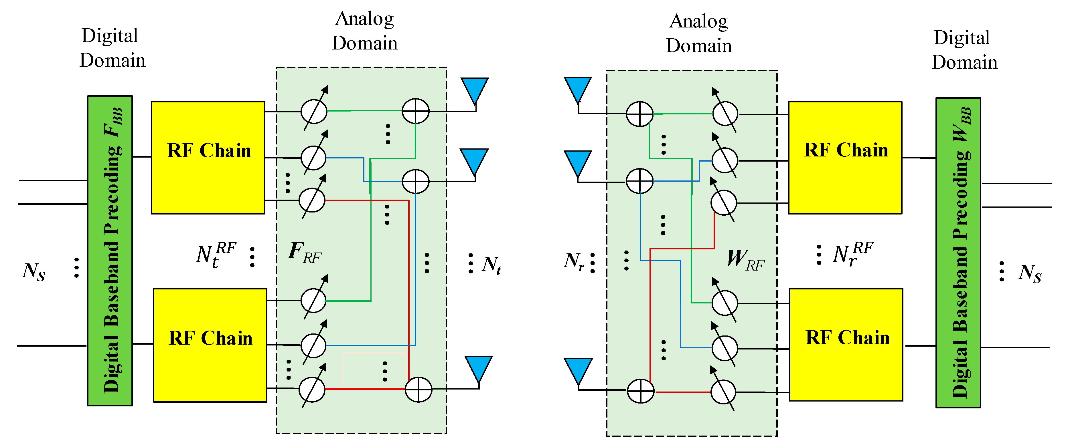
The system framework is shown in Figure 1. Consider a base station configured with transmit antennas and radio links using data streams, data communication with users configuring receiver antennas, and links. The number of data streams, antennas, and RF links at the transmitter and receiver satisfies , respectively.
Where: uppercase letter represents the matrix, and lowercase letter represents the column vector. represents the inverse of matrix ; indicates the conjugate transpose of the matrix ; diag(⋅) denotes a diagonal matrix; [:,[1: ]] takes the first column of matrix ; represents the Frobenius norm of matrix ; indicates the pseudoinverse of ; Tr() represents the trace of matrix .
The modulated symbol is first processed by digital beamforming matrix for the baseband signal, and the processed signal is then subjected to analog beamforming matrix to form the final transmitted signal:
where .
In this paper, using the Saleh–Valenzuela channel model [12,13,14,15,16], represents the downlink channel matrix, then received signal is expressed as:
Among them, noise vector obeys a Gaussian distribution with a mean of 0 and a variance of , that is, .
and represent, respectively, the analog merge matrix and the digital merge matrix. Assuming that the transceiver knows the state information of the channel, received signal is processed by the signal in the analog domain and the digital domain. The received symbol vector can be expressed as:
Analog combining matrix and analog beamforming matrix are implemented by using a phase shifter with phase modulation at the transceiver end. Because of limited amplitude modulation capability, the analog beamforming matrix is used, and the combining matrix elements generally satisfy constant modulus constraint , . These constraints mean that the matrix elements are unit-normalized by taking the modulus that allows to represent them with unit amplitude. In the case where the channel state information (CSI) is known, the spectral efficiency [23] of the system can be expressed as:
where , represents the average transmit power of the sender.
2.2. Channel Model
A notable feature of mmWave communication is that the number of scatterers in the transmission path is relatively small, so the existing channel model [27] is not suitable for mmWave communication systems. The existing channel model is only intended for MIMO systems that do not address the sparse characteristics of channel and are also not applicable for mmWave bands. The channel model in [27] is also only for MIMO systems and not for massive MIMO systems, which motivated us to deploy the Saleh–Valenzuela Channel Model that has sparse characteristics, is suitable for low-rank channel estimation, and embodies the spatial correlation characteristics of mmWave communications. In response to this situation, the widely used Saleh–Valenzuela model was used [12,13,14,15,16], and mmWave channel matrix under this model can be expressed as:
where and represent the number of clusters and scatterers in each cluster, respectively. represents the gain coefficient of the lth path in the ith cluster. The gain coefficient satisfies the mean of 0, variance is , and . Where is a normalization factor that causes channel matrix to satisfy condition , the matrix representation of the channel matrix is
where
where and represent the azimuth and elevation angles of the angle of arrival (AoA) and the angle of departure (AoD), respectively. , are the antenna array response sequences of receiver and transmitter respectively, and the transmitting and receiving antenna arrays are arranged in a uniform planar array (UPA), so the corresponding antenna-array vector is:
where and are index values of the two-dimensional planar array, respectively; for the antenna array of the transceiver end, values of and are, respectively, , , where is the antenna spacing and is the signal wavelength.
2.3. Objective Function
In the traditional digital precoding structure, considering the complexity of the algorithm and the complexity of the mmWave MIMO system itself, the linear precoding algorithm is often used in practical systems. The MMSE algorithm is a commonly used method. The objective function in Equation (9) is obtained to calculate the final precoding matrix:
subject to:
where satisfies the power-limit requirement of the transmitter, and represents the average power of the transmitter.
For a hybrid beamforming structure with two stages of processing, by using the Frobenius norm on Equation (3) and taking the trace value of , the objective function in Equation (9) can be further written as:
The proposed algorithm is further equivalent to the objective function in Equation (10), and iteratively obtains a hybrid beamforming algorithm with performance close to that of pure digital beamforming.
3. Proposed Algorithm
On the basis of the traditional MMSE algorithm, an alternating MMSE (Alt-MMSE) algorithm is proposed by using the orthogonality of the digital matrix and the idea of an iterative update. The algorithm first designs the initial digital matrix, iterates on this basis to update, and finally obtains a hybrid beamforming matrix.
3.1. Initial Digital Beamforming Matrix Design
Perform singular-value decomposition (SVD) on channel matrix :
where is the order matrix, is the order singular value matrix, and is the order matrix. Take front column of matrix as a pure digital beamforming matrix .
In the hybrid beamforming structure, since there is a two-stage beamforming matrix, the traditional MMSE algorithm cannot be directly used, so the equivalent matrix is used to obtain the initial digital matrix:
where and singular-value decomposition of equivalent channel matrix , then:
In order to make the performance of the algorithm closer to that of the pure digital beamforming matrix, let:
The argument can be obtained as:
An analog beamforming matrix that satisfies the constant-modulus requirement can be obtained from Equation (15).
3.2. Algorithm Design
The purpose of the proposed algorithm is to reduce the minimum mean square error (MMSE) of the transmitted and received signals. On the basis of the initial digital matrix, the orthogonal function of the digital matrix was used to further simplify the objective function in Equation (10). Multiple iterations were performed to finally obtain a hybrid beamforming matrix. Expanding the objective function in Equation (10), we get [21,28,29]:
where , and .
Utilizing the orthogonality of the digital beamforming matrix, namely, , Equation (16), assuming is known, can be further transformed to:
subject to
The MMSE of the transmitted and received signals can be approximated by Equation (18), which is known by Herder’s inequality:
subject to
The equation holds only when satisfies Equation (19):
where . Since each element of the analog matrix satisfies the constant-modulus requirement, the analog wave obtained according to Equation (15), the phase information of each element value of the beam-shaping matrix can further obtain analog matrix , . Updated digital matrix and analog matrix are used as the initial conditions for the next update. In each iteration process, the analog matrix satisfying the constant-modulus requirement is obtained by using Equation (15), so that the designed hybrid beamforming is performed. The matrix approximates the pure digital beamforming matrix to improve the performance of the system. The specific algorithm is as follows.
| Algorithm 1 Alt-MMSE Algorithm. |
| Input: , , 1: Determine 2: Calculate the SVD of according to Equations (11) and (19) 3: Determine according to Equations (12) and (13) 4: 5: 6: Calculate according to Equation (16) 7: Obtain the SVD of 8: Determine according to Equation (19) 9: Obtain the argument of using Equation (15) 10: Calculate 11: Calculate the SVD of 12: Determine using the method of Equation (19) 13: Obtain the argument of using the method of Equation (15) 14: 15: end 16: Determine , 17: return ,, , |
4. Simulation Results
In this paper, the performance of the proposed Alt-MMSE algorithm was verified by simulation with different numbers of data streams, a different number of RF links, and Signal-to-noise ratio (SNR) = 0 dB, and compared with pure digital beamforming, the OMP hybrid beamforming algorithm [20], and other references [18,19,24]. The specific simulation parameters are shown in Table 1.
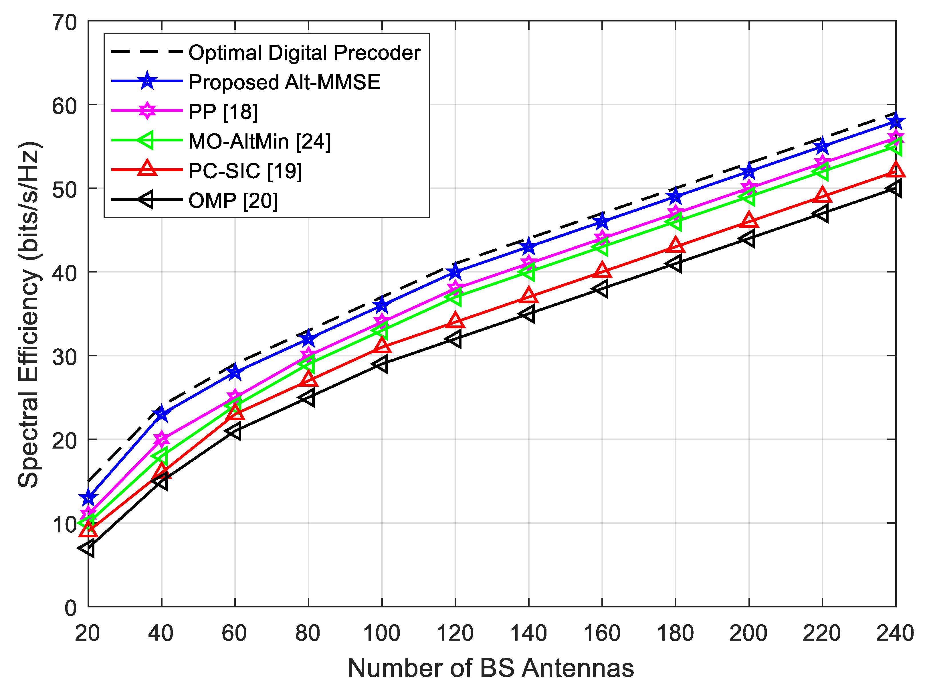
4.1. Spectral Efficiency Analysis when
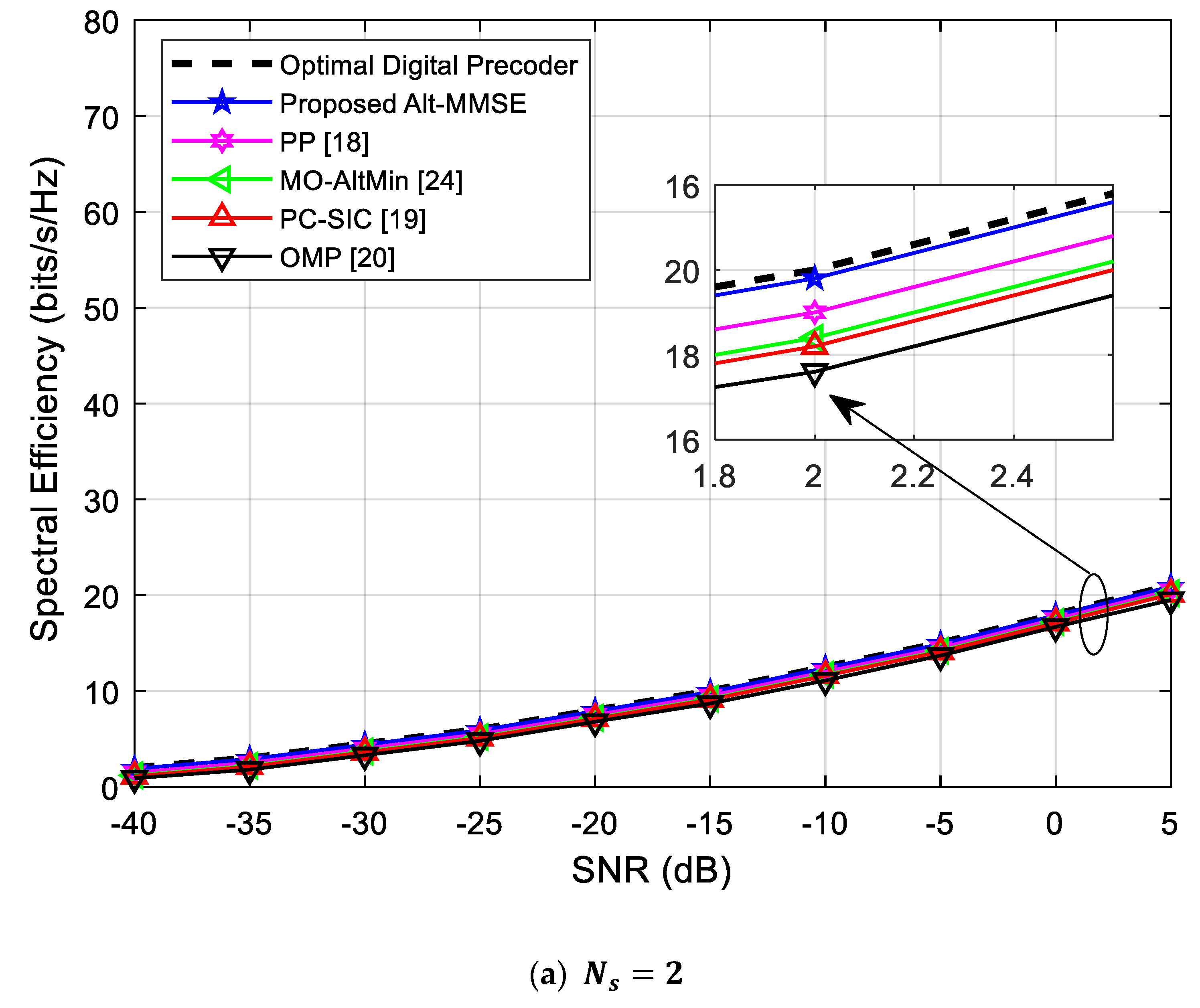
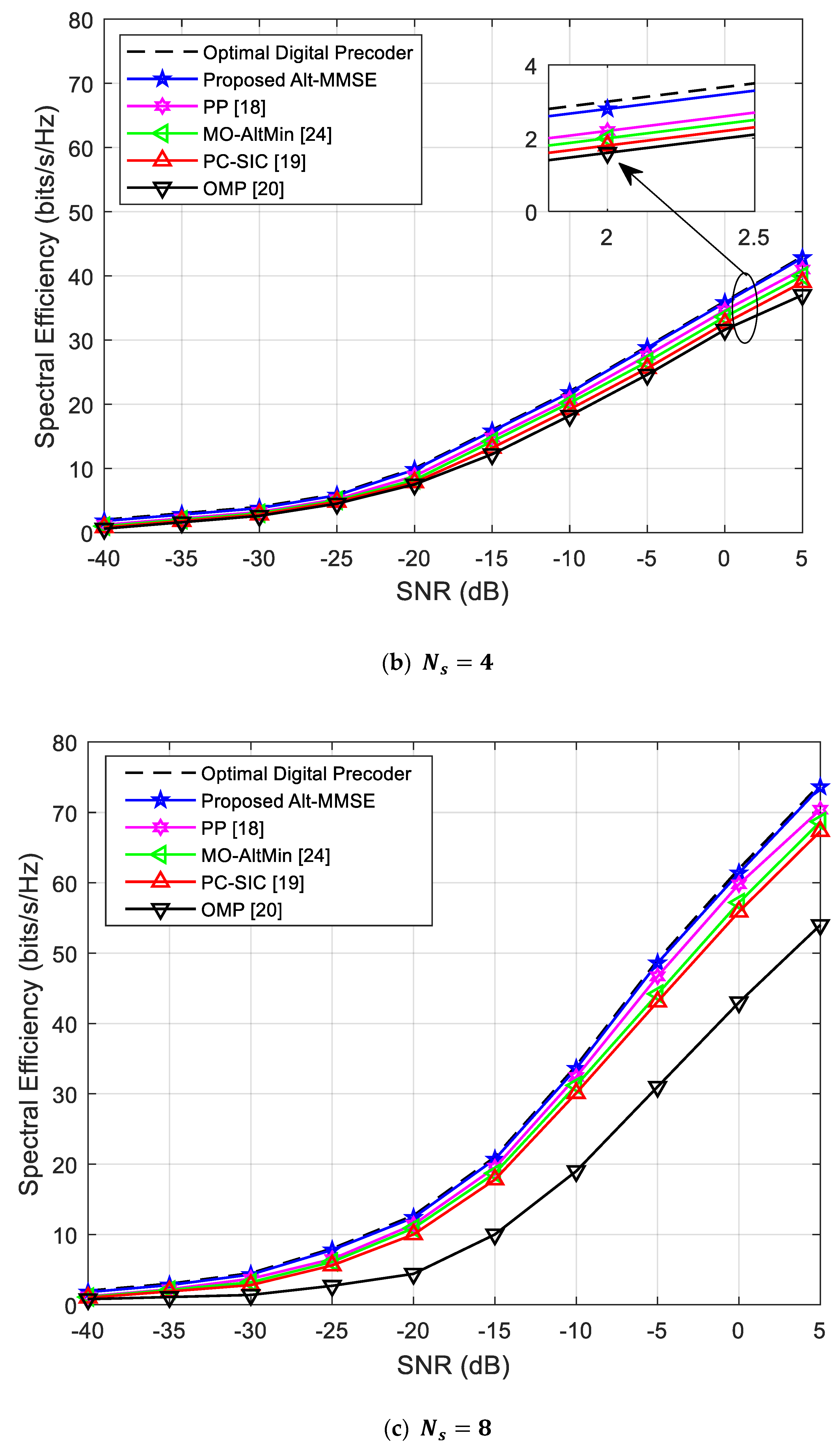
Figure 2 shows the system performance as an SNR function when the number of RF chains and number of data streams for the Alt-MMSE algorithm, pure digital beamforming algorithm, OMP algorithm [20], Phase Pursuit [18], MO-AltMin [24], and PC-SIC [19]. It can be seen from Figure 2 that, when the number of data streams is small, the performance difference of the algorithms is not large, but as the number of data streams increases, the performance gap between the algorithms becomes increasingly obvious, and the performance of the Alt-MMSE algorithm is more obviously and significantly better than the performance of the other algorithms, and closer to the performance of pure digital beamforming. The simulation showed that the performance advantage of the Alt-MMSE algorithm is significantly greater than that of other beamforming algorithms [16,17,18,19,20,24] when number of data streams is large.
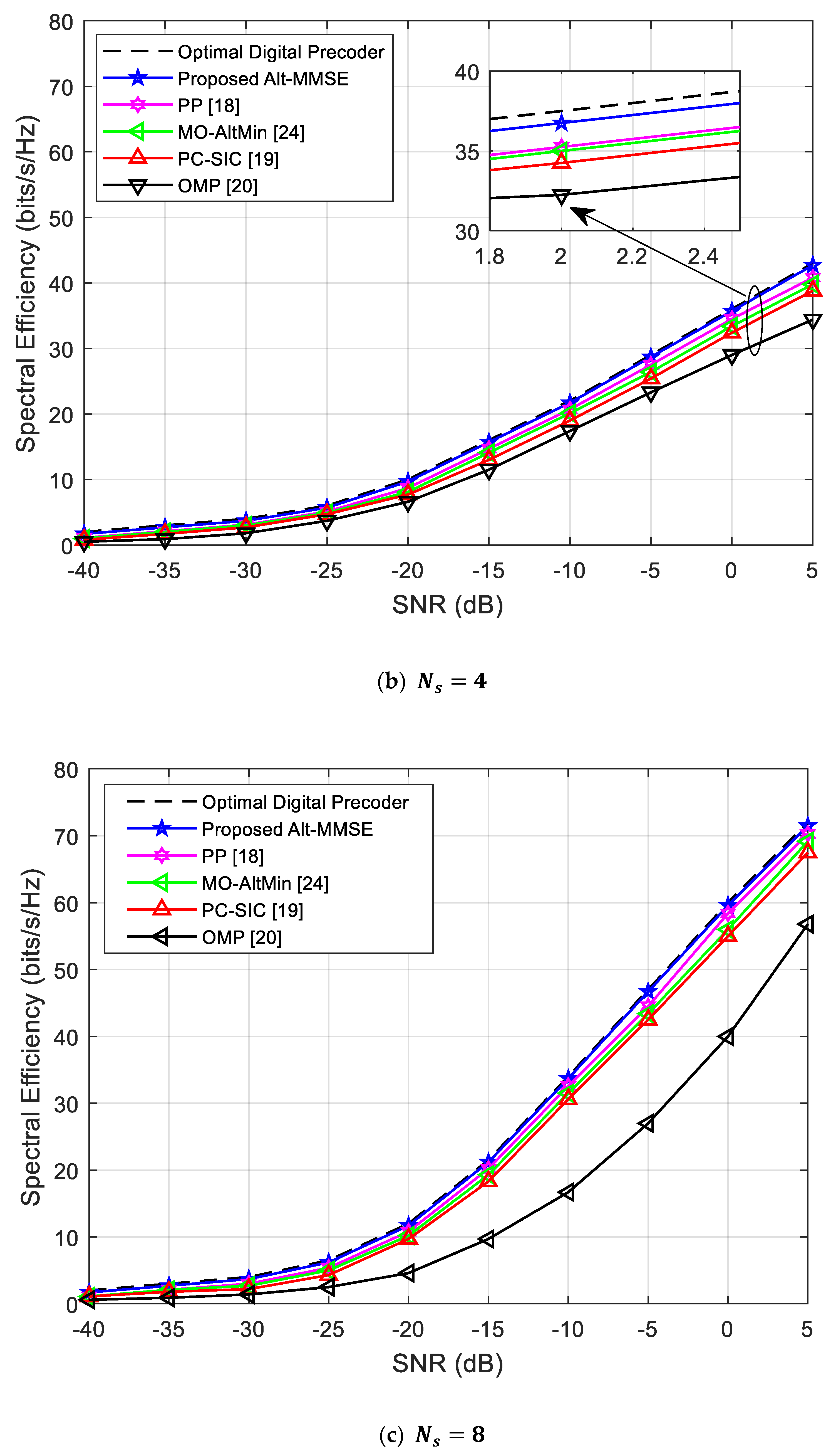
4.2. Spectral Efficiency Analysis when
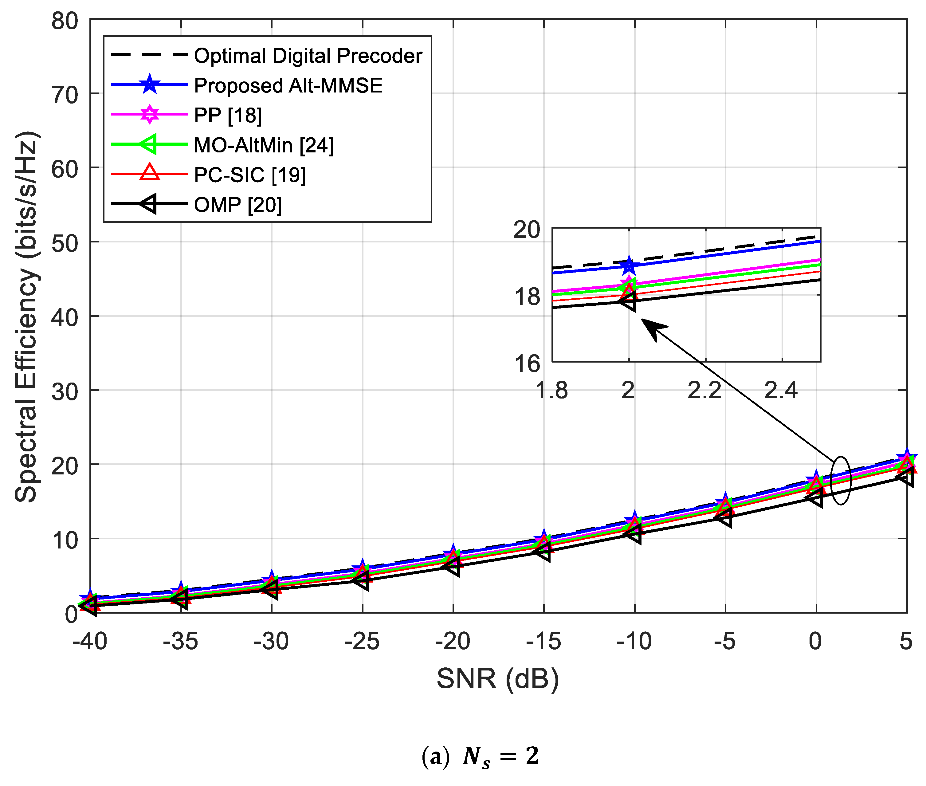
Figure 3 shows the system performance of the algorithms as a function of SNR at . It can be seen from Figure 3 that, when number of data streams is equal to the number of RF links (), the performance of the OMP-based hybrid beamforming algorithm is significantly lower than that of pure digital beamforming, and the gap becomes increasingly obvious as number of data streams increases. The performance of the proposed algorithm is always better than the performance of the other existing algorithms, and is very close to the system performance of the pure digital beamforming algorithm. It can be seen that the relationship between number of RF chains and number of data streams also affects the performance of the algorithm.
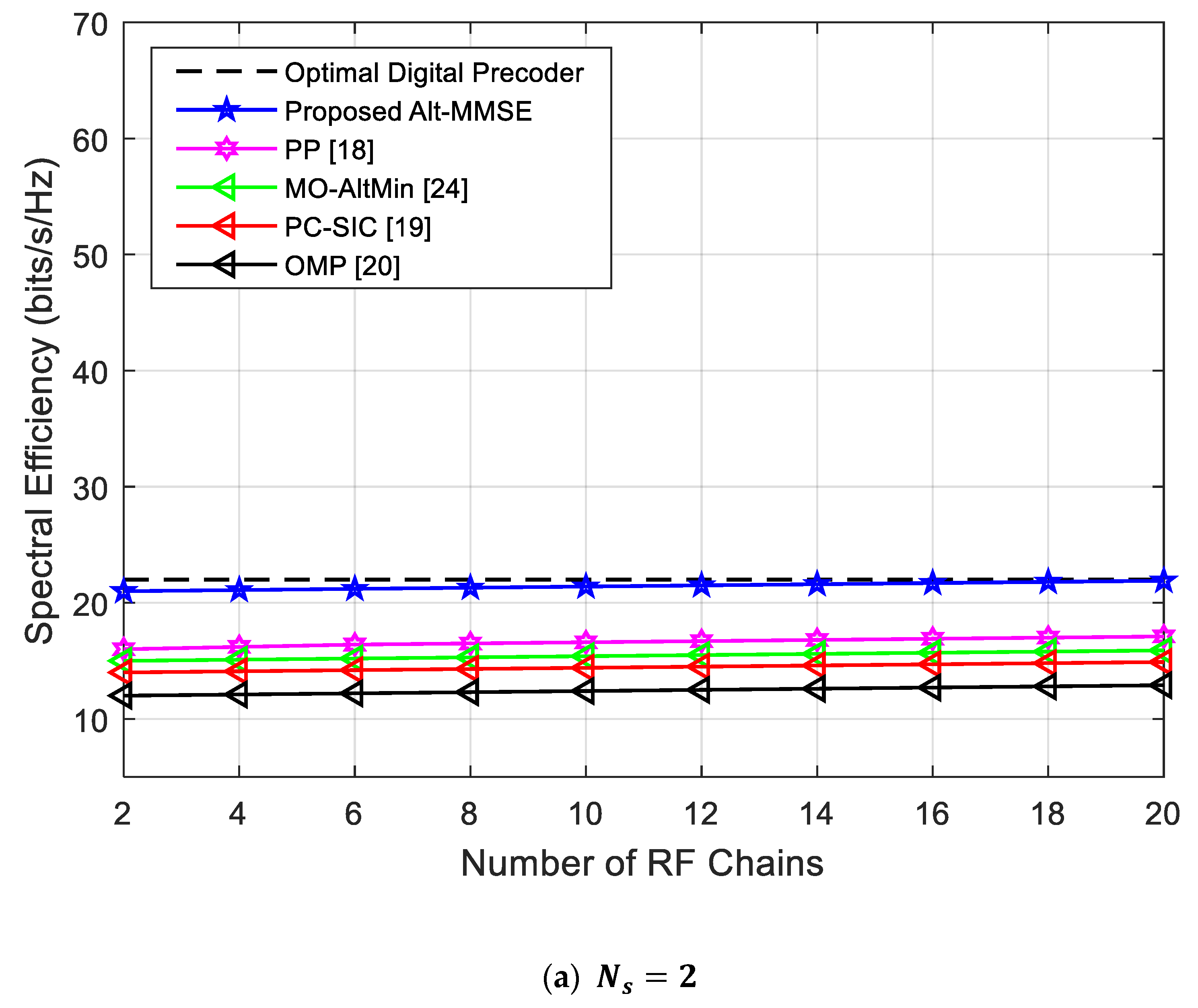
4.3. Impact of RF Chains
Figure 4 shows the performance of the algorithms as a function of the number of RF chains when SNR = 0 dB and . It can be seen from Figure 4 that, when the number of data streams is constant, the number of RF chains has significant impact on system performance. When the number of RF chains is small, the performance of the proposed Alt-MMSE algorithm has obvious advantages over the other algorithms. When , the performance curves of the two algorithms tend to be stable. Although the increase in the number of RF chains brings about an increase in system performance, it also brings about an increase in cost and power consumption. Therefore, in actual system applications, the impact of both on system performance should be comprehensively considered. In addition, Figure 4 further explains the impact of the number of different RF chains on system performance, as shown in Figure 2 and Figure 3. That is, when the number of data streams is the same, the larger the number of RF chains, the better the performance of the algorithm. This is also the main reason why the performance difference of algorithms in Figure 3 is greater than the performance difference between algorithms in Figure 2.
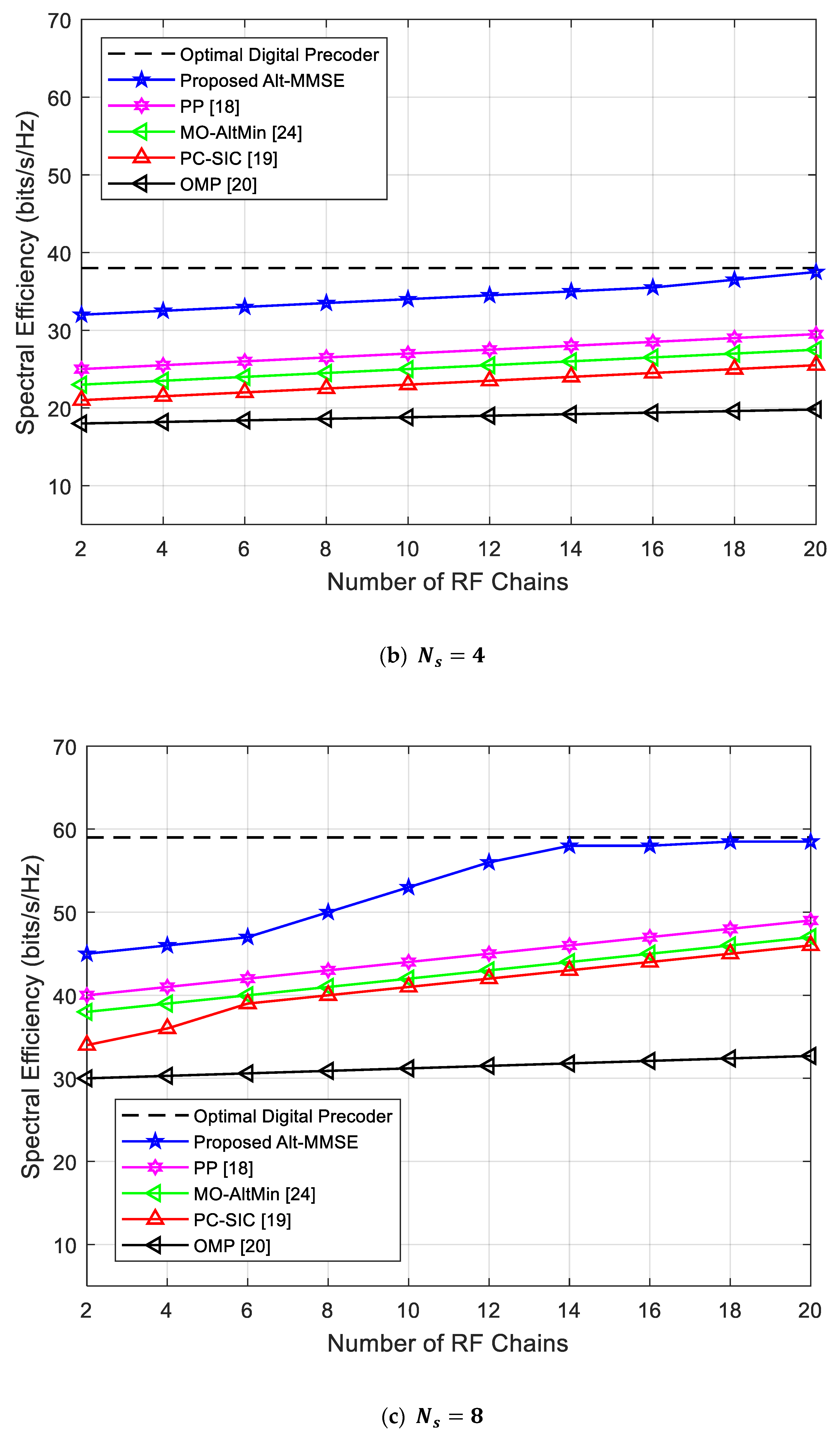
4.4. Impact of Antennas
The spectral efficiency of the proposed and other algorithms was analyzed against the number of BS antennas in Figure 5. As can be seen from Figure 5, the spectral efficiency of all algorithms increases by increasing the number of BS antennas. Moreover, the relative comparison shows that the spectral efficiency of the proposed Alt-MMSE algorithm was better than that of other algorithms [12,13,14,18], and it also had similar performance with the optimal digital precoding scheme, which makes it superior and useful for deploying in mmWave-MIMO systems. To further elaborate on the effectiveness of the proposed scheme, the spectral efficiency at 180 BS antennas was evaluated. As can be seen from the results, the spectral efficiency of the proposed scheme was about 48 bits/s/Hz, whereas the spectral efficiency of the PP [12], MO-AltMin [13], PC-SIC [18], and OMP [14] schemes was 45, 44, 42, and 41 bits/s/Hz, respectively.
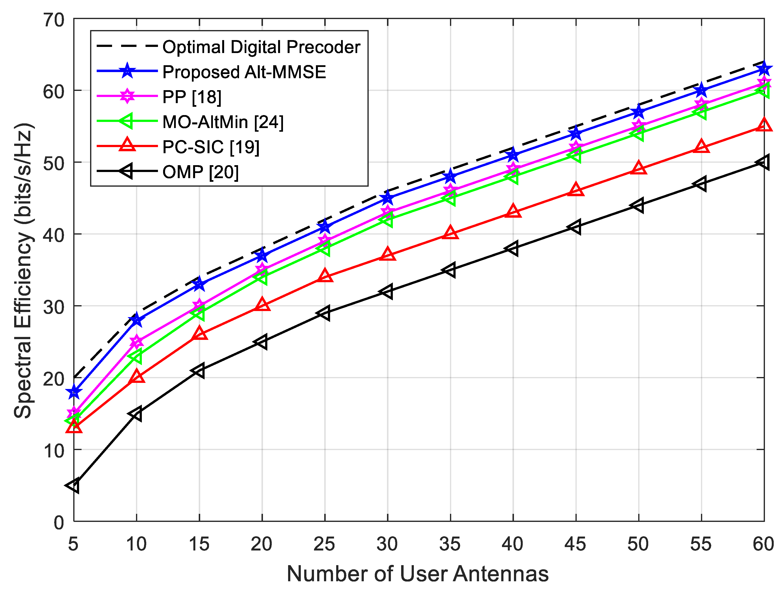
To analyze the impact of the number of user antennas on spectral efficiency, Figure 6 compares it against the number of user antennas with SNR = 0 dB. It can be seen from Figure 6 that the proposed Alt-MMSE algorithm showed better spectral efficiency than existing competing alternatives [12,13,14,18] at each number of user antennas, which makes it robust for multiple-user scenarios. Moreover, the rate gap between the proposed scheme and the OMP [14] scheme was much larger, showing the poor performance of the OMP scheme when increasing the number of user antennas. To clarify it further, we checked the spectral efficiency of the proposed scheme and the OMP scheme when the number of user antennas is 60. As can be seen from Figure 6, the SE of the proposed algorithm was about 62 bits/s/Hz, whereas the SE of the OMP algorithm was about 50 bits/s/Hz, which means an increase of 12 bits/s/Hz.
4.5. Energy Efficiency Analysis
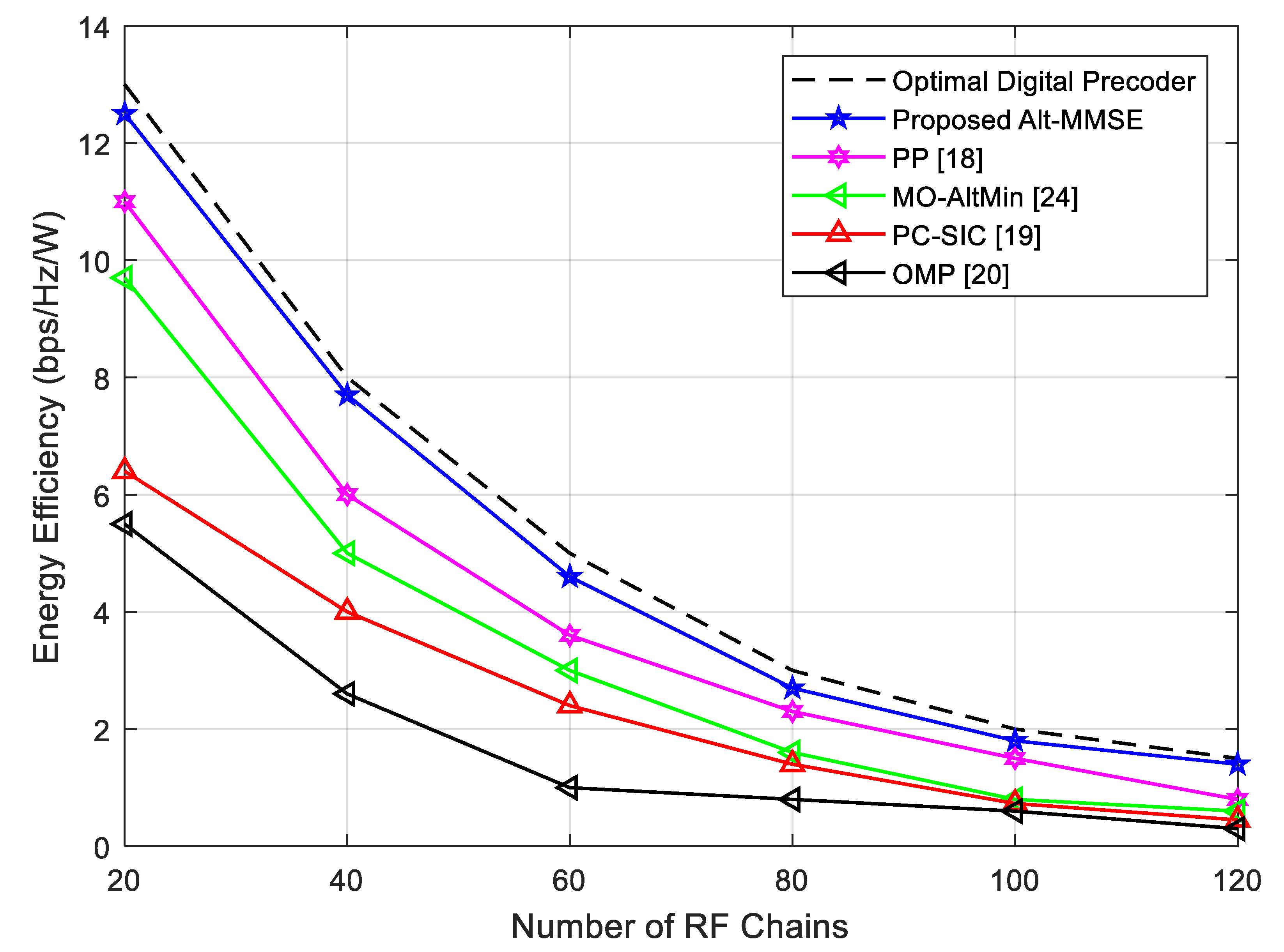
To evaluate the energy efficiency aspect of the proposed scheme, Figure 7 compares the energy efficiency of the proposed scheme with other state-of-the-art schemes against the number of RF chains. As can be seen from Figure 7, the energy efficiency of the proposed and all other schemes decreases with an increasing number of RF chains, but as indicated by its curves, the proposed Alt-MMSE schemes had better energy efficiency than that of the other algorithms [12,13,14,18]. Moreover, the proposed schemes had similar energy-efficiency performance with optimal digital precoding, making it more suitable for low-energy requirements. This also gives us important information about the impact of energy consumption on system complexity. As the proposed algorithm has less power consumption, its corresponding hardware is less complex, and faster.
4.6. Bit Error Rate (BER) Analysis
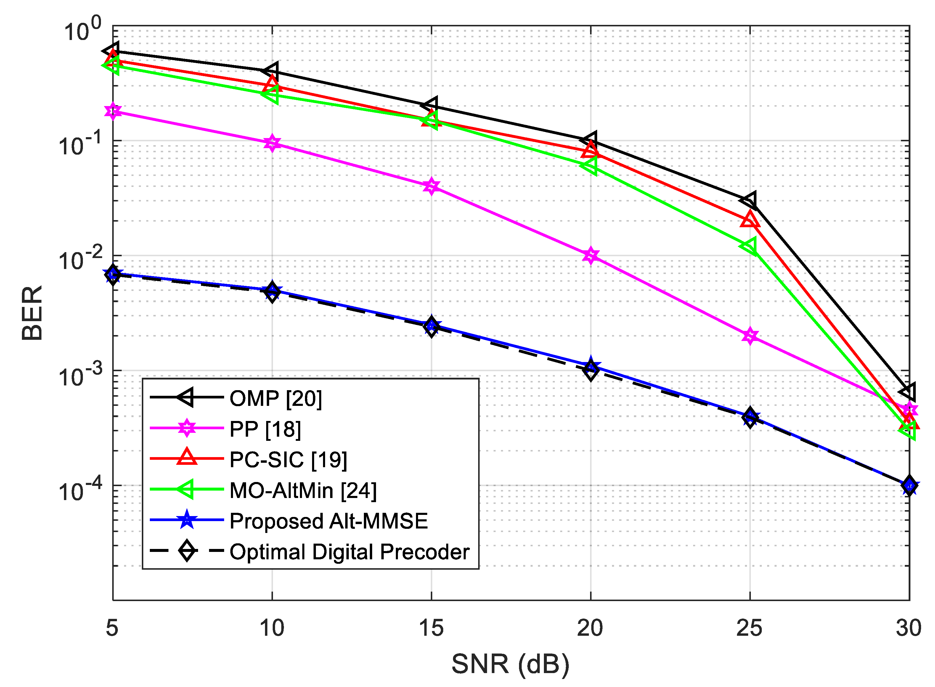
To evaluate the robustness of the proposed scheme, this section compares the BER of the proposed algorithm with the existing reference algorithms under different SNR values. The results are illustrated in Figure 8. As can be seen from the results of Figure 8, the proposed algorithm showed better BER performance and was similar to the optimal fully digital precoding algorithm. This means that the proposed algorithm gave good channel quality and better QoS to subscribers as compared with existing algorithms. It also gives important evidence that the proposed algorithm is robust to channel impairments, such as cochannel interference and noise accumulations, as compared with existing algorithms.
5. Complexity Analysis
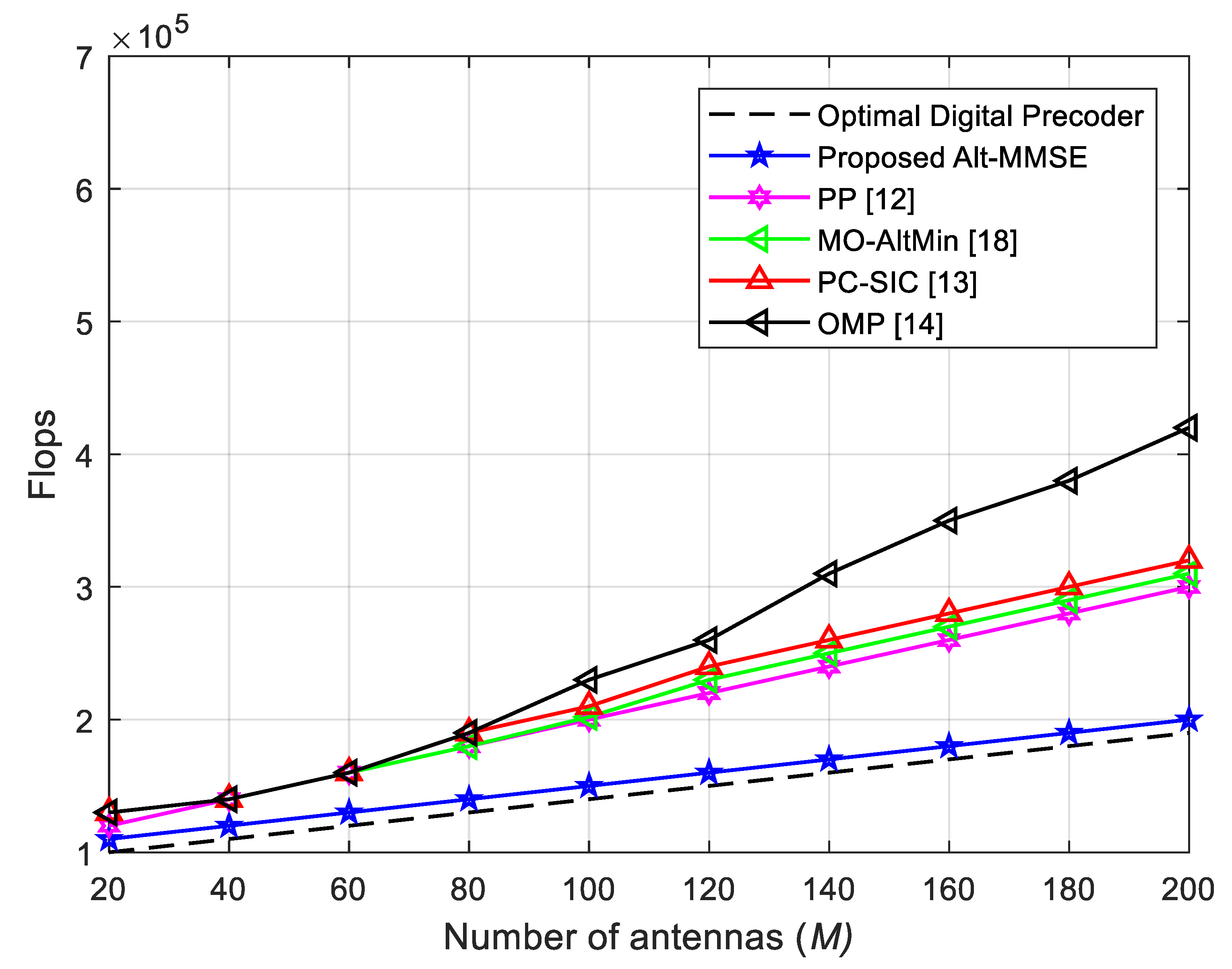
In this section, the complexity of the algorithms is compared and analyzed under conditions given in Section 4 [28,29]. The OMP hybrid beamforming algorithm in [20] utilizes the error matrix of pure digital matrix and hybrid beamforming matrix to iteratively update the hybrid beamforming matrix from the candidate set. Its algorithm complexity is mainly calculated by the candidate set and the error matrix. Correlation determines and selects the appropriate analog beamforming vector with a complexity of . The MD-HP algorithm in [24] uses phase information of analog matrix to update the process of digital matrix , which involves the pseudoinverse of the analog matrix. Its algorithm complexity is . The proposed Alt-MMSE algorithm is different from the above two algorithms. The phase information of analog matrix is obtained by matrix , and the analog beamforming matrix is constructed. The algorithm complexity is mainly from Algorithm 1, Step 5, for calculation of the equivalent matrix, so the complexity of the proposed Alt-MMSE algorithm is . In the actual system, since , the proposed Alt-MMSE algorithm has lower complexity than that of the OMP [20] and MD-HP [24] algorithms. Figure 9 compares the number of flops required for algorithms under an increasing number of BS antennas. As can be seen from Figure 9, the proposed Alt-MMSE algorithm requires a smaller number of flops as compared with existing algorithms and has similar complexity performance with that of the optimal digital precoding algorithm. This clearly indicates that the proposed algorithm was simpler to implement than the traditional algorithms, and it is robust in performance. Table 2 summarizes the complexities of the algorithms.
6. Conclusions
In this paper, the hybrid beamforming problem in millimeter-wave MIMO systems was studied. In order to obtain system performance similar to that of pure digital beamforming, an iteratively updated minimum mean square error algorithm was proposed. The algorithm uses the orthogonality of the initial digital matrix on the basis of the digital matrix. Compared with the classical OMP algorithm and the approximate optimal MD-HP algorithm in [24], the proposed algorithm system performance was significantly better than that of the OMP algorithm [20], especially when the number of RF links was equal to the number of data streams and the number was small. The performance of the proposed algorithm always approximates the performance of pure digital beamforming. Compared with the approximate optimal MD-HP scheme, the proposed performance was slightly better than that of the MD-HP algorithm, and both were close to the performance of pure digital beamforming. In terms of algorithm complexity, the proposed Alt-MMSE hybrid beamforming had lower complexity than the OMP and MD-HP algorithms. The next study will extend this work, and comprehensively analyze the impact of cost and power consumption on system performance.
Author Contributions
Conceptualization, S.L.M. and I.K.; methodology, M.H.A.; software, M.A.; validation, M.H.A.; formal analysis, S.L.M.; investigation, M.A.; resources, M.H.A.; data curation, I.K.; writing—original-draft preparation, S.L.M.; writing—review and editing, I.K.; visualization, M.A.; supervision, M.H.A; project administration, S.L.M.; I.K.; funding acquisition, M.H.A.
Funding
This research received no external funding.
Conflicts of Interest
The authors declare no conflict of interest.
References
- Zhou, B.; Liu, A.; Lau, V. Successive localization and beamforming in 5G mmWave MIMO communication systems. IEEE Trans. Signal Process. 2019, 67, 1620–1635. [Google Scholar] [CrossRef]
- Busari, S.A.; Huq, K.M.S.; Mumtaz, S.; Dai, L.; Rodriguez, J. Millimeter-wave massive MIMO communications for future wireless systems: A survey. IEEE Commun. Surv. Tutorials 2018, 20, 836–869. [Google Scholar] [CrossRef]
- Bjornson, E.; Perre, L.V.D.; Buzzi, S.; Larsson, E.G. Massive MIMO in sub-6 GHz and mmWave: Physical, practical, and use-case differences. IEEE Wirel. Commun. 2019, 26, 100–108. [Google Scholar] [CrossRef]
- Ahmed, I.; Khammari, H.; Shahid, A.; Musa, A. A Survey on Hybrid Beamforming Techniques in 5G: Architecture and System Model Perspectives. IEEE Comm. Sur. & Tut. 2018, 20, 3060–3097. [Google Scholar]
- Alsharif, M.H.; Nordin, R. A evolution towards fifth generation (5G) wireless networks: Current trends and challenges in the deployment of millimetre wave, massive MIMO, and small cells. Telecommun. Syst. 2017, 64, 617–637. [Google Scholar] [CrossRef]
- Alemaishat, S.; Saraereh, A.O.; Khan, I.; Affes, S.H.; Li, X.; Lee, J.W. An efficient precoding scheme for millimeter-wave massive MIMO systems. Electronics 2019, 8, 927. [Google Scholar] [CrossRef]
- Cacciapuoti, S.A.; Sankhe, K.; Caleffi, M.; Chowdhury, K.R. Beyond 5G: THz-based medium access protocol for mobile heterogeneous networks. IEEE Commun. Mag. 2018, 56, 110–115. [Google Scholar] [CrossRef]
- Andrews, J.G.; Bai, T.; Kulkarni, M.N.; Alkhateeb, A.; Gupta, A.K.; Heath, R.W. Modeling and anayalzing millimeter wave cellular systems. IEEE Trans. Commun. 2017, 65, 403–430. [Google Scholar]
- Alsharif, M.H.; Nordin, R.; Shakir, M.M.; Ramly, A.M. Small cells integration with the macro-cell LTE cellular networks and potential extension for 5G. J. Electr. Eng. Technol. 2019, 14, 2455–2465. [Google Scholar] [CrossRef]
- Cacciapioti, A.S. Mobility-aware user association for 5G mmWave networks. IEEE Access 2017, 5, 21497–21507. [Google Scholar] [CrossRef]
- Alsharif, M.H.; Nordin, R.; Abdullah, N.F.; Kelechi, A.H. How to make key 5G wireless technologies environmental friendly: A review. Trans. Emerg. Telecommun. Technol. 2018, 29, e3254. [Google Scholar] [CrossRef]
- Psomas, C.; Krikidis, I. Low-complexity base station selection scheme in mmWave cellular networks. IEEE Trans. Commun. 2017, 65, 4049–4064. [Google Scholar]
- Yang, B.; Yu, Z.; Lan, J.; Zhang, R.; Zhou, J.; Hong, W. Digital beamforming-based massive MIMO transceiver for 5G millimeter-wave communications. IEEE Trans. Microw. Theory Tech. 2018, 66, 3403–3418. [Google Scholar] [CrossRef]
- Bangash, K.; Khan, I.; Lloret, J.; Leon, A. A joint approach for low-complexity channel estimation in 5G massive MIMO systems. Electronics 2018, 7, 218. [Google Scholar] [CrossRef]
- Eltayeb, M.E.; Al-Naffouri, T.Y.; Heath, R.W. Compressive sensing for millimeter-wave antenna array diagnosis. IEEE Trans. Commun. 2018, 66, 2708–2721. [Google Scholar] [CrossRef]
- Khan, I.; Zafar, M.H.; Ashraf, M.; Kim, S. Computationally efficient channel estimation in 5G massive multiple-input multiple-output systems. Electronics 2018, 7, 382. [Google Scholar] [CrossRef]
- Andrews, J.G.; Buzzi, S.; Wan, C.; Hanly, S.V.; Lozano, A.; Soong, A.C.K.; Zhang, J.C. What will 5G be? IEEE J. Sel. Areas Commun. 2014, 32, 1065–1082. [Google Scholar] [CrossRef]
- Wang, Y.; Zou, W. Low complexity hybrid precoder design for millimeter wave MIMO systems. IEEE Commun. Lett. 2019, 23, 1259–1262. [Google Scholar] [CrossRef]
- Liu, Y.; Feng, Q.; Wu, Q.; Zhang, Y.; Jin, M.; Qiu, T. Energy-efficient hybrid precoding with low complexity for mmWave massive MIMO systems. IEEE Access 2019, 7, 95021–95032. [Google Scholar] [CrossRef]
- El, A.O.; Rajagopal, S.; Abu-Aurra, S.; Pi, Z.; Heath, R.W. Spatially sparse precoding in millimeter-wave MIMO systems. IEEE Trans. Wirel. Commun. 2013, 130, 1499–1513. [Google Scholar]
- Jiang, J.; Lei, M.; Hou, H. Downlink Multiuser Hybrid Beamforming for mmWave Massive MIMO-NOMA System with Imperfect CSI. Int. J. Antennas Propag. 2019, 9764958, 1–10. [Google Scholar] [CrossRef]
- TSANG, Y.M.; Poon, A.S.Y.; Addepalli, S. Coding the BEAMS: Improving beamforming training in mmWave communication system. In Proceedings of the IEEE Global Telecommunications Conference, Houston, TX, USA, 5–9 December 2011; pp. 1–6. [Google Scholar]
- Sohrabi, F.; Yu, W. Hybrid digital and analog beamforming design for large-scale antenna arrays. IEEE J. Sel. Top. Signal Process. 2016, 10, 501–513. [Google Scholar] [CrossRef]
- Yu, X.; Shen, J.C.; Zhang, J.; Letaief, K.B. Alternating minimization algorithms for hybrid precoding in millimeter wave MIMO systems. IEEE J. Sel. Top. Signal Process. 2016, 10, 485–500. [Google Scholar] [CrossRef]
- Singh, J.; Ramakrishna, S. On the feasibility of codebook-based beamforming in millimeter wave systems with multiple antenna arrays. IEEE Trans. Wirel. Commun. 2014, 14, 2670–2683. [Google Scholar] [CrossRef]
- Dai, L.; Gao, X.; Quanl, J.; Han, S.; I, C.-L. Near-optimal hybrid analog and digital precoding for downlink mmwave massive MIMO systems. In Proceedings of the IEEE International Conference on Communications (ICC), London, UK, 8–12 June 2015; pp. 1334–1339. [Google Scholar]
- Verma, R.; Mahajan, S.; Rohita, V. Classification of MIMO channel models. In Proceedings of the 16th IEEE International Conference on Networks, New Delhi, India, 12–14 December 2008; pp. 1–4. [Google Scholar]
- Vitanyi, P. Analysis of sorting algorithms by kolmogorov complexity (a survey). Entropy Search Complex. 2007, 16, 209–232. [Google Scholar]
- Hanif, M.; Yang, H.C.; Boudrea, G.; Sich, E.; Seyedmehdi, H. Low-complexity hybrid precoding for multi-user massive MIMO systems: A hybrid EGT/ZF approach. IET Commun. 2017, 11, 765–771. [Google Scholar] [CrossRef]
Figure 1.
Proposed framework for millimeter-wave (mmWave) MIMO system.

Figure 2.
System performance when number of RF links , and number of streams .


Figure 3.
System performance when number of data streams equals RF links ().


Figure 4.
System performance when number of data streams is and SNR 0 dB.


Figure 5.
Comparison of spectral efficiency against number of BS antennas with 8 RF chains and SNR = 0 dB.
Figure 5.
Comparison of spectral efficiency against number of BS antennas with 8 RF chains and SNR = 0 dB.

Figure 6.
Comparison of spectral efficiency against the number of user antennas with 8 RF chains and SNR = 0 dB.
Figure 6.
Comparison of spectral efficiency against the number of user antennas with 8 RF chains and SNR = 0 dB.

Figure 7.
Comparison of energy efficiency against number of RF chains.

Figure 8.
Bit error rate (BER) comparison of different algorithms under various SNR levels.

Figure 9.
Complexity analysis of algorithms with increasing number of BS antennas.


Table 1.
Simulation parameters.
| Parameter | Value |
|---|---|
| Number of transmitting antennas | 256 |
| Number of receiving antennas | 64 |
| Antenna arrangement | UPA |
| Antenna spacing (mm) | λ/2 |
| Number of clusters | 5 |
| Number of scatterers ray | 10 |
| Angle of Arrival (AoA), Angle of Departure (AoD) distribution | Laplacian |
| Number of data streams | 8 |
| Signal-to-noise ratio (SNR) | 30 dB |
© 2019 by the authors. Licensee MDPI, Basel, Switzerland. This article is an open access article distributed under the terms and conditions of the Creative Commons Attribution (CC BY) license (http://creativecommons.org/licenses/by/4.0/).
Share and Cite
MDPI and ACS Style
Mohammed, S.L.; Alsharif, M.H.; Gharghan, S.K.; Khan, I.; Albreem, M. Robust Hybrid Beamforming Scheme for Millimeter-Wave Massive-MIMO 5G Wireless Networks. Symmetry 2019, 11, 1424. https://0-doi-org.brum.beds.ac.uk/10.3390/sym11111424
AMA Style
Mohammed SL, Alsharif MH, Gharghan SK, Khan I, Albreem M. Robust Hybrid Beamforming Scheme for Millimeter-Wave Massive-MIMO 5G Wireless Networks. Symmetry. 2019; 11(11):1424. https://0-doi-org.brum.beds.ac.uk/10.3390/sym11111424
Chicago/Turabian StyleMohammed, Saleem Latteef, Mohammed H. Alsharif, Sadik Kamel Gharghan, Imran Khan, and Mahmoud Albreem. 2019. "Robust Hybrid Beamforming Scheme for Millimeter-Wave Massive-MIMO 5G Wireless Networks" Symmetry 11, no. 11: 1424. https://0-doi-org.brum.beds.ac.uk/10.3390/sym11111424
Note that from the first issue of 2016, this journal uses article numbers instead of page numbers. See further details here.