One-Plane Glide-Symmetric Holey Structures for Stop-Band and Refraction Index Reconfiguration


1
Department of Signals, Systems and Radiocommunications, Universidad Politécnica de Madrid, 28040 Madrid, Spain
2
Division of Electromagnetic Engineering, KTH Royal Institute of Technology, 10044 Stockholm, Sweden
*
Author to whom correspondence should be addressed.
Symmetry 2019, 11(4), 495; https://0-doi-org.brum.beds.ac.uk/10.3390/sym11040495
Submission received: 1 March 2019
/
Revised: 29 March 2019
/
Accepted: 1 April 2019
/
Published: 4 April 2019
(This article belongs to the Special Issue Higher Symmetries and Its Application in Microwave Technology, Antennas and Metamaterials)
Abstract
:This work presents a new configuration to create glide-symmetric structures in a single plane, which facilitates fabrication and avoids alignment problems in the assembly process compared to traditional glide-symmetric structures based on several planes. The proposed structures can be printed on the metal face of a dielectric substrate, which acts as a support. The article includes a parametric study based on dispersion diagrams on the appearance of stop-bands and phase-shifting by breaking the symmetry. In addition, a procedure to regenerate symmetry is proposed that may be useful for reconfigurable devices. Finally, the measured and simulated S parameters of 10 × 10 unit-cell structures are presented to illustrate the attenuation in these stop-bands and the refractive index of the propagation modes. The attenuation obtained is greater than 30 dB in the stop-band for the symmetry-broken prototype.
1. Introduction
The recent study of higher symmetries [1,2,3,4,5] was driven by a growing interest in the use of periodic structures to improve the electromagnetic properties of antennas and microwave devices. These symmetries were first investigated in the 1960s and 1970s for one-dimensional periodic structures [6,7,8], introducing the concepts of glide and screw (twist) symmetry. More recently, two-dimensional glide symmetries were proposed and studied, which are a particular case of higher symmetries, demonstrating great potential for modifying the dispersion properties of periodic structures [9,10]. Periodic glide-symmetric structures are obtained by translating and mirroring a unit cell with respect to the glide plane [11]. The theoretical analysis of some of these structures with glide symmetry was carried out using the Floquet theorem [12,13,14], which provides an effective tool for the analysis of periodic structures. Glide symmetries were successfully used to reduce the dispersion of periodic structures [15,16,17,18], to increase the equivalent refractive index [19,20,21,22], or to increase the band and attenuation of electromagnetic bandgaps [10,23,24,25]. For example, glide symmetry was proposed to produce lens antennas for fifth-generation (5G) communications [26,27], taking advantage of their ability to generate a higher refractive index, less dispersion, and more isotropy [9]. Preceding this work, all glide-symmetric structures proposed in the literature for parallel plate configurations have a horizontal plane of symmetry, perpendicular to the direction of propagation [9,10]. These configurations require two different planes that must be shifted with respect to the other, which complicates fabrication and can introduce alignment problems.
In this work, we propose a glide-symmetric structure in a single plane with ellipses as the main element on a dielectric substrate that acts as a support. Glide symmetry is achieved by placing the symmetry plane vertically, preserving the orthogonality with respect to the direction of propagation. The use of a dielectric substrate instead of an all-metal structure allows the introduction of additional degrees of freedom, including the ability to modify or break the glide symmetry in the case of using a substrate that may have different values of dielectric constant (e.g., liquid crystals [28]). The propagation takes place mainly in an air gap above the plane of the ellipses; thus, the losses that the dielectric substrate may introduce are low. The electromagnetic properties of the structure in terms of dispersion, stop-bands, or refractive index are determined by the orientation, size, and position of these ellipses.
This paper is organized in four sections. Section 2 shows the basic properties and parameters of the glide-symmetric unit cell and some examples of operation. It includes the possibility to regenerate the glide symmetry from a symmetry-broken structure, maintaining the value of all parameters. In Section 3, the performance of these new structures is illustrated by the S parameters of a complete design with 10 × 10 unit cells, comparing measurements and simulations. The extracted dispersion diagrams from measurements are compared with the simulated unit cells. Finally, Section 4 discusses the results and potential applications of the proposed structures.
2. Materials and Methods
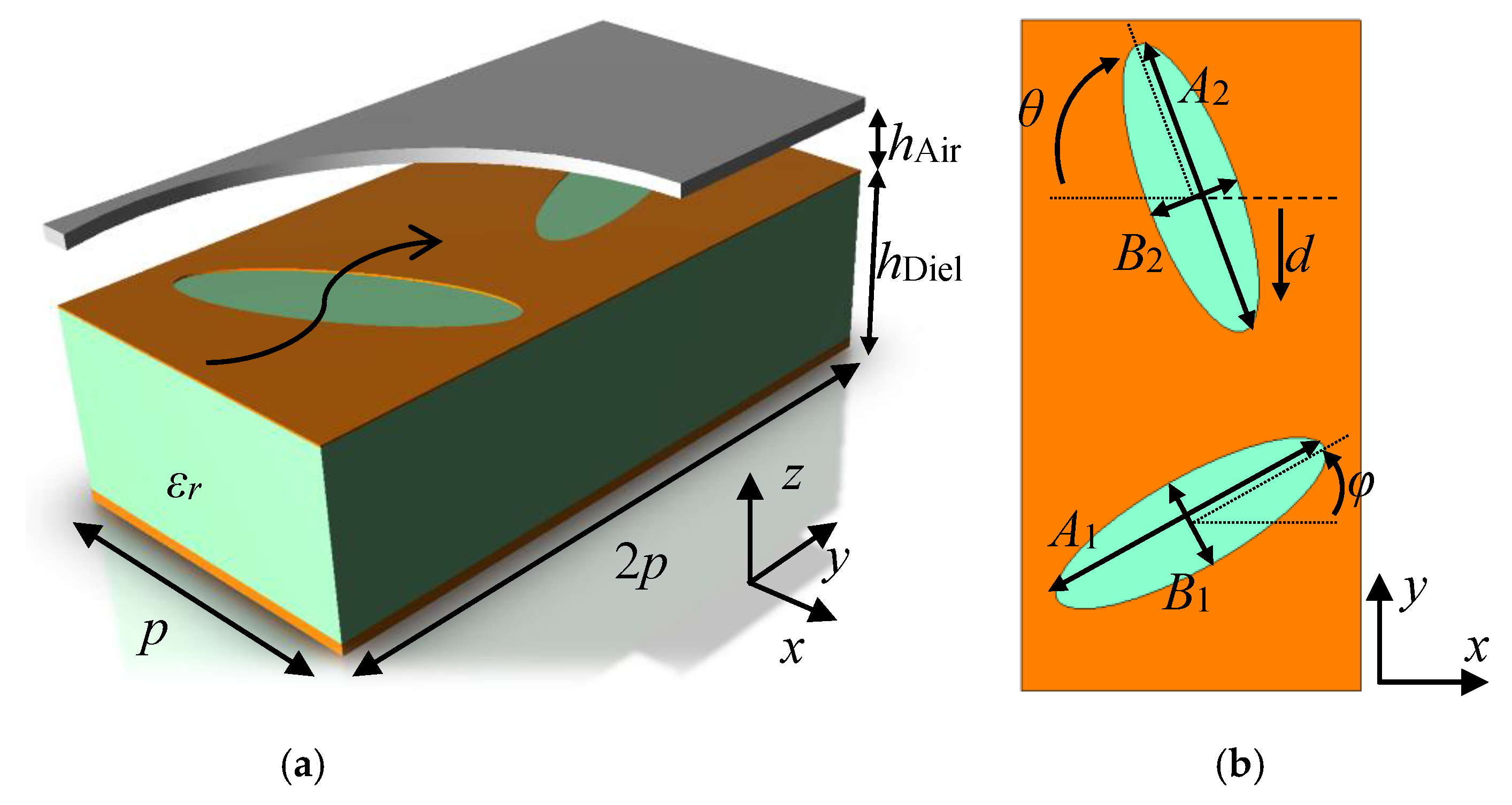
The studied structures consist of two metallic layers separated by a given air gap. The top layer is a smooth metal sheet, while the bottom layer contains the glide-symmetric ellipses printed on the metal surface of a dielectric substrate. This configuration generates conditions in the electromagnetic fields inside the air gap between metal sheets that cause modifications in the propagation and the appearance of stop-bands depending on the shape and orientation of the ellipses. Figure 1 represents the unit cell with all the parameters that define its electromagnetic behavior. Figure 1a shows the thicknesses of the air hAir and the dielectric substrate hDiel, together with the dielectric constant εr of the substrate and the period p. Periodic conditions in the x- and y-directions of the unit cell were applied to perform the dispersion analysis. The direction of propagation selected in the analysis extends along the y-axis, in which there are two periodicities to generate glide symmetry. In the perpendicular direction (x), there is only one periodicity. Figure 1b shows the parameters related to the size, position, orientation, and shape of the ellipses, which will determine the basic behavior of the whole structure. In particular, the sizes of the major and minor semi-axes of the ellipses are defined by the values of A1 and B1 for the first ellipse and A2 and B2 for the second ellipse. The parameters φ and θ define the angle of inclination of the first and second ellipses. A zero value means a horizontal position of the ellipses (semi-minor axis in the y-direction). Positive values of φ introduce counter-clockwise rotation for the first ellipse, and positive values of θ imply clockwise rotation for the second ellipse. Finally, the distance between ellipses can be modified by the displacement parameter d. The ellipses are kept at a distance equal to the periodicity p with d = 0, while values greater than zero mean that the second ellipse moved toward the first ellipse.
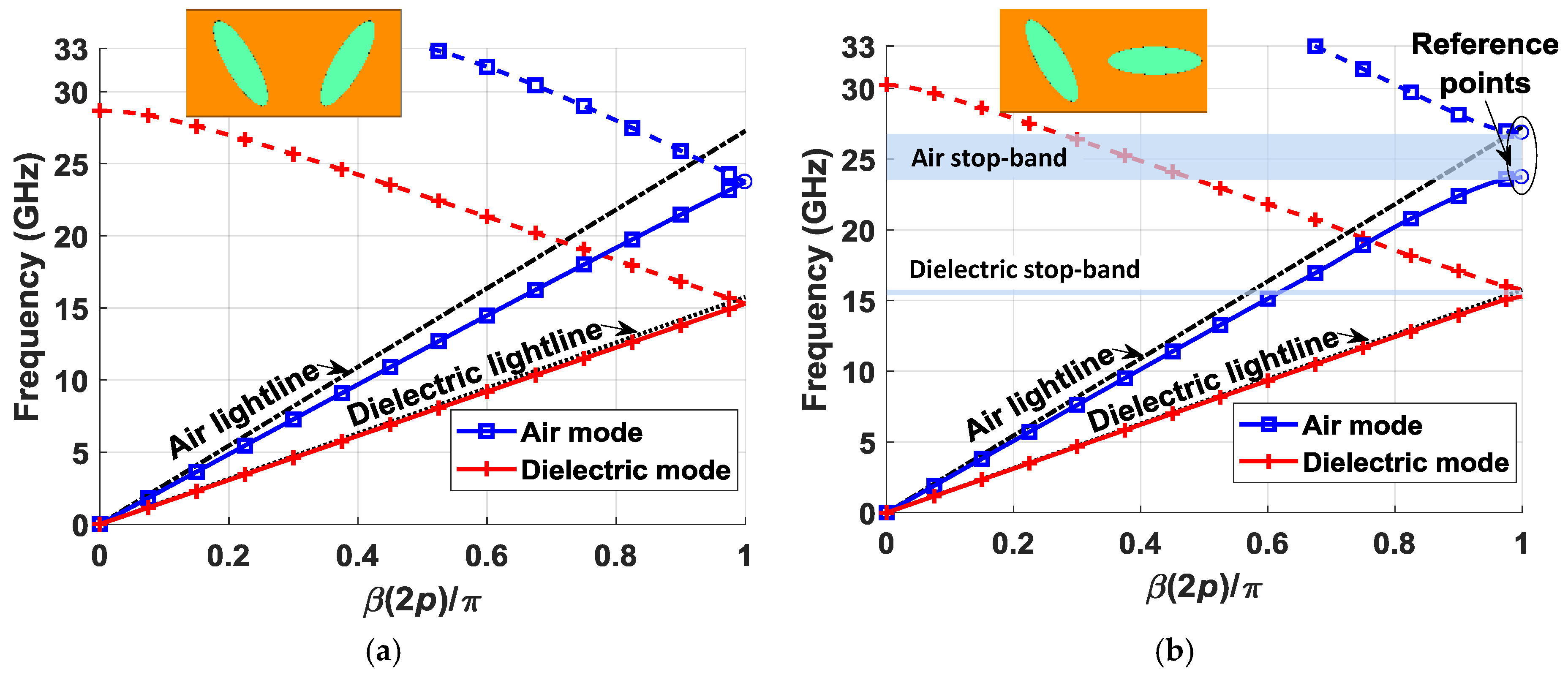
From the definition of the parameters presented in Figure 1, glide symmetry is achieved when A1 = A2, B1 = B2, φ = θ, and d = 0. The symmetry axis is at the center of the structure along the y-direction, and glide symmetry is obtained by reflecting the initial ellipse through the symmetry axis and displacing the ellipse obtained at a distance p in the y-direction. Figure 2 depicts an example of the operation of this structure. Figure 2a represents the dispersion diagrams of a structure with glide symmetry, and Figure 2b represents the same structure after breaking the symmetry with a modification of θ. In this work, all the dispersion analyses were carried out using the Eigenmode solver in CST Microwave Studio considering periodic boundaries in x- and y-directions, and electrical boundaries in the z-direction. Although there are available methods to quickly analyze glide symmetry based on the Floquet theorem [12,13,14] or equivalent circuits [11,29], these methods were not proposed to analyze this structure [30]. The dispersion diagrams only represent phase variations in the y-direction, as it is the direction in which the glide symmetry takes place. The chosen parameters for the case shown in Figure 2a are as follows: εr = 3, hAir = 0.3 mm, hDiel = 1.52 mm, p = 2.75 mm, A1 = A2 = 2.5 mm, B1 = B2 = 0.75 mm, φ = θ = 30°, and d = 0 mm. The value of θ is changed to 90° in the structure of Figure 2b.
Since the proposed structure is built in two different mediums, there are two fundamental modes of propagation, one in the air gap and one in the dielectric. The mode of interest in this case is the one that propagates in the air, as it has lower losses. An example of the dispersion curves of these modes is shown in Figure 2. For a glide configuration (Figure 2a), non-dispersive modes are obtained. However, the immediate effect of the rupture of the symmetry (Figure 2b) is the appearance of stop-bands or frequency ranges in which the fields do not propagate in the chosen direction. The stop-band appears in both the air and dielectric modes, but it is wider and its effect is more pronounced in the air mode. This is because the air gap is thinner than the thickness of the dielectric, and the electromagnetic fields confined inside are more influenced by the shape of the ellipses. The rupture of the symmetry generates a stop-band for the value β(2p)/π = 1 of the dispersion diagram, as expected from a periodic glide-symmetric structure with two periodicities [10]. The reference points indicated in Figure 2b represent the upper and lower limits of the stop-band, calculated for a 180° phase difference value between boundaries in the y-direction, which is equivalent to a value of 1 normalized with respect to period 2p of the structure. In the parametric studies carried out in Section 2.1, Section 2.2, Section 2.3 and Section 2.4, these reference points are used to show the behavior of the stop-band and the refractive index. The refractive index n is calculated as the ratio of the speed of light in vacuum, c, divided by the speed of light in the medium under study, v. Equations (1) and (2) demonstrate that this is equivalent to calculating the relationship between frequency in vacuum, fv, and frequency in the medium under study, fm, for any βv(2p)/π = βm(2p)/π value of the dispersion diagram, assuming that periodicity p is the same in both cases. Since βv(2p)/π = βm(2p)/π, we have λv = λm; thus, we get Equation (2).
Equation (2) implies that the refractive index increases if the frequency of the mode propagating in the medium under study decreases. In the studies carried out in this section, the frequency in vacuum for the reference point β(2p)/π = 1, with p = 2.75 mm, was 27.3 GHz.
The structure of Figure 2a was used as a reference for the parametric study (parameters: εr = 3, hAir = 0.3 mm, hDiel = 1.52 mm, p = 2.75 mm, A1 = A2 = 2.5 mm, B1 = B2 = 0.75 mm, φ = θ = 30°, and d = 0 mm). This section is subdivided into four main subsections, whereby each represents an alternative to break the symmetry and open stop-bands. Rupture of the symmetry is achieved by varying four fundamental parametric relationships: the size ratio between ellipses A2/A1, the vertical displacement of the second ellipse normalized with respect to the period d/p, the orientation of the ellipses φ and θ, and the relationship between semi-minor axis B1, B2 and semi-major axis A1, A2 of the ellipses. The graphs also include other parameters that do not play a role in breaking the symmetry, but that can intensify its effect. At the end of this section, the effect of varying the period p is presented, for glide and non-glide configurations. All graphs represent the reference points at the right side of the dispersion diagram (β(2p)/π = 1), as indicated in Figure 2. The continuous lines indicate the lower limit of the stop-band, while the dashed lines indicate the upper limit.
2.1. Symmetry Broken by the Ellipse Size
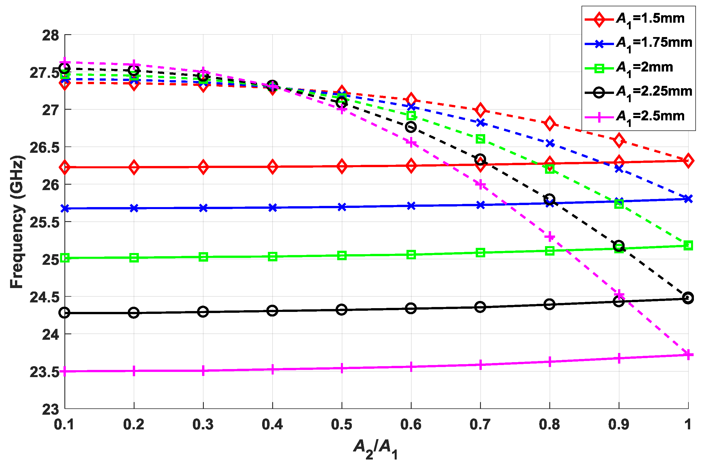
The first observed rupture of the symmetry occurs when the ellipse sizes are different. For simplicity, the relationship between the minor and major semi-axes is maintained constant (B1/A1 = B2/A2 = 0.3). In Figure 3, the stop-band opens when the second ellipse reduces its size, A2, to near zero while keeping the size A1 constant (A2/A1 = 0.1). It should be noted that the stop-band width begins to reach saturation for values less than A2/A1 = 0.5. This means that it is not necessary to reach very small ellipse sizes to achieve a larger stop-band, which facilitates the manufacturing. As expected, for an A2/A1 = 1 ratio, the glide symmetry is recovered and the stop-band is completely closed. Additionally, results are included for different sizes of the first ellipse (A1 from 1.5 mm to 2.5 mm). The value of the period p of the structure was kept constant at 2.75 mm. It can be seen how the reduction in size of this ellipse leads to narrower stop-bands. In addition, the refractive index of the structure increases as A1 increases. This is consistent, as the fields propagating in the air gap are most affected by the dielectric for larger ellipse sizes.
2.2. Symmetry Broken by the Displacement between Ellipses
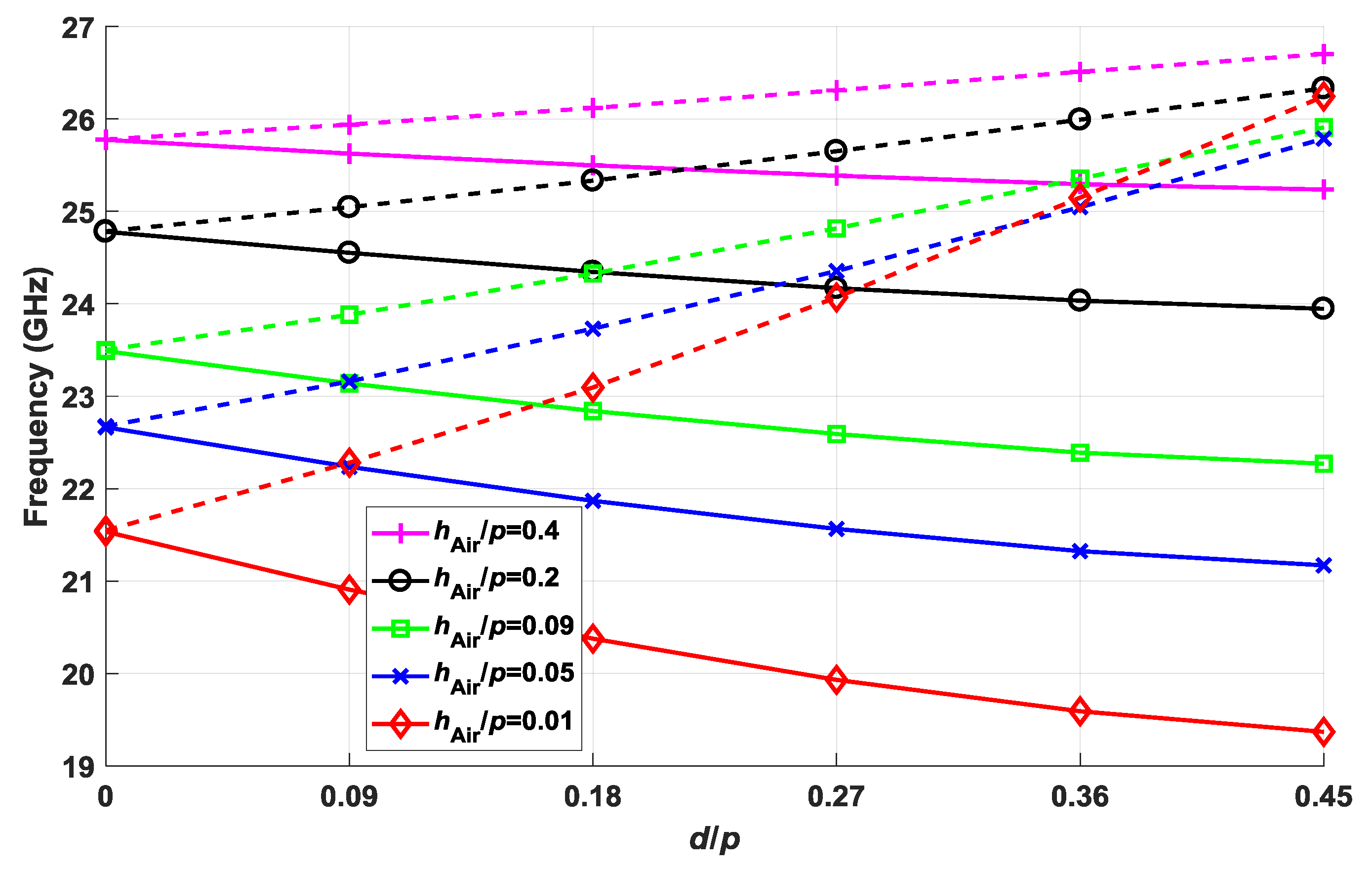
The second rupture of the symmetry relates to the displacement of the second ellipse toward the first ellipse with the period, d/p. In combination with this, Figure 4 also shows the effect of varying the thickness of the air gap normalized to period, hAir/p. The value of p is 2.75 mm for all the cases. The rupture of the symmetry is greater upon increasing d/p values; thus, the stop-band increases. Of special interest is the significant effect that reducing the thickness of the air gap has on the stop-band widening. The explanation for this phenomenon is once again that the effect of the elliptical structures intensifies when the field is more confined within the air gap. This also explains the shifting to lower frequencies for smaller thicknesses as the refractive index increases.
2.3. Symmetry Broken by the Orientation of the Ellipses
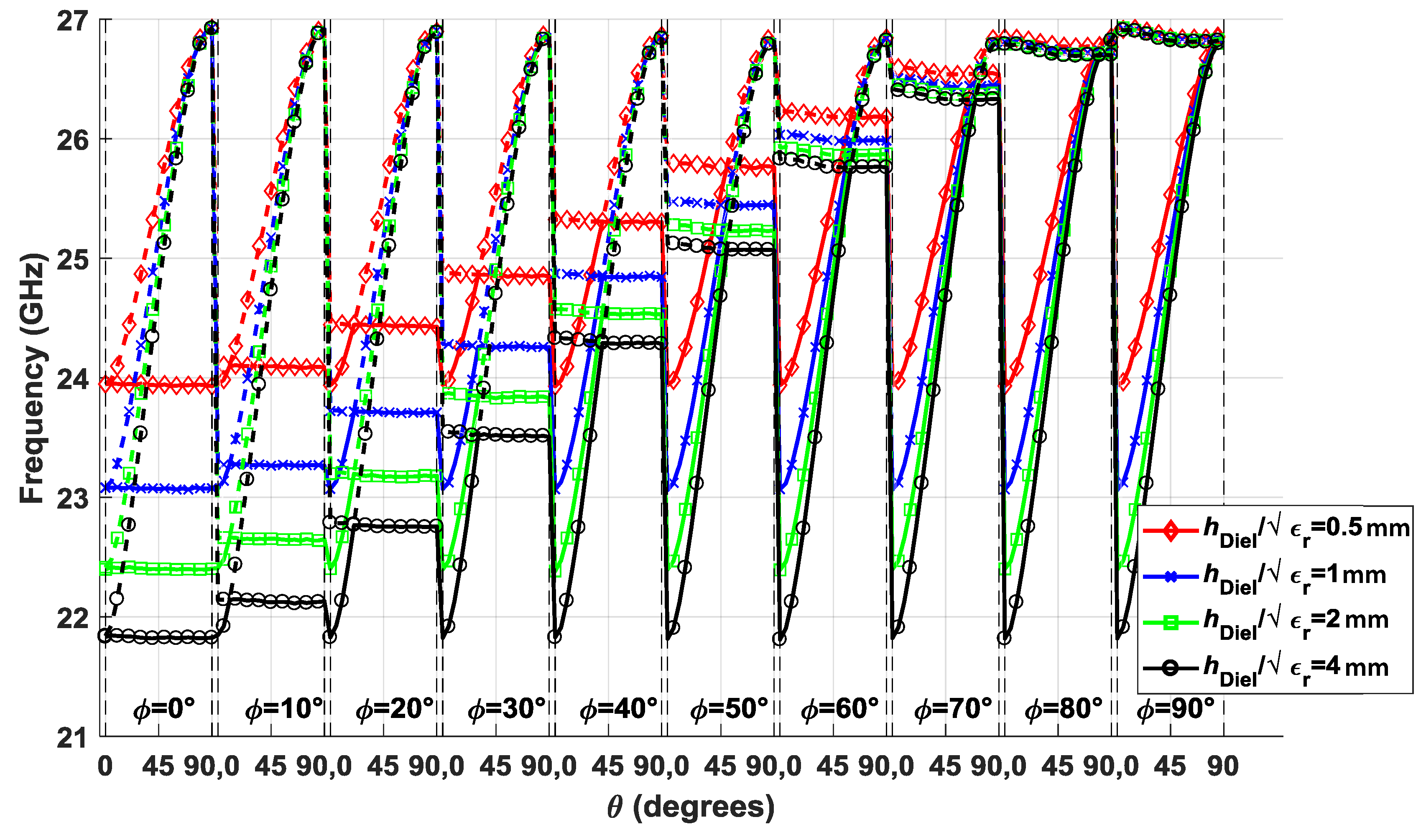
Another alternative to break the symmetry lies in the φ and θ angles at which the ellipses are oriented. Figure 5 depicts the stop-band behavior at a θ angle from 0° to 90° for φ values that also range from 0° to 90° in steps of 10°. In order to have a perspective of the effect of all the parameters of the structure, Figure 5 includes the results for various values of the thickness of the dielectric substrate normalized to the square root of its dielectric constant, hDiel/ (εr = 3). It can be observed that the curves cross each other when φ and θ are equal, which happens in cases where glide symmetry exists. Therefore, the stop-band opens for θ values that differ more from φ. The curves have a sinusoid shape associated with the rotation of the ellipses, for which only a half of the period is represented, since a similar behavior is expected in the other half (θ values from 90° to 180°). Regarding the thickness of the dielectric substrate, Figure 5 shows how the width of the stop-band increases for greater thicknesses, but this effect tends to saturate from a certain thickness. This is because the mode that penetrates the ellipses into the dielectric is an evanescent mode. Thus, when the thickness is small, the mode does not have enough space to be attenuated; however, for thicknesses greater than a certain threshold, the mode is attenuated enough so that it is not affected by an increase in thickness.
It should be noted that the points corresponding to cases with glide symmetry, where the stop-band closes, rise in frequency from the configuration φ = θ = 0° to the configuration φ = θ = 90°. This is equivalent to the reduction of the equivalent refractive index. This is due to the way in which the modes are coupled through the elliptical slots, which depends on their orientation perpendicular or parallel to the direction of propagation. The coupling of a transverse electromagnetic (TEM) mode is minimal in a slot oriented in the direction of propagation (φ = θ = 90°), but it is maximum if oriented perpendicularly (φ = θ = 0°). Therefore, the effect of dielectric substrate is lower in the first case producing a lower equivalent refractive index.
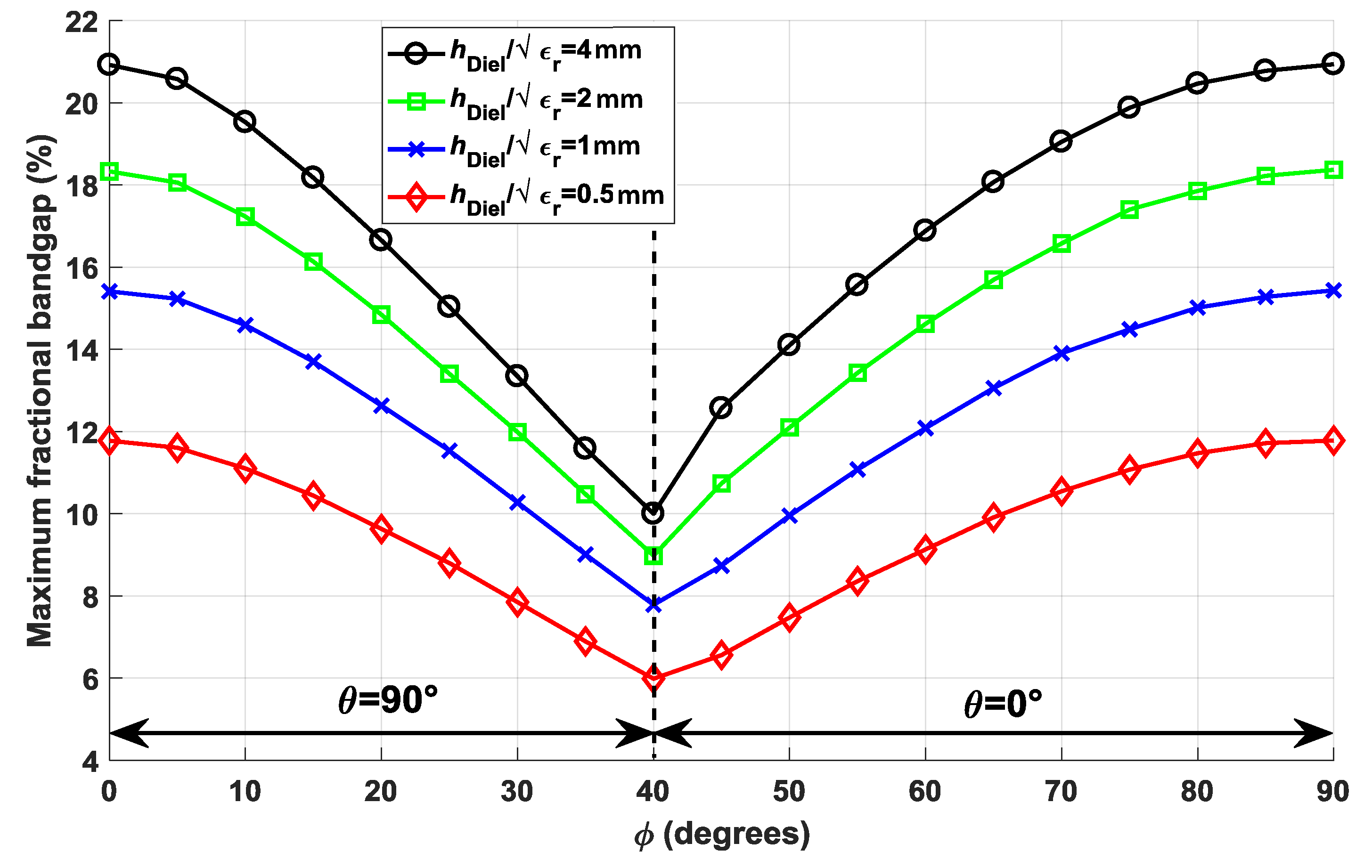
For clarity, the widest stop-band cases are selected for each φ value and represented in Figure 6 as a fractional stop-band. Wider stop-band structures have a θ value of 0° for φ values less than 40°, and 90° for φ values greater than 40°. Of all the cases presented, the maximum stop-band is given when φ = 0° and θ = 90° or φ = 90° and θ = 0°, which correspond to equivalent structures. In these cases, the width of the stop-band is about twice as wide as for φ = 40°. In Figure 6, we have a better visualization of the effect of dielectric thickness on the stop-band width. The thickness of the dielectric is doubled in each curve, but the increase in the width of stop-band is progressively reduced.
2.4. Stop-Band Frequency Shifting and Semi-Minor vs. Semi-Major Axis Relationship
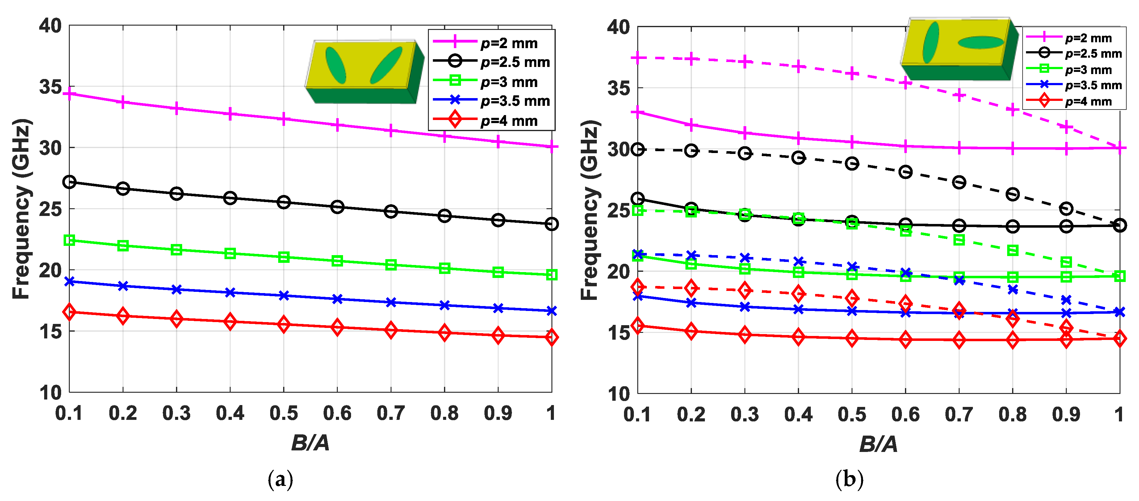
The last parametric study carried out in this work relates to the period of the structure with stop-band frequency displacement. Different values of period p were taken with the corresponding scaling of the ellipse dimensions to preserve the percentage of area occupied by the ellipses in the unit cell. The parameters of the reference structure for this stop-band study are as follows: hAir = 0.3 mm, hDiel = 1.52 mm, A1 = A2 = 2.5∙(p/2.75) mm, and d = 0 mm. A parametric sweep of the B1 and B2 values was also included in the study, so that the ratio of the semi-minor and semi-major axes B/A (B = B1 = B2; A = A1 = A2) of the ellipses varied from 0.1 to 1. The results are shown in Figure 7a,b. Figure 7a contains the dispersion diagram value at β(2p)/π = 1 of a structure with glide symmetry (φ = 30°, θ = 30°). The analysis on a broken-symmetry structure (φ = 0°, θ = 90°) is depicted in Figure 7b.
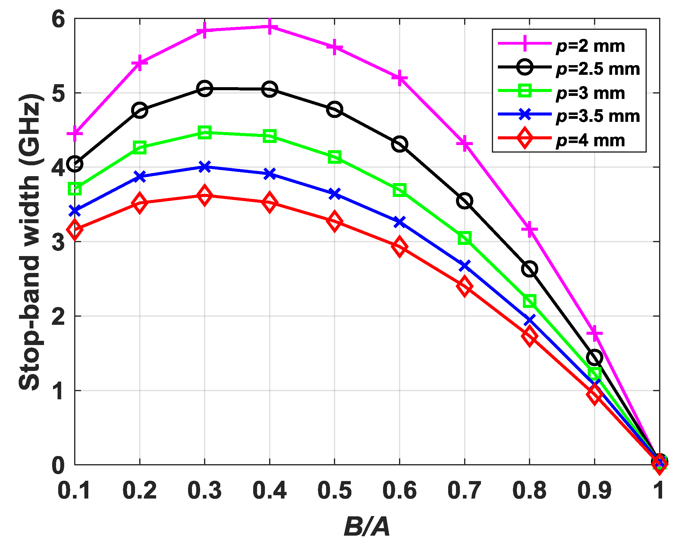
It is characteristic of periodic structures that the frequency behavior is inversely proportional to its period. Thus, in Figure 7, it is observed that the modes move downward in frequency with the inverse of p. In the glide-symmetric configuration, there is no stop-band; thus, in Figure 7a, only one curve is represented for each periodicity value p. It is interesting to note that, when the B/A value is higher, the frequency of the modes decreases, i.e., the refractive index increases. This is because the interaction of the electromagnetic fields with the dielectric material increases as a result of the reduction of the metallic surface. With respect to the non-glide configuration of Figure 7b, both the curve for the starting frequency (solid) and the curve for the ending frequency (dashed) of the stop-band are represented. The pattern is similar to the behavior of the glide configuration with the increase of the B/A value. However, there is a variation in the width of the stop-band that reaches its minimum when B/A = 1, in which we recover the symmetry and the stop-band disappears. Figure 8 represents the width of the stop-band obtained in each of the p values represented in Figure 7b. It is clearly observed that the maximum width of the stop-band is achieved for B/A values ranging between 0.3 and 0.4.
2.5. Regeneration of the Glide Symmetry
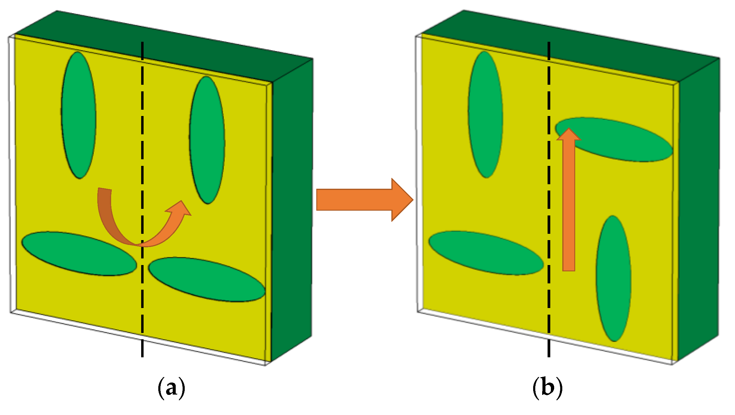
An interesting property of the structures analyzed in this work is the regeneration of glide symmetry from a structure with broken symmetry. The procedure consists of applying the symmetry again on the non-glide unit cell using one of the lateral edges as a symmetry axis. The procedure is shown in Figure 9, where the original unit cell is reflected and translated a distance p in the direction of propagation. Of special interest is the case in which the unit cell with broken symmetry has mirror symmetry, i.e., it is identical to the reflected unit cell considering the center in the y-direction as the axis of symmetry. This particularity allows to break and regenerate the symmetry only by displacing a column of the unit cell at periodicity p. In periodic prototypes with several unit cells, it implies the capacity to design reconfigurable structures based on the relative displacement of alternated columns in the direction of propagation.
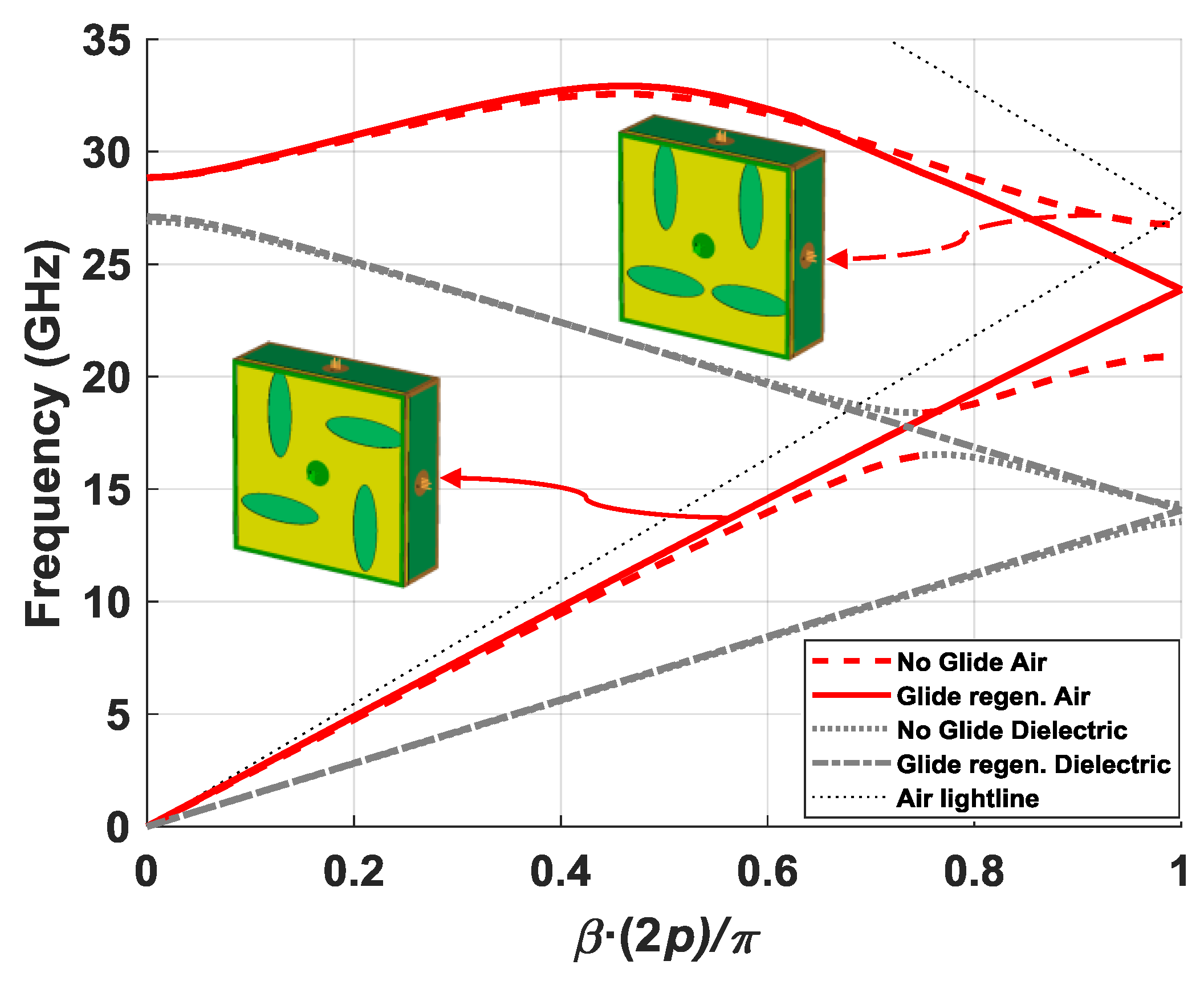
Figure 10 depicts a comparison of the dispersion diagrams obtained with the unit cells of Figure 9a,b. The main stop-band present for β(2p)/π = 1 in the non-glide unit cell, from 20.92 GHz to 26.76 GHz, closes completely by regenerating the symmetry. Another interesting effect on non-glide structures is the appearance of an additional stop-band produced by the merging of the forward mode in air with the reverse mode in the dielectric. In the example shown in Figure 10, this occurs for values around β(2p)/π = 0.75. This type of stop-band was explained in Reference [31] as a complex mode that propagates in the structure. This additional stop-band is also completely closed in the glide configuration.
2.6. Materials and Instrumentation
In order to carry out an experimental demonstration of the phenomena described in this section, different devices were used for both the manufacture and the measurement of prototypes. The manufacture of the ellipses on the substrate was carried out with an LPKF ProtoLaser S4 with the dielectric material RO4350B (εr = 3.66; tan(δ) = 0.0035 @10GHz). The necessary aluminum parts were machined in an external company. Twenty 2.92-mm coaxial connectors with a core diameter of 0.3 mm and length of 7 mm were chosen for the connections. The calibration kit used was the 85056K HP/Agilent. The measurements were made using two 2.92-mm low-phase-error coaxial cables minibend KR-6, and eight loads Anritsu K210. Finally, the vector network analyzer used was the Agilent 8722ES model.
3. Results
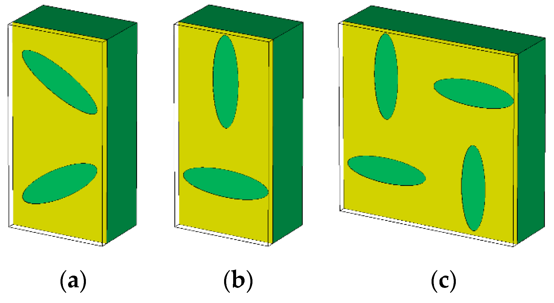
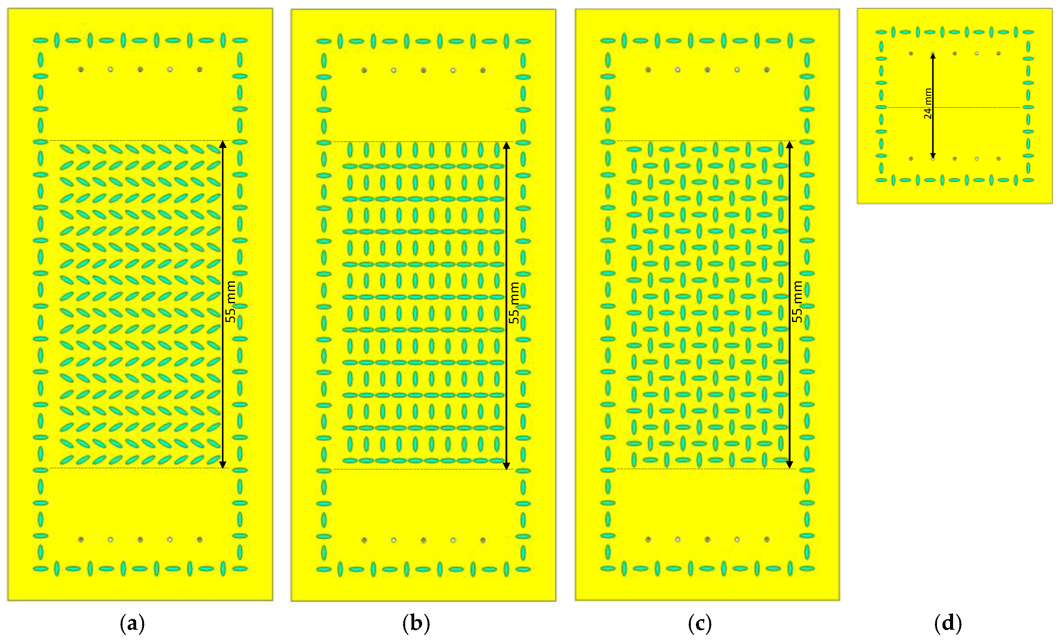
Four designs were made for the experimental demonstration. In three of them, we used the unit cells shown in Figure 11, which corresponded to the glide configuration (Figure 10), the non-glide configuration (Figure 11b), and the configuration with regenerated glide symmetry from a non-glide configuration (Figure 11c). The parameters chosen for the designs were εr = 3.66, hAir = 0.2 mm, hDiel = 1.52 mm, p = 2.75 mm, A1 = A2 = 2.5 mm, B1 = B2 = 0.75 mm, and d = 0 mm. The only values that were different were φ and θ, taking φ = θ = 30° for the glide configuration and φ = 0°, θ = 90° for the non-glide and regenerated configurations. The glide (Figure 12a) and non-glide (Figure 12b) designs contained 10 × 10 unit cells, whereas the design with regenerated symmetry (Figure 12c) contained only 5 × 10 unit cells due to the unit cell being twice as wide. The fourth design (Figure 12d) was a supporting structure that acted as a “thru” and that was used to make phase corrections in the measurements of the other three designs. The prototypes were excited by 10 coaxial connections, five on each side, to create a plane wave that emulated the boundary conditions used in the analyzed unit cells. It should be noted that we added a non-glide frame of ellipses around the four designs to prevent the propagation of spurious modes between the metal surface of the dielectric substrate and the aluminum casing that shielded these designs. As we can observe in Figure 12, the total length of the surface with ellipses was 55 mm (each unit cell was 5.5 mm in length), but the distance between the coaxial connectors and the ellipses was 24 mm in total. This is the separation that should exist between coaxial inputs and outputs of the “thru” for a correct post processing of the measurements.
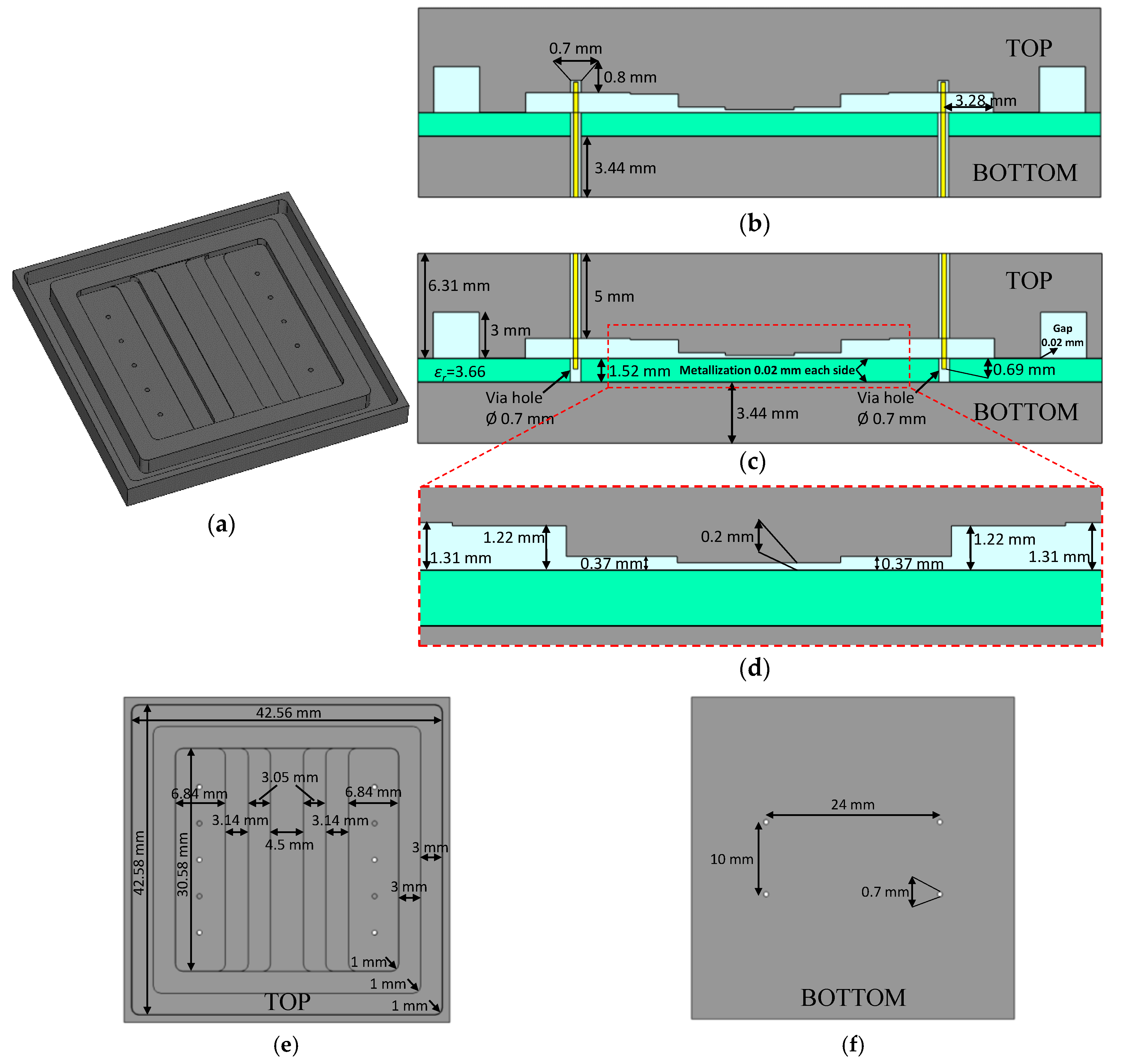
Two metal casings, one top and one bottom, covered the dielectric sheet. Ten coaxial connectors were inserted in these casings, six in the top casing and four in the bottom casing. In this way, the excitation at the input through five coaxial probes was achieved by alternating the up–down orientation of the connectors, as can be seen in the Figure 13. By introducing three probes from the top and two from the bottom, it is possible to achieve a separation between contiguous probes of 5 mm, which coincided with half a wavelength in free space at 30 GHz. This ensured a good plane wave across the desired frequency range, between 20 and 30 GHz. Since the base size of the coaxial connectors was 9.5 mm, it was impossible to achieve this separation by inserting the probes on one side only. Therefore, the purpose of these metal casings was threefold. First of all, the 2.92-mm coaxial connectors could be screwed on. Secondly, the internal shape of these casings provided an acceptable matching of the complete prototype between 20 and 30 GHz, as the phenomenon to be demonstrated occurred between these frequencies. Finally, the thickness of each casing (top and bottom) was such that the phase difference between the external surface and the inner surface was the same to ensure that all probes excited the structure in phase. For this, both the thickness of the dielectric and the metallization of both sides of the dielectric were taken into account. All dimensions of the metal casings are shown in detail in Figure 13. The internal structure of the top casing is shown in Figure 13a. This part corresponds to the design of the “thru”; thus, its length was smaller than for the other designs. In particular, this casing increased its length by an additional 55 mm while keeping the 0.2-mm gap in the center of the piece. There was a staggered shape from the input and output with the five holes for the coaxial probes to the central area with the gap of 0.2 mm. In the design, a 3-mm corrugation was introduced along the entire edge, which corresponded to approximately a quarter wavelength at the central frequency. This allowed the short to be transformed into open and again into short-circuit in the internal boundary of the casing, ensuring good electrical isolation of the fields. Figure 13b represents a lateral cut of the complete “thru” design where the coaxial probes entered from the bottom side. Similarly, Figure 13c shows another lateral cut in which the coaxial probes penetrated from the top side. All holes in the dielectric substrate with a diameter of 0.7 mm were metallized to preserve the coaxial structure when the probes were introduced through them. For a better visualization, Figure 13d includes a detailed image of the central zone of Figure 13b,c. Finally, Figure 13e,f present the details of the inner sides of the top and bottom part of the casing. All dimensional values required in the design of the casing are given in Figure 13b–f.
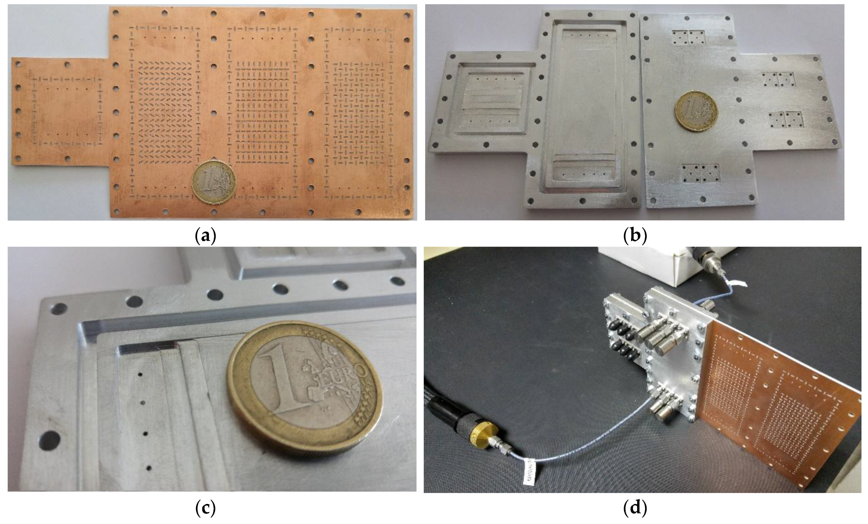
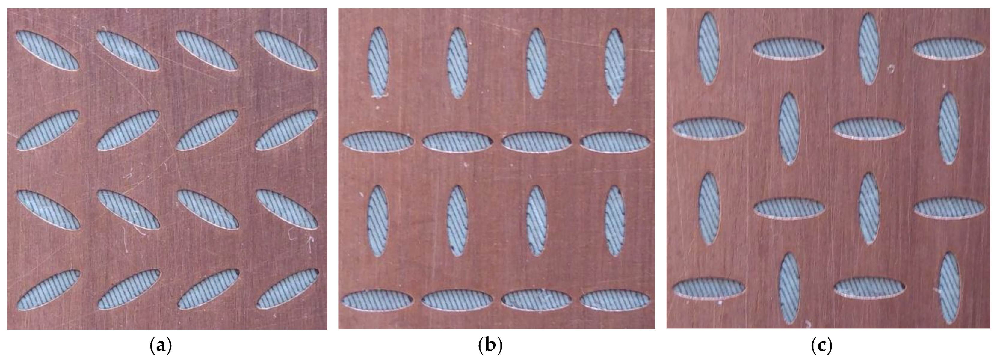
The images of the manufactured prototype are shown in Figure 14a–d. To reduce manufacturing costs, the four designs of Figure 12a–d were implemented on a single piece of dielectric substrate (Figure 14a). In addition, instead of manufacturing a complete metal casing covering the entire prototype in Figure 13a, a single casing was built with the short section for the thru and a long section for the glide (Figure 12a), non-glide (Figure 12b), and regenerated glide (Figure 12c) designs. This allowed a considerable reduction of the manufacturing cost, as the long section of the metal casing was identical in all three cases. This reduced casing consisted of the top and bottom parts, as shown in Figure 14b. Figure 14c shows a detailed photo of the stepped transition and Figure 14d depicts the final assembly in the measurement process with the cables and loads connected. For the measurement of the long designs, we moved the casing to the position of each one. Detailed images of the three ellipse configurations can be found in Figure 15: glide (Figure 15a), non-glide (Figure 15b), and regenerated glide (Figure 15c).
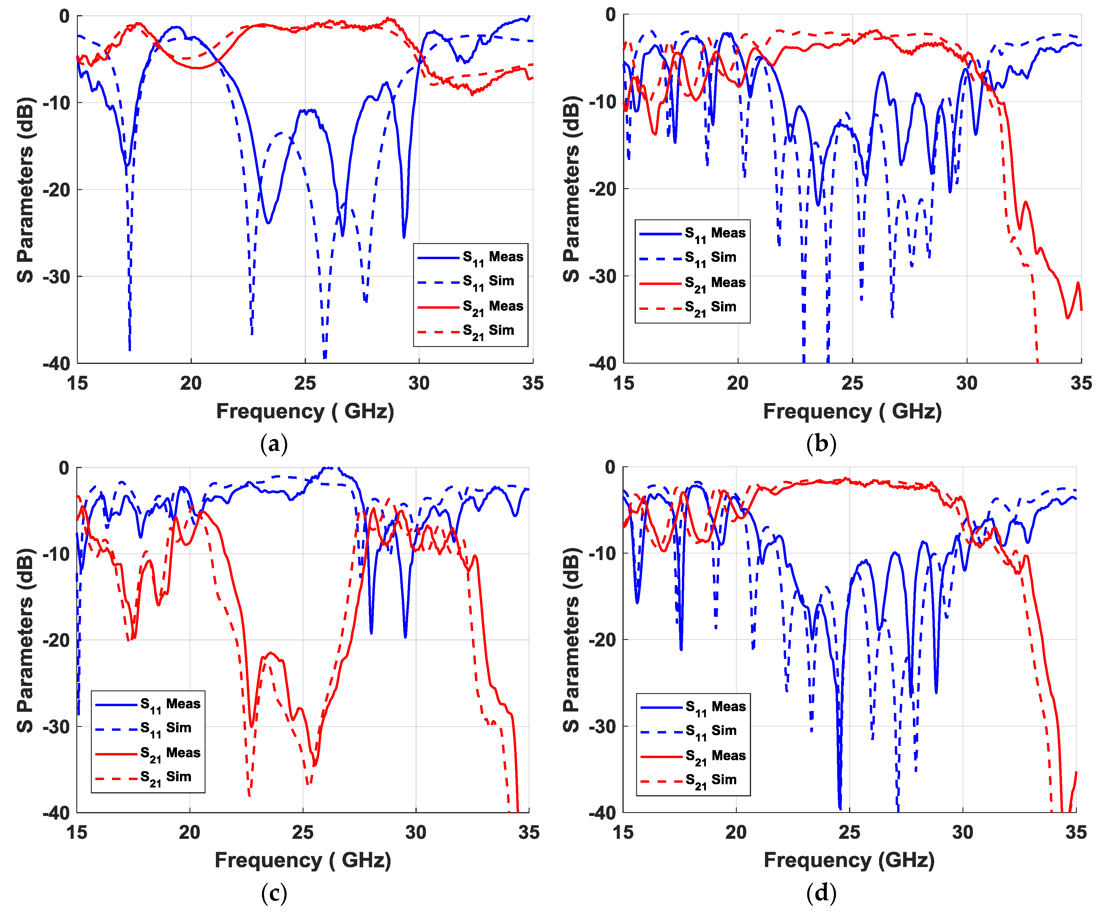
The measurement process was critical, requiring at least 35 measurements for each of the designs. Therefore, all connections had to be very stable to ensure that the conditions were the same in all 35 measurements. The results obtained from these 35 measurements were properly processed to combine the individual S parameters of each port in reflection and transmission parameters of an equivalent simultaneous excitation at the five input ports. This process was applied to the four designs, and the results obtained are represented in Figure 16, together with the results of the simulations. Figure 16a represents the results of the “thru” section, Figure 16b represents the results of the glide configuration section, Figure 16c represents the results of the non-glide section, and Figure 16d represents the results of the regenerated glide-symmetric design. The simulations were carried out including the losses in the dielectric (tan(δ) = 0.0035) and in the conductors (copper and aluminum). The results obtained fit very well with the simulations, with the exception of a small upward shift in frequency of approximately 0.5 GHz for all cases. The appearance of a band with an attenuation greater than 20 dB between 22.5 and 27.5 GHz was observed in the non-glide prototype (Figure 16c) with respect to the glide prototype (Figure 16b), whose effect was eliminated by regenerating the symmetry (Figure 16d). As indicated in Figure 10, an additional stop-band can be found at frequencies around 17.5 GHz in the non-glide case. The effect of this secondary stop-band was lower with an attenuation level between 15 and 20 dB, but it was present in the measurement due to the merging of the forward mode in the air and the backward mode in the dielectric. Finally, the appearance of a third stop-band in the three cases studied around 35 GHz was also of interest, which was produced again by the fusion of forward and backward modes in air and dielectric.
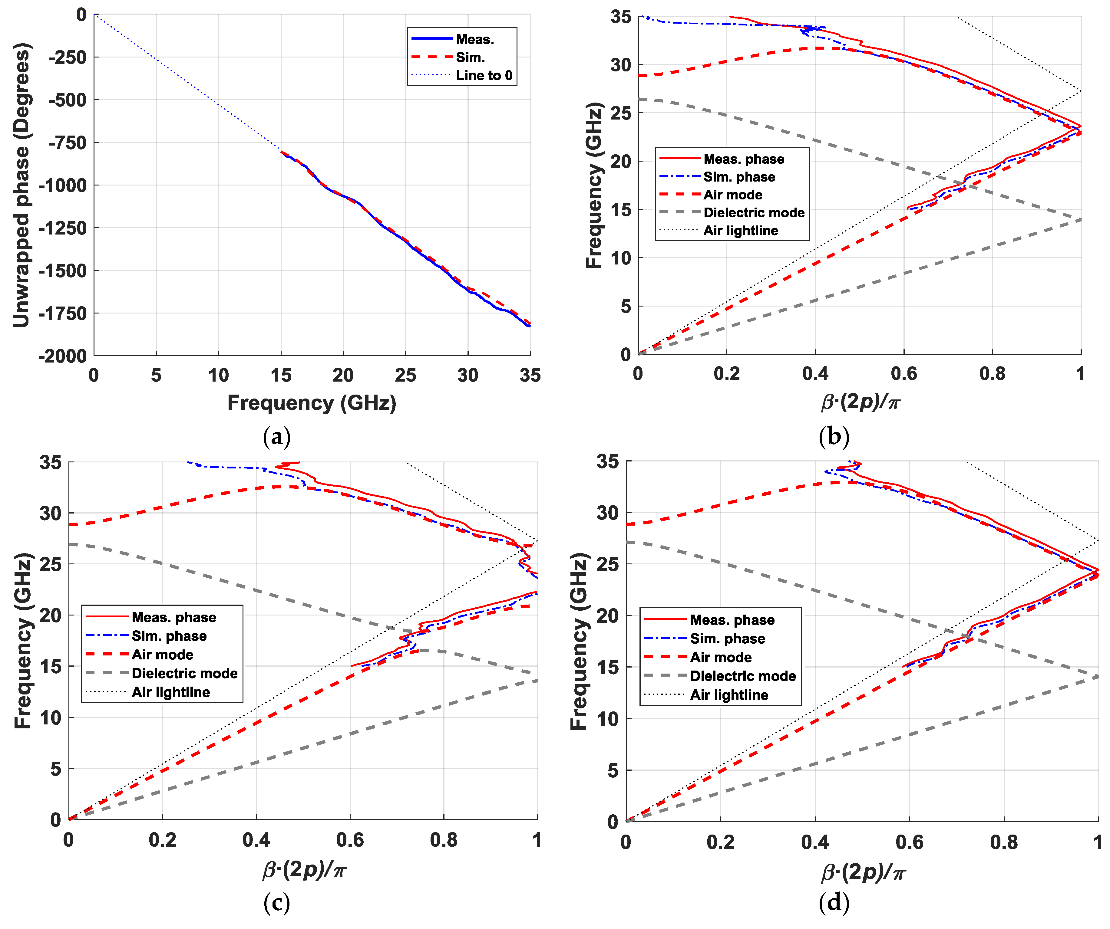
Of equal interest was the effect of these periodic elliptical structures on the phase. These results are depicted in Figure 17. For this study, the phase difference introduced by the “thru” section, represented in Figure 17a, was used as a reference. The first step was to eliminate the phase shift introduced by the “thru” section from the measured phase of the elliptical configurations. With this, we obtained the phase difference produced only by the 55-mm section with ellipses (10 unit cells). These results are represented in Figure 17b–d, applying a normalization in the phase with the factor β(2p)/π. As with the magnitude values, the measured phase values represented in the dispersion diagrams in Figure 17b,c coincided very well with the dispersion diagrams obtained from the unit-cell analysis. The 0.5-GHz upward deviation in frequency appeared again, but the shape exactly fit the results obtained in simulation. In addition to the measurement result, the graphs also included the result obtained from the full wave simulation of the S parameters of the complete designs, which matched better than the dispersion diagrams of the unit cells. In the glide (Figure 17b) and regenerated glide (Figure 17d) cases, a non-dispersive behavior up to 30 GHz was observed. The measured curve was closer to the light line in the regenerated glide configuration than in the original glide configuration, reaching the normalized value of 1 at 24.4 GHz in the first case and at 23.6 GHz in the second case (light line at 27.3 GHz). This means that there was a higher refractive index in the original configuration, which could be modified by varying the parameters of the unit cell. Of special interest was the dispersion diagram measured for the non-glide prototype (Figure 17c), in which the two stop-bands produced around 17.5 GHz and from 22 GHz to 27 GHz were clearly observed. In the range between these two stop-bands (18 to 22 GHz), there was a considerably higher refraction coefficient than in the glide configurations, which could be used to implement a structure with a higher phase-shifting capacity.
Figure 18 shows a comparison of the behavior of the electric field within the air gap, more precisely in a cut in the middle of the air gap (0.1 mm). The frequencies were conveniently selected to show the most interesting phenomena found in these structures: propagation at frequencies below the appearance of stop-bands (15 GHz), the maximum attenuation of the field found in the secondary stop-band (17.36 GHz), propagation between the two stop-bands (20.22 GHz), the maximum attenuation in the fundamental stop-band (25.28 GHz), propagation at a frequency above the two stop bands (28.86 GHz), and attenuation in the third stop band (35 GHz). The fields propagated homogeneously in the two glide configurations except in the capture at 35 GHz where a stop-band was present in all cases. For the non-glide prototype, the level of the electric field progressively decayed along the structure for the frequencies contained in the stop-bands, especially in the fundamental stop-band (25.28 GHz), which was exhaustively studied throughout this paper.
4. Discussion
This work introduced a new type of glide symmetry based on a single-plane metal structure. The usefulness of these structures lies in generating stop-bands with different levels of attenuation and a variety of refraction coefficients in a simple and easy implementation. This functionality was demonstrated with the analysis of dispersion diagrams and simulation and measurement of the S parameters of the manufactured prototypes. Our parametric study highlights the tremendous number of different configurations that this technology offers to produce stop-bands with different bandwidths at various frequencies, as well as to generate equivalent refractive indexes. Our experimental results showed a stop-band with a bandwidth of 5 GHz centered at the frequency of 25 GHz (20% fractional bandwidth) with an attenuation of 5.5 dB/cm for the non-glide configuration. In the measured glide and regenerated glide cases, a wideband propagation with refractive indexes of 1.12 and 1.16 was obtained, with a possibility to reach values higher than 1.3 with other configurations. The implementation was done using ellipses with a certain orientation on the metallic face of a dielectric substrate. On them, a smooth metal plate was placed at a given distance, providing a gap of air through which the propagation of the electromagnetic fields took place. Unlike previous glide-symmetric structures described in the literature, the alignment of the surface with ellipses and the upper metal plate is not a problem when manufacturing a prototype based on this technology, since a misalignment does not produce any rupture of the symmetry in this case. This is of particular interest for the design and manufacture of Luneburg lenses like the one developed in Reference [26], as it would reduce the manufacturing complexity. The Luneburg lens presented in Reference [26] was implemented by means of two opposing metal parts in which a glide-symmetric holey structure was machined. If the alignment of these two plates is not good enough, ruptures of symmetry may appear between the upper and lower plates, resulting in small stop-bands through the structure. The application of glide symmetry in a single plane prevents the occurrence of this problem. Although we demonstrated in this work that the rupture of the symmetry in the plane of the ellipses generates a stop-band with an attenuation of approximately 30 dB in 55 mm of surface, there are works that demonstrate that the glide-symmetric holey structures in two metallic surfaces provide a greater attenuation per unit length. In particular, the EGB achieved in Reference [23] provided 3.5 times more propagation blockage. This work only studied the attenuation in a particular configuration of ellipses to demonstrate the appearance of stop-bands; thus, further investigation with other configurations is required. The main function of the dielectric material used in the designs of this work is to act as a support for the glide-symmetric ellipses. Future lines of research focused on this type of structures can be based on the substitution of the dielectric substrate by a thin sheet of metal suspended in air with the pattern of ellipses. Since it was demonstrated that it is possible to regenerate glide symmetry from a specific non-glide configuration, the use of thin metal plates instead of dielectric material allows the possibility of breaking and regenerating symmetry by displacing alternate rows of ellipses at a distance equal to the periodicity p (see Figure 10). Another possibility is to replace the dielectric material with an anisotropic material such as liquid crystal [28], whose effective dielectric constant in the direction of propagation can be modified by applying a voltage between the parallel metal plates containing it [32]. This property would make it possible to electrically control the appearance of stop-bands and refractive index. Therefore, these structures offer the possibility of developing both mechanically and electrically reconfigurable devices.
Author Contributions
Conceptualization, O.Q.-T.; methodology, A.T.-D.; software, A.T.-D.; validation, A.T.-D.; formal analysis, A.T.-D.; investigation, A.T.-D.; resources, J.-M.F.-G.; data curation, A.T.-D.; writing—original draft preparation, A.T.-D.; writing—review and editing, A.T.-D.; visualization, A.T.-D.; supervision, J.-M.F.-G. and O.Q.-T.; project administration, J.-M.F.-G.; funding acquisition, J.-M.F.-G.
Funding
The authors would like to acknowledge the Spanish Government, Ministry of Economy, National Program of Research, Development, and Innovation for the support of this publication in the projects ENABLING-5G “Enabling innovative radio technologies for 5G networks” (project number TEC2014-55735-C3-1-R), FUTURE-RADIO "Radio systems and technologies for high capacity terrestrial and satellite communications in an hyperconnected world" (project number TEC2017-85529-C3-1-R), and the Madrid Regional Government under the project SPADERADAR “Space Debris Radar” (S2013/ICE-3000).
Acknowledgments
Simulations done in this work were performed using CST Microwave Studio Suite 2018 under a cooperation agreement with Computer Simulation Technology (CST).
Conflicts of Interest
The authors declare no conflict of interest. The funders had no role in the design of the study; in the collection, analyses, or interpretation of data; in the writing of the manuscript, or in the decision to publish the results.
References
- Dahlberg, O.; Mitchell-Thomas, R.C.; Quevedo-Teruel, O. Reducing the dispersion of periodic structures with twist and polar glide symmetries. Sci. Rep. 2017, 7, 10136. [Google Scholar] [CrossRef] [PubMed]
- Ghasemifard, F.; Norgren, M.; Quevedo-Teruel, O. Twist and polar glide symmetries: An additional degree of freedom to control the propagation characteristics of periodic structures. Sci. Rep. 2018, 8, 11266. [Google Scholar] [CrossRef]
- Chen, Q.; Ghasemifard, F.; Valerio, G.; Quevedo-Teruel, O. Modeling and dispersion analysis of coaxial lines with higher symmetries. IEEE Trans. Microw. Theory Tech. 2018, 66, 4338–4345. [Google Scholar] [CrossRef]
- Quevedo-Teruel, O.; Dahlberg, O.; Valerio, G. Propagation in waveguides with transversal twist-symmetric holey metallic plates. IEEE Microw. Wirel. Compon. Lett. 2018, 28, 858–860. [Google Scholar] [CrossRef]
- Palomares-Caballero, A.; Padilla, P.; Alex-Amor, A.; Valenzuela-Valdes, J.; Quevedo-Teruel, O. Twist and glide symmetries for helix antenna design and miniaturization. Symmetry 2019, 11, 349. [Google Scholar] [CrossRef]
- Crepeau, P.J.; McIsaac, P.R. Consequences of symmetry in periodic structures. Proc. IEEE 1964, 52, 33–43. [Google Scholar] [CrossRef]
- Hessel, A.; Chen, M.H.R.; Li, C.M.; Oliner, A.A. Propagation in periodically loaded waveguides with higher symmetries. Proc. IEEE 1973, 61, 183–195. [Google Scholar] [CrossRef]
- Kieburtz, R.; Impagliazzo, J. Multimode propagation on radiating traveling-wave structures with glide-symmetric excitation. IEEE Trans. Antennas Propag. 1970, 18, 3–7. [Google Scholar] [CrossRef]
- Quevedo-Teruel, O.; Ebrahimpouri, M.; Kehn, M.N.M. Ultrawideband Metasurface lenses based on off-shifted opposite layers. IEEE Antennas Wirel. Propag. Lett. 2016, 15, 484–487. [Google Scholar] [CrossRef]
- Ebrahimpouri, M.; Quevedo-Teruel, O.; Rajo-Iglesias, E. Design guidelines for gap waveguide technology based on glide-symmetric holey structures. IEEE Microw. Wirel. Compon. Lett. 2017, 27, 542–544. [Google Scholar] [CrossRef]
- Valerio, G.; Sipus, Z.; Grbic, A.; Quevedo-Teruel, O. Accurate equivalent-circuit descriptions of thin glide-symmetric corrugated metasurfaces. IEEE Trans. Antennas Propag. 2017, 65, 2695–2700. [Google Scholar] [CrossRef]
- Ghasemifard, F.; Norgren, M.; Quevedo-Teruel, O. Dispersion analysis of 2-D glide-symmetric corrugated metasurfaces using mode-matching technique. IEEE Microw. Wirel. Compon. Lett. 2018, 28, 1–3. [Google Scholar] [CrossRef]
- Valerio, G.; Ghasemifard, F.; Sipus, Z.; Quevedo-Teruel, O. Glide-symmetric all-metal holey metasurfaces for low-dispersive artificial materials: Modeling and properties. IEEE Trans. Microw. Theory Tech. 2018, 66, 3210–3223. [Google Scholar] [CrossRef]
- Ghasemifard, F.; Norgren, M.; Quevedo-Teruel, O.; Valerio, G. Analyzing glide-symmetric holey metasurfaces using a generalized floquet theorem. IEEE Access 2018, 6, 71743–71750. [Google Scholar] [CrossRef]
- Camacho, M.; Mitchell-Thomas, R.C.; Hibbins, A.P.; Sambles, J.R.; Quevedo-Teruel, O. Designer surface plasmon dispersion on a one-dimensional periodic slot metasurface with glide symmetry. Opt. Lett. 2017, 42, 3375–3378. [Google Scholar] [CrossRef]
- Camacho, M.; Mitchell-Thomas, R.C.; Hibbins, A.P.; Sambles, J.R.; Quevedo-Teruel, O. Mimicking glide symmetry dispersion with coupled slot metasurfaces. Appl. Phys. Lett. 2017, 111, 121603. [Google Scholar] [CrossRef]
- Padilla, P.; Herran, L.F.; Tamayo-Dominguez, A.; Valenzuela-Valdes, J.F.; Quevedo-Teruel, O. Glide symmetry to prevent the lowest stopband of printed corrugated transmission lines. IEEE Microw. Wirel. Compon. Lett. 2018, 28, 750–752. [Google Scholar] [CrossRef]
- Quesada, R.; Martín-Cano, D.; García-Vidal, F.J.; Bravo-Abad, J. Deep subwavelength negative-index waveguiding enabled by coupled conformal surface plasmons. Opt. Lett. 2014, 39, 2990–2993. [Google Scholar] [CrossRef]
- Cavallo, D.; Felita, C. Analytical formulas for artificial dielectrics with nonaligned layers. IEEE Trans. Antennas Propag. 2017, 65, 5303–5311. [Google Scholar] [CrossRef]
- Cavallo, D. Dissipation losses in artificial dielectric layers. IEEE Trans. Antennas Propag. 2018, 66, 7460–7465. [Google Scholar] [CrossRef]
- Chang, T.; Kim, J.U.; Kang, S.K.; Kim, H.; Kim, D.K.; Lee, Y.H.; Shin, J. Broadband giant-refractive-index material based on mesoscopic space-fillingcurves. Nat. Commun. 2016, 7, 12661. [Google Scholar] [CrossRef] [PubMed]
- Jia, D.; He, Y.; Ding, N.; Zhou, J.; Du, B.; Zhang, W. Beam-steering flat lens antenna based on multilayer gradient index metamaterials. IEEE Antennas Wirel. Propag. Lett. 2018, 17, 1510–1514. [Google Scholar] [CrossRef]
- Ebrahimpouri, M.; Rajo-Iglesias, M.; Sipus, Z.; Quevedo-Teruel, O. Cost-effective gap waveguide technology based on glide-symmetric holey EBG structures. IEEE Trans. Microw. Theory Tech. 2018, 66, 927–934. [Google Scholar] [CrossRef]
- Ebrahimpouri, M.; Algaba-Brazalez, A.; Manholm, L.; Quevedo-Teruel, O. Using glide-symmetric holes to reduce leakage between waveguide flanges. IEEE Microw. Wirel. Compon. Lett. 2018, 28, 473–475. [Google Scholar] [CrossRef]
- Rajo-Iglesias, E.; Ebrahimpouri, M.; Quevedo-Teruel, O. Wideband phase shifter in groove gap waveguide technology implemented with glide-symmetric holey EBG. IEEE Microw. Wirel. Compon. Lett. 2018, 28, 476–478. [Google Scholar] [CrossRef]
- Quevedo-Teruel, O.; Miao, J.; Mattsson, M.; Algaba-Brazalez, A.; Johansson, M.; Manholm, L. Glide-symmetric fully-metallic Luneburg lens for 5G communications at Ka-band. IEEE Antennas Wirel. Propag. Lett. 2018, 17, 1588–1592. [Google Scholar] [CrossRef]
- Quevedo-Teruel, O.; Ebrahimpouri, M.; Ghasemifard, F. Lens antennas for 5G communications systems. IEEE Commun. Mag. 2018, 56, 36–41. [Google Scholar] [CrossRef]
- Mueller, S.; Penirschke, A.; Damm, C.; Scheele, P.; Wittek, M.; Weil, C.; Jakoby, R. Broad-band microwave characterization of liquid crystals using a temperature-controlled coaxial transmission line. IEEE Trans. Microw. Theory Tech. 2005, 53, 1937–1945. [Google Scholar] [CrossRef]
- Mesa, F.; Rodríguez-Berral, R.; Medina, F. On the computation of the dispersion diagram of symmetric one-dimensionally periodic structures. Symmetry 2018, 10, 307. [Google Scholar] [CrossRef]
- Nosrati, M.; Daneshmand, M. Substrate Integrated Waveguide L-Shaped Iris for realization of transmission zero and evanescent-mode pole. IEEE Trans. Microw. Theory Tech. 2017, 65, 2310–2320. [Google Scholar] [CrossRef]
- Valerio, G.; Galli, A.; Wilton, D.R.; Jackson, D.R. An enhanced integral-equation formulation for accurate analysis of frequency-selective structures. Int. J. Microw. Wirel. Technol. 2012, 4, 365–372. [Google Scholar] [CrossRef]
- Alex-Amor, A.; Tamayo-Domínguez, A.; Palomares-Caballero, A.; Fernández-González, J.M.; Padilla, P.; Valenzuela-Valdés, J.; Palomares, A. Analytical approach of director tilting in nematic liquid crystals for electronically tunable devices. IEEE Access 2019, 7, 14883–14893. [Google Scholar] [CrossRef]
Figure 1.
Unit cell of the proposed structure and parametrization. View in perspective (a), and top view without the top metal plate (b).
Figure 1.
Unit cell of the proposed structure and parametrization. View in perspective (a), and top view without the top metal plate (b).

Figure 2.
Dispersion diagrams for two configurations of the unit cell: glide-symmetric (a) and non-glide-symmetric (b).
Figure 2.
Dispersion diagrams for two configurations of the unit cell: glide-symmetric (a) and non-glide-symmetric (b).

Figure 3.
Effect of the size of the second ellipse versus the first ellipse A2/A1 for different values of A1. The rest of the parameters are εr = 3, hAir = 0.3 mm, hDiel = 1.52 mm, p = 2.75 mm, B1/A1 = B2/A2 = 0.3, φ = θ = 30°, and d = 0 mm.
Figure 3.
Effect of the size of the second ellipse versus the first ellipse A2/A1 for different values of A1. The rest of the parameters are εr = 3, hAir = 0.3 mm, hDiel = 1.52 mm, p = 2.75 mm, B1/A1 = B2/A2 = 0.3, φ = θ = 30°, and d = 0 mm.

Figure 4.
Effect of the displacement d of the second ellipse toward the first ellipse for different values of the air gap thickness hAir/p. The rest of the parameters are εr = 3, hDiel = 1.52 mm, p = 2.75 mm, A1 = A2 = 2.5 mm, B1 = B2 = 0.75 mm, and φ = θ = 30°.
Figure 4.
Effect of the displacement d of the second ellipse toward the first ellipse for different values of the air gap thickness hAir/p. The rest of the parameters are εr = 3, hDiel = 1.52 mm, p = 2.75 mm, A1 = A2 = 2.5 mm, B1 = B2 = 0.75 mm, and φ = θ = 30°.

Figure 5.
Effect of the orientation φ and θ of each of the two ellipses for different values of the dielectric substrate thickness hDiel/. The rest of the parameters are εr = 3, hAir = 0.3 mm, p = 2.75 mm, A1 = A2 = 2.5 mm, B1 = B2 = 0.75 mm, and d = 0 mm.
Figure 5.
Effect of the orientation φ and θ of each of the two ellipses for different values of the dielectric substrate thickness hDiel/. The rest of the parameters are εr = 3, hAir = 0.3 mm, p = 2.75 mm, A1 = A2 = 2.5 mm, B1 = B2 = 0.75 mm, and d = 0 mm.

Figure 6.
Maximum fractional stop-band found for each value of φ in Figure 5 considering different substrate thicknesses.
Figure 6.
Maximum fractional stop-band found for each value of φ in Figure 5 considering different substrate thicknesses.

Figure 7.
Effect of the semi-minor vs. semi-major axis B/A relationship for different values of the period p: values for a glide-symmetric structure (a) and a non-glide structure (b). The rest of the parameters are hAir = 0.3 mm, A1 = A2 = 2.5∙(p/2.75) mm, and d = 0 mm.
Figure 7.
Effect of the semi-minor vs. semi-major axis B/A relationship for different values of the period p: values for a glide-symmetric structure (a) and a non-glide structure (b). The rest of the parameters are hAir = 0.3 mm, A1 = A2 = 2.5∙(p/2.75) mm, and d = 0 mm.

Figure 8.
Bandwidth of the stop-band for the non-glide configuration in Figure 7b as a function of B/A for different values of periodicity p.
Figure 8.
Bandwidth of the stop-band for the non-glide configuration in Figure 7b as a function of B/A for different values of periodicity p.

Figure 9.
The non-glide-symmetric structure in Figure 7b mirrored using a different symmetry axis (a); the new glide-symmetric structure (b) is obtained from (a) after applying a translation.
Figure 9.
The non-glide-symmetric structure in Figure 7b mirrored using a different symmetry axis (a); the new glide-symmetric structure (b) is obtained from (a) after applying a translation.

Figure 10.
Dispersion diagram of the structure in Figure 9b with regenerated symmetry compared to the original non-glide-symmetric structure in Figure 9a.

Figure 11.
Unit cells of the manufactured designs: glide-symmetric configuration (a), non-glide configuration (b), and regenerated glide configuration (c).
Figure 11.
Unit cells of the manufactured designs: glide-symmetric configuration (a), non-glide configuration (b), and regenerated glide configuration (c).

Figure 12.
Elliptic configurations of the final designs: glide configuration (a), non-glide configuration (b), regenerated glide configuration (c), and “thru” section (d).
Figure 12.
Elliptic configurations of the final designs: glide configuration (a), non-glide configuration (b), regenerated glide configuration (c), and “thru” section (d).

Figure 13.
Pieces of the metal casing for the “thru” section. Inner view of the top piece (a); cross-section with the probes entering from the bottom part (b); cross-section with the probes entering from the top part (c); detailed view of the stepped transition (d); details of the top piece (e); details of bottom pieces (f).

Figure 14.
Pictures of the manufactured prototypes and assembly. Dielectric substrate with the elliptic patterns (a); top and bottom parts of the casing (b); detail of the transition at the top part of the casing (c); final measurement assembly (d).
Figure 14.
Pictures of the manufactured prototypes and assembly. Dielectric substrate with the elliptic patterns (a); top and bottom parts of the casing (b); detail of the transition at the top part of the casing (c); final measurement assembly (d).

Figure 15.
Detailed pictures of the elliptic configurations: glide configuration (a), non-glide configuration (b), and regenerated glide configuration (c).
Figure 15.
Detailed pictures of the elliptic configurations: glide configuration (a), non-glide configuration (b), and regenerated glide configuration (c).

Figure 16.
Simulated and measured S parameters of the “thru” section (a), the glide configuration (b), the non-glide configuration (c), and the regenerated glide configuration (d).
Figure 16.
Simulated and measured S parameters of the “thru” section (a), the glide configuration (b), the non-glide configuration (c), and the regenerated glide configuration (d).

Figure 17.
Simulated and measured phases in transmission. Phase introduced by the “thru” section (a), and dispersion diagrams of the glide (b), non-glide (c), and regenerated glide (d) configurations.
Figure 17.
Simulated and measured phases in transmission. Phase introduced by the “thru” section (a), and dispersion diagrams of the glide (b), non-glide (c), and regenerated glide (d) configurations.

Figure 18.
Representations of the electric field inside the air gap of the simulated prototypes for the three configurations under study at given frequencies of interest.
Figure 18.
Representations of the electric field inside the air gap of the simulated prototypes for the three configurations under study at given frequencies of interest.

© 2019 by the authors. Licensee MDPI, Basel, Switzerland. This article is an open access article distributed under the terms and conditions of the Creative Commons Attribution (CC BY) license (http://creativecommons.org/licenses/by/4.0/).
Share and Cite
MDPI and ACS Style
Tamayo-Dominguez, A.; Fernandez-Gonzalez, J.-M.; Quevedo-Teruel, O. One-Plane Glide-Symmetric Holey Structures for Stop-Band and Refraction Index Reconfiguration. Symmetry 2019, 11, 495. https://0-doi-org.brum.beds.ac.uk/10.3390/sym11040495
AMA Style
Tamayo-Dominguez A, Fernandez-Gonzalez J-M, Quevedo-Teruel O. One-Plane Glide-Symmetric Holey Structures for Stop-Band and Refraction Index Reconfiguration. Symmetry. 2019; 11(4):495. https://0-doi-org.brum.beds.ac.uk/10.3390/sym11040495
Chicago/Turabian StyleTamayo-Dominguez, Adrian, Jose-Manuel Fernandez-Gonzalez, and Oscar Quevedo-Teruel. 2019. "One-Plane Glide-Symmetric Holey Structures for Stop-Band and Refraction Index Reconfiguration" Symmetry 11, no. 4: 495. https://0-doi-org.brum.beds.ac.uk/10.3390/sym11040495
Note that from the first issue of 2016, this journal uses article numbers instead of page numbers. See further details here.