Design Procedure of a Topologically Optimized Scooter Frame Part


1
Department of Machine Parts and Mechanisms, Faculty of Mechanical Engineering, VSB-Technical University of Ostrava, 708 33 Ostrava, Czech Republic
2
Department of Machining, Assembly and Engineering Metrology, Faculty of Mechanical Engineering, VSB-Technical University of Ostrava, 708 33 Ostrava, Czech Republic
*
Author to whom correspondence should be addressed.
Symmetry 2020, 12(5), 755; https://0-doi-org.brum.beds.ac.uk/10.3390/sym12050755
Submission received: 31 January 2020
/
Revised: 6 April 2020
/
Accepted: 8 April 2020
/
Published: 6 May 2020
(This article belongs to the Special Issue Symmetry in Mechanical Engineering Ⅱ)
Abstract
:This article describes the design procedure of a topologically optimized scooter frame part. It is the rear heel of the frame, one of the four main parts of a scooter made with stainless steel 3D printing. The first part of the article deals with the design area definition and the determination of load cases for topology calculation. The second part describes the process of the topology optimization itself and the creation of the volume body based on the calculation results. Finally, the final control using an FEM (Finite Element Method) analysis and optimization of created Computer-Aided Design (CAD) data is shown. Part of the article is also a review of partial iterations and resulting versions of the designed part. Symmetry was used to define boundary conditions, which led to computing time savings, as well as during the CAD model creation, where non-parametric surfaces were mirrored to shorten the design time.
1. Introduction
The development of additive technologies (3D printing) has grown considerably in the area of creative design and the modern technical approach to component design. Three-dimensional printing has changed the mindset of designers and engineers who can apply new technological design principles with regard to the technological production process and take advantage of the possibility of lightening parts designed especially for the automotive and aerospace industries.
A modern design approach allows designers to design components that have a so-called bionic shape [1]. This is created by free-form modelling in specialized CAD software. Compared to conventional technologies, it makes it possible to design parts that very often have surfaces which are mathematically difficult to define. In practice, such parts cannot be produced without simultaneous five-axis milling and in many cases, such as the production of hollow metal frames [2], 3D printing is necessary as they cannot be produced by another technology. Another typical example is lattice structures. They are designed to absorb impact energy [3,4], reduce vibration and noise, or serve as a thermal conductor. These parts cannot be manufactured in any other way than by 3D printing.
When we talk about bionic design, we mean shapes inspired by nature. The constructions may have a non-technical shape resembling biological structures, such as tree branch structures, the root system, skeletal shapes, or animal bodies [5,6]. Material is involved only where it is strictly necessary due to boundary conditions. Every designed model with bionic construction is thoroughly checked by an FEM analysis and specialized software is used for the calculation. The designer defines the material based on the design area and only where it fulfills its exclusive purpose in terms of mechanical properties. This process is called topological optimization, whose detailed procedure is presented later in this paper and is represented on a scooter foot model.
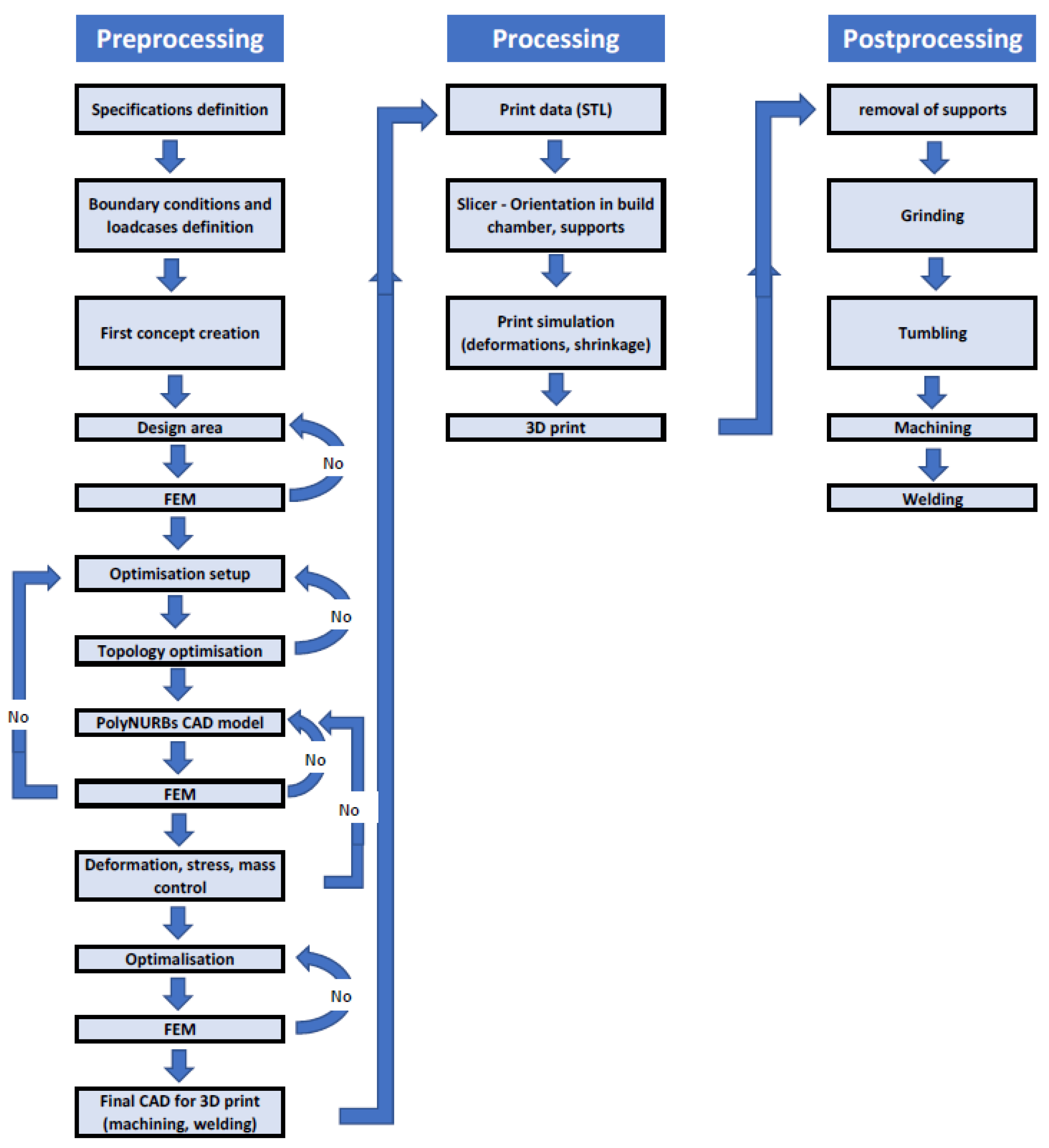
Within the additive manufacturing laboratory ProtoLab, which deals with 3D printing and CAD design, the topologically optimized scooter was designed and 3D printed. The aim was to design and develop a scooter frame that is topologically optimized with a bionic shape and made by additive manufacturing. Furthermore, the goal was to achieve weight reduction over conventional scooters. In Figure 1, the whole design process workflow is shown.
During the part’s design, two times symmetry was used. First, when boundary conditions were defined, the symmetry constraint was used. This boundary condition is used to create optimized shapes with nearly symmetric results. It also saves computing time, as only half of the optimization task is solved. Secondly, symmetry was used during CAD model creation, where non-parametric surfaces were mirrored to save the design time and to ensure the symmetry of the part.
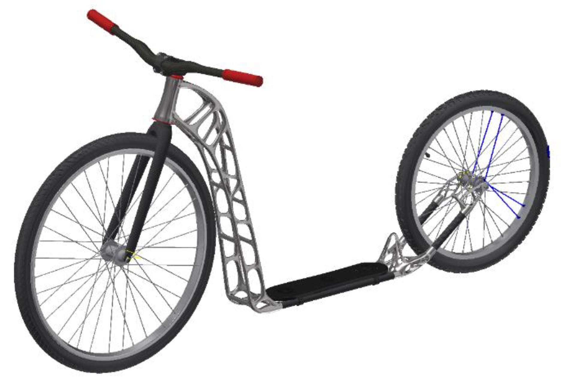
The result is a functional prototype of the scooter shown in Figure 2, which has a bionic frame printed with stainless steel. A 25% weight saving was achieved compared to conventional scooter frames while maintaining sufficient rigidity. The frame consists of 4 stainless steel elements and 4 carbon composite profiles joined together by gluing. Printed metal elements were post-processed by tumbling in ceramic elements to get a smooth appearance. The large front frame part was divided into 4 sub-parts before printing, with regards to the size of the building chamber. These parts were welded together afterwards using the TIG (tungsten inert gas) welding method.
The aim of this article was to show the optimization process on one of the frame parts. The rear heel of the frame was selected, which joins the profiles under the step and rear wheel fork profile. The paper deals with the design of load parameters, analysis settings and CAD model creation. Next, the subsequent manufacturing method of the part is described.
2. Materials and Methods
2.1. Design Variants
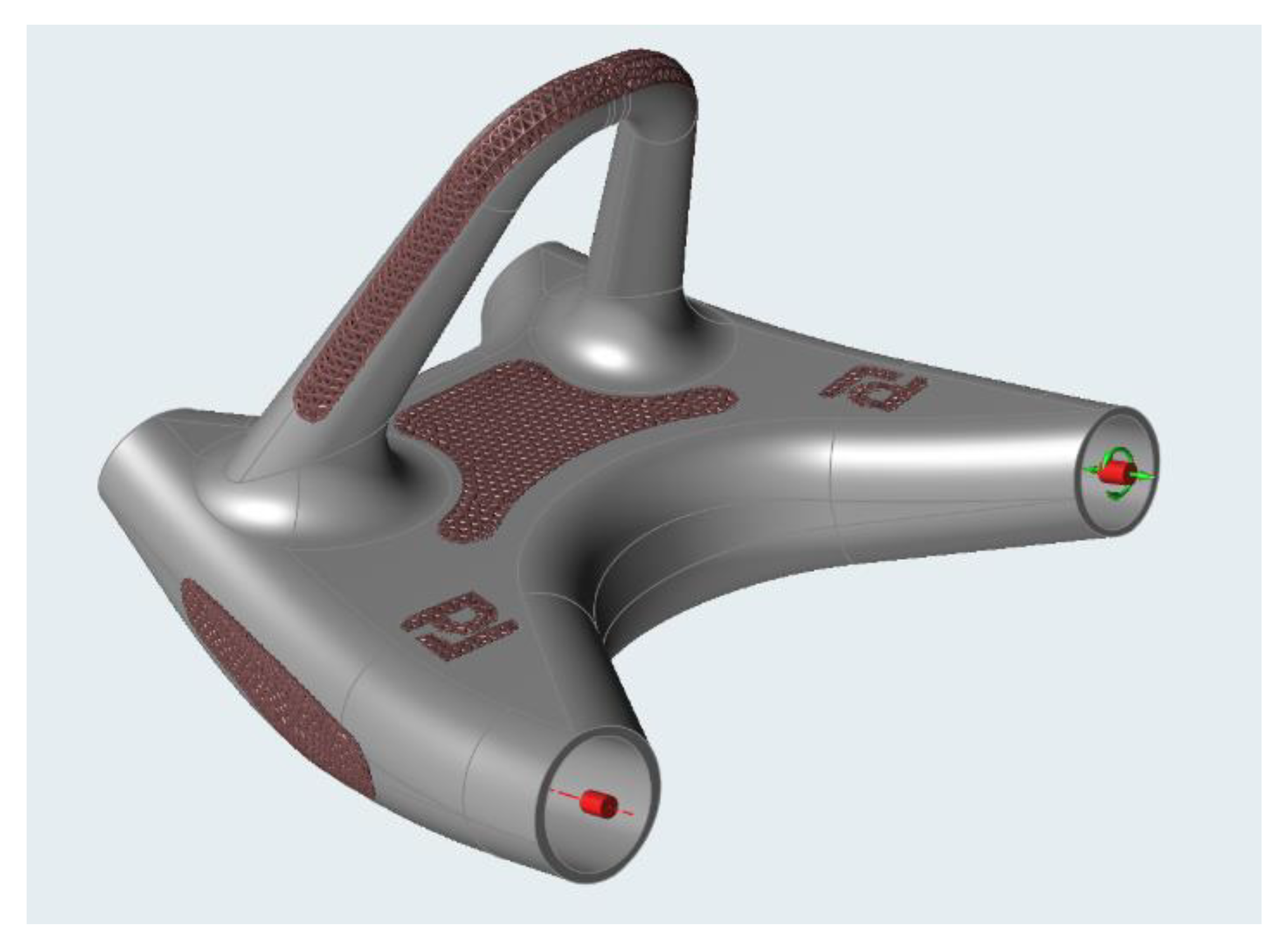
The design of the heel shape and appearance was based on the first design sketches of the whole scooter, so that its design matched the rest of the construction while meeting the necessary strength parameters. Two developmental variants of the heel were developed. The first is a hollow shell with an internal space filled with lattice structure. Internal lattice infill strengthens the structure with a minimal weight increase. As such, a tetrahedral lattice pattern was chosen [7]. There were also aesthetic viewports designed, through which the lattice structure inside can be seen (see Figure 3).
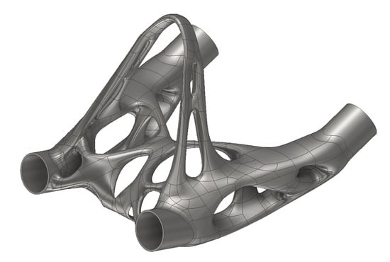
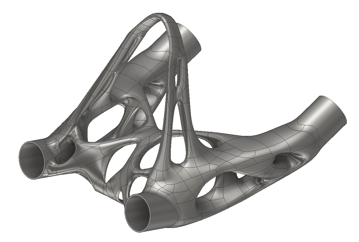
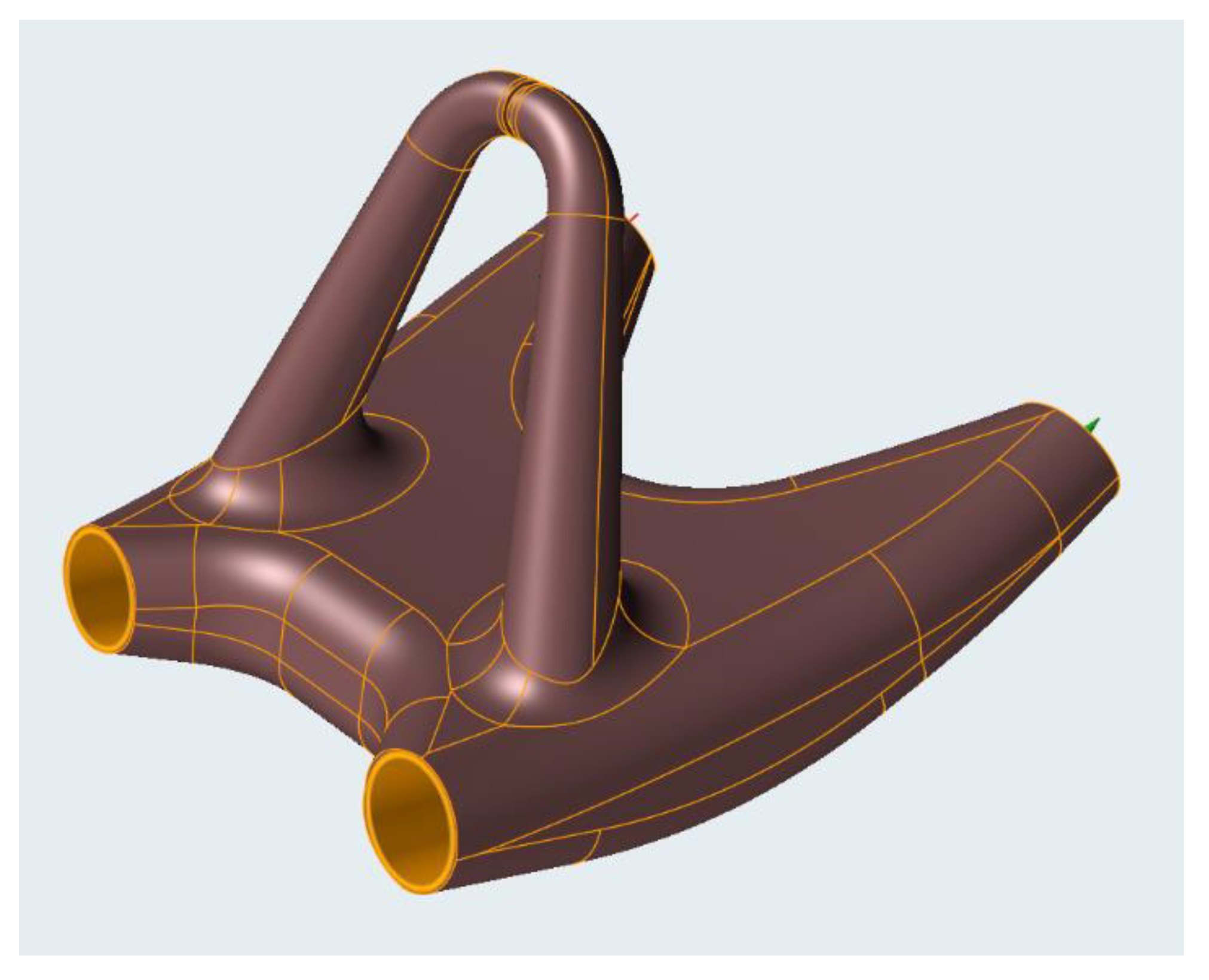
A second variant, an organic and partially shell-shaped model, was considered [8]. Finally, a bionic shape was chosen for production due to the optically slimmer design underlining the lightness of the scooter frame. Bionic shape means an organic, biologically inspired design, which resembles systems found in nature (see Figure 4).
2.2. Design Area
The first boundary condition of the topological optimization is to determine the design area. It is a geometrically determined space in which optimization can take place, with respect to the maximum volume in which the future analysis solution must be located. The limiting factors in the design area creation are, in particular, the maximum possible installation dimensions, in which the part will still be able to be mounted with no collisions with the surroundings. In essence, the resulting design area itself should be a mountable and usable part that will perform its function and will not interfere with the rest of the mechanism [9].
The goal is to make this area as voluminous as possible for analysis, allowing software to be as spacious as possible. First, the design area of the entire scooter frame, shown in Figure 5, was developed. This respects the necessary geometric parameters such as fork tilt, footbar height, chassis ground clearance, and wheelbase.
This design area was then divided into parts corresponding to individual frame parts. In the case of the rear heel, the limiting geometrical condition was the overall width. As such, a 100 mm maximum was determined. When exceeded, it would be no longer comfortable to kick with the foot while riding. In addition, the rear wheel cut-out mounting holes for later bonding of the connecting profiles and the protective bar to protect the foot from entering the wheel when the foot slips were designed.
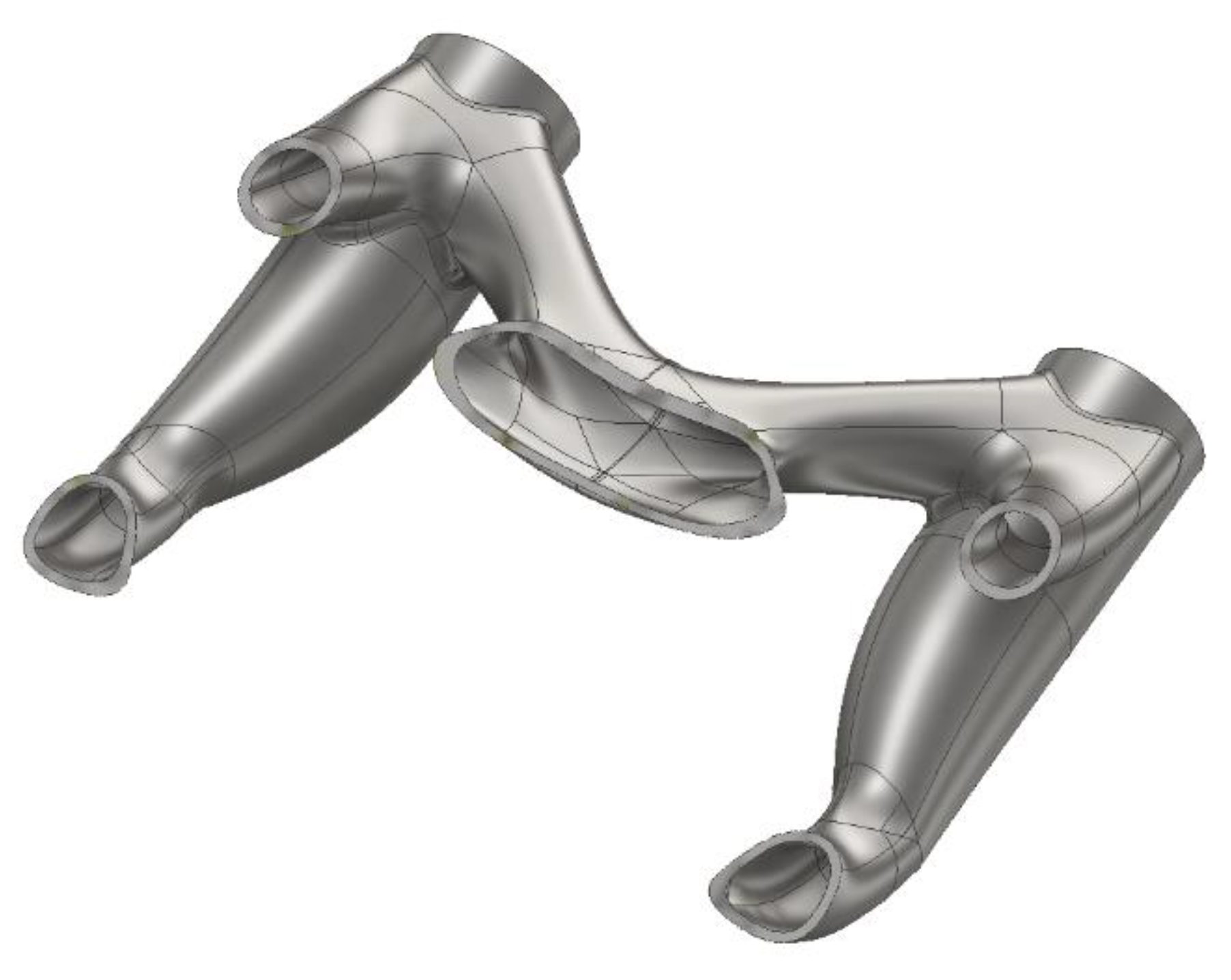
After defining these requirements, the design area of the heel was finally adjusted to the shape seen in Figure 6.
2.3. Load Cases
For topological analysis, it is necessary to define the load cases, for which the calculation and then the FEM analysis will be calculated [10]. These load cases were created for the entire scooter frame and then referenced to the heel part itself. Four critical states were defined in total.
2.3.1. Vertical Impact
This load case is considered as a vertical impact caused by free fall of the scooter with a rider from a height of 1 m. It simulates a jump with a scooter, and subsequently, a steep crossing of an obstacle like a kerb or hump. A 75 kg rider imposes a static load of 736 N on the frame, a value which has been multiplied by a dynamic load factor of 3 g, resulting in a loadcase value of 2210 N.
2.3.2. Braking
The load case was simulated as braking with a slowdown of 5 m·s−2, when the mass is transferred to the front wheel and mainly the front frame part and the fork neck is stressed.
2.3.3. Driving on a Flat with Allowed Deflection
This case should take into account the maximum possible deflection of the frame under the load of the rider in order to avoid excessive frame distortion while riding and collision of the chassis with the road during kicking. The case was determined experimentally by measuring the properties of a conventional scooter, where the maximum deflection of the lower chassis under the load of a rider weighing 80 kg was set at 11 mm while maintaining a minimum chassis clearance of 60 mm.
2.3.4. Torsion
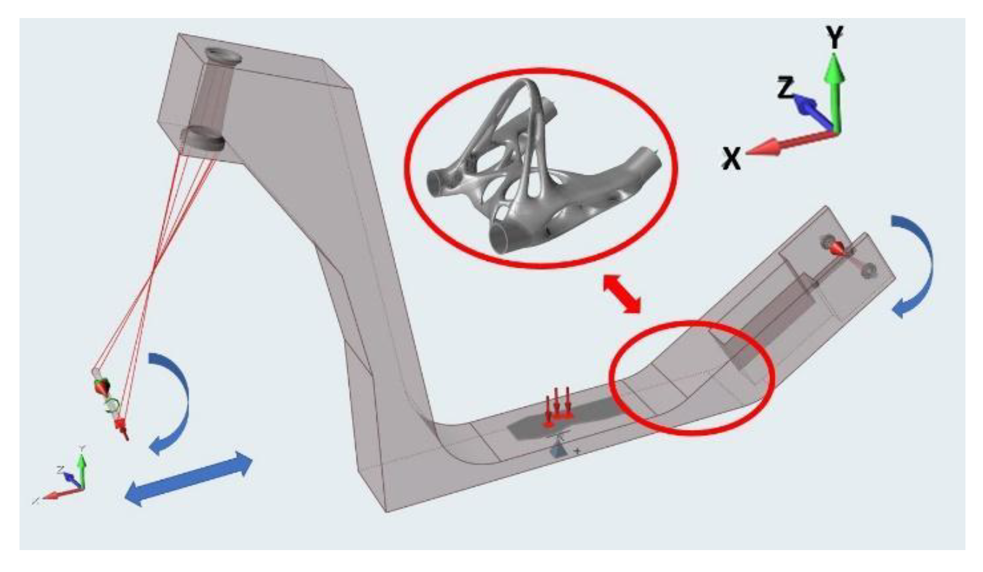
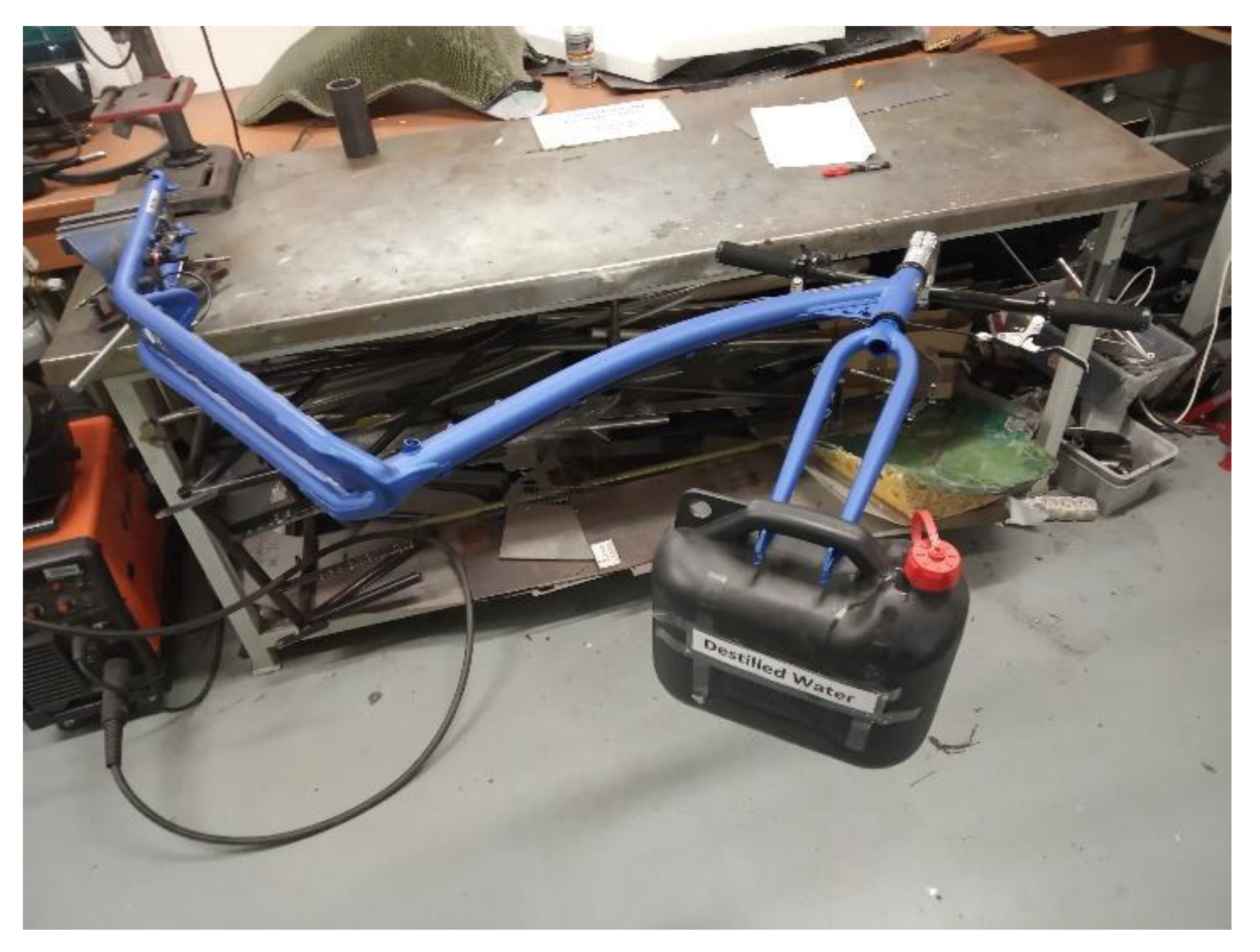
This case takes into account the torsional stiffness of the scooter so that the frame is not twisted and deformed when cornering. It was also determined experimentally on a conventional frame. The frame was firmly fixed and the front fork was gradually loaded to the maximum 100 N force perpendicular to the transverse symmetry plane of the frame. The frame deflection was then measured at the neck. At 100 N, a maximum allowable neck deflection of 30 mm was determined. The experiment is shown in Figure 7.
2.3.5. Final Load Case
The resulting representative load case was determined after several analyses to reflect the critical stress for the heel part. It consists of a combination of vertical impact and torsion, with maximum deflection checked after analyses. Basically, braking was eliminated because it mainly strains the front of the frame and relieves the rear.
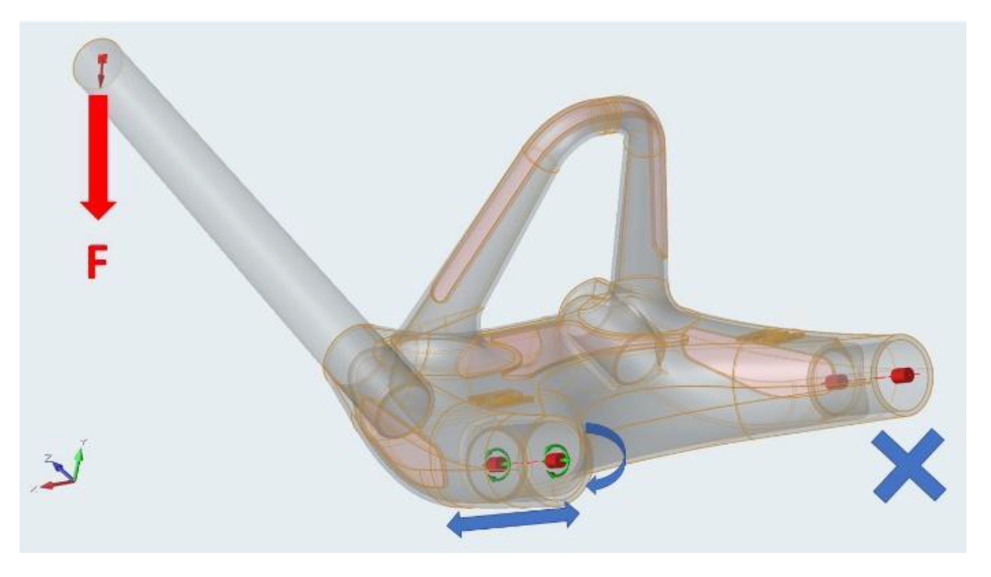
The support pattern in the computing model is shown in Figure 8. The heel is clamped from one rear sleeve, which is fixed. The second rear sleeve has the ability to move and rotate in its axis (sliding), but not perpendicular to the axis (it represents the support in the rear wheel). One front sleeve is left loose and the other is loaded with a force on the length equal to the distance of the step centre. This force simulates the load of vertical impact, explained in Section 2.3.1, with the rider standing unevenly on the scooter axis, representing the torsion. The static force in one arm is increased with a dynamic load factor of 3 g to 2210 N.
2.3.6. Material
For the correct analysis setting, it is also necessary to know the material from which the optimized component will be manufactured. The heel is made of 316 L stainless steel. The part will be printed from atomised powder supplied by the machine manufacturer, RENISHAW. An advantage of the powder-printed part is the improved mechanical properties in comparison with the same material in the form of metallurgical preform products, especially Yield Strength and Tensile Strength [11]. Table 1 lists the important mechanical properties of 316 L-printed material [12].
2.4. Topological Calculation
The topological calculation itself was performed using the SolidThinking Inspire (Altair, Troy, MI, USA) software [13]. The software uses OptiStruct solver core for optimization. OptiStruct uses the density method, called also the SIMP method (Solid Isotropic Material with Penalisation) to solve topological optimization tasks [14].
The process of topological optimization is related to the distribution of material and the way of joining members within the structure. For each element, the so-called “equivalent density” is defined and treated as a design variable. The value of this variable is then calculated for each element. A value of 1 is equivalent to 100% of the material and a value of 0 is equivalent to no material. The solver first attempts to assign low stress and equivalent density value elements before analyzing the impact on the remaining structure. In this manner, the density of the extraneous elements is close to 0, with the ideal design approaching a value of 1. The assumption is that the stiffness of the material is linearly dependent on its density. It is a designer’s judgment which dictates where the limit is, which elements should be left, and which ones omitted. To display the “remaining” structure, an iso-plot of element densities is used, hiding elements with a density below a certain value, so that an optimal design can be seen.
Therefore, to enforce the final design to be expressed by densities of 1 or 0 for each element, we need to use the techniques to penalize intermediate densities. The “power law representation of elasticity properties” penalization technique is exploited in OptiStruct. For any 3D or 2D element it can be expressed as shown in Equation (1):
K(r) = ρp K
K and K represent the penalised and the real stiffness matrix of an element. ρ is the density and p the factor of the penalisation which is always greater than 1.
The DISCRETE parameter correlates with (p − 1) in OptiStruct, DISCRETE can be defined on the DOPTPRM bulk data entry. A value between 2.0 and 4.0 is usual for factor p. For example, if we compare the non-penalised formulation (which is equivalent to p = 1) at ρ = 0.3, with p = 2 the stiffness of the element is reduced from 0.3 to 0.09 times the stiffness of the fully dense element. For shell-dominant structures, the default DISCRETE is 1.0 and for solid-dominant structures is 2.0. The dominance is defined by the number of elements ratio. DISCRT1D is an additional parameter which can also be defined on the DOPTPRM bulk data entry. DISCRT1D enables 1D elements to use a different penalisation to 2D or 3D elements [15].
The penalty starts at 2 for the first iteration, when the minimum member size control is used. For the second and third iterations, it increases to 3. This approach provides a more discrete solution. It is clear that when entering the next iteration phase with a different penalisation factor, the analysis results may vary significantly due to the existence of semi-dense element.
The method of topological calculation was set to maximize the rigidity of the structure but to utilize just a defined portion of the inceptive volume/mass and “shape” to make the shape as stiff as possible [16]. The progressive analysis settings were performed with a final element size of 1 mm and a contact setting as a sliding only. This setting shown in Table 2 has proven to be the most suitable over several iterations [17].
Before the calculation, the planar symmetry was set. This symmetry constraint is used to generate symmetric shapes by specifying symmetry planes in the design space. In this case, the longitudinal plane of the scooter was used. This constraint can be used even under asymmetric conditions.
It is also necessary to define “partitions” in the analysis. These are places that are not subject to analysis and should remain in their original shape. Typically, these are different mounting holes and functional surfaces. In the case of the heel, the partitions were defined at the point of attachment of the composite tubes, shown in Figure 6 in yellow.
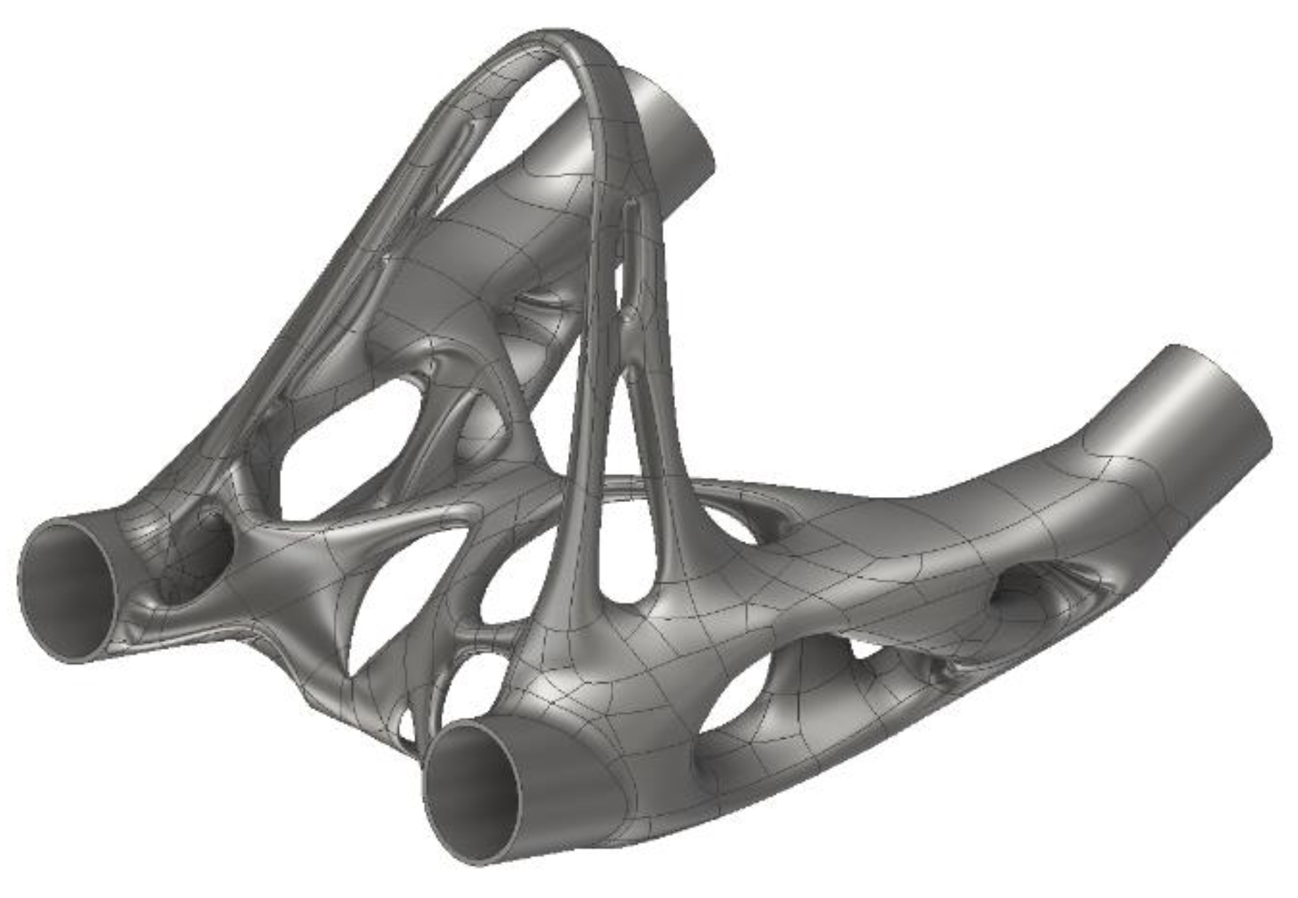
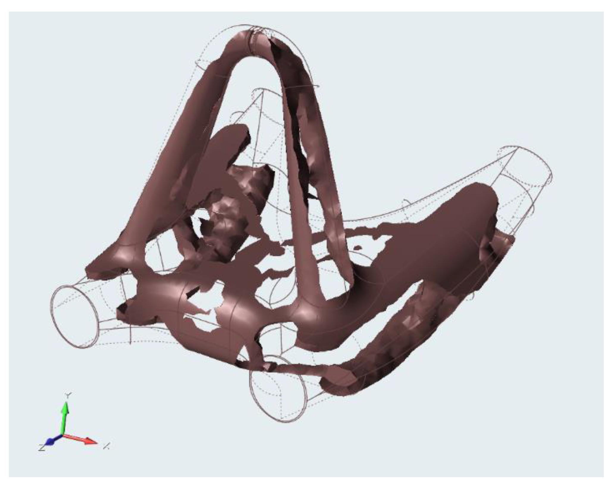
The result of the analysis is the structure of the elements, shown in Figure 9. The calculation leaves the elements only where the load is transmitted [18]. After the analysis, the percentage of the material represented as the density of the elements can be additionally tuned. This element network serves as a support for subsequent modelling afterwards [19]. The output from the optimization process provide the draft design of the part. The concept shape needs to be smoothed and remodeled. The correct interpretation (smoothing) of the draft design actually has a huge impact on the end result, especially on the weight.
2.5. Solid Model Creation
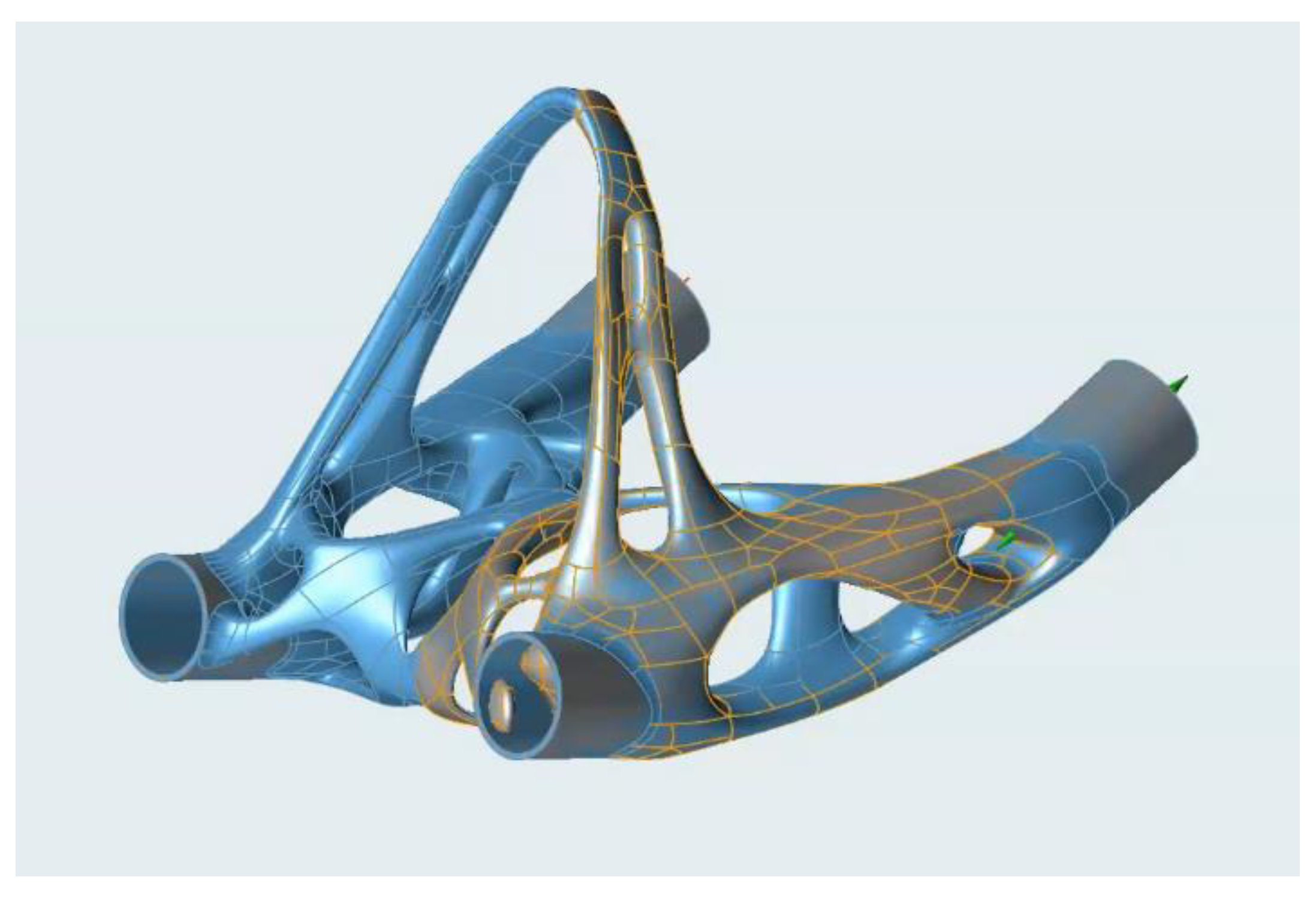
The CAD model itself is created using non-parametric volume modelling based on the analysis results. In the case of the heel, the initial organic model was created in SolidThinking Inspire software, which allows PolyNURBS based modelling. It is a freeform modelling method where a non-parametric model is formed by connecting organic blocks and surfaces to each other. It is a manual way of modelling performed by the designer, where these geometric elements are being extracted from the topological optimization result. The organic shape should trace over the optimization result precisely. The elements are further shaped, interconnected, and formed into a final appearance, as shown in Figure 10.
One iteration of the rear heel considered was the shell part, where further lightening would occur. Moreover, the solid model created above would be partially hollowed in thick areas. It was a repetitive process of finding the ideal wall thickness, which was always verified by an FEM analysis. Ultimately, the sufficient thickness of the wall was found to be 1.3 mm. Shell modelling was performed using Autodesk Inventor software by surface modelling.
However, this shell heel part shown in Figure 11 was not used on the frame. It would be technologically difficult to remove unbaked powder from the cavities (requiring drilling holes). The weight reduction was minimal, but the maximum von Mises stress increased.
2.6. FEM Analysis
The FEM analysis served both to validate the individual steps during the design and to final check the stiffness and strength of the frame part. The analysis was also performed in SolidThinking Inspire software.
Inspire creates and uses mesh during optimization as well during analysis. Meshing setup and creation happens in an automated meshing step in the background using a powerful algorithm to calculate mesh size. Inspire uses a combination of HyperMesh and Simlab for meshing—both could be considered the best meshing tools. If needed, a user can take control of mesh sizes for different components, but usually, the default mesh size gives the best results. The final analysis was performed as a structural analysis with a mesh element size of 1 mm. Supports and load forces were used the same as in the optimization calculation.
In particular, two values were investigated during the analysis: the maximum stress and the flow of stress in the structure, then the maximum displacement/rotation of the heel under the load [20].
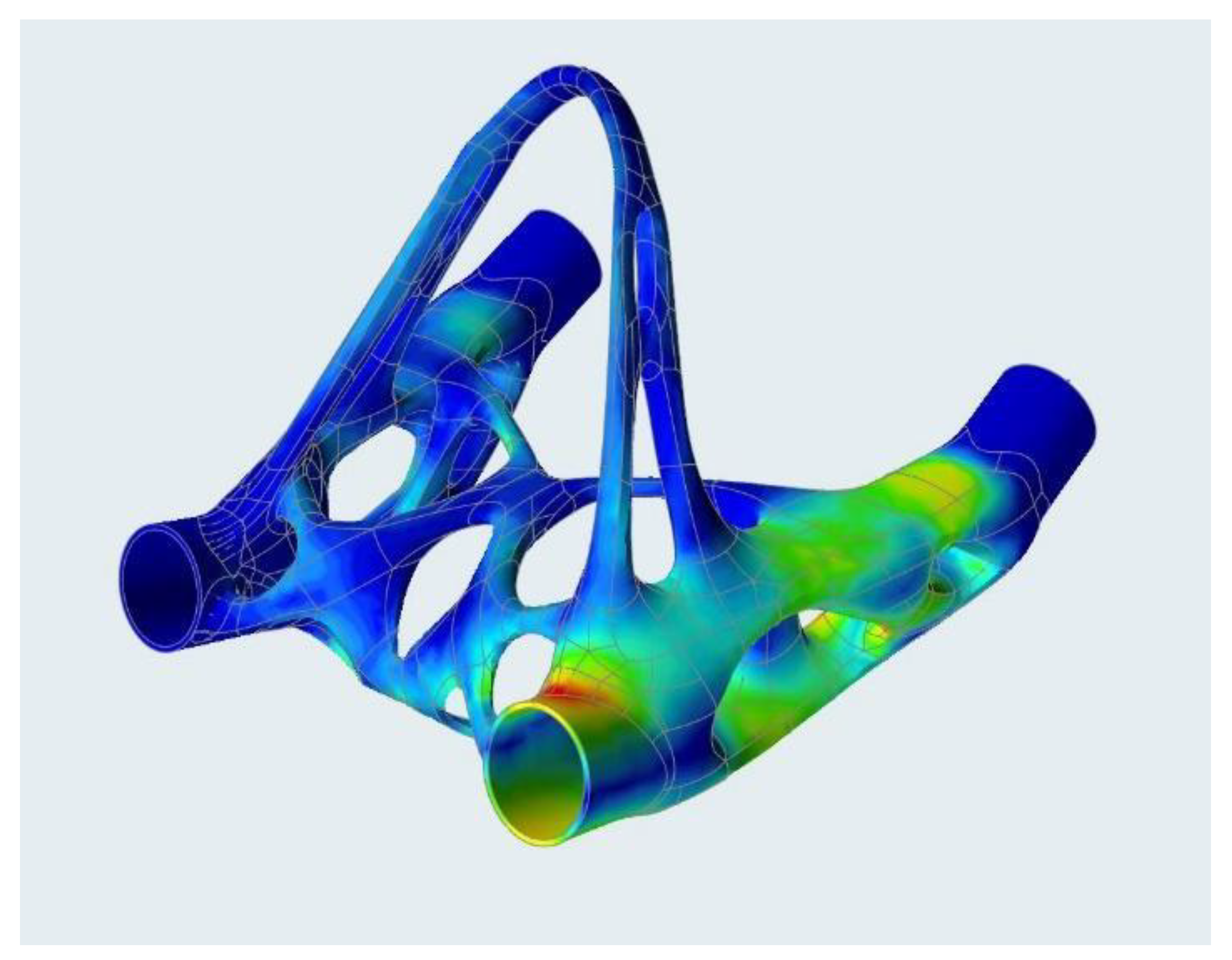
Thanks to the bionic design, which already contains the minimum of stress concentrators from the design principle, the stress is evenly distributed throughout the part and the stress peaks, common in machined parts, are eliminated by optimization itself. The stress flow and stress peak at the connection point of the sleeve is shown in Figure 12.
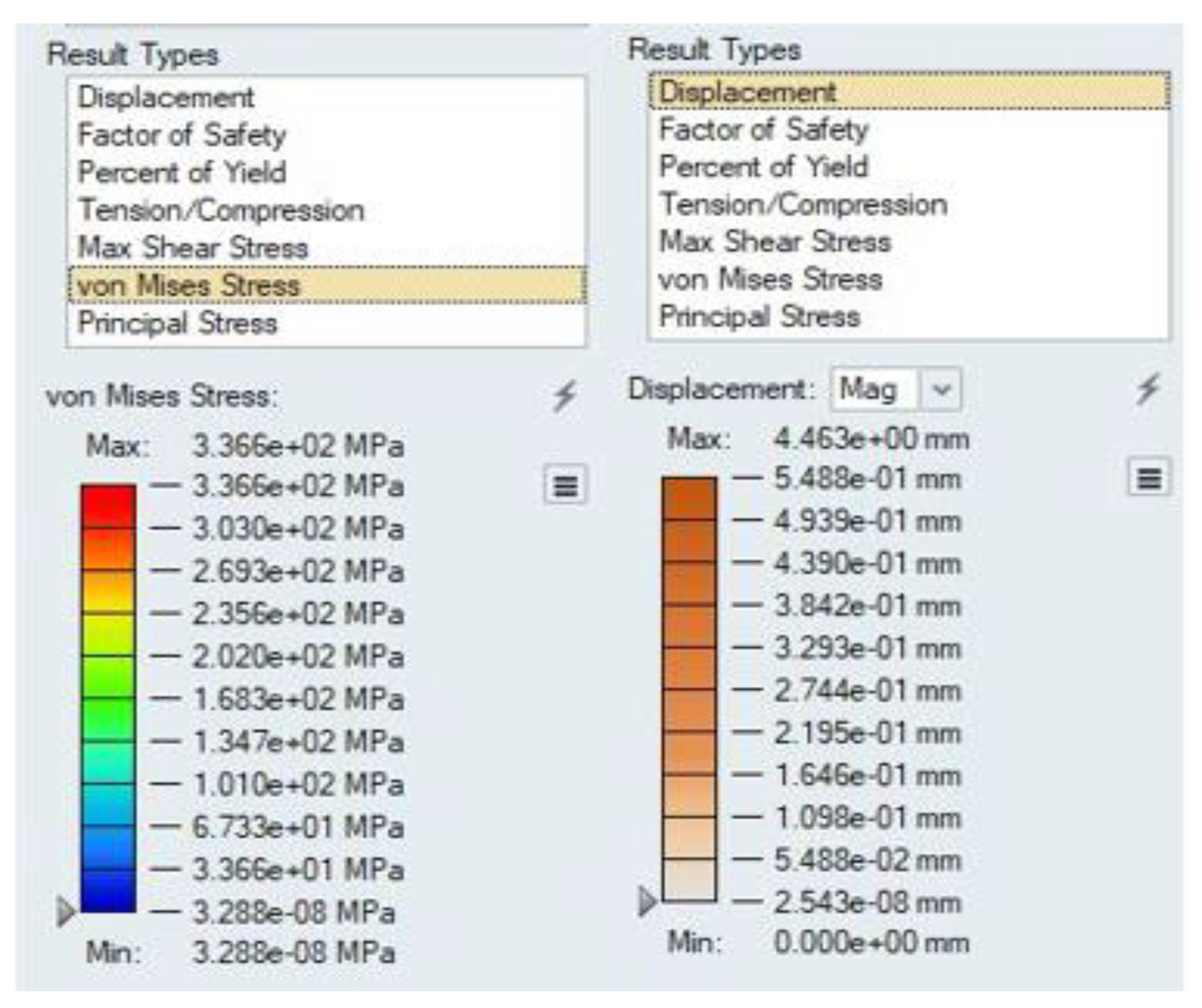
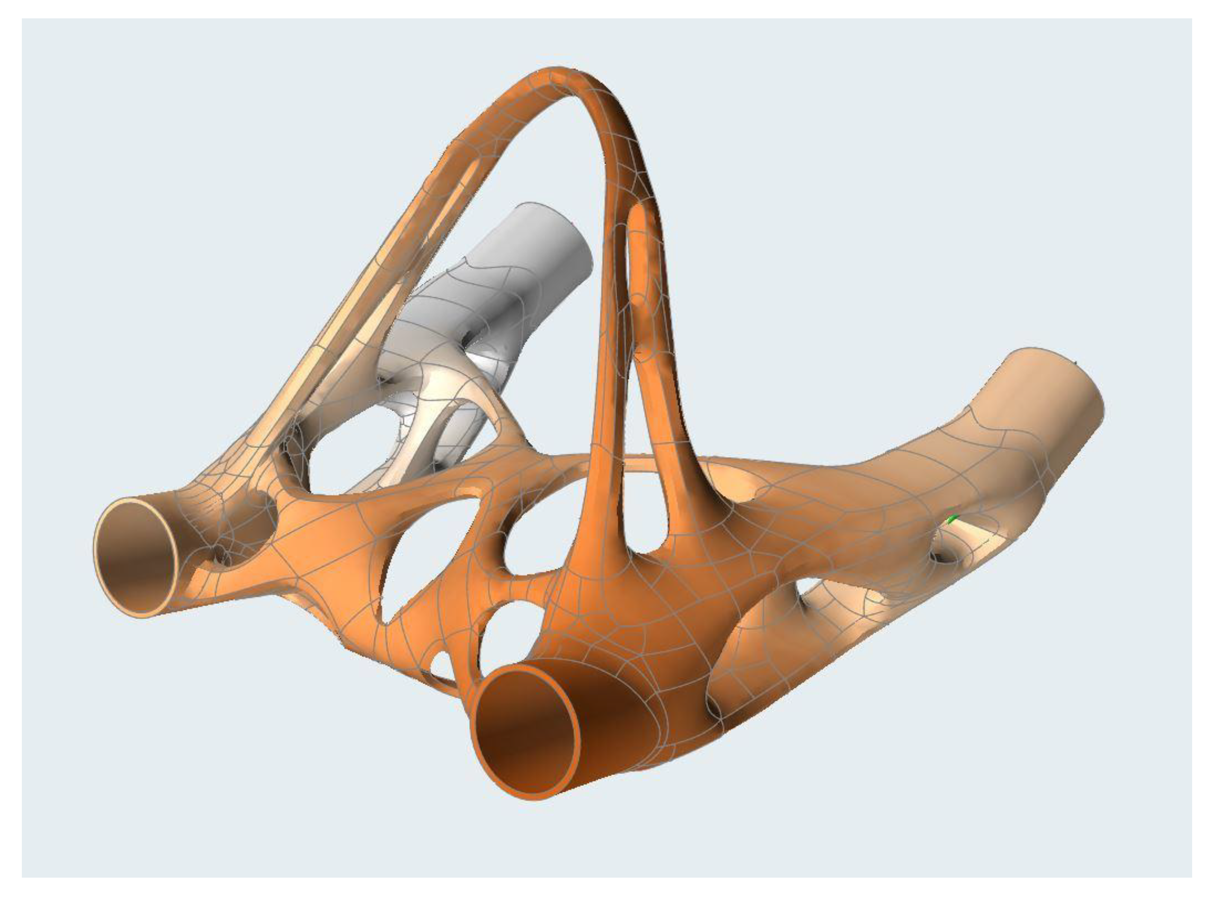
The maximum stress value in the material is 336 MPa, with the maximum displacement at the point of connection of the chassis tube being 5.5 mm (see Figure 13). After checking the geometry in the CAD software, this displacement value was shown to satisfy the maximum allowable tread deflection condition. The heel twisting under the load and displacement distribution is shown in Figure 14.
Compared to the initial design area, the volume of material was reduced to 22%, from the original 385 cm3 to 83 cm3. The weight of the part decreased from 3075 g for the design area to 600 g for the optimized part. This calculated weight differs slightly from the real weight due to the subsequent machining and grinding.
There was no FEM analysis performed for the design area since the area is only a volume boundary condition. Moreover, the foot was created as a completely new part, so it is not possible to compare it with the original variant. However, we can say that thanks to the use of additive production, material savings were made since 3D printing is an almost waste-free technology. Moreover, there is no need for complex machining with several clamping operations, which reduces production time and cost.
2.7. Manufacturing
The heel, as well as the rest of the scooter frame, was made using an SLM (selective laser melting) 3D printer. The printing was carried out on the RENISHAW AM400 machine. Print data preparation was done with a combination of QuantAM and Autodesk NetFabb software. The frame is printed from 316 L stainless steel and a 50 µm layer thickness was used [21].
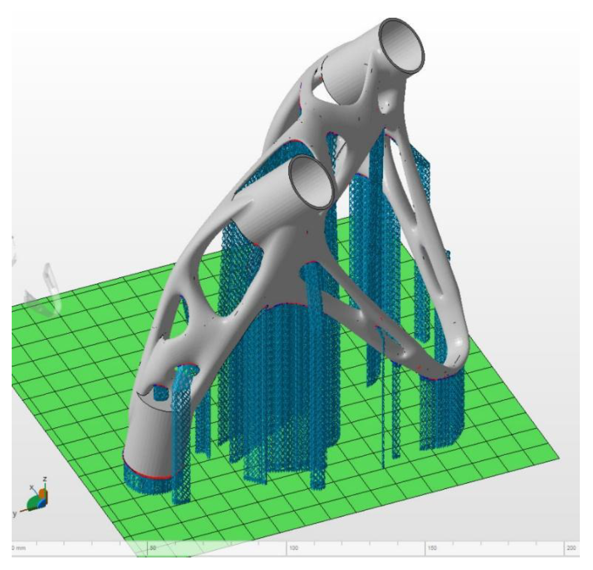
All parts of the frame were divided into two builds. The orientation of the heel in the building chamber was chosen with respect to minimising supports and placing them in well removable locations as is shown in Figure 15. The critical support angle was set to 40° [22].
The heel print time after setting the part orientation in the chamber was 16 h, with the resulting weight after removing the supports being 580 g.
3. Conclusions
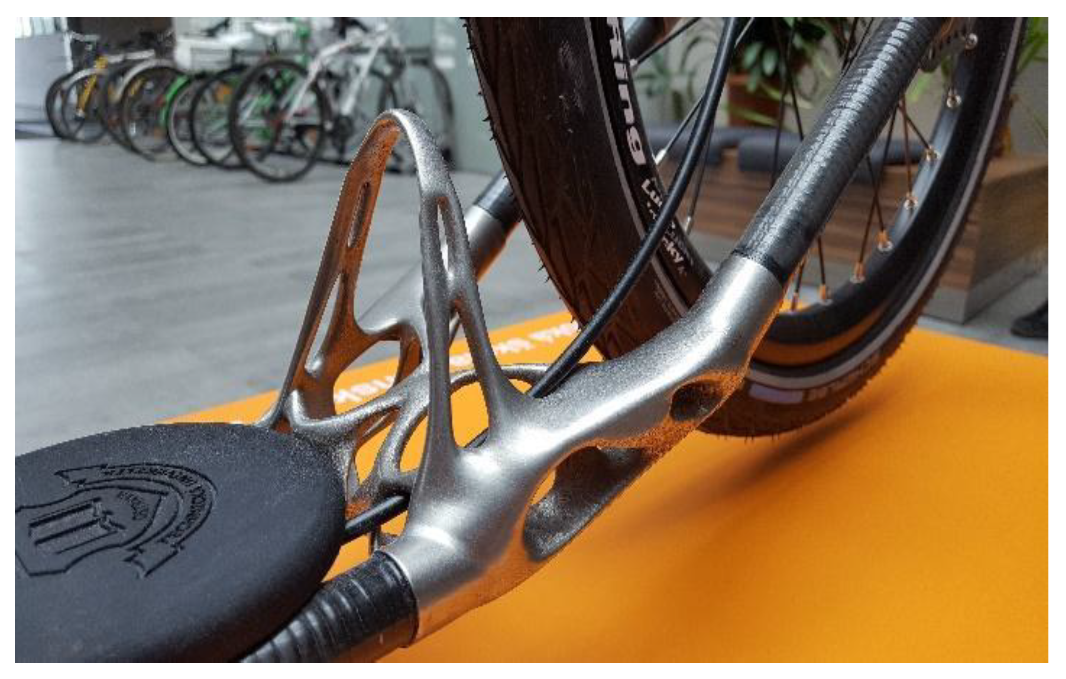
This article describes a method of designing a topologically optimized part using the example of a scooter frame part. It shows the whole design process from the creation of geometric boundaries, through the possibilities and method of setting the analysis, creation of CAD data and FEM validation. This approach was successfully implemented and the resulting part was actually created. The whole scooter was manufactured and is successfully operational, and the produced and finished heel part can be seen in Figure 16.
The strongest property of such a designed part is the attractive and unique design and weight reduction compared to conventional scooter frame parts. Due to CAD data, there is the possibility of quick design changes and parameterisation implementation. This also brings the possibility of customisation and adaptation of the frame geometry to the rider’s needs. Moreover, material changes can be made quickly.
This approach is appropriate mainly for fast small-lot production, without the need for fixtures and single-purpose equipment or automation. On the other hand, as the number of pieces increases, its efficiency decreases. In this case, the approach using free-form modelling becomes inappropriate, because organic shapes are very complicated for conventional methods (for example, casting) and have to be redesigned.
Author Contributions
Conceptualization: L.J., M.P., J.M. and P.S.; methodology: L.J. and J.M.; software: L.J. and J.M.; validation: L.J.; formal analysis, L.J.; investigation: L.J.; resources: L.J.; data curation: L.J.; writing—original draft preparation: L.J.; writing—review and editing: L.J., M.P. and J.M.; visualization: L.J.; supervision: M.P. and P.S.; project administration: M.P. and P.S.; funding acquisition: M.P. and P.S. All authors have read and agreed to the published version of the manuscript.
Funding
The research was funded in association with project Innovative and additive manufacturing technology—new technological solutions for 3D printing of metals and composite materials, reg. no. CZ.02.1.01/0.0/0.0/17_049/0008407 financed by Structural Funds of the European Union and project.
Acknowledgments
This article has been completed in association with project Innovative and additive manufacturing technology – new technological solutions for 3D printing of metals and composite materials, reg. no. CZ.02.1.01/0.0/0.0/17_049/0008407 financed by Structural Funds of the European Union and project. This article has been elaborated in the research project Research Centre of Advanced Mechatronic Systems, reg. no. CZ.02.1.01/0.0/0.0/ 16_019/0000867 in the frame of the Operational Programme Research, Development and Education.
Conflicts of Interest
The authors declare no conflict of interest.
References
- Sadri, M.; Kavandi, M.; Jozepiri, A.; Teimouri, S.; Abbasi, F. Bionic Architecture, Forms and Constructions. Res. J. Recent Sci. 2014, 3, 93–98, ISSN: 2277-2502. [Google Scholar]
- Nickels, L. 3D printing the world’s first metal bicycle frame. Met. Powder Rep. 2014, 69, 38–40, ISSN: 0026-0657. [Google Scholar] [CrossRef]
- Destro, M. Simulations of Oblique Impacts on Regular and Hierarchical Lattice Structures. 2019. Available online: http://tesi.cab.unipd.it/62511/1/Destro_Matteo_1147958.pdf (accessed on 18 February 2020).
- Podroužek, J.; Marcon, M.; Ninčević, K.; Wan-Wendner, R. Bio-Inspired 3D Infill Patterns for Additive Manufacturing and Structural Applications. Materials 2019, 12, 499. [Google Scholar] [CrossRef] [PubMed] [Green Version]
- Yang, Y.; Xin, X.; Bin, Z.; Wei, Z.; Yidi, W. Bionic design for the aerodynamic shape of a stratospheric airship. Aerosp. Sci. Technol. 2020, 98, 105664, ISSN: 1270-9638. [Google Scholar] [CrossRef]
- Ding, Y.; Zhou, Z.; Wang, Z.; Liu, H.; Wang, K. Bionic Stiffener Layout Optimization with a Flexible Plate in Solar-Powered UAV Surface Structure Design. Appl. Sci. 2019, 9, 5196. [Google Scholar] [CrossRef] [Green Version]
- Liu, J.; Ou, H.; He, J.; Wen, G. Topological Design of a Lightweight Sandwich Aircraft Spoiler. Materials 2019, 12, 3225. [Google Scholar] [CrossRef] [Green Version]
- Yan, S.N.; Li, B.; Hong, J. Bionic design and verification of high-precision machine tool structures. Int. J. Adv. Manuf. Technol. 2015, 81, 73–85, ISSN: 0268-3768. [Google Scholar] [CrossRef]
- Bendsoe, M.P.; Sigmund, O. Topology Optimization: Theory, Methods and Applications; Springer: Berlin, Germany, 2003; ISBN 3-540-42992-1. [Google Scholar]
- Jiang, D.; Hoglund, R.; Smith, D.E. Continuous Fiber Angle Topology Optimization for Polymer Composite Deposition Additive Manufacturing Applications. Fibers 2019, 7, 14. [Google Scholar] [CrossRef] [Green Version]
- Hajnyš, J.; Pagáč, M.; Zlámal, T.; Petrů, J.; Kousal, L. Stiffness of 316L stainless steel support structures proposed for the SLM process. MATEC Web Conf. 2018, 244. [Google Scholar] [CrossRef]
- Renishaw Plc. Data Sheets—Additive Manufacturing. Renishaw, 2019, UK. 9.7.2019 [11.7.2019]. Available online: https://www.renishaw.com/en/data-sheets-additive-manufacturing--17862 (accessed on 16 August 2019).
- solidthinking, Inc. Altair Inspire: Generate Structurally Efficient Concepts Quickly and Easily. 5.10.2019 [12.3.2020]. Available online: https://solidthinking.com/product/inspire/ (accessed on 16 March 2020).
- Bendsoe, M.P. Optimal shape design as a material distribution problem. Struct. Optim. 1989, 1, 193–202. [Google Scholar] [CrossRef]
- Advanced Engineering, Practical Aspects of Structural Optimisation. 3.8.2018 [12.3.2020]. Available online: https://advanced-eng.cz/ke-stazeni/optimization-ebook/ (accessed on 16 March 2020).
- Ismail, A.Y.; Na, G.; Koo, B. Topology and Response Surface Optimization of a Bicycle Crank Arm with Multiple Load Cases. Appl. Sci. 2020, 10, 2201. [Google Scholar] [CrossRef] [Green Version]
- Jiang, L.; Ye, H.; Zhou, C.; Chen, S. Parametric Topology Optimization Toward Rational Design and Efficient Prefabrication for Additive Manufacturing. J. Manuf. Sci. Eng. Trans. ASME 2019, 141, 041007, ISSN: 1087-1357. [Google Scholar] [CrossRef]
- Zhu, D.; Zhan, W.; Wu, F.; Simeone, A. Topology Optimization of Spatially Compliant Mechanisms with an Isomorphic Matrix of a 3-UPC Type Parallel Prototype Manipulator. Micromachines 2018, 9, 184. [Google Scholar] [CrossRef] [PubMed] [Green Version]
- SolidThinking, Inc. solidThinking Inspire 2017.2. 16.3.2017 [11.7.2019]. Available online: https://solidthinking.com/help/Inspire/2017.2/win/en_us/index.html?welcome.htm (accessed on 2 August 2019).
- Pagac, M.; Hajnys, J.; Petru, J.; Zlamal, T.; Sofer, M. The Study of Mechanical Properties Stainless Steel 316L After Production from Metal Powder with Using Additive Technology and by Method Selective Laser Melting. METAL 2017. In Proceedings of the 26th Anniversary International Conference on Metallurgy and Materials, Brno, Czech republic, 24–26 May 2017; pp. 962–967, ISBN 978-80-87294-79-6. [Google Scholar]
- Liu, Y.; Li, Z.; Wei, P.; Chen, S. Generating support structures for additive manufacturing with continuum topology optimization methods. Rapid Prototyp. J. 2019, 25, 232–246, ISSN: 1355-2546. [Google Scholar] [CrossRef]
- Garaigordobil, A.; Ansola, R.; Veguería, E.; Fernandez, I. Overhang constraint for topology optimization of self-supported compliant mechanisms considering additive manufacturing. Comput. Aided Des. 2019, 110, 33–48, ISSN: 0010-4485. [Google Scholar] [CrossRef]
Figure 1.
Block diagram of the optimization workflow.

Figure 2.
Three-dimensional printed scooter with bionic frame.

Figure 3.
First heel version with lattice structure inside.

Figure 4.
Second heel version with bionic design.

Figure 5.
Frame design area with heel location shown.

Figure 6.
Modified heel design area.

Figure 7.
Torsion measurement experiment.

Figure 8.
Heel load case with force and supports.

Figure 9.
Topology analysis result.

Figure 10.
PolyNURBS CAD model.

Figure 11.
Shell variant.

Figure 12.
Von Mises stress.

Figure 13.
Von Mises stress and displacement results.

Figure 14.
Displacement.

Figure 15.
Orientation in building chamber, supports.

Figure 16.
Printed and mounted heel.


Table 1.
Mechanical properties of 316 L additively manufactured components.
| Steel 316 L—3D Printed Upper Tensile Strength (UTS) | As Built |
|---|---|
| Horizontal direction (XY) | 676 MPa ± 2 MPa |
| Vertical direction (Z) | 624 MPa ± 17 MPa |
| Yield strength | |
| Horizontal direction (XY) | 547 MPa ± 3 MPa |
| Vertical direction (Z) | 494 MPa ± 14 MPa |
| Elongation at break | |
| Horizontal direction (XY) | 43% ± 2% |
| Vertical direction (Z) | 35% ± 8% |
| Modulus of elasticity | |
| Horizontal direction (XY) | 197 GPa ± 4 GPa |
| Vertical direction (Z) | 190 GPa ± 10 GPa |
| Hardness (Vickers) | |
| Horizontal direction (XY) | 198 HV0.5 ± 8 HV0.5 |
| Vertical direction (Z) | 208 HV0.5 ± 6 HV0.5 |
| Horizontal direction (XY) | 4 μm to 6 µm |
| Vertical direction (Z) | 4 μm to 6 µm |
Table 2.
Topology analysis settings.
| Parameter | Set Value |
|---|---|
| Analysis type | Topology optimization |
| Objective | Maximise stiffness |
| Initial mass target | 30% |
| Element size | 1 mm |
| Geometry constraint | Plane symmetry (longitudinal plane) |
© 2020 by the authors. Licensee MDPI, Basel, Switzerland. This article is an open access article distributed under the terms and conditions of the Creative Commons Attribution (CC BY) license (http://creativecommons.org/licenses/by/4.0/).
Share and Cite
MDPI and ACS Style
Jancar, L.; Pagac, M.; Mesicek, J.; Stefek, P. Design Procedure of a Topologically Optimized Scooter Frame Part. Symmetry 2020, 12, 755. https://0-doi-org.brum.beds.ac.uk/10.3390/sym12050755
AMA Style
Jancar L, Pagac M, Mesicek J, Stefek P. Design Procedure of a Topologically Optimized Scooter Frame Part. Symmetry. 2020; 12(5):755. https://0-doi-org.brum.beds.ac.uk/10.3390/sym12050755
Chicago/Turabian StyleJancar, Lukas, Marek Pagac, Jakub Mesicek, and Petr Stefek. 2020. "Design Procedure of a Topologically Optimized Scooter Frame Part" Symmetry 12, no. 5: 755. https://0-doi-org.brum.beds.ac.uk/10.3390/sym12050755
Note that from the first issue of 2016, this journal uses article numbers instead of page numbers. See further details here.