1. Introduction
Geothermal energy is a renewable and clean resource that can be utilized by humans around the world who are located in geologically profitable places. As a renewable resource, geothermal energy exploits the earth’s interior heat, which contains water abundantly, and is sustainable. Currently, for high-temperature geothermal potential, the electricity generated by geothermal power plants incurs a significantly lower cost than fossil fuels, coal, nuclear, gas fuel, wind, and solar energy [
1]. However, many places in the world are endowed with low-temperature geothermal resources, in which power plant equipment cannot be operated directly. Consequently, geothermal energy under 150 °C latent heat must utilize binary cycle technology with an appropriate working fluid to accept heat energy in a heat exchanger such as an ORC system [
2]. Bertanni, 2016 [
3] and Franco et al., 2014 [
4] observed that approximately 70% of geothermal energy worldwide has temperature below 150 °C. Guo et al., 2011 [
5] revealed that the criteria of equipment, such as evaporator, condenser, turbine, and pump, could be reduced to the size of the body; furthermore, the binary cycle provided flexible power capacity in few megawatts.
Working fluid is required in the binary cycle system, thus Yari, 2010 [
6] wrote that the binary cycle uses working fluid which has a low boiling point temperature and high pressure in superheated vapour. The selection of an appropriate working fluid has gained the attention of researchers conducting experiments on efficiency. Franco et al., 2009 [
7] tested several working fluids in ORC experiments and found isobutane, R152a, and n-pentane as compatible working fluids. Wu et al., 2015 [
8] operated an ORC prototype in small-scale with applied R123 and confronted the scroll-type expander performance between simulation computers with experimental data. They chose the R123 refrigerant because of its high system efficiency within the applied temperature range in the test. Meanwhile, R123 is a dry fluid which, at the end of expansion in the scroll expander, can stay away from turning into a two-phase area. Lately, working fluids R245fa and R123 have been widely used in research, such as those reported by Li et al., 2013 [
9], Eyerer 2016 [
10], Shu et al., 2016 [
11], and Shao et al., 2017 [
12]. Surindra et al., 2019 [
13] developed a simulator of a binary cycle test bench with R245fa, R123, and mixed-ratio as the working fluid. They operated binary cycle systems with a mass flow rate of 0.1 to 0.2 kg/s and observed the effects on system performance. It was found that the highest ORC efficiency was created when the binary cycle test bench used R123 working fluid and a heat source at 120 °C.
The ORC is considered a reasonable method for utilizing these geothermal sources; therefore, the preliminary design stage, also known as conceptual design, has been widely carried out by researchers such as Fu et al., 2014 [
14], Hu et al., 2015 [
15], Song et al., 2016 [
16], Kim et al., 2017 [
17], Dickes et al., 2018 [
18], and Erdeweghe et al., 2019 [
19]. Furthermore, some researchers shift their thinking to the detailed design of important elements to examine the relationship between working fluids and the performance of system components. Few seem to be interested in predicting ORC performance in an off-design state; this is due to components not being designed for ORC systems and ORC equipment experiencing performance degradation because of ORC’s continuous operation process, which deviates from the initial design point.
In Canterbury University, New Zealand, a lifetime design strategy was developed by Budisulistyo et al., 2017 [
20] for geothermal power plants. They discovered the potential temperature of geothermal sources and streamed a flow rate decrease over a 40-year life span, with starting temperature and mass flow rate at 131 °C and 200 kg/s, respectively. The calculations of standard ORC design for potential geothermal heat source conditions in years 1, 7, 15, to 30 were estimated and found that the ORC design for year 7, due to partially reducing heat source conditions, indicated the greatest on the whole performance of net present value (NPV) at USD 6.89 and return on energy investment at USD 4.15. Moreover, Budisulistyo et al., 2017 [
20] concluded two strategies for adaptation, which can be used to improve performance in heat source degradation, the lifetime design point, and the technical plant. Thermodynamic properties of the operating ORC system for flow rate of working fluid and flow rate of air in the condenser could be adapted or flow diagram changes could be developed, such as installing a recuperator in one half of the system to preheat working fluid or an initial vapouriser at the end of the service cycles.
Manete et al., 2013 [
21] presented a complete off-design model of an ORC for a low enthalpy heat source geothermal power plant, which consists of a performance diagram of each main component system, such as pump speed, turbine capacity, and air flow rate in the condenser. They revealed an influenced varying temperature of heat source between 130 and 180 °C and differences in environment temperature at 0 to 30 °C. Off-design modelling was developed to find the best operating system by assuming that the mass flow rate affects the overall coefficient of heat transfer. The authors concluded that optimal operation strategy in off-design could be conveniently applied to existing plants and to the new design plant configurations. Furthermore, they declared that the environment temperature exceptionally influencing the performance of the ORC system, due to varying geothermal heat source temperature, would be affected by the air-cooled system and thus, affect the electrical power output.
Low enthalpy geothermal resources for power generation using organic Rankine cycle systems are grossly affected by the temperature level of the heat sink and heat source. Usman et al., 2017 [
22] matched the performance in different load operations of an air-cooled system and a cooling tower based on low-temperature heat sources from a geothermal ORC system constructed at varied demographic locations and different climate conditions. They compared two different temperature geothermal heat sources, in which the first had a temperature of 130 °C and a flow rate of 9.16kg/s, and the second had a temperature and flow rate of 145 °C and 6.57kg/s, respectively. In off-design modelling, the heat sink was controlled to catch optimum power output at varied environment conditions, with weather data illustrating ambient conditions of Ulsan, London, Vegas, and Kuala Lumpur. They developed mathematical models for condenser part load operations as a formulation of both air-cooled and mechanical draft wet cooling tower-based ORC systems. The authors recapitulated that environmental conditions significantly influence power output. In summer, the decrease in power output could be 62% from the capacity in winter. Additionally, they revealed that it was more suitable to use a cooling tower for ORC systems in hot dry regions, whilst air-cooled ORCs can be implemented in other climates.
Thermo-economic analysis combines economic analysis and thermodynamics by applying the concept of cost, initially an economic property, to exergy at low-temperature heat sources in a geothermal energy system as some researchers have done, including Heberle et al., 2014–2015 [
23,
24], Proctor et al., 2016 [
25], Wieland et al., 2016 [
26], Liu et al., 2017 [
27], Yao et al., 2018 [
28], and Eller et al., 2019 [
29]. Important components of the ORC system mainly consist of a pump, expanders, and heat exchangers, which have a significant impact on the performance of the thermo-economic system. Keef et al., 2019 [
30] developed a framework for optimally designing organic Rankine cycle (ORC) power systems, which, at the same time, takes into account both thermodynamic and economic goals. The system of method used, in particular the computer-aided molecular design (CAMD) technique, enables the identifying of working fluid maximally over optimization systems for a thermo-economic purpose. The next step is to implement a framework plan on the design of subcritical and non-recuperated ORC systems in different applications that cover various heat source temperatures. When reducing the specific investment cost (SIC) for systems, Keef et al., 2019 [
30] found that the optimal molecular size of the working fluid is related to the temperature of the heat source, as intended, but also that the recognition of a minimum pinch point limitation, which normally used to take into account the innate exchange between system performance and cost, is not required. The authors claimed that the same molecules were accounted for in a multi-objective optimization, reflecting both the total investment cost and net power output. Furthermore, they concluded that the strength of this methodology is the possibility of selecting working fluid while optimizing ORC systems using single or multiple thermo-economic performance indicators.
Heat exchangers (evaporator or condenser) have been a subject of interest for many researchers as the main study object or part of a study. Condenser investigations to improve the effectiveness of heat transfer with liquid-separated condensation, in order to reduce condenser costs, were studied by Li et al., 2019 [
31], which can be assisted with the application of widespread ORC systems. However, several related reports have focused on the shell-and-tube condensers widely used in ORC systems. The authors focused on the superiority of thermo-economic performance and the prevailing working conditions of the liquid-separated condensation method into single-pressure and dual-pressure evaporation ORC systems. Moreover, the authors concluded that in the dual-pressure evaporation ORC system, the liquid-separated condensation method was able to reduce the cost of purchasing a condenser even more tremendously. As a result, the effects of the liquid-separated condensation method on SIC reduction was more significant in the single-pressure evaporation ORC system and more applicable for the pure organic fluid with high critical temperature. Other researchers such as Zare 2015 [
32], Luo et al., 2017 [
33], Wang et al., 2018 [
34], and Shen et al.2019 [
35] also revealed reports related to heat exchangers.
Different points of view regarding heat exchangers have been reported by Arreola et al., 2018 [
36]. They performed a systematic analysis and comparison of the dynamic responses for two types of ORC evaporators during direct heat transfer between flue gas and working fluid. The author built a map to highlight, in the generalized, systematic, and compact strategy, the dependence of the evaporator’s thermal response time on boundary conditions and geometric designs, with their effects on changes in volume, weight, and pressure, based on detailed dynamic models and simulations. Furthermore, the authors concluded that the maps could be a guideline for designing heat exchangers by combining thermal inertia and obtaining optimization.
However, all the studies mentioned earlier, such as preliminary design, thermo-economics, and optimization, revealed that heat exchangers are an important element and are discussed from various perspectives. Generally, researchers make experiments to determine changes in prototype performance or the ORC simulations which they develop. Therefore, information related to equipment varies greatly, and it is essential to know in building an ORC system. Especially, in heat exchangers, the mechanism of heat transfer in evaporators is the starting point on the extent of the ability to explore geothermal potential. Furthermore, limited investigations attempted to take into account the heat transfer coefficients and pinch point of the evaporator. A review of the previous journal papers revealed that the differences in experimental studies using R245fa and R123 as pure working fluid applied in a small-scale binary cycle test bench have been shown. Based on what was found by Surindra et al., 2019 [
13], the present experiment focuses on the effect of a variety of superheated vapours characteristic of evaporator and scroll-type expanders for a binary cycle operation. R123 working fluid is adopted to produce the highest ORC efficiency and environmental performance. The steady-state operation characteristic is firstly considered to keep legitimate and proper experiment data. This paper not only provides a direction to compare binary cycle equipment in an ORC system with theoretical analysis, but also supports the future ORC for industry 4.0.
2. Test Bench Description of ORC System
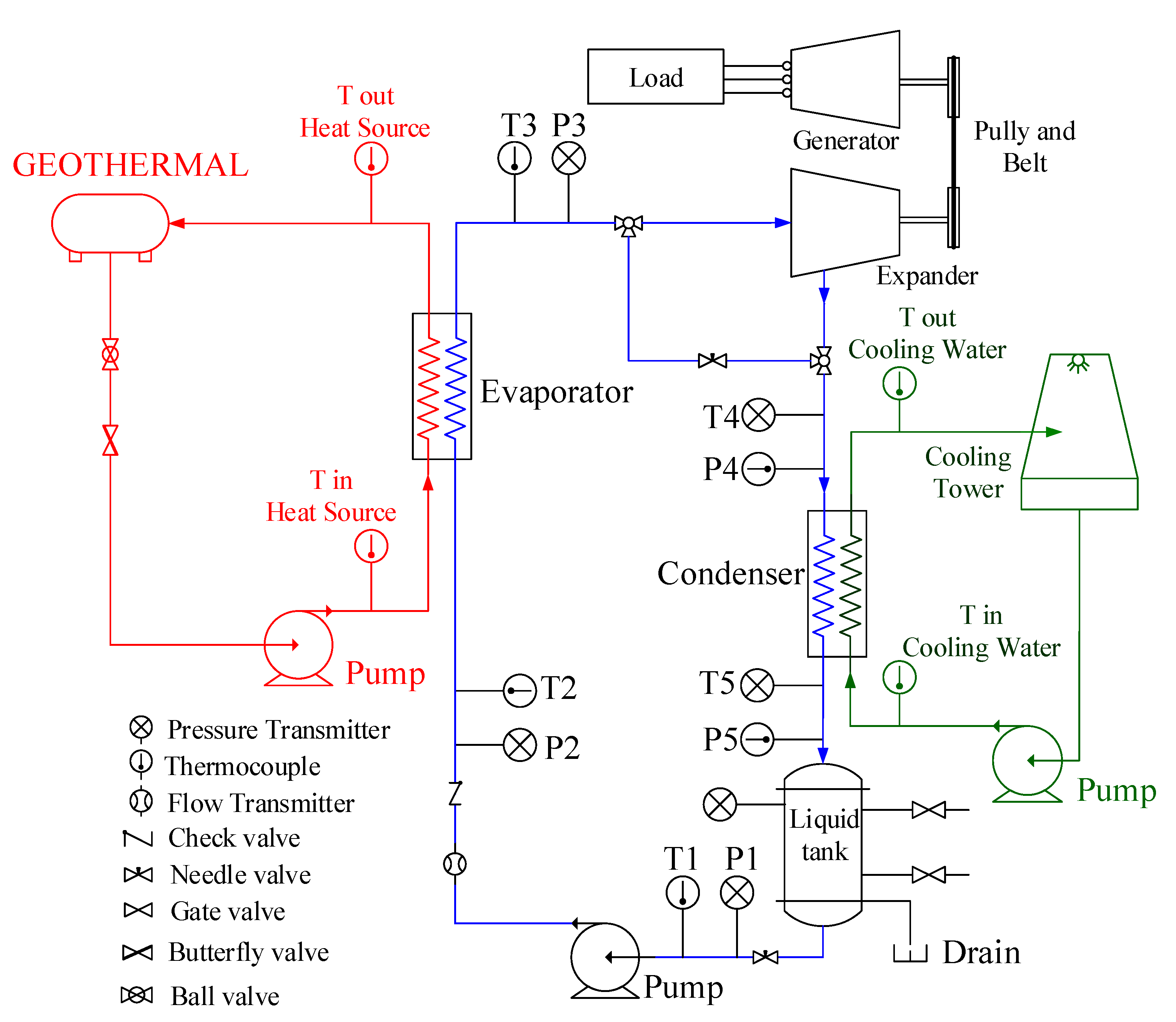
The utilization of heat energy sources from geothermal was simulated by building ORC systems with an applied binary cycle in laboratory scale to investigate the effect of superheated vapour changes on system performance. The scheme in
Figure 1 describes the binary cycle process flow or ORC loop, and the other two supporting circuits, which consist of a heating loop and cooling loop.
2.1. Heating Loop
In the heating loop, as seen in
Figure 1 with the red colour area and visualized by the photo in
Figure 2, the thermal input was provided by about 400 litres of conduction oil and was rated for a thermal power input of 80 kW. The conduction oil utilized lubricating oil, which was produced by the TOTAL Company with type SERIOLA K 3120. Furthermore, lubricating oil has specifications at temperature 120 °C, with a specific heat of 0.535 kcal/kg °C. The hot conductive oil temperature was controlled by switching on/off the electro-resistances of the input power and was regulated precisely at 120 °C to reproduce low grade heat sources. An axial pump adjusted the mass flow rates of the conductive oil, ensuring the heat source temperature was fixed at 120 °C in the evaporator inlet.
2.2. Binary Loop
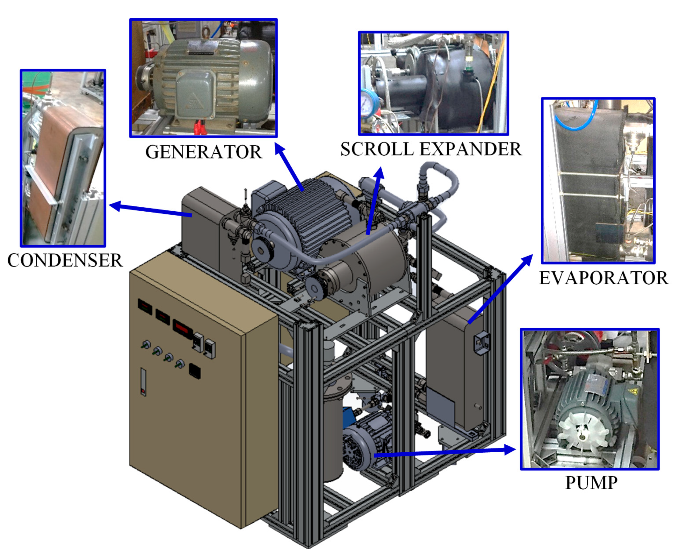
The binary loop was made up of four main components: a piston pump, an evaporator, a scroll-type expander, and a condenser, as seen in
Figure 1 with the blue colour area and visualised by the photo in
Figure 2. In the previous experiment, Surindra et al., 2019 [
13] stated that R123 had the best thermodynamic performance when 120 °C temperature of conductive oil was applied as the heat source. Furthermore, working fluid R123 created the highest ORC efficiency compared to working fluid R245fa and them mixed. Therefore, in this investigation, R123 was used as the working fluid.
The concepts of Ozone Depletion Potential (ODP) and Global Warming Potential (GWP) are a set of national and international considerations discussing ozone protection policies, including amendments to the International Montreal Protocol. Furthermore, the safety of working fluids is a major concern, and therefore, crucial features of working fluids must be non-toxic, non-explosive, non-flammable, and have chemical stability.
Based on this reasoning, the properties of R123 in
Table 1 fulfilled the requirements and are supported by many researchers in the last 5 years using R123 as a working fluid in their research, as stated in
Table 2.
The piston pump supplied working fluid R123 to an evaporator where it was heated and vaporised by conductive oil. Frequency converter devices controlled a piston pump to achieve maximum pressure head and flow rate at 14 bar and 18 litres/minute, respectively. The high-pressure vapour flowed into a scroll-type expander and its enthalpy was converted to work output. The low-pressure vapour originated from a scroll-type expander and led into the condenser, where it was condensed by cooling water. The liquid was available at the condenser outlet, and then, it was pumped back to an evaporator; following this, the process started again.
The plate heat exchanger (PHE) type was applied as the evaporator and condenser, with the area of heat transfer being 4.157 m2 (data sheets information). On the surface of the evaporator, glass wool insulation was installed to prevent heat loss. The reason for selecting PHE was to develop an ORC system with compact binary cycle devices and space saving consideration.
A number of researchers modified the open drive scroll air compressor, automotive air conditioner compressor, and the original airtight refrigeration scroll compressor, which functioned as a turbine expander, and investigated its performance. In this study, a scroll-type expander was modified from open drive scroll air compressors for cool storage. The expander shaft power transferred to the three-phase induction motor with a utilized pulley and belt. Whenever the rotor speed exceeded that of synchronous speed, the induction motor operated in the generating region of its torque speed curve.
2.3. Cooling Loop
The cooling tower rejected waste heat to the atmosphere through the cooling of the water stream to a lower temperature. Generally, the cooling tower is installed on a roof top; therefore, the inlet temperature of cooling water fluctuates due to environmental conditions. The cooling loop, as seen in
Figure 1 with the green colour area and visualized by the photo in
Figure 2, had closed circuits in counter-flow operation. A needle valve was employed to adjust the mass flow rate of the cooling water.
2.4. Measurement Devices
The ORC laboratory experiment was demonstrated to represent how the ORC system works. All parameters have been considered to represent the whole ORC system. The main parameters measured were thermodynamic state (temperature and pressure) on the inlet and outlet of the pump, scroll expander, heat source, and cooling water. A T-type thermocouple was used to measure the temperature and a piezoresistive pressure transmitter was used to measure pressure. The experimental data were written into NIST REFPROP, to obtain the appropriate enthalpy and entropy for each state. The database of the NIST REFPROP platform provides the most accurate models of thermophysical properties applicable to a wide range of fluids and fluid mixtures for industry, and standards accepted by the academy. Therefore, the enthalpy and entropy values for each state of the evaporator heat transfer rate, evaporator heat transfer coefficient, condenser heat transfer coefficient, pump power consumption, pump isentropic efficiency, pump mechanical efficiency, power shaft expander, isentropic expander efficiency, and system analysis (thermal efficiency and system manufacturing efficiency) can be achieved.
The tachometer read the turbine expander’s rotational speed and synchronously fed the data into a computer via a USB cable for recording. The volumetric flow rate of the system was measured by a turbine type of flow meter, which was placed at the output side of the piston pump. The clamp ammeter associated with the data logger measured the voltage and current generated by the induction motor, which functioned as a generator. In addition to measurements using a tachometer, Agilent 34972A data and a computer set are used for data measurement and storage.
The value arising from the quantity being measured represents a statistical dispersion expression known as measurement uncertainty. The root-sum-square method was used to calculate the uncertainty of measurements based on error propagation theory. The results of the calculation of the uncertainty (Uy) were obtained from the calculation of the variable (Y) as a function of the uncertainty value (Uxi), for each measured variable value (xi), which is manifested in Equation (1) [
47,
48].
Based on the specification sheet and the uncertainty of production, a table of the accuracy of the measuring instrument can be written as shown in
Table 3.
3. Thermodynamic Analysis Methods
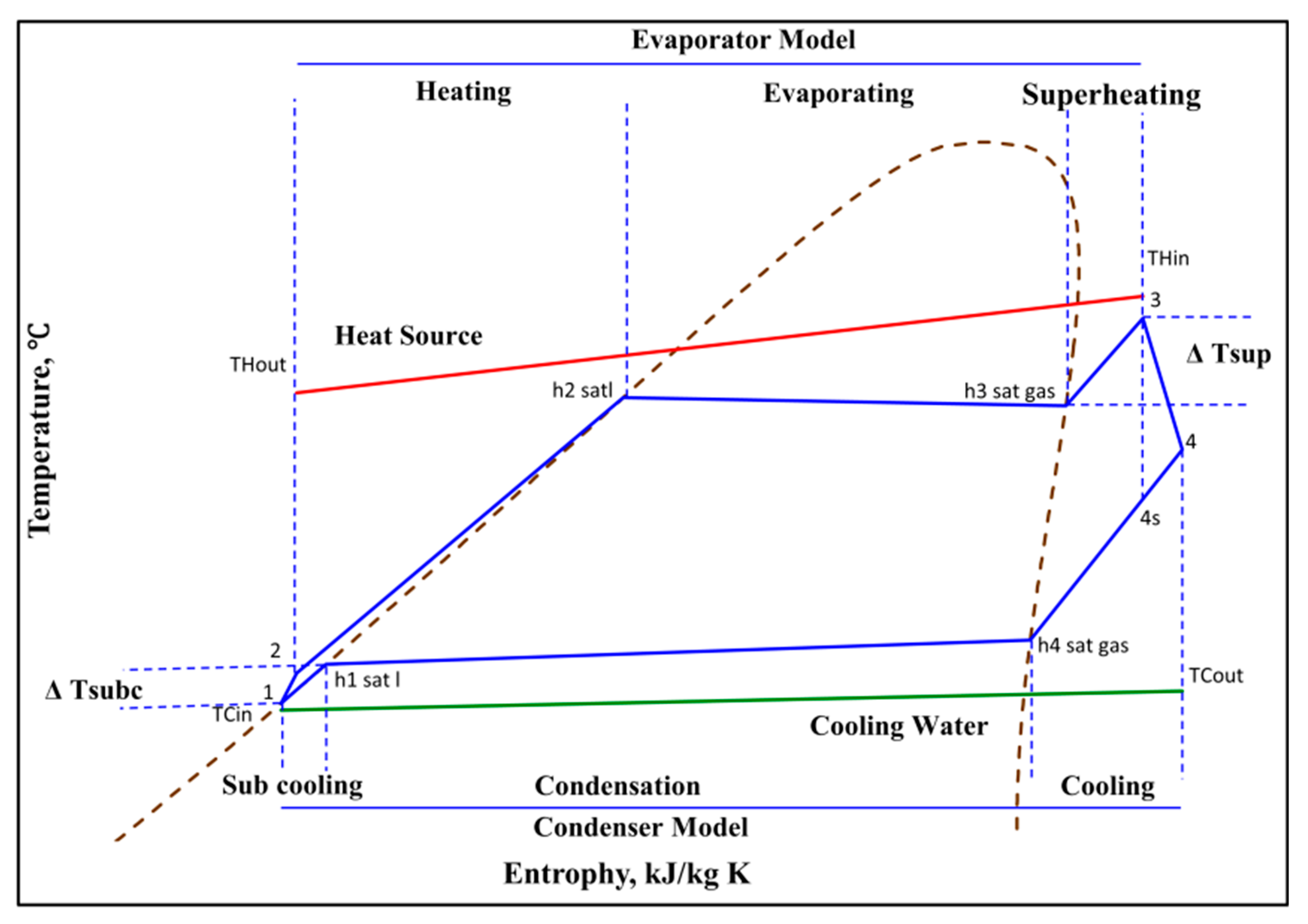
A T-s chart of the thermodynamic cycle is presented in
Figure 3, which demonstrates the fundamental process and heat transfer of the ORC system. Thermodynamic analysis based on experimental parameter data became the main way to find out the binary cycle performance which has been constructed. The thermodynamic analysis consisted of mass conservation, energy conservation, and the second law of thermodynamics. All the analysis would be applied to binary cycle components, which consisted of a piston pump, evaporator PHE, scroll-type expander, and condenser PHE.
Working fluid R123 in phase liquid at state 1 flowed in the piston pump and was compressed isentropically to the operating pressure of an evaporator at state 2. The piston pump worked without heat transfer surrounding it. The conversion of energy relation for the piston pump could be expressed as follows:
The entrances and exits of the piston pump are indicated by enthalpy h1 and h2, respectively, whose values depend on temperature and pressure; meanwhile, the mass flow rate is indicated by , which streams to the whole system.
Working fluid in compression flowed throughout the evaporator from state 2 to state 3. Inside the evaporator, a heat transfer process had occurred, in which conductive oil infiltrated heat energy to the working fluid R123. The evaporator heat transfer coefficient could be calculated by the logarithmic mean temperature difference (LMTD) method. The evaporator heat transfer (Q
evap), LMTD (ΔT
evap), and heat transfer coefficient (U
evap) could be expressed as follows:
The pinch point is located in the heat exchanger, where the temperature difference between the hot and cold fluid is the smallest at that location. The pinch points are important for analysing heat transfer in the thermodynamic cycle and are presented as follows:
Pump power consumption has a lower proportion in theory when compared to electricity output. In order to find out the portion of the electricity output to drive the pump, Lei et al., 2016 [
49], Miao et al., 2015 [
50], Yang et al., 2015 [
51], and Quoilin, et al., 2013 [
52] revealed that the Back Work Ratio (BWR) to represent the fraction between the energy consumed by the pump and the electrical energy produced, can be written as:
The temperature difference of superheating (ΔTsup) at the discharge side of the evaporator (state 3) had high temperature and pressure, and flowed in through the scroll-type expander, which expanded to produce power output and discharge to the entrance of the condenser (state 4). The scroll expander power output (
Wt) could be written:
Meanwhile, the ideal isentropic expansion is from 3 to 4s, whereas the real one is from 3 to 4; therefore, the expander isentropic efficiency (η
is, exp) could be expressed as follows:
The ORC efficiency could be described as:
4. Discussion
Differential experimental data were obtained during the test and steady-state operation was focused on first. Thermodynamic parameters consisting of pressure, temperature, and other experimental data will be discussed, which illustrate the characteristics of comprehensive operation for the working fluid R123, while a further investigation on the binary cycle system performance was explored completely.
4.1. Data for Thermodynamic Condition in Steady-State Operation
In order to investigate working fluid R123, the heat source temperature at the inlet evaporator was fixed at 120 °C. The axial pump is utilised to circulate the conductor oil, which can be controlled to adjust the mass flow rate in the evaporator. The condition of conductive oil flows to the evaporator has a constant speed by setting the frequency to 55 Hz on the axial pump and all experiment data are taken under these conditions.
The circulating cooling system with cooling water mass flow rate between 3.00 and 3.17 Kg/s utilises an axial pump. The ambient weather affects temperature fluctuation in cooling towers, especially when utilising a cooling tower which is placed on top of a building. Temperature fluctuation in the cooling tower constituted the main factor which affects condenser performance. Therefore, a needle valve is installed to adjust the valve opening so that the effect of the mass flow rate on the cooling cycle can be controlled.
In collecting research data, the mass flow rates of working fluid are increased gradually by adjusting the frequency speed of the piston pump. Differential changes were determined on the value of superheating at the inlet of the scroll expander 278, 280, 282, 284, and 286 K. Every thermodynamic condition, such as variety of pressure, transforming of temperature, and rotational speed of scroll expander, will be particularly controlled by the mass flow rate of working fluid and heat source temperature.
Firstly, with the recorded data, the heat source temperature was within a lower fluctuation, ranging from −0.5 to 0.5 °C. In each position, experiments were maintained, in any case, for at least 20 min of steady-state for data recording, to assess system performance. The experiment data were logged when the flow rate and temperature of the heat source were constant, which were recorded 12 times in one minute with an interval period of about 420 min, so that there were 240 experimental data.
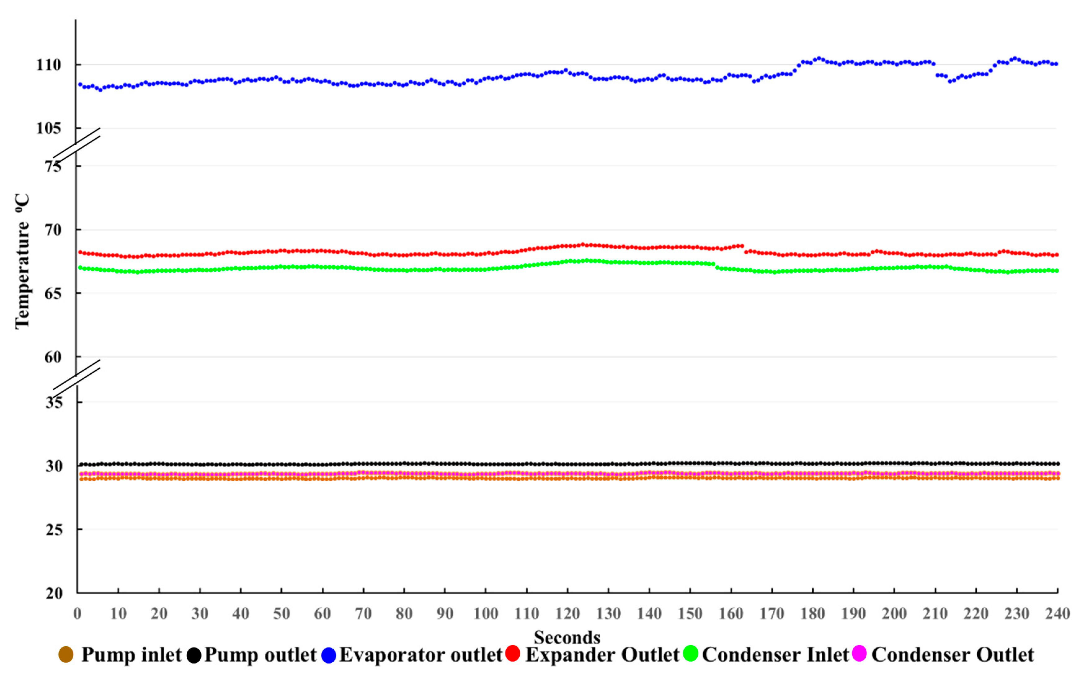
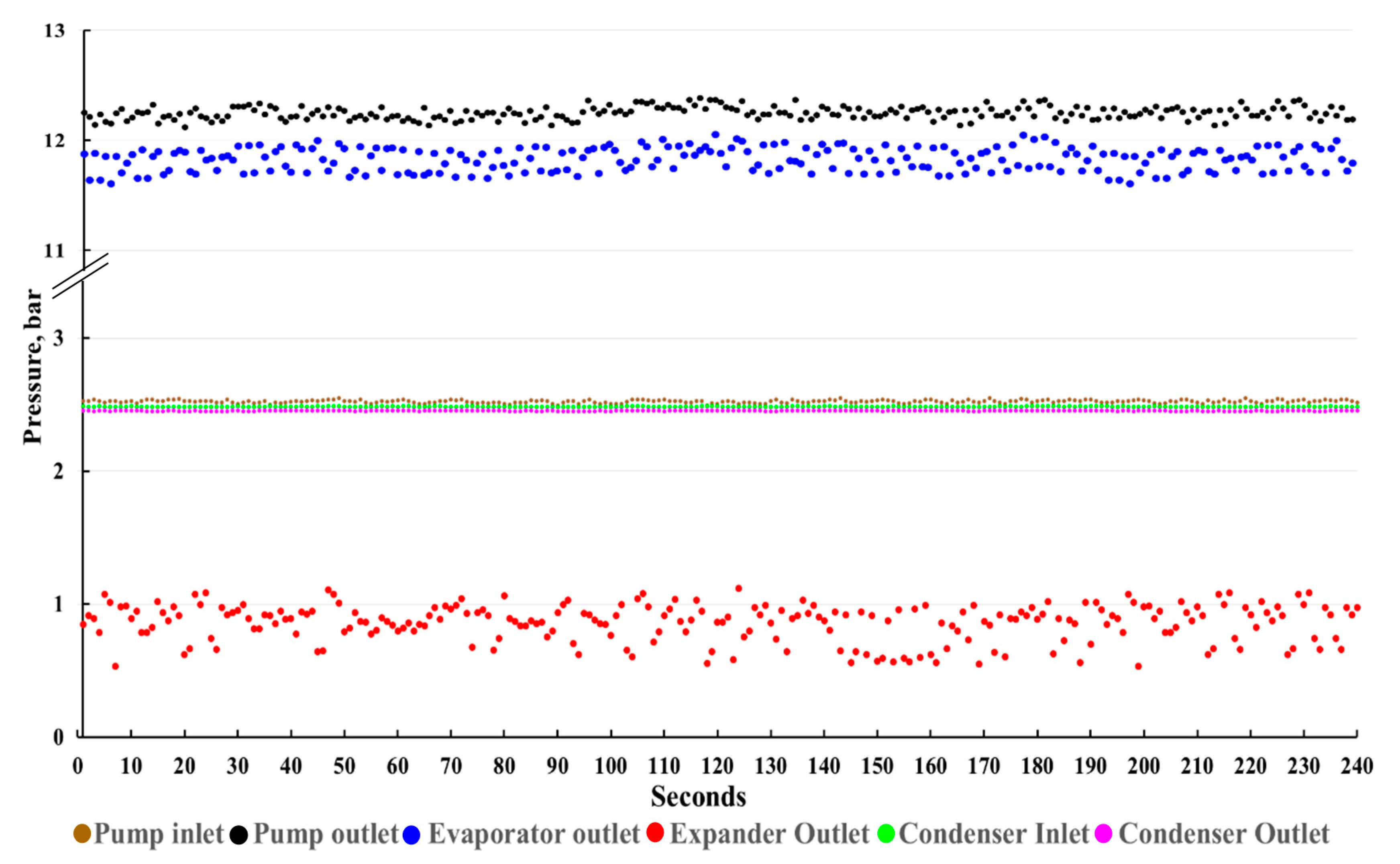
The detailed experiment data with specific superheat vapour at 278 K and heat source temperature of 120 °C are presented in
Figure 4, which shows temperature data and
Figure 5 which shows pressure data at the pump inlet, pump outlet, evaporator outlet, expander outlet, condenser inlet, and condenser outlet. All data were calculated to further assess the steady-state experiment operation. Within 20 min of stable operation, the pump inlet and condenser outlet showed coincident and very precise temperatures with no significant changes. This situation was caused when, in the condenser, which acts as a heat exchanger for heat release, the working fluid released its heat energy into the cooling water; after that, it went to the inlet pump so that at the condenser outlet point, the temperature showed almost the same temperature as the pump inlet, as seen in
Figure 4. As observed in
Figure 4, the temperature at the pump outlet indicated greatly stable operation, contrary to the evaporator outlet, expander inlet, and condenser inlet, which displayed slight fluctuation in operation.
The variation of pressure in
Figure 5 illustrates the data of four main components which operate in the experiment as a unified whole system. The pressure at the expander outlet, condenser inlet, and condenser outlet revealed a constant reading over the span of the experiment period. The opposite condition was observed at the point of the pump inlet, pump outlet, and evaporator outlet, where at that point, the data have fluctuated greatly. The pump inlet recorded data from 2.49 to 2.54 bar, while the pump outlet and evaporator outlet have shown values of 12.13 to 12.38 bar and 11.60 to 12.03 bar, respectively.
4.2. Operation Characteristic of ORC System
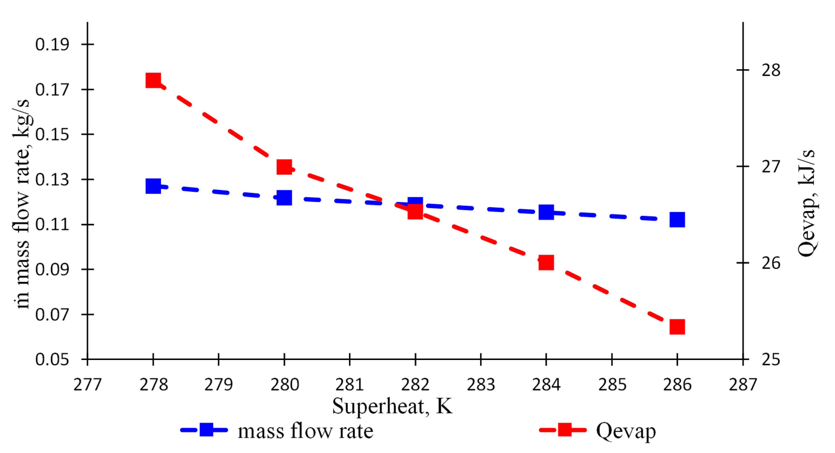
The variation of mass flow rate and evaporator heat transfer rate with superheated vapour is shown in
Figure 6. The mass flow rate, indicated in blue, decreased slightly over the span of the superheated vapour variation; at the same time, evaporator heat transfer, indicated in red, declined significantly. The degree of superheated vapour was decided by 278, 280, 282, 284, and 286 K, which produced mass flow rate of 0.127, 0.122, 0.119, 0.115, and 0.112 kg/s, respectively; meanwhile, evaporator heat rate was generated of 27.89, 26.99, 26.53, 26, and 25.34 kJ/s, respectively. An increase in the degree of superheated vapour allows for lower mass flow rate or a lower speed, signifying that the working fluid R123 streamed inside the evaporator for longer and received heat energy for a longer time from heat source. Nevertheless, the evaporator heat transfer rate did not show an increasing trend, as the amount of heat energy was not determined by the interacting duration of the working fluid with the heat source, but was influenced by mass flow rates. This component, if multiplied by enthalpy, would produce an evaporator heat transfer rate.
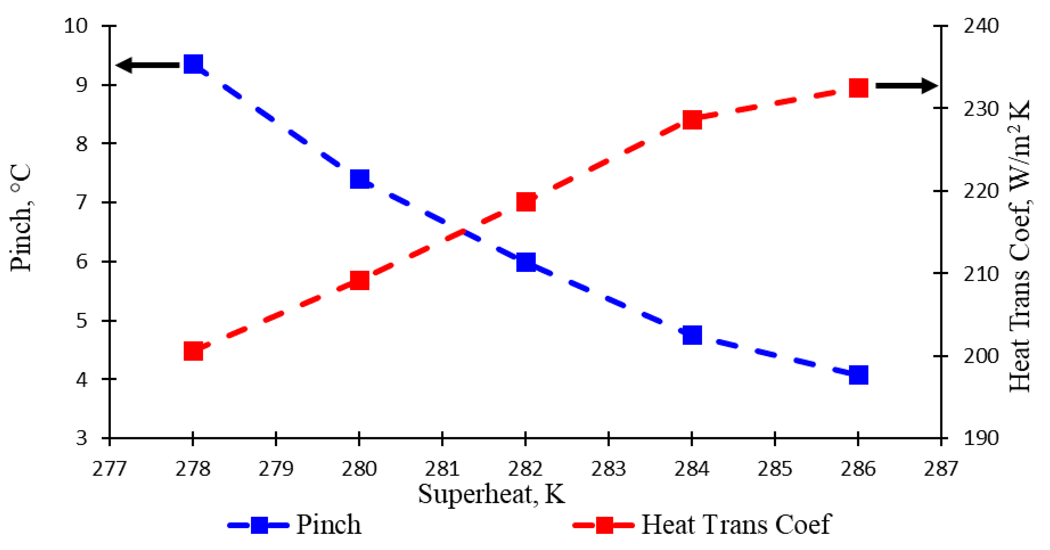
The lowest temperature difference between the two composite curves is known as the pinch point, such as in a heat exchanger. The size of the pinch point expresses high thermal losses caused by external irreversibility. The waste work potential or the lost opportunity to do work in thermodynamic analysis can be called irreversibility.
Figure 7 demonstrates the changes in pinch points and evaporator heat transfer coefficients for a variety increases in superheated vapour degree. The line indicated with blue colour shows the pinch point, which declined gradually during the span of the experiment. This condition was clearly acceptable due to the superheated vapour and pinch points being always in opposite positions. Therefore, when the superheated vapour temperature was small or equal to 278 K, the temperature of the pinch point was the largest or equal to 9.35 °C, and vice versa; when the superheated vapour temperature was greater or equal to 286 K, the pinch point temperature would be smaller or 4.08 °C. Moreover, if the superheated vapour temperature increased, it would result in smaller irreversibility because the pinch point became smaller.
Meanwhile, it can be seen that with the increase in superheated vapour, the heat transfer coefficients for working fluid R123 have a similar behaviour of climbing—a rather steep hill and slope. Conversely, R123 increases gradually first, from 200.62 W/m
2 K at superheated vapour 278 K to 228.73 W/m
2 K at superheated vapour 284 K and then, tends to slope of 232.54 W/m
2 K at superheated vapour 286 K. This is caused by the decreasing evaporator heat transfer rate, which is due to less power being captured for ensuring the decline mass flow rate, as shown in
Figure 6. However, when an evaporator heat transfer coefficient is the highest grade, the irreversibility has the lowest grade, which means less wasted heat.
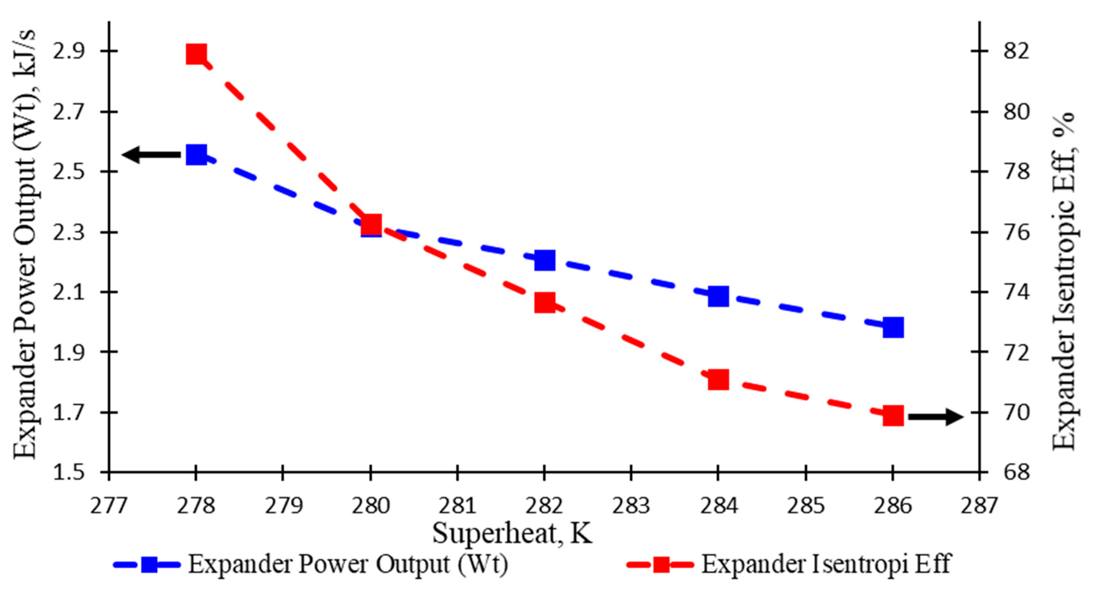
Figure 8 illustrates the effect of variation in the degree of superheated vapour on expander behaviour. As observed, the expander power output, which is indicated by the blue colour, slumped gradually with the range 1.98 to 2.56 kW over the span of the experiment. Similarly, expander isentropic efficiency, which is indicated by the red colour, yields a sharp decreased trend with the range from 69.93% to 81.91% in the retrieval of data during the experiment. Increasing the superheated vapour degree is usually done by adding a heat input in the evaporator; therefore, both the network and heat input increase as a result of superheating the vapour to a higher temperature, as revealed in the thermodynamic fundamental. On the other hand, as seen in
Figure 8, there is a sufficient decrease caused by a shrink in mass flow rate. The experiment with determined superheated vapour values of 278, 280, 282, 284, and 286 K, has resulted expander power outputs of 2.56, 2.32, 2.21, 2.10, and 1.98 kW, respectively, and then, produced expander isentropic efficiencies of 81.91%, 76.27%, 73.68%, 71.09%, and 69.93%, respectively.
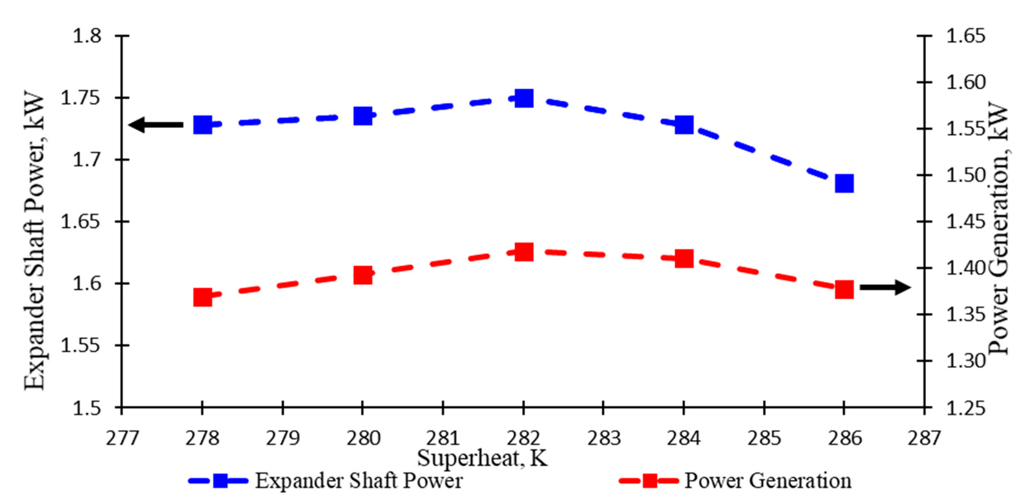
The graph in
Figure 9 presents a variation in temperature of the superheated vapour that affected expander shaft power (indicated in blue) and power generation (indicated in red). Both display a uniform trend, which nearly remained unchanged from the superheated vapour 278 K until 282 K. At this point, both started to show a small decline in superheated vapour at 284 K and continued to deeply drop until the last experiment. As observed, the increase in superheated vapour has no effect on the expander shaft power, especially during the range temperature of superheated vapour from 278 to 282 K. However, with the further derivation in mass flow rate (as revealed in
Figure 6), the expander work output decreased deeper (as revealed in
Figure 8) and showed an effect of expander shaft power for going down during the range temperature of superheated vapour from 284 to 286 K. When comparing expander work output in
Figure 8 and expander shaft power in
Figure 9, they should have the same trend, but the results of the experiment are relatively different. This is possibly influenced by the machinery mechanism and using generator equipment. The experiment with determined superheated vapour values of 278, 280, 282, 284, and 286 K has resulted in expander shaft power of 1.729, 1.736, 1.75, 1.73, and 1.168 kW, respectively, and then, produced power generation of 1.37, 1.39, 1.42, 1.41, and 1.37 kW, respectively.
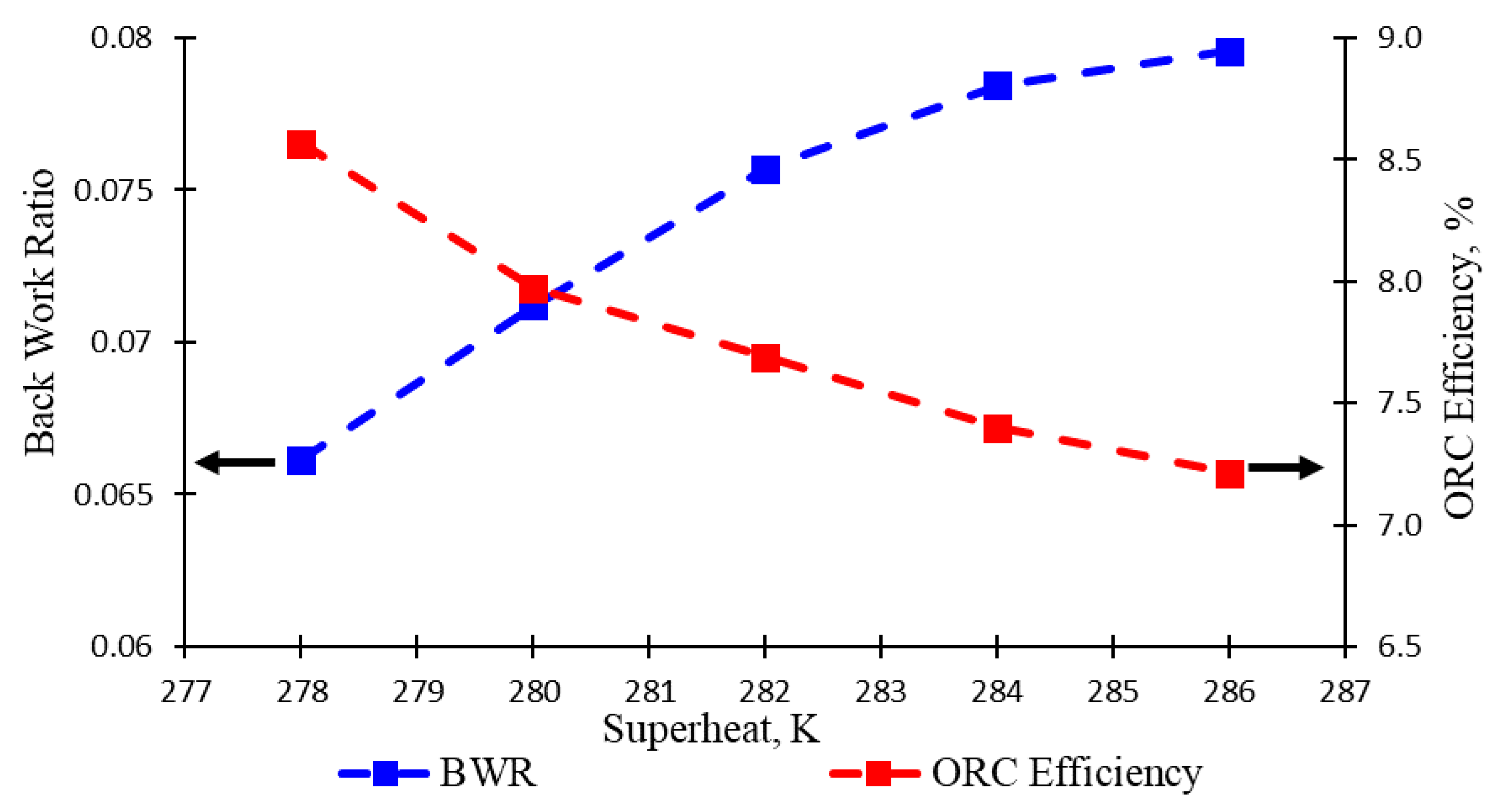
The illustration in
Figure 10 informs the difference in degree of the superheated vapour, which affects system overall performance, namely back work ratio (BWR) and ORC efficiency. Both are, indeed, ways to reveal whether the system as a whole has the best performance. Consequently, BWR at a lower value is better than a high value, whereas ORC efficiency is vice versa. BWR (indicated in blue) and ORC efficiency (indicated in red) have a uniform tendency in the opposite direction. Starting with the exact value of 0.066, BWR constantly increased with a small degree of curve during the span of the experiment. Absolutely, ORC efficiency decreased with slope curve over the interval in degree of the superheated vapour. The experiment with determined superheated vapour values of 278, 280, 282, 284, and 286 K has resulted back work ratios of 0.066, 0.071, 0.075, 0.078, and 0.079, respectively, and then, produced ORC efficiencies of 8.6%, 8.0%, 7.7%, 7.4%, and 7.2%, respectively.
As observed in
Figure 6 and
Figure 8, ORC efficiency was affected by evaporator heat transfer rate and expander power output. Increasing the degree of superheated vapour enabled lower evaporator heat transfer rate and lower expander work output, and simultaneously, the evaporator heat transfer rate decreased faster than the evaporator work output, which resulted in the decrease in ORC efficiency.

 ,
, 


