
A New Conservative Hyperchaotic System-Based Image Symmetric Encryption Scheme with DNA Coding

1
Hunan Police Academy, Changsha 410138, China
2
School of Computer Science and Engineering, Central South University, Changsha 410083, China
3
South Campus, Changsha Normal University, Changsha 410100, China
*
Author to whom correspondence should be addressed.
Symmetry 2021, 13(12), 2317; https://0-doi-org.brum.beds.ac.uk/10.3390/sym13122317
Submission received: 11 November 2021
/
Revised: 26 November 2021
/
Accepted: 1 December 2021
/
Published: 4 December 2021
(This article belongs to the Special Issue Chaotic Systems and Nonlinear Dynamics)
Abstract
:In the current paper, a new conservative hyperchaotic system is proposed. We make a quantitative analysis of the complexity of the conservative hyperchaotic system from several different aspects, such as phase diagrams, bifurcation diagrams, Lyapunov exponents, and Kaplan–Yorke dimension. The complexity of chaotic time series is tested with various measurement tools, such as the scale index, the multiscale sample entropy and approximate entropy, TESTU01, and NIST test. In addition, a novel hyperchao-based image encryption scheme with dynamic DNA coding is proposed. The encryption algorithm consists of line-by-line scrambling and diffusion of DNA encoding characters. The dynamic DNA coding mechanism is introduced by using the chaotic sequence. The generation of the intermediate secret keys is related to the sum of the image DNA code, and the ciphertext feedback mechanism of the DNA encoding image is introduced in the diffusion procedure. Simulation experiments and various security analyses show that this algorithm has a good effect on encryption, high time efficiency, and can effectively resist brute force attacks, statistical attacks, chosen-plaintext attacks, and differential attacks.
1. Introduction
With the rapid development of the Internet and the rapid expansion of information, a large amount of information is transmitted through public channels. Information security has become one of the key issues in the modern network communication era [1]. There are many types of information data, such as text, language, image, video, etc., among which images are the most widely used in information transmission [2]. The secure exchange of image information has attracted the attention of many researchers. Among various image information security technologies, image encryption occupies an important position. In the field of information encryption technology, cryptographers have proposed many encryption methods, such as data encryption standard (DES), advanced encryption standard (AES), RSA, international data encryption algorithm (IDEA), and other algorithms [3]. However, these traditional encryption methods are suitable for encrypting data with small amounts of information, such as text and small amounts of data. Image data have a different nature from text and small data. The image has a large amount of data and high information redundancy. Therefore, traditional encryption algorithms are not suitable for image information encryption [4]. This paper proposes an image encryption algorithm based on a new chaotic system and dynamic DNA (deoxyribonucleic acid) coding.
Latterly, chaotic systems have been widely adopted in the territory of encryption, especially in image encryption [5,6]. For example, in the medical field, in order to protect the privacy of patient information, it is often necessary to encrypt medical images. In [7], the authors proposed a fast and secure lightweight image encryption algorithm using the chaotic system. The signal generated by the chaotic system is sensitive to the initial value, pseudo-random, ergodic, and unpredictable, which affords the chaotic system excellent performance in encryption [8,9,10]. While studying the application of chaotic systems to information encryption, people are also studying new chaotic system modeling and chaotic system performance improvement issues, some improved chaotic systems, such as the 2D logistic-sine-coupling map [11], the improved Chebyshev map [12], have excellent performance in the field of encryption. In the category of continuous-time chaotic systems, there are two types: dissipative chaotic systems and conservative chaotic systems.
At present, most of the existing digital image encryption schemes use dissipative chaotic systems. However, compared with the conservative chaotic system, the dissipative chaotic system has an attractor, so the attacker can reconfiguration the chaotic system by rebuilding the attractor. On the other hand, there are no attractors with a conservative chaotic system, thus the opponent cannot decode the encryption algorithm by rebuilding the chaotic system used in the encryption algorithm, which can greatly promote the security and soundness of the encryption scheme. Therefore, conservative chaotic systems may be more fit for chaos-based information encryption systems and have attracted researchers’ attention [13,14].
DNA (deoxyribonucleic acid) computing is a new generation of computing technology that uses biochemical reaction technology to use biological DNA molecules as information carriers instead of standard artificial hardware for computing. Compared with traditional computing, DNA computing has some potential advantages, such as huge storage space, massive parallelism, and ultra-low power consumption [15], therefore, it has attracted the attention of many researchers in different fields such as mathematics, biology, and computer science [16,17]. Among them, some researchers have introduced the concept of DNA computing into cryptography and used its calculation rules as part of the encryption algorithm. The subject of studying such kinds of encryption algorithms is called DNA cryptography [18]. The introduction of DNA encoding schemes into the field of image encryption is based on the method of processing information in biological sciences [19,20,21]. Using the DNA coding scheme to process digital images, the pixel position and pixel value of the image can be changed at the same time to achieve a good encryption effect [22,23]. Combining the chaotic system to realize the random and dynamic change of the DNA coding rules is an effective means to better the security of the encryption system. At present, many image encryption algorithms based on DNA encoding have been proposed [24,25,26,27]. In [28], Zhang et al. proposed a novel image fusion encryption algorithm based on DNA sequence operation and hyper-chaotic system. In 2015, Song et al. [29] proposed an image encryption algorithm based on DNA encoding and spatiotemporal chaos (IEA-DESC). In [30], Wang et al. proposed a novel and effective image encryption algorithm based on chaos and DNA encoding. In [31], Hu et al. proposed an image encryption scheme combining chaos with cycle operation for DNA sequences, in the scheme, the DNA coding rule was controlled by a keystream produced from Chen’s hyper-chaotic system. In [32], Yong Zhang proposed an image encryption algorithm based on chaos and DNA computing. He proved that the DNA of the image represented the existence of 24 DNA coding rules and proposed a new DNA connection operation. Recently, Yan et al. [33] proposed a chaos-based image encryption algorithm by using an arithmetic sequence scrambling model and DNA coding. However, some methods have been proven to have serious defects and are vulnerable to chosen-plaintext attacks. For example, the encryption algorithm proposed in [29] was broken by Wen et al. [34] using a chosen-plaintext attack and a chosen-ciphertext attack, respectively. The encryption algorithm proposed in [28] was broken by several researchers using chosen-plaintext attacks [35,36,37]. Some image encryption algorithms based on DNA encoding have high time complexity and cannot meet real-time encryption requirements [25,30,31].
Recently, Hybrid encryption technology has attracted researchers’ attention. Fawad Masood et al. [38] proposed a hybrid technique, say, MT-DNA-Chaos based novel image encryption algorithm In [39], the authors proposed a novel image encryption algorithm based on a Julia set of fractals and three-dimensional Lorenz chaotic system. The above methods expand the technical scope of image encryption and have various characteristics.
In the field of cryptology, another research direction parallel to cryptography is cryptanalysis. At present, some cryptanalysis [40,41,42] studies show that some image encryption algorithms based on chaos have security defects, which can be summarized as follows: the secret keyspace is insufficient and can not resist exhaustive attacks. The distribution of ciphertext is not uniform enough, leaving loopholes for statistical analysis attacks. The equivalent secret key of the cryptosystem does not change with the encrypted content, and the algorithm can not resist the selective plaintext attack. In order to overcome some shortcomings of the chaos-based image encryption algorithm, in this work, we put forward an image encryption algorithm based on a new conservative hyperchaotic system and dynamic DNA coding. The encryption algorithm consists of two main processes: one is the line-by-line scrambling for DNA encoding image, the other is diffusion and encryption of the scrambled DNA encoding image. The main contributions of this work are as follows:
- (1)
- A new conservative hyperchaotic system is established, and the complexity of the system is analyzed by using a variety of measures. It is proven that the system has good hyperchaotic characteristics.
- (2)
- A novel hyperchaos-based image encryption scheme with dynamic DNA coding is proposed. The system consists of the line-by-line scrambling process and diffusion is achieved using a DNA encoding scheme.
- (3)
- Some statistical analyses and comparative analyses are also performed for the evaluation of the image encryption algorithm. It is verified that the proposed encryption algorithm has better cryptographic performance.
The rest of this paper is organized as follows: Section 2 introduces the new conservative chaotic system, image DNA coding, and operating rules. Section 3 provides details of the proposed image encryption and decryption algorithm. Section 4 shows the results of simulation experiments. Section 5 highlights the conclusion of this paper.
2. Preliminary Works
2.1. The 4D Conservative Hyper-Chaotic System
Continuous-time dynamical systems described by mathematical model are divided into three types: dissipative, conservative, and expanding in phase-volume depending on the sign of the divergence, ∇·f < 0, ∇·f = 0, and ∇·f > 0, respectively, where ∇ is the Hamilton operator, and f is the vector function of the dynamical system.
Due to the ∇·f < 0 property of dissipative systems, their steady-state solutions are attractors. They can be nodes, stars, focal points, limit cycles, quasi-periodic and chaotic attractors. Since the phase space is close to zero, the dimension of the dissipative chaotic system is fractional, which leads to poor ergodicity because the trajectory reaches the zero-volume space and the initial entry trajectory does not occupy a huge space.
In contrast, because of the property of ∇·f = 0 for the conservative systems, the volume of phase space of a conservative system is conserved, and it can show concentric periodic solutions, quasi-periodic solutions, and chaotic solutions, but these are not attractors. On this account, a conservative system has better ergodicity than a dissipative system. Compared with dissipative chaotic systems, conservative chaotic systems can produce more complex pseudo-random numbers.
Inspired by reference [43], we propose a 4D conservative hyper-chaotic system model. The proposed system is described mathematically by Formula (1).
In Equation (1), a, b, c are the system parameters, [x0, y0, z0, w0]T are initial state values of the system variables. The divergences of f = [f1, f2, f3, f4]T for system (1) is:
Therefore, the phase space volume of system (1) is conservative.
If the parameters and initial state values are set appropriately, then the conservative system (1) will be chaotic. Take parameters [a, b, c]T = [12, 8, 8]T, initial conditions [x0, y0, z0, w0]T = [1, 1.1, 3.2, 3.3]T, and sampling time step Δt = 0.01 s from t = 0 to t = 1200. The orbits of system (1) is chaotic (Figure 1a–f), which can be verified by the Lyapunov exponents [L1, L2, L3, L4]T = [0.004260, 0.005551, −0.002850, −0.006961]T. The sum of the Lyapunov exponents is (L1 + L2 + L3 + L4) = 0. The Kaplan–Yorke dimension based on the mentioned Lyapunov exponents is
The Kaplan–Yorke dimension is an integer and equals the system dimension. Next, we make a quantitative analysis of the complexity of system (1) from several different aspects.
2.1.1. Lyapunov Exponent Curve and Bifurcation Chart
Figure 2 shows the Lyapunov exponent spectrum and bifurcation diagrams of system (1). From Figure 2 one can see that the positive and negative Lyapunov exponents are symmetric about zero and the sum of the total Lyapunov exponents is zero. Therefore, system (1) is a conservative chaotic system (CCS). In addition, there are two positive Lyapunov exponents (L1 and L2 of Figure 2) in system (1), so the conservative chaotic system is in the hyperchaotic state. We find that the system has hyperchaotic characteristics in the experimental parameter range, but it is not limited to the above parameter range. Further research can find other parameter ranges that make the system produce chaotic behavior. In addition, two Lyuponov exponents are symmetric, that is, L1 and L4 are symmetrical, L2 and L3 are symmetrical.
2.1.2. The Scale Index
In addition, there are some other methods that can be used to test the complexity of chaotic time series. For example, in [44], the authors adopted the scale index which is presented by Benítez et al. [45] to detect and study non-periodicity in the chaotic sequences. The scale index technique is based on the continuous wavelet transform and multi-resolution analysis technology. Here, the computations are performed using the R statistical software named wavScalogram developed by Vicente J. Bolós et al. [46], which provides a convenient means for researchers to identify the aperiodic features of time series.. Starting with the initial condition (x0, y0, z0, w0) = [2, 2, 2, 2]T, we iterate the system (1) 4595 times with the time step Δt = 0.01, obtain four sequences of {x1, x2, x3, x4} each with a length of 4596. Discard the first 500 values for each sequence, then synthesize them into a sequence x = [x1, x2, x3, x4] with a length of 16,384, and then convert the synthesized sequence into an integer sequence Intx = mod(floor(x × 1012), 256). Then, calculate the scale index values of the sequence Intx. Some representative results are shown in Figure 3. Comparing Figure 2a and Figure 3a, we find that when a changes from 11.3 to 13, the scale index at the largest scale 4096 increases from 0.4146713 to 0.4257676, which is consistent with the increase in Lyapunov exponent in Figure 2a. Comparing Figure 2b and Figure 3b, we find that when b changes from 9 to 10, the scale index at the largest scale 4096 increases from 0.7163966 to 0.9804939, which is consistent with the increase in Lyapunov exponent in Figure 2b. Comparing Figure 2c and Figure 3c, we find that when c changes from 8 to 9, the scale index at the largest scale 4096 increases from 0.4502245 to 0.6935807, which is consistent with the increase of Lyapunov exponent in Figure 2c. Figure 3d shows the scale index of the sequences generated by the famous chaotic logistic map and the proposed CCS, we find that the scale index at the largest scale 4096 of the proposed CCS is larger than that of the logistic map.
2.1.3. The Multiscale Sample Entropy and Approximate Entropy
Multiscale sample entropy (MsEn) is used to describe the degree of irregularity of time series at different scales, including parameters m, s, and τ. Where m is the embedding dimension, s is the similarity coefficient and τ is the scale factor. Approximate entropy (ApEn) involves two parameters m and r. Where m is an integer, representing the length of the comparison vector, and r is a real number, representing the measure of “similarity”. Set the parameters of system (1) as a = 12, b = 8, and c = 8. The initial state values are set as x0 = 1.0, y0 = 1.1, z0 = 3.2, and w0 = 3.3. Use the Runge–Kuda algorithm to solve the differential equation of system (1), the time step is set to 0.001, generate four chaotic sequences of length 6000, and remove the first 500 values in front of each sequence, obtain four sequences x1, x2, x3, x4, each of them has the length of 5500 real numbers. Connect the four sequences to obtain a real number sequence X = [x1, x2, x3, x4] with a length of 22,000. In the test, five groups of parameters are taken to calculate the MsEn of sequence X, and the results are shown in Table 1.
Similarly, five groups of parameters are taken to calculate the ApEn of sequence X, and the results are shown in Table 2.
2.1.4. TESTU01 Test
TestU01 is a well-known software for testing the performance of random number generators (RNGs). The test data source of the software can be a predefined generator in the instance library of the software, a user-defined generator, or even a data file generated by equipment or software. This paper only focuses on the predefined batteries of tests available in TestU01 for the binary bit test. The bit sequences test in TestU01, namely, Rabbit, Alphabit, and BlockAlphabit, which are carried out by the following functions:
- (1)
- Void bbattery_RabbitFile(char *filename, double nb);
- (2)
- This function applies the Rabbit battery of tests to the first nb bits (or less, if nb is too large) of the binary file filename. For each test, the file is reset and the test is applied to the bit stream starting at the beginning of the file.
- (3)
- Void bbattery_AlphabitFile(char *filename, double nb);
- (4)
- This function applies the Alphabit battery of tests to the first nb bits (or less, if nb is too large) of the binary file filename.
- (5)
- Void bbattery_BlockAlphabitFile(char *filename, double nb);
This function applies the Alphabit battery of tests repeatedly to the binary file filename.
Their design function is to test the complexity of the finite bit sequence stored in binary files. For the three tests, a binary sequence with a length of 2 × 107 bits is produced by using the CCS system (1) and saved as a data file. In the Rabbit test, we adopted 1,048,576 bits and 6,000,000 bits from the binary file to test, respectively. The summary results of the test of Rabbit are shown in Table 3, which confirmed that each test is passed with a p-value in the range of [0.001, 0.9990].
In the Alphabit test, we adopted 1,048,576 bits from the binary file to test. The results are shown in Table 4, which confirmed that all tests were passed with a p-value in the range of [0.001, 0.9990].
In the BlockAlphabit test, we obtain six identical results, as shown in Figure 4. The conclusion is “All tests were passed”.
2.1.5. NIST Test
NIST is a standard test software package released by the National Institute of Standards and Technology to evaluate the random performance of series, which includes 15 test indexes. Usually, the NIST test requires multi sequences and each one has 1,000,000 bits. NIST test software mainly uses two performance indicators: p-value and pass rate to determine the random nature of a sequence. The default p-value threshold is 0.01. If the p-value is greater than this threshold, the test is considered to have passed. We generated 10 sequences and each one has 1,000,000 bits, then the NIST test is performed. The results from all statistical tests are given in Table 5.
In Table 5, the minimum pass rate is 7 samples for the random excursion and its variant test of 8 binary sequence samples. For 20 binary sequence samples, the minimum pass rate of all kinds of statistical tests is 18 samples, except for random excursion and its variant.
2.2. DNA Coding and Operations
DNA contains four kinds of bases, namely A (adenine), T (thymine), C (cytosine), and G (guanine). Traditional computer processing of data is usually expressed in binary form of 0 and 1. If a 2-bit binary number is used to represent a DNA base, there are 24 different representation methods in total. Based on the law of base complementary pairing, A and T are complementary, and C and G are complementary, so there are 8 kinds of expressions that conform to the principle, called eight kinds of DNA coding rules, as shown in Table 6. For a gray image with 256 gray levels, each pixel value is an 8-bit binary number and can be encoded as a DNA sequence with a length of 4. The DNA encoding process can be implemented by defining a function DNAencode(value, rule). For example, the pixel value 228 (its binary form is 11100100) can be encoded as a DNA sequence “TCGA” by using the coding rule 1, namely, DNAencode(228, 1) outputs the result of “TCGA”. Conversely, a 4-character DNA string can be decoded as an 8-bit binary integer, which has a decimal value that is greater than or equal to 0 and less than or equal to 255, and the decoding process can be implemented with a function, e.g., DNAdecode(strDNA, rule). For instance, DNAdecode(“TCGA”, 7) outputs the binary form 00100111, which is the decimal number 39. It can be seen from this example that the pixel value 228 is encoded by rule 1 and then decoded by rule 7 to output a pixel value of 39. That is to say, after encoding the pixel value into a DNA code with a certain rule number, and then decoding it with a different rule number, the pixel value obtained is very different from the original pixel value. thus, we can use this feature of DNA encoding and decoding to realize image encryption.
In addition to DNA coding rules, we introduce three DNA operations: DNA addition, DNA subtraction, and DNA XOR, based on binary calculations. We regard A, C, G, and T as the numbers 0, 1, 2, 3, respectively, so the addition, subtraction, and XOR operations of DNA symbols can be executed according to the numerical calculation rules, and then the numerical results are expressed as characters. Thus, we obtain the three DNA operation rules as shown in Table 7, Table 8 and Table 9 respectively. The DNA XOR operation has the following rules, that is, if z = DNAXOR(x, y), then x = DNAXOR(z, y) or y = DNAXOR(z, x). DNAADD operation and DNASUB operation are inverse operations, that is, if z = DNAADD(x, y), then x = DNASUB(z, y) or y = DNASUB(z, x).
3. Image Encryption and Decryption Algorithm
Notation description: Bold regular letters, such as P and C, indicate matrices or vectors. Non-bold italic letters, such as x and P(i), indicate scalar variables or array elements. Non-bold regular letters, such as M and N, indicate scalar constants.
3.1. The Encryption Algorithm
The image encryption algorithm mainly includes the following five stages: (1) Generate chaotic sequence. (2) Image DNA encoding. (3) Implementation of line-by-line scrambling for DNA encoding image. (4) Diffusion and encryption of DNA encoding characters. (5) DNA decoding to obtain ciphertext image. In stage (1), the initial values (x0, y0, z0, w0) and the system parameters (a, b, c) are input, and the conservative hyper-chaotic system is iterated to generate four chaotic sequences {x, y, z, w}, each of which has a length of L (L is the total number of pixels contained in the image to be encrypted); then, the four chaotic sequences are connected to form a chaotic sequence X with a length of 4L; finally, the chaotic real number sequence X is converted to an integer sequence IntX. In stage (2), the original image is encoded with coding rule r1 according to Table 1 to generate the DNA coding image. In stage (3), index scrambling is performed to change the DNA characters’ position for each row of the DNA coding image. In stage (4), the DNA coding image and chaos sequence are used to perform dynamic DNA operations, and the principle of DNA addition, DNA subtraction, and DNA xor are used to achieve pixel diffusion. In stage (5), DNA dynamic decoding is carried out to obtain the cipher image. The specific implementation process and steps are given in below. The block diagram of the proposed encryption algorithm can be described by Figure 5. The secret key set of the cryptosystem includes the initial values (x0, y0, z0, w0) of the conservative hyperchaotic system. In Figure 5, represents the plaintext image, represents the DNA coding image, represents the DNA coding sequence after row permutation, represents the DNA coding sequence after diffusion, and represents the final ciphertext image. and are all matrices of size M × N.
The encryption algorithm can be specifically described as follows:
Step1: Given a positive integer N0, the chaotic system iterates (N0 + M × N) times, discards the first N0 numbers, and obtains four chaotic sequences with length M × N, , , , , through the hyper-chaotic system (1) under the initial condition of {x0, y0, z0, w0} and system parameters {a, b, c}. Here, M is the number of pixel rows of the image to be encrypted, and N is its pixel column number. The purpose of introducing pre iteration number N0 is to eliminate the influence of the transient effect of the chaotic system.
Step2: Then, the four sequences are connected to form a chaotic sequence with a length of 4 × M × N.
Step3: Convert chaotic real number sequence X into integer sequence by using Equation (2):
here, i = 1, 2, …, 4 × M × N. m ∈ {6, 7, …, 15}.
Step4: For each i and j (i = 1, 2, …, M, j = 1, 2, …, N), convert every pixel value of image into a 4-character DNA string of image with rule r1(i, j) according to Table 7. The rule number r1(i, j) and the encoding process for pixel P(i, j) can be expressed by Equations (3) and (4), respectively:
Step5: Calculate the sum S0 of all character values in the DNA coded image by the following Equation (5):
Here, PC(i, j) ∊ {‘A’, ‘C’, ‘G’, ‘T’}, and ASCII(‘A’) = 65, ASCII(‘C’) = 67, ASCII(‘G’) = 71, ASCII(‘T’) = 84.
Step6: For each row i (i = 1, 2, …, M) in the DNA coded image PC, perform Step 6-1 to Step 6-4 to permutate the elements in the same row and obtain the scrambled coded image P1.
Step6-1: Calculate a position number ni according to Formula (6):
Step6-2: From position ni in the chaotic sequence X, intercept a sub-sequence, say Xi, with a length of 4N:
Step6-3: Sort the chaotic subsequence Xi to obtain a position index sequence iXi as:
Step6-4: Rearrange all the elements in the i-th row in the PC to obtain the i-th row of the scrambled image P1:
Step7: Convert the 2D image into a 1D row vector :
Step8: Initialization: P2←P1; S←S0; t←‘ACGT’; P2_1←‘G’.
Step9: For each i (i = 1, 2, …, 4 × M × N), carry out the following Step 9-1 to Step 9-6 to diffuse the DNA sequence and obtain the diffused DNA sequence .
Step9-1:S←S-P1(i);
Step9-2: According to the following Formula (10), an integer parameter ni is calculated from Intx(i) and S:
Step9-3:P2(i)←DNAadd(P1(i), P2_1);
Step9-4:P2(i)←DNAxor(P2(i), t(ni));
Step9-5:P2_1←P2(i);
Step10: For each i (i = 1, 2, …, M × N), carry out the following Step 10-1 to Step 10-2 to decode the diffused DNA sequence and obtain the decoded pixel sequence .
Step10-1: Calculate an integer r2(i) by using the following Equation (11)
r2(i) = 8-mod(Intx(i), 8)
Step10-2: Decode a 4-character DNA string with rule r2(i) to obtain an integer pixel value C1(i) by using the following Equation (12):
C1(i) = DNAdecode(P2(4 × (i − 1) + 1: 4 × i), r2(i))
Step11: Convert the one-dimensional row vector into a 2D matrix :
At this moment, the final ciphertext image C is obtained.
Compared with other simple chaotic encryption schemes, the proposed hyperchaotic encryption scheme has obvious advantages in security. For instance, the plaintext image in Arnold’s cat map can be returned by continuing the chaotic mapping from the torus into itself (i.e., order becomes chaos, and chaos becomes order again if the mapping is allowed to continue). However, compared to the simple chaotic encryption schemes, the conservative hyperchaotic system not only resists reconstruction attacks but also has richer ergodicity.
3.2. The Decryption Algorithm
The decryption algorithm can be described as follows:
Step1: Generate four chaotic arrays , , , through hyperchaotic system (1) under the initial condition of {x0, y0, z0, w0} and system parameters {a, b, c}.
Step2: Then, the four arrays are connected to form a chaotic sequence with a length of 4 × M × N.
Step3: Convert chaotic real number sequence X into integer sequence by using Equation (1).
Step4: Convert the 2D cipher image matrix into a 1D row vector :
Step5: For each i (i = 1, 2, …, M × N), carry out the following Step 5-1 to Step 5-2 to encode the pixel sequence and obtain the DNA sequence .
Step5-1: Calculate an integer r2(i) by using the previous Equation (11).
Step5-2: Encode an integer pixel value C1(i) with rule r2(i) to obtain a 4-character DNA string P2(4 × (i − 1) + 1: 4 × i) by using the following Equation (14)
P2(4 × (i − 1) + 1: 4 × i) = DNAencode(C1(i), r2(i))
Step6: Initialization: P1←P2; S←S0; t←‘ACGT’.
Step7: For each i (i = 4 × M × N, 4 × M × N−1, 4 × M × N−2, …, 3, 2), carry out the following Step 7-1 to Step 7-4 to decrypt the DNA sequence and obtain the DNA sequence .
Step7-1:P2_1←P2(i-1);
Step7-2: According to the previous Equation (10), an integer parameter ni is calculated from Intx(i) and S;
Step7-3:P2(i)←DNAxor(P2(i), t(ni));
Step7-4:P1(i)←DNAsub(P2(i), P2_1);
Step7-5:S←S + P1(i);
Step8: For i = 1, carry out the following Step 8-1 to Step 8-5 to decrypt P1(1):
Step8-1:i←1;
Step8-2:P2_1←‘G’;
Step8-2: According to the previous Equation (10), an integer parameter ni is calculated from Intx(i) and S;
Step8-3:P2(i)←DNAxor(P2(i), t(ni));
Step8-4:P1(i)←DNAsub(P2(i), P2_1);
Step8-5:S0←S + P1(i);
Step9: Convert the 1D DNA sequence into a 2D matrix .
Step10: For each i (i = 1, 2, …, M), carry out the reverse scrambling by using the following Step 10-1 to Step 10-4 and obtain the DNA coding image :
Step10-1: Calculate a position number ni according to the previous Equation (6).
Step10-2: From position ni in the chaotic sequence X, intercept a sub-sequence, say Xi, with a length of 4N by using the previous Equation (7).
Step10-3: Sort the chaotic subsequence Xi to obtain a position index sequence iXi by using the previous Equation (8).
Step10-4: Rearrange all the elements in the i-th row in the P1 to obtain the i-th row of the matrix PC by using Equation (15):
Step11: Decode the DNA coding image with rule r1(i, j) to restore the original image by using Equation (16).
Here, i = 1, 2, …, M, j = 1, 2, …, N. The rule number r1(i, j) for pixel P(i, j) can be calculated by the previous Equation (3).
4. Simulation Results and Security Analysis
To evaluate the validity of the proposed image encryption algorithm, we carried out simulation experiments with several typical gray level test images, such as lena, cameraman, baboon, peppers, which come from CVG-UGR image database (https://ccia.ugr.es/cvg/dbimagenes/g256.php (accessed on 11 November 2021)). The secret key parameters of the cryptosystem are (x0, y0, z0, w0). Use the Runge–Kuda algorithm to solve the differential equation of system (1), the time step is set to 0.001, generate four chaotic sequences of length (M × N + N0), and remove the first N0 values in front of each sequence, obtain four sequences X1, X2, X3, X4. Where, M is the row number of the test image, and N is the column number of it. N0 is a positive integer to be set. In our simulation tests, the secret key parameters are set as x0 =1.0, y0 = 1.1, z0 = 3.2, w0 = 3.3. The other parameters are set as follows: a = 12, b = 8, c = 8; N0 = 817, m = 12.
4.1. Simulation Results
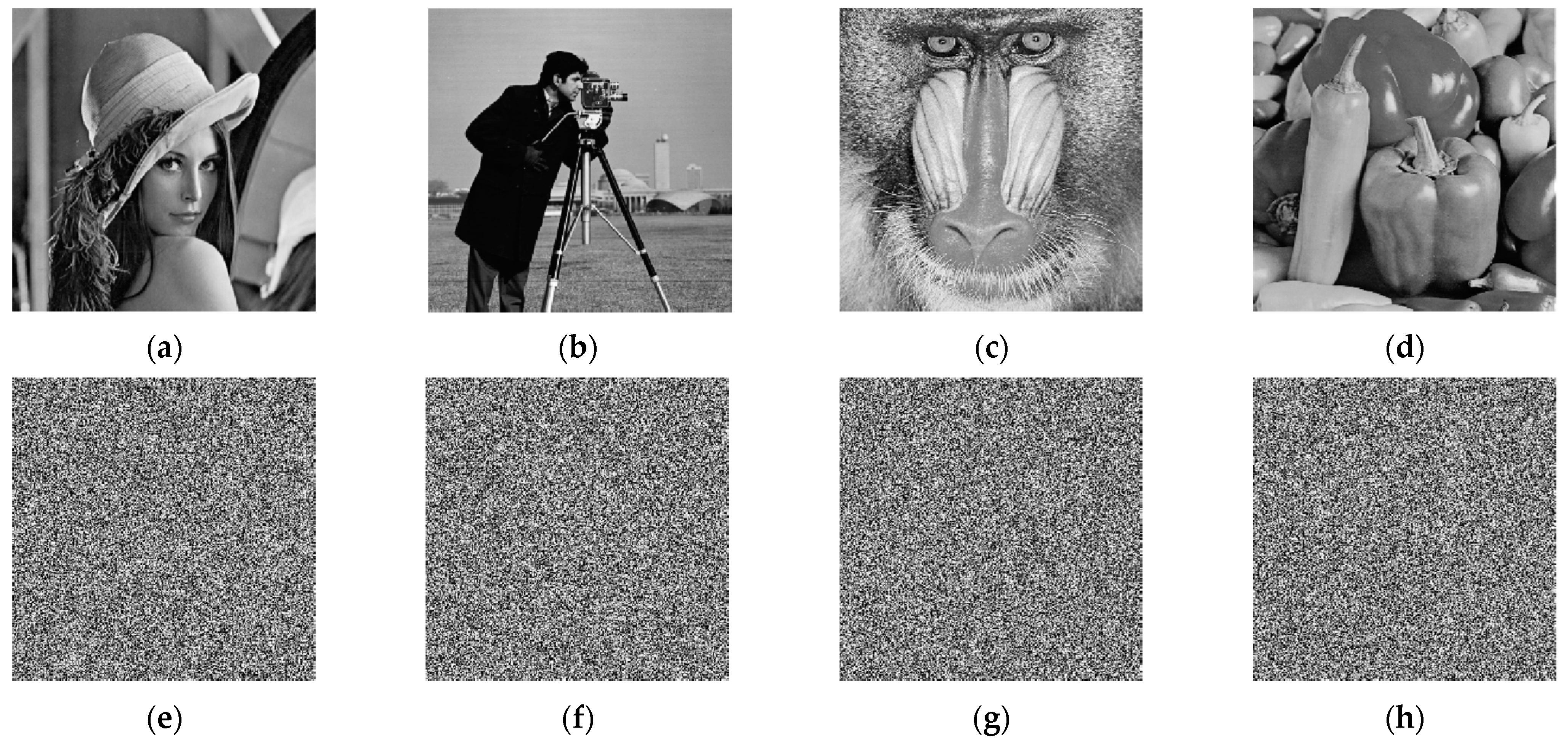
Figure 6 shows the four test images and their encryption ones by the proposed algorithm. One can see that the cipher images that are not related to their respective original images and can no longer be understood.
4.2. Key Space Analysis
Since the algorithm key mainly includes the four initial state values of the four-dimensional chaotic system. The precision of each is 1014, and the total key space is (1014)4 = 1056 > 2186. Therefore, the key space of the algorithm must be larger than 2186. At present, the key space is greater than or equal to 2100 to effectively resist brute force attacks [47]. Therefore, the key space of the proposed algorithm is large enough to effectively resist brute force attacks.
4.3. Information Entropy
The image information entropy reflects the distribution of image gray value. Its expression is as follows [32]:
Among them, represents the i-th gray value of L gray levels, and represents the probability of the appearance of . Ideally, the information entropy of a gray value of the 256-level gray level should be close to 8 [19]. The larger the information entropy value is, the more uniform the pixel gray distribution in the image is the information entropy obtained by this algorithm as shown in Table 10. It can be seen from Table 10 that the information entropy of the encrypted image obtained by this algorithm has been significantly improved. The information entropy of this algorithm is slightly higher than that of the reference, and overall, it is close to 8.
4.4. Histogram
The histogram [50] reflects the uniformity of the gray value distribution of the image. Histograms of the original images and encrypted images are shown in Figure 7 and Figure 8, respectively. It can be seen from Figure 7 that the histogram of each original image is uneven, with high and low, and it is easy to be broken by statistical attacks. However, from Figure 8, one can see that the histograms of images obtained after encryption by this algorithm are evenly distributed, which reduces the risk of being cracked by statistical attacks.
It can be seen from the histogram illustrations of the original image and the encrypted image that the histogram obtained by the encryption algorithm is more uniform, indicating that the proposed cryptosystem can well resist statistical attacks.
4.5. Correlation Coefficient and Point Image
The correlation coefficient [30] is used to measure the correlation degree of adjacent pixels of an image. The definition and calculation method of the correlation coefficient is as follows:
Among them, (xi, yi) represent a pair of gray values of two adjacent pixels in the image, and represents the number of total pairs of randomly selected pixels from the image. The correlation coefficient between adjacent pixels in the original image is very high. After this encryption algorithm, the correlation coefficient is reduced. Ideally, the correlation coefficient should approach 0 [51]. In our experiment, the 256 × 256 gray images Lena, Cameraman, Peppers, and House are tested, 65,280 pairs (horizontal or vertical direction) or 65,025 pairs (diagonal direction) of adjacent pixels are selected, and the correlation coefficient comparison is shown in Table 11.
It can be seen from the correlation coefficient comparison table that the correlation coefficient of the three directions of this algorithm is generally slightly lower than that of the reference. Therefore, the proposed algorithm has a better ability to resist statistical analysis attacks. The distributions of adjacent pixels are shown in Figure 9. Among them (a), (b), and (c) are the correlation point diagrams of the original images in three directions, (d), (e), and (f) are the correlation point diagrams of the encrypted images in three directions.
It can be seen from Figure 9 that the correlation point map of the original images is distributed in a straight line, close to the straight line. After this encryption algorithm, the correlation point map of the encrypted images is evenly distributed, which effectively resists statistical attacks.
4.6. Plaintext Sensitivity Analysis
A fine encryption algorithm should be sensitive to the plaintext [53]. If the plaintext is changed a little, the ciphertext will change greatly. Usually use NPCR, UACI [29] to analyze the difference between two images. It is defined as follows:
Among them, represents the pixel gray value of a ciphertext image corresponding to the original plaintext image at coordinates (i, j), and represents the pixel gray value of a ciphertext image corresponding to the plaintext image that only changes the least significant bit of a pixel value at coordinates (i, j); M and N represent the row number and column number of the image, respectively. D(i, j) is defined as follows: if C(i, j) = C′(i, j), then D(i, j) = 1; otherwise, D(i, j) = 0.
NPCR = 99.6094% and UACI = 33.4635% are the expected values [54]. The larger the value of NPCR and UACI, the greater the difference between ciphertexts, and the better the algorithm is.
We firstly encrypt a plaintext image to obtain its ciphertext image C. Then, we carry out five encryption experiments. In each experiment, select one pixel from the original image and change the least significant bit of it, then encrypt the modified image to obtain the ciphertext image C′. Then, calculate the NPCR and UACI value between C and C′. Comparisons of NPCR and UACI of the encryption image are shown in Table 12 and Table 13, respectively. Table 12 and Table 13, respectively, list the results of NPCR and UACI of ciphertext images obtained by the proposed algorithm and the algorithms of Refs. [24,33,52]. The experimental results show that most of the NPCR and UACI values obtained by this paper are close to 99.6093% and 33.4635%.
From the comparison table of NPCR and UACI, it can be seen that the values of NPCI and UACI fluctuate slightly above and below the ideal value, and most experimental values are higher than the ideal value. Therefore, it can be explained that there is a large distinction between the cipher image generated by changing the pixel value the plain image and the cipher image generated without changing the original image.
4.7. Key Sensitivity Analysis
Key sensitivity [50] means that when the key is slightly changed, it will cause a big change, and the correct restored image cannot be obtained through the decryption algorithm. The original key parameters are {x0 = 1.0, y0 = 1.1, z0 = 3.1, w0 = 3.3.}. This test changes only the parameter x0 from 1.0 to 1.0 + 10−15. Then, obtain the restored image by using the changed key parameters to decrypt the original encrypted one. The comparison between the original encrypted image and the decrypted image obtained by changing the key is shown in Figure 10.
The result of Figure 10 shows such a fact: when the key parameter is changed 10−15, the visually unrecognizable snowflake noise image can be obtained (see Figure 10c). It can be concluded that although the secret key changes very little, the correct decryption image cannot be obtained, indicating that the algorithm has strong key sensitivity.
4.8. Time Performance Analysis
A good algorithm must ensure that the encrypted information can be obtained in a short time, and the encrypted image information can be decrypted within a valid time [2]. In the test, all image encryption algorithms were carried out with MATLAB R2016b and run on a PC with 16.0 GB memory and a CPU of Intel(R) Core (TM) i7-9700 @ 3.00 GHz. The grayscale images Lena, Peppers, and Cameraman were adopted as experimental images. The average execution time of 5 experiments was shown in Table 14 and Table 15 The tables also list the relevant encryption and decryption time data in references [25,30,31,33] as a comparison. From Table 14 and Table 15, one can see that the encryption and decryption time of this algorithm are shorter than that of references [25,30,31,33]. The encryption and decryption time can be controlled at about 1 s, indicating that the algorithm has high time efficiency and strong real-time performance.
5. Conclusions
This paper proposes a novel conservative hyperchaotic system-based image encryption algorithm with dynamic DNA coding. The new conservative hyperchaotic system and the dynamic DNA coding strategy improve the randomness of the encryption algorithm. In the permutation stage, the scrambling result of the image is related closely to the sum S0 of the image’s DNA encoding value, which makes the equivalent secret key related to the content of the encrypted image, so that the algorithm can resist chosen-plaintext attacks. In the diffusion stage, on the one hand, the generation of the intermediate secret keys ni are related closely to the sum of the image DNA encoding value; on the other hand, the ciphertext feedback mechanism of the image DNA encoding is introduced, which not only further improves the algorithm’s ability to resist chosen-plaintext attacks, but also increase the sensitivity of ciphertext to plaintext. Correspondingly, the performance of the algorithm against differential attacks has also been improved. These aspects are some advantages of this algorithm. Simulation experiments and analysis of various security performances show that this algorithm has a good encryption effect and can effectively resist brute force attacks, statistical attacks, chosen-plaintext attacks, and differential attacks. Some disadvantages of this algorithm are that the time cost of generating hyperchaotic system sequences and DNA encoding and decoding is large. A direction worthy of future research is that the speed of DNA coding algorithms needs to be further improved. The proposed cryptosystem can be further improved by expanding the methods of scrambling and diffusion.
Author Contributions
Conceptualization, C.Z. and Q.L.; methodology, L.Y.; software, C.Z.; validation, C.Z., Q.L. and L.Y.; formal analysis, C.Z.; investigation, Q.L.; resources, Q.L.; data curation, Q.L.; writing—original draft preparation, Q.L.; writing—review and editing, C.Z. and L.Y.; visualization, C.Z.; supervision, C.Z.; project administration, Q.L. and L.Y.; funding acquisition, Q.L. All authors have read and agreed to the published version of the manuscript.
Funding
This work was supported in part by the Open Research Fund of Key Laboratory of Network Crime Investigation of Hunan Provincial Colleges under Grant 2020WLFZZC002, in part by the Science and Technology Innovation Leading Plan for High-tech Industry of Hunan Province (Science and Technology Tackling) Project under Grant 2020GK2029, in part by educational science planning project of Hunan Education Department under Grant XJK20CGD053.
Institutional Review Board Statement
Not applicable.
Informed Consent Statement
Not applicable.
Data Availability Statement
Data sharing not applicable.
Acknowledgments
The authors are thankful to the reviewers for their comments and suggestions to improve the quality of the manuscript.
Conflicts of Interest
The authors declare no conflict of interest.
References
- Zhang, J.Y.; Zhong, S.Q.; Wang, T.; Chao, H.C.; Wang, J. Blockchain-based Systems and Applications: A Survey. J. Internet Technol. 2020, 21, 1–14. [Google Scholar] [CrossRef]
- Zhang, Q.; Han, J.; Ye, Y. Multi-image encryption algorithm based on image hash, bit-plane decomposition and dynamic DNA coding. IET Image Process. 2020, 15, 885–896. [Google Scholar] [CrossRef]
- Yuan, H.-M.; Liu, Y.; Gong, L.-H.; Wang, J. A new image cryptosystem based on 2D hyper-chaotic system. Multimed. Tools Appl. 2017, 76, 8087–8108. [Google Scholar] [CrossRef]
- Lu, W.; Zhang, X.; Lu, H.; Li, F. Deep hierarchical encoding model for sentence semantic matching. J. Vis. Commun. Image Represent. 2020, 71, 102794. [Google Scholar] [CrossRef]
- Lu, Q.; Zhu, C.; Deng, X. An Efficient Image Encryption Scheme Based on the LSS Chaotic Map and Single S-Box. IEEE Access 2020, 8, 25664–25678. [Google Scholar] [CrossRef]
- Zhu, S.; Zhu, C. Secure Image Encryption Algorithm Based on Hyperchaos and Dynamic DNA Coding. Entropy 2020, 22, 772. [Google Scholar] [CrossRef] [PubMed]
- Masood, F.; Driss, M.; Boulila, W.; Ahmad, J.; Rehman, S.U.; Jan, S.U.; Qayyum, A.; Buchanan, W.J. A Lightweight Chaos-Based Medical Image Encryption Scheme Using Random Shuffling and XOR Operations. Wirel. Pers. Commun. 2021, 1–28. [Google Scholar] [CrossRef]
- Chen, Y.; Liu, L.; Tao, J.; Xia, R.; Zhang, Q.; Yang, K.; Xiong, J.; Chen, X. The improved image inpainting algorithm via encoder and similarity constraint. Vis. Comput. 2021, 37, 1691–1705. [Google Scholar] [CrossRef]
- Diaconu, A.-V. Circular inter–intra pixels bit-level permutation and chaos-based image encryption. Inf. Sci. 2016, 355, 314–327. [Google Scholar] [CrossRef]
- Zhu, S.; Wang, G.; Zhu, C. A Secure and Fast Image Encryption Scheme based on Double Chaotic S-Boxes. Entropy 2019, 21, 790. [Google Scholar] [CrossRef] [Green Version]
- Hua, Z.; Jin, F.; Xu, B.; Huang, H. 2D Logistic-Sine-coupling map for image encryption. Signal Process. 2018, 149, 148–161. [Google Scholar] [CrossRef]
- Attaullah; Javeed, A.; Shah, T. Cryptosystem techniques based on the improved Chebyshev map: An application in image encryption. Multimed. Tools Appl. 2019, 78, 31467–31484. [Google Scholar] [CrossRef]
- Zhou, M.; Wang, C. A novel image encryption scheme based on conservative hyperchaotic system and closed-loop diffusion between blocks. Signal Process. 2020, 171, 107484. [Google Scholar] [CrossRef]
- Gu, S.; Du, B.; Wan, Y. A New Four-Dimensional Non-Hamiltonian Conservative Hyperchaotic System. Int. J. Bifurc. Chaos 2020, 30, 2050242. [Google Scholar] [CrossRef]
- Lipton, R.J. DNA Solution of Hard Computational Problems. Science 1995, 268, 542–545. [Google Scholar] [CrossRef] [PubMed] [Green Version]
- Braich, R.S.; Chelyapov, N.; Johnson, C.; Rothemund, P.W.K.; Adleman, L. Solution of a 20-Variable 3-SAT Problem on a DNA Computer. Science 2002, 296, 499–502. [Google Scholar] [CrossRef] [Green Version]
- Clelland, C.T.; Risca, V.; Bancroft, C. Hiding messages in DNA microdots. Nat. Cell Biol. 1999, 399, 533–534. [Google Scholar] [CrossRef] [PubMed]
- Leier, A.; Richter, C.; Banzhaf, W.; Rauhe, H. Cryptography with DNA binary strands. Biosystems 2000, 57, 13–22. [Google Scholar] [CrossRef]
- Wang, X.; Hou, Y.; Wang, S.; Li, R. A New Image Encryption Algorithm Based on CML and DNA Sequence. IEEE Access 2018, 6, 62272–62285. [Google Scholar] [CrossRef]
- Wang, X.; Wang, Y.; Zhu, X.; Unar, S. Image encryption scheme based on Chaos and DNA plane operations. Multimed. Tools Appl. 2019, 78, 26111–26128. [Google Scholar] [CrossRef]
- Wu, J.; Liao, X.; Yang, B. Color image encryption based on chaotic systems and elliptic curve ElGamal scheme. Signal Process. 2017, 141, 109–124. [Google Scholar] [CrossRef]
- Azimi, Z.; Ahadpour, S. Color image encryption based on DNA encoding and pair coupled chaotic maps. Multimed. Tools Appl. 2020, 79, 1727–1744. [Google Scholar] [CrossRef]
- Dagadu, J.C.; Li, J.P.; Addo, P.C. An image cryptosystem based on pseudorandomly enhanced chaotic DNA and random permutation. Multimed. Tools Appl. 2019, 78, 24979–25000. [Google Scholar] [CrossRef]
- Chai, X.; Fu, X.; Gan, Z.; Lu, Y.; Chen, Y. A color image cryptosystem based on dynamic DNA encryption and chaos. Signal Process. 2019, 155, 44–62. [Google Scholar] [CrossRef]
- Chai, X.; Gan, Z.; Yuan, K.; Chen, Y.; Liu, X. A novel image encryption scheme based on DNA sequence operations and chaotic systems. Neural Comput. Appl. 2019, 31, 219–237. [Google Scholar] [CrossRef]
- Telem, A.N.K.; Fotsin, H.B.; Kengne, J. Image encryption algorithm based on dynamic DNA coding operations and 3D chaotic systems. Multimed. Tools Appl. 2021, 80, 19011–19041. [Google Scholar] [CrossRef]
- Hui, Y.; Liu, H.; Fang, P. A DNA image encryption based on a new hyperchaotic system. Multimed. Tools Appl. 2021, 2021, 1–25. [Google Scholar] [CrossRef]
- Zhang, Q.; Guo, L.; Wei, X. A novel image fusion encryption algorithm based on DNA sequence operation and hyper-chaotic system. Optik 2013, 124, 3596–3600. [Google Scholar] [CrossRef]
- Song, C.; Qiao, Y. A Novel Image Encryption Algorithm Based on DNA Encoding and Spatiotemporal Chaos. Entropy 2015, 17, 6954–6968. [Google Scholar] [CrossRef]
- Wang, X.; Liu, C. A novel and effective image encryption algorithm based on chaos and DNA encoding. Multimed. Tools Appl. 2017, 76, 6229–6245. [Google Scholar] [CrossRef]
- Hu, T.; Liu, Y.; Gong, L.-H.; Ouyang, C.-J. An image encryption scheme combining chaos with cycle operation for DNA sequences. Nonlinear Dyn. 2016, 87, 51–66. [Google Scholar] [CrossRef]
- Zhang, Y. The image encryption algorithm based on chaos and DNA computing. Multimed. Tools Appl. 2018, 77, 21589–21615. [Google Scholar] [CrossRef]
- Yan, X.; Wang, X.; Xian, Y. Chaotic image encryption algorithm based on arithmetic sequence scrambling model and DNA encoding operation. Multimed. Tools Appl. 2021, 80, 10949–10983. [Google Scholar] [CrossRef]
- Wen, H.; Yu, S.; Lü, J. Breaking an Image Encryption Algorithm Based on DNA Encoding and Spatiotemporal Chaos. Entropy 2019, 21, 246. [Google Scholar] [CrossRef] [PubMed] [Green Version]
- Xie, T.; Liu, Y.; Tang, J. Breaking a novel image fusion encryption algorithm based on DNA sequence operation and hyper-chaotic system. Optik 2014, 125, 7166–7169. [Google Scholar] [CrossRef]
- Zhang, Y. Cryptanalysis of a novel image fusion encryption algorithm based on DNA sequence operation and hyper-chaotic system. Optik 2015, 126, 223–229. [Google Scholar] [CrossRef]
- Zhu, S.; Zhu, C. An Efficient Chosen-Plaintext Attack on an Image Fusion Encryption Algorithm Based on DNA Operation and Hyperchaos. Entropy 2021, 23, 804. [Google Scholar] [CrossRef]
- Masood, F.; Boulila, W.; Ahmad, J.; Arshad, A.; Sankar, S.; Rubaiee, S.; Buchanan, W. A Novel Privacy Approach of Digital Aerial Images Based on Mersenne Twister Method with DNA Genetic Encoding and Chaos. Remote Sens. 2020, 12, 1893. [Google Scholar] [CrossRef]
- Masood, F.; Ahmad, J.; Shah, S.A.; Jamal, S.S.; Hussain, I. A Novel Hybrid Secure Image Encryption Based on Julia Set of Fractals and 3D Lorenz Chaotic Map. Entropy 2020, 22, 274. [Google Scholar] [CrossRef] [Green Version]
- Lin, C.-Y.; Wu, J.-L. Cryptanalysis and Improvement of a Chaotic Map-Based Image Encryption System Using Both Plaintext Related Permutation and Diffusion. Entropy 2020, 22, 589. [Google Scholar] [CrossRef]
- Li, M.; Zhou, K.; Ren, H.; Fan, H. Cryptanalysis of Permutation–Diffusion-Based Lightweight Chaotic Image Encryption Scheme Using CPA. Appl. Sci. 2019, 9, 494. [Google Scholar] [CrossRef] [Green Version]
- Zhu, C.; Wang, G.; Sun, K. Improved Cryptanalysis and Enhancements of an Image Encryption Scheme Using Combined 1D Chaotic Maps. Entropy 2018, 20, 843. [Google Scholar] [CrossRef] [PubMed] [Green Version]
- Dong, E.; Yuan, M.; Du, S.; Chen, Z. A new class of Hamiltonian conservative chaotic systems with multistability and design of pseudo-random number generator. Appl. Math. Model. 2019, 73, 40–71. [Google Scholar] [CrossRef]
- Akhshani, A.; Akhavan, A.; Mobaraki, A.; Lim, S.C.; Hassan, Z. Pseudo random number generator based on quantum chaotic map. Commun. Nonlinear Sci. Numer. Simul. 2014, 19, 101–111. [Google Scholar] [CrossRef]
- Benítez, R.; Bolós, V.J.; Ramírez, M.E. A wavelet-based tool for studying non-periodicity. Comput. Math. Appl. 2010, 60, 634–641. [Google Scholar] [CrossRef] [Green Version]
- Bolós, V.J.; Benítez, R. wavScalogram: Wavelet Scalogram Tools for Time Series Analysis; R Package Version 1.0.0. 2019. Available online: https://CRAN.R-project.org/package=wavScalogram (accessed on 28 September 2021).
- Guan, M.M.; Yang, X.L.; Hu, W.S. Chaotic image encryption algorithm using frequency-domain DNA encoding. Iet Image Process. 2019, 13, 1535–1539. [Google Scholar] [CrossRef]
- Cao, C.; Sun, K.; Liu, W. A novel bit-level image encryption algorithm based on 2D-LICM hyperchaotic map. Signal Process. 2018, 143, 122–133. [Google Scholar] [CrossRef]
- Zheng, J.; Luo, Z.; Zeng, Q. An efficient image encryption algorithm based on multi chaotic system and random DAN coding. Multimed. Tools Appl. 2020, 79, 29901–29921. [Google Scholar] [CrossRef]
- Gan, Z.; Chai, X.; Han, D.; Chen, Y. A chaotic image encryption algorithm based on 3-D bit-plane permutation. Neural Comput. Appl. 2019, 31, 7111–7130. [Google Scholar] [CrossRef]
- Zhang, S.; Gao, T. An image encryption scheme based on DNA coding and permutation of hyper-image. Multimed. Tools Appl. 2015, 75, 17157–17170. [Google Scholar] [CrossRef]
- Alawida, M.; Samsudin, A.; Sen Teh, J.; Alkhawaldeh, R.S. A new hybrid digital chaotic system with applications in image encryption. Signal Process. 2019, 160, 45–58. [Google Scholar] [CrossRef]
- Tong, X.J.; Liu, Y.; Zhang, M.; Xu, H.; Wang, Z. An Image Encryption Scheme Based on Hyperchaotic Rabinovich and Exponential Chaos Maps. Entropy 2015, 17, 181–196. [Google Scholar] [CrossRef]
- Xu, Q.; Sun, K.; Cao, C.; Zhu, C. A fast image encryption algorithm based on compressive sensing and hyperchaotic map. Opt. Lasers Eng. 2019, 121, 203–214. [Google Scholar] [CrossRef]
Figure 1.
Phase portraits of system (1) with a = 12, b = c = 8 and (x0, y0, z0, w0) = (1, 1.1, 3.2, 3.3); (a) x-y plane; (b) y-z plane; (c) y-w plane; (d) x-y-z space; (e) y-z-w space; (f) x-z-w space.
Figure 1.
Phase portraits of system (1) with a = 12, b = c = 8 and (x0, y0, z0, w0) = (1, 1.1, 3.2, 3.3); (a) x-y plane; (b) y-z plane; (c) y-w plane; (d) x-y-z space; (e) y-z-w space; (f) x-z-w space.


Figure 2.
Lyapunov exponent spectrum and bifurcation diagrams of system (1). (a) Lyapunov exponents versus a with b = c = 8 and (x0, y0, z0, w0) = (2, 2, 2, 2). (b) Bifurcation of x versus a with b = c = 8 and (x0, y0, z0, w0) = (2, 2, 2, 2). (c) Lyapunov exponents versus b with a = 12, c = 8 and (x0, y0, z0, w0) = (2, 2, 2, 2). (d) Bifurcation of x versus b with a = 12, c = 8 and (x0, y0, z0, w0) = (2, 2, 2, 2). (e) Lyapunov exponents versus c with a = 12, b = 8 and (x0, y0, z0, w0) = (2, 2, 2, 2). (f) Bifurcation of x versus c with a = 12, b = 8 and (x0, y0, z0, w0) = (2, 2, 2, 2).

Figure 3.
Scale index of system (1). (a) Scale index with b = c = 8, a = 11.3 and a = 13. (b) Scale index with a = 12, c = 8, b = 9 and b = 10. (c) Scale index with a = 12, b = 8, c = 8 and c = 9. (d) Scale index of the CCS with a = 12, b = c = 8 and the logistic map with μ = 4.
Figure 3.
Scale index of system (1). (a) Scale index with b = c = 8, a = 11.3 and a = 13. (b) Scale index with a = 12, c = 8, b = 9 and b = 10. (c) Scale index with a = 12, b = 8, c = 8 and c = 9. (d) Scale index of the CCS with a = 12, b = c = 8 and the logistic map with μ = 4.


Figure 4.
The BlockAlphabit test results for the CCS (1).

Figure 5.
The block diagram of the proposed crypto-system.

Figure 6.
Typical plaintext images and their ciphertext images. (a) The plaintext image lena. (b) Plaintext image cameraman. (c) Plaintext image baboon. (d) Plaintext image peppers. (e) Ciphertext image of (a). (f) Ciphertext image of (b). (g) Ciphertext image of (c). (h) Ciphertext image of (d).
Figure 6.
Typical plaintext images and their ciphertext images. (a) The plaintext image lena. (b) Plaintext image cameraman. (c) Plaintext image baboon. (d) Plaintext image peppers. (e) Ciphertext image of (a). (f) Ciphertext image of (b). (g) Ciphertext image of (c). (h) Ciphertext image of (d).

Figure 7.
Histogram of the original image. (a) Histogram of the lena. (b) Histogram of the cameraman. (c) Histogram of the baboon. (d) Histogram of the peppers.
Figure 7.
Histogram of the original image. (a) Histogram of the lena. (b) Histogram of the cameraman. (c) Histogram of the baboon. (d) Histogram of the peppers.

Figure 8.
Histogram of the encrypted image. (a) Histogram of the encrypted lena. (b) Histogram of the encrypted cameraman. (c) Histogram of the encrypted baboon. (d) Histogram of the encrypted peppers.
Figure 8.
Histogram of the encrypted image. (a) Histogram of the encrypted lena. (b) Histogram of the encrypted cameraman. (c) Histogram of the encrypted baboon. (d) Histogram of the encrypted peppers.

Figure 9.
Horizontal, vertical, diagonal correlation point diagrams of original image and encryption image. (a) Original Lena horizontal; (b) original Lena vertical; (c) original Lena diagonal; (d) encrypted Lena horizontal; (e) encrypted Lena vertical; (f) encrypted Lena diagonal.
Figure 9.
Horizontal, vertical, diagonal correlation point diagrams of original image and encryption image. (a) Original Lena horizontal; (b) original Lena vertical; (c) original Lena diagonal; (d) encrypted Lena horizontal; (e) encrypted Lena vertical; (f) encrypted Lena diagonal.

Figure 10.
Encryption and decryption image after changing the key. (a) The encrypted image; (b) decrypted image with right keys; (c) decrypted image with wrong key x0 has 10−15 error.
Figure 10.
Encryption and decryption image after changing the key. (a) The encrypted image; (b) decrypted image with right keys; (c) decrypted image with wrong key x0 has 10−15 error.


Table 1.
Multiscale sample entropy of sequence X (m = 2, s = 0.2).
| MsEn (t = 1) | MsEn (t = 2) | MsEn (t = 3) | MsEn (t = 4) | MsEn (t = 5) |
|---|---|---|---|---|
| 0.1717 | 0.3529 | 0.4487 | 0.4968 | 0.5287 |
Table 2.
Approximate entropy of sequence X (r = 0.2).
| ApEn (m = 1) | ApEn (m = 2) | ApEn (m = 3) | ApEn (m = 4) | ApEn (m = 5) |
|---|---|---|---|---|
| 0.1456 | 0.1789 | 0.2042 | 0.1914 | 0.1646 |
Table 3.
Summary results of Rabbit test.
| Test Name | Number of Bits | Number of Statistics | Summary Results |
|---|---|---|---|
| Rabbit | 1,048,576 | 38 | All tests were passed |
| Rabbit | 6,000,000 | 39 | All tests were passed |
Table 4.
The results of Alphabit test.
| Test Name | Parameters | Max of p-Value | Min of p-Value | Summary Results of Alphabit |
|---|---|---|---|---|
| smultin_MultinomialBitsOver | Standard | 0.86 | 0.42 | All tests were passed |
| sstring_HammingIndep | Standard | 0.9927 | 0.51 | |
| swalk_RandomWalk1(Test on the values of the Statistic H) | Standard | 0.64 | 0.03 | |
| swalk_RandomWalk1(Test on the values of the Statistic M) | Standard | 0.77 | 0.33 | |
| swalk_RandomWalk1(Test on the values of the Statistic J) | Standard | 0.32 | 0.07 | |
| swalk_RandomWalk1(Test on the values of the Statistic R) | Standard | 0.38 | 0.06 | |
| swalk_RandomWalk1(Test on the values of the Statistic C) | Standard | 0.92 | 0.67 |
Table 5.
NIST statistical test results for 20 sequences of size 1 million bits.
| NIST Statistical Test | p-Value | Pass Rate | Results |
|---|---|---|---|
| Frequency (monobit) | 0.275709 | 100% | pass |
| Block frequency (m = 128) | 0.534146 | 100% | pass |
| Cumulative sums (forward) | 0.213309 | 100% | pass |
| Cumulative sums (reverse) | 0.350485 | 100% | pass |
| Runs | 0.739918 | 95.0% | pass |
| Longest run of ones | 0.911413 | 100% | pass |
| Rank | 0.739918 | 95.0% | pass |
| FFT | 0.834308 | 100% | pass |
| Non-overlapping templates (m = 9) | >0.01 | ≥90% | pass |
| Overlapping templates (m = 9) | 0.350485 | 100% | pass |
| Universal | 0.911413 | 95.0% | pass |
| Approximate entropy (m = 10) | 0.275709 | 100% | pass |
| Random-excursions | >0.01 | 100% | pass |
| Random-excursions variant | >0.01 | ≥87.5% | pass |
| Serial test 1 (m = 16) | 0.122325 | 100% | pass |
| Serial test 2 (m = 16) | 0.534146 | 100% | pass |
| Linear complexity (M = 500) | 0.437274 | 100% | pass |
Table 6.
DNA coding rules.
| Bases | Rule 1 | Rule 2 | Rule 3 | Rule 4 | Rule 5 | Rule 6 | Rule 7 | Rule 8 |
|---|---|---|---|---|---|---|---|---|
| 00 | A | A | G | C | G | C | T | T |
| 01 | G | C | A | A | T | T | G | C |
| 10 | C | G | T | T | A | A | C | G |
| 11 | T | T | C | G | C | G | A | A |
Table 7.
A newly defined operation rule for DNA addition.
| ADD | A | C | G | T |
|---|---|---|---|---|
| A | A | C | G | T |
| C | C | G | T | A |
| G | G | T | A | C |
| T | T | A | C | G |
Table 8.
A newly defined operation rule for DNA subtraction.
| SUB | A | C | G | T |
|---|---|---|---|---|
| A | A | T | G | C |
| C | C | A | T | G |
| G | G | C | A | T |
| T | T | G | C | A |
Table 9.
A newly defined operation rule for DNA XOR.
| XOR | A | C | G | T |
|---|---|---|---|---|
| A | A | C | G | T |
| C | C | A | T | G |
| G | G | T | A | C |
| T | T | G | C | A |
Table 10.
Information entropy values of the cipher images obtained by different algorithms.
| Images | Image Size | Plain Images | Encrypted Images | ||||
|---|---|---|---|---|---|---|---|
| Ours | Ref. [48] | Ref. [49] | Ref. [10] | Ref. [23] | |||
| Lena | 256 × 256 | 7.5683 | 7.9978 | 7.9968 | 7.9974 | 7.9976 | 7.9968 |
| Cameraman | 256 × 256 | 7.0097 | 7.9972 | / | / | 7.9970 | / |
| Baboon | 256 × 256 | 7.3385 | 7.9975 | 7.9975 | 7.9971 | 7.9968 | 7.9972 |
| Peppers | 256 × 256 | 7.5251 | 7.9973 | 7.9970 | 7.9970 | 7.9975 | 7.9974 |
| All black | 256 × 256 | 0 | 7.9973 | / | / | 7.9972 | / |
| All white | 256 × 256 | 0 | 7.9974 | / | / | 7.9968 | / |
| Lena | 512 × 512 | 7.4456 | 7.9994 | 7.9992 | 7.9995 | 7.9993 | 7.9994 |
| Baboon | 512 × 512 | 7.3579 | 7.9993 | 7.9994 | 7.9992 | 7.9993 | 7.9990 |
| Peppers | 512 × 512 | 7.5715 | 7.9993 | 7.9992 | 7.9993 | 7.9993 | 7.9993 |
Table 11.
Correlation coefficients of the Lena cipher images encrypted by different algorithms.
| Imagess | Directions | This Work | Ref. [33] | Ref. [52] | Ref. [24] |
|---|---|---|---|---|---|
| Lena | Horizontal | −0.0022 | −0.0016 | −0.0063 | −0.0086 |
| Vertical | 0.0037 | 0.0043 | 0.0109 | −0.1020 | |
| Diagonal | 0.0039 | −0.0026 | −0.0154 | 0.0125 | |
| Cameraman | Horizontal | −0.0037 | 0.0005 | −0.0009 | −0.0211 |
| Vertical | −0.0022 | 0.0020 | −0.0223 | −0.0103 | |
| Diagonal | −0.0024 | 0.0002 | 0.0025 | 0.0054 | |
| Peppers | Horizontal | −0.0010 | 0.0070 | 0.0038 | −0.0089 |
| Vertical | −0.0002 | −0.0008 | −0.0082 | −0.0113 | |
| Diagonal | 0.0021 | −0.0034 | 0.0078 | 0.0045 | |
| House | Horizontal | 5.6925 × 10⁻⁵ | −0.0051 | 0.0109 | −0.0126 |
| Vertical | −0.0021 | 0.0022 | −0.0173 | −0.0097 | |
| Diagonal | 0.0017 | 0.0055 | −0.0002 | −0.0123 |
Table 12.
Comparison of NPCR values in ciphertext images.
| Images | Image Size | This Work | Ref. [33] | Ref. [52] | Ref. [24] |
|---|---|---|---|---|---|
| Lena | 256 × 256 | 0.99626 | 0.99610 | 0.99623 | 0.99615 |
| Cameraman | 256 × 256 | 0.99603 | 0.99638 | 0.99622 | 0.99629 |
| Peppers | 256 × 256 | 0.99626 | 0.99626 | 0.99573 | 0.99609 |
| House | 256 × 256 | 0.99609 | 0.99625 | 0.99608 | 0.99626 |
| 5.1.12 | 256 × 256 | 0.99608 | 0.99648 | 0.99573 | 0.99622 |
| Elaine | 512 × 512 | 0.99611 | 0.99600 | 0.99553 | 0.99610 |
| 5.2.08 | 512 × 512 | 0.99609 | 0.99625 | 0.99547 | 0.99629 |
| 7.1.03 | 512 × 512 | 0.99608 | 0.99619 | 0.99608 | 0.99613 |
Table 13.
Comparison of UACI values in ciphertext images.
| Images | Image Size | This Work | Ref. [33] | Ref. [52] | Ref. [24] |
|---|---|---|---|---|---|
| Lena | 256 × 256 | 0.33486 | 33.5463 | 33.8144 | 33.5561 |
| Cameraman | 256 × 256 | 0.335913 | 33.4239 | 33.7326 | 33.7050 |
| Peppers | 256 × 256 | 0.33638 | 0.33477 | 0.33472 | 0.33628 |
| House | 256 × 256 | 0.33493 | 33.5114 | 33.7656 | 33.7022 |
| 5.1.12 | 256 × 256 | 0.33374 | 33.4866 | 33.9272 | 33.4836 |
| Elaine | 512 × 512 | 0.33445 | 33.4301 | 33.7063 | 33.6163 |
| 5.2.08 | 512 × 512 | 0.33539 | 33.4939 | 33.8911 | 33.6446 |
| 7.1.03 | 512 × 512 | 0.33509 | 33.5499 | 33.7415 | 33.7155 |
Publisher’s Note: MDPI stays neutral with regard to jurisdictional claims in published maps and institutional affiliations. |
© 2021 by the authors. Licensee MDPI, Basel, Switzerland. This article is an open access article distributed under the terms and conditions of the Creative Commons Attribution (CC BY) license (https://creativecommons.org/licenses/by/4.0/).
Share and Cite
MDPI and ACS Style
Lu, Q.; Yu, L.; Zhu, C. A New Conservative Hyperchaotic System-Based Image Symmetric Encryption Scheme with DNA Coding. Symmetry 2021, 13, 2317. https://0-doi-org.brum.beds.ac.uk/10.3390/sym13122317
AMA Style
Lu Q, Yu L, Zhu C. A New Conservative Hyperchaotic System-Based Image Symmetric Encryption Scheme with DNA Coding. Symmetry. 2021; 13(12):2317. https://0-doi-org.brum.beds.ac.uk/10.3390/sym13122317
Chicago/Turabian StyleLu, Qing, Linlan Yu, and Congxu Zhu. 2021. "A New Conservative Hyperchaotic System-Based Image Symmetric Encryption Scheme with DNA Coding" Symmetry 13, no. 12: 2317. https://0-doi-org.brum.beds.ac.uk/10.3390/sym13122317
Note that from the first issue of 2016, this journal uses article numbers instead of page numbers. See further details here.