Article

Optimization of the Motion Algorithm and Reduction of the External Dynamic Load of the Machinery Actuator in Translational and Rotational Modes

1
Faculty of Automotive and Mechanical Engineering, National Transport University, M. Omelianovicha-Pavlenka 1, 01010 Kiev, Ukraine
2
Faculty of Mechanical Engineering, University of Zilina, Univerzitna 1, 010 26 Zilina, Slovakia
*
Author to whom correspondence should be addressed.
Submission received: 23 November 2021 / Revised: 20 December 2021 / Accepted: 22 December 2021 / Published: 1 January 2022

Abstract

:
This article deals with the theoretical preconditions for creating a high-performance, universal earthmoving vehicle with continuous motion that can create long grooves of different depths and widths in the soil using a single actuator. For this purpose, a new symmetrical rotor actuator was developed, which operates in translational and rotational modes due to the two-level actuator with a double-swivel mounting on the base chassis, instead of the traditional single-swivel mounting. Its use eliminates the possibility of leveling the thickness of the shavings when digging the soil. The rotor-actuator-movement algorithm at the front part was developed from a combination of vehicle movement and cyclic-lateral-actuator movement. In real practice, this means digging up the soil with even shavings. The implementation of the developed algorithm in the physical model of the symmetrical actuator confirmed the possibility of balancing the thickness of the shavings, which are cut by the rotor buckets with up to 10% accuracy. The difference between the results in determining the thickness of the shavings analytically and experimentally is 12% with a confidence interval of 0.95.

1. Problem Formulation

Construction and road engineering are subject to the general laws of their development [1,2,3]. The emergence and increasing production of innovative vehicles that are qualitatively different from the previous designs is not a consequence of the jump-like optimization of structures with the same technological purposes [4,5,6]. With increasing improvements, the design and technical characteristics of the vehicles change [7,8,9]. At the same time, there is a revolutionary shift in construction, mainly due to non-traditional tasks that need to be completed.
One of these tasks that should be considered is the need to expand the technological capabilities of continuous earthmoving machinery, as their performance under other equivalent conditions is 4–5 times higher than that of single-bucket excavators [10,11,12]. The problem is solved by increasing the versatility of the work equipment and their drives for the specified class of machine [13,14,15].
Transport constructions are associated with quite a significant amount of earthwork [16,17]. The requirements for their implementation indicate the urgent need to create modern, high-performance earthmoving vehicles, especially continuous excavators. There are typical sizes of excavators that only allow for the digging of long grooves of a given profile in the soil. Digging grooves of another profile is possible by re-equipping the vehicle with variable operating equipment [13,16,18].
In accordance with the principles of creating universal earthmoving machines [13,16], some of them, namely the special earthmoving machines PZM-1 and PZM-2, have found their industrial implementation [19,20].
The operation of such machinery is characterized by significant fluctuations in external loads, affecting the actuator during digging due to the uneven thickness of the shavings cut by the actuator. The creation of a universal earthmoving machine will make it possible to increase its utilization coefficient in various constructions by 5–7 times and also significantly increase the pace of earthwork in construction.
In this case, due to the cyclic reciprocating movement of the working body in the soil-digging mode, the thickness of the shavings changes from zero to the maximum and the magnitude of the external load increases by 4–6 times during the cycle [13,19]. As a result, current machines have insufficient reliability and durability when working on surfaces that have low coefficients of adhesion; it is problematic to ensure their stability in the process of digging the soil.
In view of the above, it is relevant and up to date to create a high-performance, universal continuous earthmoving machine (UCEM) that is capable of digging long symmetrical grooves of various linear dimensions and technological purposes using a single actuator under various ground conditions. This will greatly expand the scope of the vehicle’s use and improve production efficiency due to the increased mass production of similar products, the reduced range of the industrial production of continuous earthmoving machinery, and the reduced cost of their manufacture. Their use will increase the pace of earthwork and improve the quality and accuracy of operations [13,16,18].

2. The Analysis of Research Results and Publications

The well-known technical solutions for creating a UCEM are characterized by their imperfection, and the published research results in this area are fragmentary, unsystematic and do not answer the fundamental questions of creating and ensuring a highly productive UCEM. Therefore, the problem of creating a high-performance UCEM based on a systems approach is acute. It is possible by determining the optimal layout of the machinery, by optimizing the kinematics of the movement of the machinery-operating equipment in the ground, and by developing tools to ensure the UCEM course stability in its maximum performance mode as determining conditions for providing the machinery efficiency when digging the soil.
The search for ways to increase the range of earthwork has given impetus to the development of fundamentally new construction decisions regarding the earthmoving vehicle, its actuator mountings and the actuators themselves. This warrants the creation of a UCEM that, without changing its design, is capable of forming long grooves of various linear dimensions using a single actuator in various ground conditions.
Well-known scientists Dombrovsky, M. H. [21], Fedorov, D. I. [22], Harbuzov, Z. Ye. [23], Balovnev, V. I. [24], Bykov, O. V. [14], Sokolski, M. [13] et al. have performed studies in which they dealt with the creation of effective actuator designs and continuous-earthmoving-vehicle drives. Their research has become fundamental and remains relevant today.
First of all, this applies to the choice of structures of the tillage working bodies for universal earthmoving machines and to the calculation of the external loads acting on the working body in the digging mode.
In recent years, well-known scientists, namely Kravets, S. V. [25], Kyrychenko, I. H. [26], Musiiko, V. D., Koval, A. B. [4], Khmara, L. A. [27] et al. have been dealing with the problems of improving the design of undercarriage and operating equipment of the UCEM. The conclusion from the analysis of the research results is as follows.
New earthmoving vehicles should be continuous vehicles with a chain-and-bar, rotor, or milling-and-rotor actuator. This is quite logical, because the use of continuous earthmoving vehicles reduces the amount of earthwork to be performed on construction sites by 35–45% compared with cyclic machinery [28,29]. It reduces their costs by almost half and increases the pace of operations by several times. When choosing the type of actuator for earthmoving vehicles, it should be noted that in rotor-trench vehicles the distribution of the engine power between digging, soil selection from the face and movement of the vehicle is generally more favorable than in chain vehicles [30,31]. According to M.H. Dombrowsky [17], a rotor-trench vehicle spends from 67% to 81% of its engine power on digging compared to 31–66% for a chain vehicle. Therefore, when digging irrigation canals or trenches with other technological purposes to a depth of 2 m, it is appropriate to use rotor actuators. The more significant expenditure of soil excavation by chain actuators is explained by the substantial friction forces required to move traction chains on guides, the need to overcome friction forces in numerous chain swivels, additional energy consumption for soil grinding, as well as a significant transfer of the developed soil (up to 20–30%) to the trench due to its inefficient unloading. This effect is manifested to the maximum extent when digging moist, loamy and clayey soils [4,14,25].
Thus, a rotary working body with centrifugal unloading should be used as a tillage working body for a universal earthmoving machine.
According to the layout diagram shown in Figure 1, all known designs of universal earthmoving machines have been built, including the PZM-1 and PZM-2 machines.
The value of the energy intensity of soil excavation, as the main integral characteristics of the actuator efficiency, or the vehicle as a whole, depends on the properties of the excavated soils, the ability to change the soil supply and cutting ratio and, of course, the design of the actuators [30,31,32].
The above-mentioned design enables us to objectively choose the actuator type at the design stage that will be used in a special earthmoving vehicle with different technological purposes.
A kinematic analysis shows that any actuator of the considered UCEM performs simple oscillating motions in the horizontal plane relative to the vertical axis. In this plane, it can create a face with shavings of uneven thickness in the form of a sickle, wedge, etc. (Figure 1). The minimum value of the shaving thickness occurs at the initial moment of the actuator movement from the wall of the excavation that is under construction. Its maximum value is near the opposite wall of the excavation, which in turn leads to significant pulsating values of loads on the actuator.
It is possible to improve productivity and reduce the unevenness of the UCEM loads by making additional actuator movements in the face when digging wide symmetrical grooves in the soil. This additional movement should equalize the thickness of the shaving that is developed by the actuator in the horizontal plane.
The required motion trajectory of the cutting periphery of the soil-digging rotor actuator when creating wide grooves has been studied. This means that creating shavings of constant thickness, regardless of the speed of delivery, requires soil cutting and the lateral supply of the actuator. It has been proved that the desired motion trajectory of the soil-development periphery in the face can be provided by observing the conditions determined in the study.
The aim of this work is to create a high-performance continuous UCEM that is capable of digging grooves in soil of various linear dimensions and to operate in the translational and rotational modes of the rotor-actuator supply to the face without any structural changes to the operating equipment. It can be implemented by the optimal motion trajectory of the cutting periphery of the symmetrical actuator buckets when digging the soil. It provides the equalization of external loads on the actuator and improves the productivity of the vehicle.

3. Statement of Basic Materials

The technical proposal for creating the design of the UCEM symmetrical rotor actuator and its mounting to the base chassis, which is capable of solving the above-mentioned problem, was previously developed by the authors (Patent for invention № 101931 Ukraine, Patent for invention № 114779 Ukraine). The proposal is as follows (Figure 2).
According to the technical decisions that were made, the UCEM operating equipment includes a symmetrical rotor actuator with centrifugal unloading, an intermediate frame hinged with the use of a vertical swivel on the base chassis at its first end, and the actuator with its frame being hinged to the opposite end of the base chassis of the intermediate frame. The actuator frames are driven by two hydraulic pumps: the first one drives the power hydraulic cylinders of lateral motion in the horizontal plane of the intermediate frame relative to the base chassis, and the second one drives the power hydraulic cylinders of the actuator plane rotation relative to the intermediate frame (Figure 2.)
When digging wide grooves, together with the translational motion of the base chassis 1, the intermediate frame 2 through the hydraulic cylinders 4 and the actuator frame 3 through the hydraulic cylinders 5 simultaneously shift the symmetrical rotor actuator angularly in the same direction, rotating around the axes of hinges 6 and 7, respectively.
In this design, the ratio of the hydraulic-drive parameters was selected so that the operating stroke of the hydraulic cylinders of the intermediate frame 4 at the end of each half-cycle of reciprocating (oscillating) motion in the actuator face ends later than that of the hydraulic cylinders 5.
Due to this, at the end of the operating stroke of the hydraulic cylinders of the intermediate frame 4, the intermediate frame additionally rotates, i.e., an advance actuator supply to the face occurs (Figure 2). Thus, at the end of each half-cycle of lateral motion of the actuator, the trajectory of the actuator supply to the face is adjusted. It leads to the equalization of the shaving thickness, which is removed by the actuator across the width of the developed groove. Changing the duration of the additional rotation, in this case, will determine the parameters of the shavings being cut.
The operation of the machinery mechanisms shown in Figure 2 is explained by the motion scheme of the mounting-mechanism links of the actuator at the base chassis stern (Figure 3).
The disadvantage of this design is the difficulty of controlling the operation of the drives in the case of the lateral motion of the intermediate frame and the actuator working in different modes. As a result, the ratio of the two motion parameters is the longitudinal supply due to the base-chassis motion with the speed Vs and lateral (oscillating) motion of the actuator relative to the longitudinal axis of the vehicle with the speed Vl.m. Therefore, it requires two independent hydraulic drives in the design of the actuator mounting. The additional rotation of the intermediate frame within the design of the actuator mounting on the chassis eliminates this problem. The actuator lateral motion is provided by one pump, and the necessary actuator motion in the soil is determined by its motion according to the developed algorithm. The two-lever, double-swivel scheme of the actuator mounting on the chassis stern (Figure 3) enables the alignment of the thickness of the shavings cut during digging, while under the condition of a single-lever, single-swivel mounting scheme (Figure 1) the alignment is not possible.
According to the results of the kinematic analysis of the lever mechanism described above for supplying the symmetrical actuator to the face in its translational and rotational modes during digging the soil, the following has been established:
-
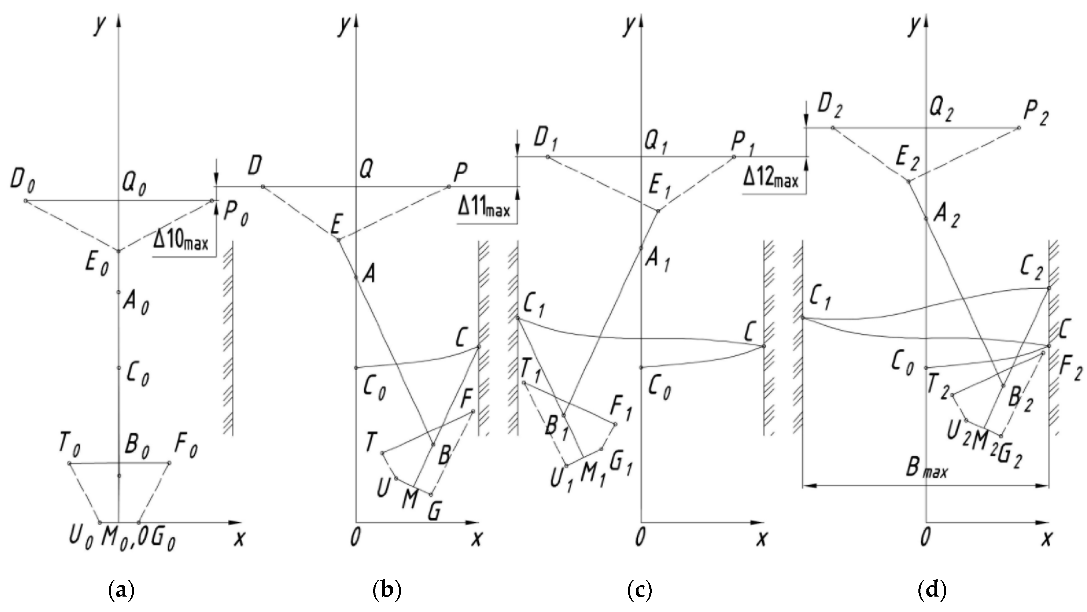
the soil will be excavated with shavings of constant thickness provided that the motion trajectories of the soil-digging symmetrical actuator in the face for each half-cycle of oscillating motion are parallel to each other regardless of the speed values Vs and Vl.m.
-
the trajectory of the symmetrical-actuator motion in the face can be adjusted by additional rotation of the intermediate frame at the end of each half-cycle of reciprocating (oscillating) motion of the symmetrical actuator.
-
the duration and value of the symmetrical-actuator advance supply to the face at the end of each half-cycle are determined by the stability of the Vs/Vc ratio.
-
the patterns of the actuator motion in a wide face that satisfy the above-mentioned conditions can be determined.
Soil excavation by the universal-earthmoving-vehicle actuator is provided by a combination of the processes of cutting the soil due to the rotor rotation 1 (Figure 2) and the actuator-supply motion to the face. It is provided by moving the vehicle along the excavation with a speed Vc and the lateral (oscillating) motion of the actuator with a speed Vl.m.
The supply motion of the cutting edge of the rotor buckets 1 (Figure 4) is formed by a lever mechanism, the design of which is described above, and it is the result of:
-
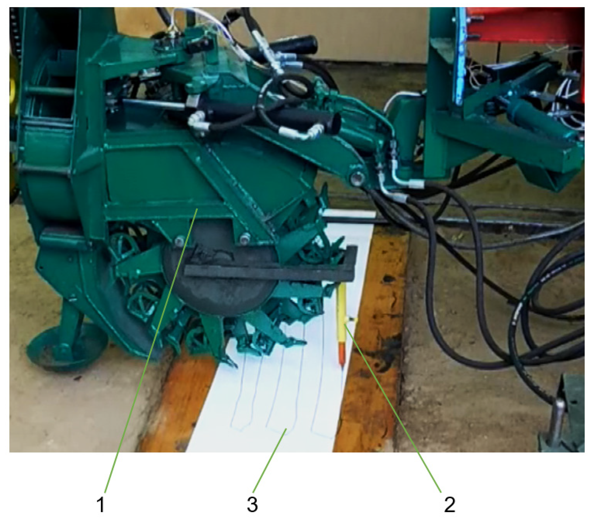
direct motion of the squaring plate 4 of the base chassis stern.
-
rotational (oscillating) motion of the intermediate frame 3 relative to the plate 4, provided by the motion of the hydraulic cylinder rods 7 and 8.
-
rotational (oscillating) motion of the actuator frame 2 together with the rotor 1 relative to the frame 3, which is the result of the motion of the hydraulic cylinder rods 5 and 6.
Thus, the rotor supply mechanism is a flat lever with three degrees of ambiguity.
The calculation scheme for determining the position of the cutting periphery of the rotor bucket 1 (point C) is located in a rectangular coordinate system xy (Figure 5). Point 0 (Figure 5a) coincides with the point M of the actuator frame.
The development of the algorithm for determining the trajectory of point C is divided into three stages. The first stage considers the transition of the mechanism from the initial position corresponding to the longitudinal axis of the vehicle (Figure 5a)—here, the characteristic points have the index “0”—to the extreme right position near the side wall of the excavation (Figure 5b). The second stage implies the transition of the mechanism from the extreme right to the extreme left position (Figure 5c); here, the characteristic points are given the index “1”. The third stage is characterized by the transition of the mechanism from the extreme left position near the side wall of the groove to the extreme right position (Figure 5d), which is near the opposite wall of the excavation in the soil; here the index of the characteristic points is denoted by “2”. At the first stage, the characteristic points did not have an index.
To simplify the calculation of the characteristic points of the mechanism in its lateral motion when digging the soil, the operator functions have been used [4]. The operator function is an expression of F (x1, x2xn; y1, y2yn), where F is a function name and xi and yi are input and output parameters, respectively.
The operator function M1(a, b, R1, c, d, R2; x1, x2, y1, y2) determines the coordinates of the intersection points of two circles: radius R1 from the center with coordinates (a, b) and radius R2 from the center with coordinates (c, d). The equation of the two circles is:
( x a ) 2 + ( y b ) 2 = R 1 2 ; y 1 , 2 = k 4 ± k 4 2 4 k 3 k 5 2 k 3 .
The circles intersect at points 1 and 2, the coordinates of which are equal to:
x 1 , 2 = k 2 + k 1 k 4 ± k 4 2 4 k 3 k 5 2 k 3 ; y 1 , 2 = k 4 ± k 4 2 4 k 3 k 5 2 k 3 ,
where
k 1 = b d c a ; k 2 = a 2 + b 2 R 1 2 c 2 d 2 + R 2 2 2 ( a c ) ; k 3 = ( b d c a ) 2 + 1 ; k 4 = 2 ( k 1 k 2 a k 1 b ) ; k 5 = a 2 + b 2 R 1 2 + k 2 2 2 a k 2 .
The operator function M2(xM,yM,xU,yU,LMC;x1,x2,y1,y2) determines the coordinates of the intersection points C1(x1, y1) and C2(x2, y2) of the straight line that passes through the point M(xM, yM), which is perpendicular to the straight line that passes through the points U(xU, yU) and M, and the circle centered in point M with radius LMC (Figure 5b). The equations of the function
x x M x U x M = y y M y U y M ; ( x x M ) 2 + ( y y M ) 2 = L M C 2 ,
have solutions; the coordinates of the intersection points of the straight line and the circle are:
x 1 , 2 = x M ± L M C k 6 ; y 1 , 2 = y M ± L M C ( x M x U ) k 6 ( y U y M ) ,
where k 6 = 1 + ( x M x U y U y M ) 2 .
The operator function M3(xA, yA, xB, yB, xQ, yQ, LTF; x1, x2, y1, y2) determines the coordinates of the intersection points F1(x1, y1), F2(x2, y2) of the straight line that is perpendicular to the straight line AB and passes through the point T(xT, yT) and a circle drawn from the point T with radius LTF. The equations of these lines have the form:
y y T = x x T α ; ( x x T ) 2 + ( y y T ) 2 = L T F 2 .
The equation system solution (5) with respect to the coordinates of points F1 and F2 is:
x 1 , 2 = k 9 ± k 9 2 4 k 8 k 10 2 k 8 ; y 1 , 2 = y T x 1 , 2 x T k 7 ,
where k 7 = y B y A x B x A ; k 8 = k 7 2 + 1 ; k 9 = 2 x T ( k 7 2 + 1 ) ; k 10 = x T 2 k 7 2 + x T 2 k 7 2 L T F 2 .
To determine the coordinates of the points U1(x1, y1) and U2(x2, y2) of the straight line intersection passing through the points M(xM, yM) and G(xG, yG), and the circle drawn by the radius LUM from the center M (Figure 5b), the operator function M4(xM, yM, xG, yG, LUM; x1, x2, y1, y2) is applied. The equations of the straight line and the circle make up the system:
x x M x G x M = y y M y G y M ; ( x x M ) 2 + ( y y M ) 2 = L U M 2 .
System solution (7) is:
x 1 , 2 = k 13 ± k 13 2 4 k 12 k 14 2 k 12 ; y 1 , 2 = k 10 x 1 , 2 + k 11 ,
where k 10 = y G y M x G x M ; k 11 = x M y G + y M x G x G x M ; k 12 = 1 + k 10 2 ; k 13 = 2 x M + 2 ( k 11 + y M ) k 10 ; k 14 = x M 2 + ( k 11 y M ) 2 L U M 2 .
The operator function is used to determine the distance between two points: L(x1, y1, x2, y2; L1,2).
There is L 1 , 2 = ( x 1 x 2 ) 2 + ( y 1 y 2 ) 2 .
The study of the lever-mechanism motion of the lateral actuator supply to the face at the first stage is preceded by the determination of: the coordinates of the characteristic points of the rotor frame and the intermediate frame and the elements of their structures A0(xA0, yA0), B0(xB0, yB0), etc.; the lengths of the rigid rods LA0D0, LA0P0, LA0E0, LA0B0, LB0T0, LB0F0, LB0U0, LB0G0, LB0M0; and the positions of the hydraulic-cylinder rods of the revolution mechanism, which are characterized by the distances LP0E0, and LF0G0. Based on design considerations, the maximum allowable rod motions are determined: Δ20max of hydraulic cylinder 7 and Δ30max of hydraulic cylinder 5 (Figure 4).
The calculation of the points in the intermediate positions at the first stage is performed in the cycle i = 1…n, where n is the number of positions.
The rod motion that corresponds to the transition of mechanism from one position to another adjacent position is kΔ2 = Δ20max/n and kΔ3 = Δ30max/n. Meanwhile, the stern of the chassis together with the points D, P and A will move a distance kΔ1 = Δ10max/n. The value of Δ10max is based on the characteristics of the vehicle. The values of the generalized coordinates in the i-th position are: Δ1i = kΔ1·i is the chassis stern motion 4, Δ2i = kΔ2·i is the hydraulic cylinder rod motion 7, and Δ3i = kΔ3·I is the hydraulic cylinder rod motion 5.
For constant values of the abscissa of the points A and P, the ordinates of these points in the i-th position are: yAi = yA0 + Δ1i, yPi = yP0 + Δ1i. The positions of the hydraulic-cylinder rods are determined by the distances LPei = LP0E0 + Δ2i and LFGi = LF0G0 + Δ3i. The sequence of calculations performed at the first stage is shown in Table 1.
When performing calculations in the half-cycle, the position I = j is fixed, for which the xCi coordinate is the closest to the value B/2, where B is the width of the groove in the soil. The value of i = j corresponds to the extreme right position of the mechanism (Figure 5b). The positions of the rods of the hydraulic cylinders 6 and 8, which are characterized by the distances LtUj and LDEj, are the starting points for studying the mechanism motion at the second stage.
The calculation of the point C1 trajectory at the second stage is carried out in the half-cycle i = 1…n. The sequence of calculations is shown in Table 2. The calculation ends at position k, where 1 < k ≤ n and corresponds to the value of the abscissa of the point C1; xC1 ≥ −B/2 (Figure 5c). The values of the coordinates xF1k, yF1k, xG1k, yG1k, points F1 and G1 in the k-th position of the mechanism are the starting points for calculating the C2 point trajectory at the third stage.
At the third stage, the calculation takes place in the half-cycle i = 1…n. The sequence of calculations is shown in Table 3.
The calculation ends at the position m, where the value of the abscissa xC2i of the point C2 is the closest to the value B/2.
The main parameters determining the position of the symmetrical actuator are: the maximum width of the trench bmax = 3.9 m; the distance between the extreme positions of the centers of the cutting edge of the actuator buckets Bmax = 3.2 m; base chassis speed Vt = 0…0.031 m/s; half-cycle time at the maximum trench width tmax = 12.7 s; the stroke of the hydraulic-cylinder rods of the intermediate frame S78 = 0.385 m and the stroke of the hydraulic cylinders of the actuator frame S56 = 0.905 m. When performing the calculations, according to the developed algorithm for moving the actuator in the soil when digging, the limitation of the duration of additional rotation of the actuator intermediate frame is in the range of 0.5–1.1 s. The actuator motion trajectory in a wider range of the duration of the intermediate-frame rotation can be calculated according to the developed algorithm. To reduce the weight of the construction, some elements of the working body can be made of high-strength composite materials [24].
Based on the real model of the earthmoving vehicle, the positions of the characteristic points of the UCEM actuator in the face moving by the lever and double-swivel supply mechanism in the accepted coordinate system (Figure 5) have been defined: A0(0; 3160), B0(0; 640), C0(0; 2115), D0(−1275; 4465), E0(0; 3720), F0(685; 820), G0(265; 0), M0(0; 0), V0(0; 820), P0(1275; 4465), T0(−685; 820), U0(−265; 0) and Q0(0; 4465). Figure 5 shows the trajectories of the characteristic point C of the symmetrical actuator bucket in the face for a half-cycle without any additional rotation of the intermediate frame (a) and with the additional rotation (b).
The analysis of the trajectories (Figure 6a) indicates an asymmetrical (an uneven) distribution of the shaving thickness in the half-cycle (Figure 6a) when digging the soil without any additional rotation of the intermediate frame; the shaving thickness is minimal at the beginning of the half-cycle and it reaches a maximum at its end. The uneven distribution of the shaving thickness determines the inequality of the power load from the external cutting forces on the actuator. To reduce the inequality of the external loads on the actuator, at the end of each half-cycle it is necessary to perform a technological stop of the motion of hydraulic cylinder rods 5 and 6 and the additional rotation of the intermediate frame without changing the duration of the cycle. In this case (Figure 6b), a uniform distribution of the shaving thickness in half cycle is achieved. It leads to a uniform load of the actuator. The non-uniformity of the shaving thickness cut by the actuator in the half-cycle of the operating process, provided that the actuator moves in the face according to the algorithm, is up to 10%.
Experimental studies of the feasibility of the developed algorithm to ensure the required trajectory of the symmetrical-actuator motion in the face when digging the soil with shavings of uniform thickness have been experimentally tested on the operating equipment model (M1:5), using a simulator of the trajectory of the actuator motion (Figure 7).
The discrepancy of the parameters of the motion trajectory that were obtained both experimentally and by calculations do not exceed 12% with a confidence interval of 0.95, which is quite acceptable in the study of the earthmoving machinery [18,23]. When developing the algorithm for the actuator motion, the discrepancy between the results of the theoretical and experimental studies is explained by the failure to take into account the anisotropy of the physical and mechanical properties of the excavated soil, as well as by the accuracy of the measuring and recording equipment.

4. Discussion

As a result of the work performed, the practical possibility and expediency of leveling the thickness of shavings cut off by the rotary working body of a universal earthmoving machine, and hence the magnitude of external loads, due to the layout of its hinge at the rear of the base chassis using a double-lever, double-hinged mechanism, has been substantiated. The indicated linkage scheme and its research make it possible to carry out an individual hydrostatic drive of each lever (link) of the mechanism from one common hydraulic pump for both drives. The implementation of the developed algorithm for the movement of the soil-cultivated working body in the process of digging the soil using the effect of turning the intermediate frame at the end of each half-cycle of the working process, adaptive to the value of the actual feed rate of the working body Vs, makes it possible to equalize both the thickness of the soil cut that is off during the digging process as well as the values of the external loads on the working body. The ability to excavate the soil with shavings of constant thickness, rather than variable thickness, doubles the productivity of the machine.
The creation of universal continuous earthmoving machines using a two-lever, two-hinged scheme for the attachment of working equipment at the stern of the base chassis and the development of a workflow-control algorithm make it possible to replace a number of specialized continuous earthmoving machines with one universal machine.
The machine is designed for digging out lengthy cuts in the soil of different widths (from 0.6 to 4.5 m) for various technological purposes, namely trenches for the construction of pipe transport communications, communication lines, drainage, irrigation canals, and special earthworks.

5. Conclusions

The advantages and prospects have been determined for the creation of a universal earthmoving vehicle (UCEM) that is capable of digging long grooves of various linear dimensions in soils of different structure by using a special two-lever mounting mechanism of their rotor actuators on the base chassis. It is possible instead to use a single-lever, which enables the digging of the soil with shavings of uniform thickness and, as a consequence, to reduce and equalize external loads on the actuator.
Reducing the dynamics of the external loads on the symmetrical actuator when digging the soil and improving the productivity of the vehicle is achieved by equalizing the thickness of the excavated shavings.
The thickness of the excavated shavings is aligned by the additional rotation of the intermediate frame of the actuator at the end of each half-cycle. Its duration is directly proportional to the speed of the vehicle motion. The alignment-accuracy error does not exceed 10%.
The shaving thickness is aligned by implementing the developed algorithm for the symmetrical-actuator motion in the face with the help of two pairs of hydraulic cylinders operating according to this algorithm. The discrepancy between the calculated motion trajectory and experimentally determined one does not exceed 12% with a confidence interval of 0.95.
The creation of universal continuous earthmoving machinery will increase the speed of earthwork, increase mass production, reduce the range of machinery produced and reduce the cost of its manufacture.

6. Patents

Patent for invention № 101931 Ukraine, MPK (2013.01) E02F 3/00. Universal earthmoving machine/M.F., Dmytrychenko; V.D., Musiiko; M.O., Bilyakovych; Yu.B., Leichenko; A.B., Koval; M.P. Kuzminets; Owner National Transport University;—№ a 2012 09065; submitted 23.07.2012; published 13.05.2013, Bul. № 9.
Patent for invention № 114779 Ukraine, MPK (2017.01) E02F 3/00. Universal earthmoving machine /M.F., Dmytrychenko; V.A. Demyanuk, V.D., Musiiko; M.O., Bilyakovych; Yu.B., Koval; Yu.V. Lazaruk, I.O. Teslenko; Owner National Transport University;—№ a 2016 009428; submitted 12.09.2016; published 10.02.2017, Bul. № 3.

Author Contributions

Conceptualization, V.M., M.H., P.Š.; methodology, V.M., V.N., J.L.; software, V.N., A.S., J.L.; validation, M.H., V.N., A.K.; formal analysis, M.H., J.L.; investigation, M.H., V.N., A.S., P.Š., A.K.; resources, M.H., V.N., J.L.; writing—original draft preparation, J.L., A.S.; writing—review and editing, V.M., A.K., P.Š.; visualization, V.N., A.S., J.L.; supervision, V.M., P.Š., A.K. All authors have read and agreed to the published version of the manuscript.

Funding

This publication was realized with support of Operational Program Integrated Infrastructure 2014–2020 of the project: Innovative Solutions for Propulsion, Power and Safety Components of Transport Vehicles, code ITMS 313011V334, co-financed by the European Regional Development Fund.

Data Availability Statement

Not applicable.

Conflicts of Interest

The authors declare no conflict of interest.

Nomenclature

UCEMUniversal continuous earthmoving machine
PZM-1Earthmoving machines
PZM-2Earthmoving machines
BWidth of the excavation
VsSpeed of supplying the actuator to the face
VcSoil cutting speed
Vl.m.Speed of the lateral supply of the actuator to the face
VhStem extension speed of the hydraulic cylinder (4) (Figure 3) of the intermediate-frame rotation
V’hStem extension speed of the hydraulic cylinders (5) (Figure 3) of the actuator-frame rotation
βAngle of the intermediate-frame rotation
φRotor-frame rotation angle
F(x1, x2xn; y1, y2yn)Operator function
xiInput parameters
yiOutput parameters
M1(a, b, R1, c, d, R2; x1, x2, y1, y2) Operator function determines the coordinates of the intersection points of two circles
R1Radius from the center with coordinates (a, b)
R2Radius R2 from the center with coordinates (c, d)
M2(xM,yM,xU,yU,LMC;x1,x2, y1,y2) Operator function determines the coordinates of the intersection points C1(x1, y1) and C2(x2, y2) of the straight line passing through the point M(xM, yM) perpendicular to the straight line passing through the points U(xU, yU) and M, and the circle centered in point M
LMCRadius by Figure 5b
k1, k2, k3, k4, k5, k6,k7, k8, k9, k10, k11, k12,k13, k14,Coefficients
M3(xA, yA, xB, yB, xQ, yQ, LTF; x1, x2, y1, y2) Operator function determines the coordinates of the intersection points F1(x1, y1), F2(x2, y2) of the straight line passing through the point T(xT, yT), perpendicular to the straight line AB, and a circle drawn from the point T with radius LTF.
LTFRadius drawn from point T
M4(xM, yM, xG, yG, LUM; x1, x2, y1, y2) Operator function to determine the coordinates of the points U1(x1, y1) and U2(x2, y2) of the straight line intersection passing through the points M(xM, yM) and G(xG, yG), and the circle drawn by the radius LUM from the center M
LUMRadius from the center M
L(x1, y1, x2, y2; L1,2) Operator function is used to determine the distance between two points
LA0D0, LA0P0, LA0E0, LA0B0, LB0T0, LB0F0, LB0U0, LB0G0, LB0M0Lengths of rigid rods
LP0E0, and LF0G0Distances that characterize the positions of the hydraulic cylinders rods of the revolution mechanism
A0(xA0, yA0), B0(xB0, yB0)Coordinates of the characteristic points of the rotor frame and the intermediate frame and elements of their structures
Δ20maxMaximum allowable rod motions of hydraulic cylinder 7 (Figure 4)
Δ30maxMaximum allowable rod motions of hydraulic cylinder 5 (Figure 4)
nNumber of positions
kΔ2, kΔ3Rods motion that corresponds to the transition of mechanism from one to another adjacent position
kΔ1Distance of the move of the chassis stern
Δ1iChassis stern motion 4
Δ2iHydraulic cylinder rod motion 7
Δ3iHydraulic cylinder rod motion 5
LTUjDistances that characterize the positions of the rods of the hydraulic cylinders 6
LDEjDistances that characterize the positions of the rods of the hydraulic cylinders 8
bmaxMaximum width of the trench
BmaxDistance between the extreme positions of the centers of the cutting edge of the actuator buckets
VtBase chassis speed
tmaxHalf-cycle time at the maximum trench width
S78Stroke of the hydraulic cylinder rods of the intermediate frame
S56Stroke of the hydraulic cylinders of the actuator frame
ΔShaving thickness in the half-cycle

References

  1. Gerlici, J.; Yefymenko, A.; Kravchenko, A.; Kravchenko, K. The stability analysis of two-wheeled vehicle model. MATEC Web Conf. 2018, 15714, 01007. [Google Scholar] [CrossRef]
  2. Gorbunov, M.; Gerlici, J.; Kara, S.; Nozhenko, O.; Chernyak, G.; Kravchenko, K.; Lack, T. New principle schemes of freight cars bogies. Manuf. Technol. 2018, 18, 233–238. [Google Scholar] [CrossRef]
  3. Gerlici, J.; Gorbunov, M.; Nozhenko, O.; Pistek, V.; Kara, S.; Lack, T.; Kravchenko, K. About creatiion of bogiie of the freiight car. Commun.-Sci. Lett. Univ. Zilina 2017, 19, 29–35. [Google Scholar]
  4. Musiiko, V.D.; Koval, A.B. Theory and Creation of Innovative Continuous Earthmoving Vehicle, 2nd ed.; Publishing house Lyudmyla: Kiev, Ukraine, 2018; 282p. [Google Scholar]
  5. Blatnický, M.; Dižo, J.; Timošcuk, M. Design of a three-finger robot manipulator. Manuf. Technol. 2016, 16, 485–489. [Google Scholar] [CrossRef]
  6. Sága, M.; Blatnický, M.; Vaško, M.; Dižo, J.; Kopas, P.; Gerlici, J. Experimental determination of the manson−coffin curves for an original unconventional vehicle frame. Materials 2020, 13, 4675. [Google Scholar] [CrossRef]
  7. Quan, Z.; Ge, L.; Wei, Z.; Li, Y.W.; Quan, L. A Survey of Powertrain Technologies for Energy-Efficient Heavy-Duty Machinery. Proc. IEEE 2021, 109, 279–308. [Google Scholar] [CrossRef]
  8. Brodny, J.; Alszer, S.; Krystek, J.; Tutak, M. Availability analysis of selected mining machinery. Arch. Control. Sci. 2017, 27, 197–209. [Google Scholar] [CrossRef] [Green Version]
  9. Bravo, R.; Ortiz, P.; Molina, J. Modelling initial motion of non-spherical sediment particles on inclined and seeped beds. Appl. Math. Model. 2021, 96, 678–696. [Google Scholar] [CrossRef]
  10. Kudra, S.E.; Bykov, A.V. Chain-and-girder working body of the universal earthmoving car. Constr. Road Cars 1979, 12, 6–7. [Google Scholar]
  11. Strel’nikov, A.N. Determination of Rational Operating Modes of Chain Trench Excavators with a Scraper Working Body. Ph.D. Thesis, The Siberian State Automobile and Highway University (SibADI), Omsk, Russia, 2003; 19p. [Google Scholar]
  12. Vetrov, Y.A.; Baladinskij, V.P. Special Excavation Machines; High School: Kiev, Ukraine, 1980; 192p. [Google Scholar]
  13. Sokolski, M. Mining Machines and Earth-Moving Equipment: Problems of Design, Research and Maintenance; Springer International Publishing: Cham, Switzerland, 2019; pp. 1–226. [Google Scholar]
  14. Bykov, A.B. The Study of the Structural and Kinematic Parameters of the Chain and Bar Actuator of a Universal Earth-Moving Vehicle. Ph.D. Thesis, Kharkov Automobile Road Institute, Kharkiv, Ukraine, 1986; 205p. [Google Scholar]
  15. Lu, J.; Bi, Q.; Li, Y.; Li, X. Estimation of fill factor for earth-moving machines based on 3D point clouds. Meas. J. Int. Meas. Confed. 2020, 165, 108114. [Google Scholar] [CrossRef]
  16. Yang, Y.; Long, P.; Song, X.; Pan, J.; Zhang, L. Optimization-Based Framework for Excavation Trajectory Generation. IEEE Robot. Autom. Lett. 2021, 6, 1479–1486. [Google Scholar] [CrossRef]
  17. Luengo, O.; Singh, S.; Cannon, H. Modeling and identification of soil-tool interaction in automated excavation. IEEE Int. Conf. Intell. Robot. Syst. 1998, 3, 1900–1906. [Google Scholar]
  18. Demyanyuk, V.A.; Musiiko, V.D.; Koval, A.B. Synthesis of the algorithm for operating the universal earthmoving vehicle with a linear trajectory of cutting the soil perpendicular to the axis of the tractor. Sci. Tech. Collect. 2016, 1, 153–164. [Google Scholar]
  19. Bandurov, V.; Syrovchenko, I. Features of work on a regimental earth-moving car. Tech. Armament 1974, 2, 31. [Google Scholar]
  20. Mednikov, A.; Bykov, A. Features of work on a regimental earth-moving car (EMC-2). Tech. Armament 1981, 4, 22–23. [Google Scholar]
  21. Dombrovsky, M.H. Multi-Bucket Excavators. Design, Theory and Calculation; Mechanical Engineering: Moscow, Russia, 1972; 432p. [Google Scholar]
  22. Fedorov, D.I. Actuators of Earthmoving Vehicle; Mechanical Engineering: Moscow, Russia, 1977; 288p. [Google Scholar]
  23. Harbuzov, Z.Y.; Ilgisonis, V.K.; Mutushev, H.A.; Naret, G.B.; Podborsky, L.E.; Uspensky, B.P.; Podborsky, L.E. Continuous Earthmoving Machinery; Mechanical Engineering: Moscow, Russia, 1965; 275p. [Google Scholar]
  24. Balovnev, V.I. Modeling the Processes of Environmental Interaction of Road Construction Vehicle Actuators; High School: Moscow, Russia, 1981; 335p. [Google Scholar]
  25. Kravets, S.; Suponyev, V.; Goponov, A.; Kovalevskyi, S.; Koval, A. Determination efficient operating modes and sizes of blades for multi-scrapertrench excavators. East.-Eur. J. Enterp. Technol. 2020, 4, 23–28. [Google Scholar]
  26. Kyrychenko, I.H. Modular Concept for Designing Technological Vehicle in the Construction Industry; KhNARU: Kharkov, Ukraine, 2002; 120p. [Google Scholar]
  27. Khmara, L.A. Trends in the improvement of specialized earthmoving equipment for tractors and excavators. Intensif. Oper. Processes Constr. Veh. Collect. Sci. Pap. 2002, 15, 4–27. [Google Scholar]
  28. Shatskiy, A.S. On the state of mechanization of pipeline construction. Pipeline Transp. 2007, 4, 10–14. [Google Scholar]
  29. Rudachenko, A.V.; Shmurygin, V.A.; Krets, V.H. Vehicle and Equipment for Gas and Oil Pipelines: Textbook; TPU Publishing House: Tomsk, Russia, 2013; 376p. [Google Scholar]
  30. Dombrovsky, N.H.; Tsipursky, I.L. Specific resistance to digging of foreign rotor trench excavators. Constr. Road Veh. 1969, 8, 7–9. [Google Scholar]
  31. Dombrovsky, N.H.; Tsipursky, I.L. Specific digging effort developed by chain trench excavators. Proc. Univ. 1970, 1, 15–17. [Google Scholar]
  32. Smetanka, L.; Gerlici, J.; Lack, T.; Pelagic, Z. Homogenization of fibers reinforced composite materials for simulation analysis. Manuf. Technol. 2015, 15, 914–920. [Google Scholar] [CrossRef]
Figure 1. The scheme of pit development: (a) view in plan; (b) cross-section area of the excavation.
Symmetry 14 00051 g001
Figure 2. Universal earthmoving vehicle: (a) the scheme of fitting the actuator on the base chassis; (b) the scheme of developing a wide excavation (pit); 1—base chassis; 2—intermediate frame; 3—symmetrical actuator; 4—hydraulic cylinders of the intermediate-frame rotation; 5—hydraulic cylinders of the actuator-frame rotation; 6—mounting hinge of the intermediate frame; 7—mounting hinge of the actuator frame.
Symmetry 14 00051 g002
Figure 3. Kinematic diagram of the actuator links motion when digging the soil: 1—base chassis; 2—intermediate frame; 3—symmetrical actuator; 4—hydraulic cylinders of the intermediate-frame rotation; 5—hydraulic cylinders of the actuator-frame rotation; 6—mounting hinge of the intermediate frame; 7—mounting hinge of the actuator frame; B—width of the excavation; Vs—the speed of supplying the actuator to the face; Vc—soil cutting speed; Vl.m.the speed of the lateral supply of the actuator to the face; Vh—stem extension speed of the hydraulic cylinder (4) of the intermediate-frame rotation; V’h—stem extension speed of the hydraulic cylinders (5) of the actuator-frame rotation; φ—rotor-frame rotation angle.
Symmetry 14 00051 g003
Figure 4. Block diagram of the actuator supply mechanism: 1—rotor, 2—actuator frame, 3—intermediate frame, 4—squaring plate of the base chassis stern, 5, 6, 7, 8—hydraulic cylinders.
Symmetry 14 00051 g004
Figure 5. Calculation schemes of the mechanism.
Symmetry 14 00051 g005
Figure 6. The trajectory of the point C in the coordinates of its motion and xCi, yCi and the shaving thickness Δ in the half-cycle: (a,b)—without additional rotation of the intermediate frame; (c,d)—with the additional rotation of the intermediate frame.
Symmetry 14 00051 g006
Figure 7. Experimental equipment during research: 1—physical model of the actuator, 2—simulator of the actuator-motion trajectory, 3—the trajectory of the cutting periphery of the rotor bucket.
Symmetry 14 00051 g007
Table 1. The sequence of calculations of the first stage of the study.
MethodsOperator Function or Mathematical Expression UsedConditions for Selecting Actual Values
Δ1ii·kΔ1 = i·Δ10max/n
Δ2ii·kΔ2 = i·Δ20max/n
Δ3ii·kΔ3 = i·Δ30max/n
yAiyA0 + Δ1i
yPiyP0 + Δ1i
xEi, yEiM1(xPi, yPi, LPEi, xAi, yAi, LA0E0; x1, y1, x2, y2) yEi = max(y1,y2)
xBi, yBiM4(xAi, yAi, xEi, yEi, LA0B0; x1, y1, x2, y2) yBi = min(y1,y2)
xFi, yFiM1(xAi, yAi, LA0F0, xBi, yBi, LB0F0; x1, y1, x2, y2) xFi = max(x1,x2)
xGi, yGiM1(xFi, yFi, LFGi, xBi, yBi, LB0G0; x1, y1, x2, y2) yGi = min(y1,y2)
xMi, yMiM1(xGi, yGi, LM0G0, xBi, yBi, LB0M0; x1, y1, x2, y2) xMi = min(x1,x2)
xCi, yCiM2(xMi, yMi, xGi, yGi, LM0C0; x1, y1, x2, y2) yCi > yMi
Table 2. The sequence of calculations of the second stage of the study.
Object to Be DeterminedOperator Function or Mathematical Expression UsedConditions for Selecting Actual Values
Δ11iΔ11max/n
Δ21iΔ21max/n
Δ31iΔ31max/n
yAiyA0 + Δ1i + Δ11i
LD1E1iLDEj + Δ21i
xE1i, yE1iM1(xDi, yDi, LD1E1i, xA1i, yA1i, LA0E0; x1, y1, x2, y2) yE1i = max(y1,y2)
xB1i, yB1iM4(xA1i, yA1i, xE1i, yE1i, LA0B0; x1, y1, x2, y2) yB1i = min(y1,y2)
xT1i, yT1iM1(xA1i, yA1i, LA0F0, xB1i, yB1i, LB0F0; x1, y1, x2, y2) xT1i < xB1i
LT1U1iLTUj + Δ31i
xU1i, yU1iM1(xT1i, yT1i, LT1U1i, xB1i, yB1i, LB0U0; x1, y1, x2, y2) yU1i < yB1i
xM1i, yM1iM1(xU1i, yU1i, LM0U0, xB1i, yB1i, LB0M0; x1, y1, x2, y2) xM1i > xU1i
xC1i, yC1iM2(xM1i, yM1i, xU1i, yU1i, LM0C0; x1, y1, x2, y2) yC1i > yM1i
xF1i, yF1iM3(xA1i, yA1i, xB1i, yB1i, xT1i, yT1i, LF0T0; x1, y1, x2, y2) xf1i > xT1i
xG1i, yG1iM4(xM1i, yM1i, xU1i, yU1i, LG0M0; x1, y1, x2, y2) xG1i > xM1i
Table 3. The sequence of calculations of the third stage of the study.
Object to Be DeterminedOperator function or Mathematical Expression UsedConditions for Selecting Actual Values
Δ12iΔ11max/n
Δ22iΔ21max/n
Δ32iΔ31max/n
yAiyD1k+ Δ12i
yP2iyD1k+ Δ12i
yA2iyA1k+ Δ12i
LP2E2iLP1E1j+ Δ22i
xE2i, yE2iM1(xP2i, yP2i, LP2E2i, xA2i, yA2i, LA0E0; x1, y1, x2, y2) yE1i = max(y1,y2)
xB2i, yB2iM4(xA2i, yA2i, xE2i, yE2i, LA0B0; x1, y1, x2, y2) yB1i = min(y1,y2)
xF2i, yF2iM1(xA2i, yA2i, LA0F0, xB2i, yB2i, LB0G0; x1, y1, x2, y2) xF2i > xB2i
LF2G2iLF1G1j+ Δ32i
xG2i, yG2iM1(xF2i, yF2i, LF2G2i, xB2i, yB2i, LB0G0; x1, y1, x2, y2) yG2i < yB2i
xM2i, yM2iM1(xG2i, yG2i, LM0G0, xB2i, yB2i, LB0G0; x1, y1, x2, y2) xM2i < xG2i
xC2i, yC2iM2(xM2i, yM2i, xG2i, yG2i, LM0C0; x1, y1, x2, y2) yC2i < yM2i
Publisher’s Note: MDPI stays neutral with regard to jurisdictional claims in published maps and institutional affiliations.

