
Symmetrical Control Law for Chaotization of Platform Vibrations

1
Control of Complex Systems Laboratory, Institute for Problems in Mechanical Engineering of Russian Academy of Sciences (IPME RAS), 61 Bol’shoy Pr. V.O., 199178 Saint Petersburg, Russia
2
Department of Applied Cybernetics, Faculty of Mathematics and Mechanics, Saint-Petersburg State University, Stary Peterhof, Universitetsky Prospekt, 198504 Saint Petersburg, Russia
*
Author to whom correspondence should be addressed.
Symmetry 2022, 14(11), 2460; https://0-doi-org.brum.beds.ac.uk/10.3390/sym14112460
Submission received: 20 September 2022
/
Revised: 4 November 2022
/
Accepted: 10 November 2022
/
Published: 20 November 2022
(This article belongs to the Special Issue Symmetry in Dynamic Systems)
Abstract
:The paper proposes an experimentally validated method of chaotization of the platform movement process based on the principle of feedback control using a symmetrical (bidirectional) controller. The significance is shown and the prospect of chaotization of platform oscillations for vibration technologies, in particular, mixing of bulk materials, is disclosed. The proposed algorithm was comprehensively experimentally studied with a laboratory vibratory setup, and the results of experiments demonstrating its efficacy are presented.
1. Introduction
Vibratory machines and vibration technologies are widely used in many fields of industry and agriculture for influencing materials or products during their movement and processing, such as grinding, sorting, mixing, and compacting; see [1,2,3,4,5,6,7,8,9]. Features of the phenomenon of mixing granular media and technological aspects of this process are discussed in detail in monograph [10]; see also Dolgunin et al. [11]. Chaotization of mixing processes is known as a way of increasing their efficiency; cf. [12,13,14,15]. The idea of random mixing of bulk materials was introduced into industrial practice in machines manufactured by Kroosher Technologies (web page: http://www.kroosh.com/ (accessed 17 November 2022)), Kroosher products contain Kroosher© mechanical device attached to the shaker shaft. Thanks to it, additional vibrations arise, which are mechanically transmitted to the drive of the machine through wear-resistant liners. This vibration technology is based on exposing the bulk material passing through the screen to vibrations with a continuous frequency spectrum. According to their properties, these oscillations can be classified as chaotic. Kroosher justifies his approach by arguing that the use of a narrow-spectrum vibratory agitator may result in the separation of the granular material instead of mixing. Chaotic (multi-frequency) mixing avoids this phenomenon. Thanks to the Kroosher© device, the energy of single-frequency oscillations is redistributed between oscillations with a wide frequency spectrum. The result of this impact is an increase in the efficiency of loosening and mixing of the material. Chaotization of a DC motor for use in industrial mixing processes is presented in [13], where time-delay feedback control was used. As Chau et al. [13] notes, the proposed chaotic motion engine not only provides the desired chaotic mixing but also has high performance and flexible controllability.
Recent publications related to nonlinear dynamic processes, including chaotic ones, in applications in various fields of science and technology, such as the application of chaos to communications, random number generation, game theory, and encryption systems, are reflected in the special issue [16]. In particular, the dynamics of a symmetrical panel absorber fixed on a flexible wall is considered in [17], where the weighted residual elliptic integral method is used. The nonlinear vibration control for suppressing nonlinear oscillations of a self-excited 1DoF system was considered in [18]. It was shown that, when the loop delays are neglected, the performance of the proposed control strategy is proportional to the product of the control and feedback gains and inversely proportional to the internal loop feedback gain. Control of supply chains, subject to control input limitations, was studied by Wang et al. [19]. The control scheme was proposed and equipped with a fixed time disturbance observer and the super-twisting sliding mode algorithm. Chaotic attractors in the closed-loop supply chain system were demonstrated. Schönfeld et al. [20] presented a micromixer based on the consistent use of separation and recombination principles. Mixing characteristics for Reynolds numbers approximately within the interval have been studied, and the numerical results were experimentally confirmed by mixing water–glycerol solutions.
Suzuki et al. [21] presented a magnetic force-driven mixer with a simple configuration, designed to facilitate the mixing of magnetic beads and biomolecules in a microchannel. The mixing device of [21] consists of embedded microconductors as a magnetic field source and a microchannel that guides the streams of the working fluid. Micromixers have found various applications in chemical and biological processes [22]. Chaotic micromixers were studied in [23,24,25,26,27]. A chaotic micromixer with multiple side channels was developed and studied by Niu and Lee [23]. Chaotic mixing in [23] was achieved by stretching and folding the liquid in the main and side channels. Jen et al. [24] designed micromixers with three-dimensional structures of the twisted microchannel to induce chaotic mixing. Kang and Kwon [25] devoted a paper to numerical analysis methods for a detailed understanding of the mixing process in micromixers. The proposed numerical method makes it possible to visualize mixing models and quantify mixing performance in chaotic micromixers. Stremler et al. [26] described an approach to developing microfluidic mixers using chaotic advection. As stated in [26], chaotic advection analysis (“designing for chaos”), based on practical mixer design, is a promising approach in this emerging field.
The unbalanced actuators are the most widely used source for producing oscillations in vibration machines [28,29,30,31,32]. These actuators are used in vibratory conveying machines, lifters, screens, rammers, and many other technologies where circular, elliptical, or directional vibrations are required. Circular vibrations of the working body are generated by a single imbalance or two imbalances rotating synchronously and in phase in the same direction. Gouskov et al. [33], Panovko et al. [34] studied the phenomenon of self-synchronization of a vibratory machine with two actuators driven by two AC induction motors. They discussed the possibility of controlling a resonant vibration machine by correcting the power frequency of vibro-actuators.
This work is devoted to improving the vibratory mixing of granular materials due to the randomization of the movement of the vibrating platform. Unlike in [13], where the drive (electric motor) directly affected the mixing process, in this study, platform vibrations were caused indirectly by the rotation of two unbalanced rotors driven by induction motors. To achieve the goal of the execution of platform movement chaotization of the process, in this paper, the possibility of a phase shift between rotating rotors chaotization is considered, which, in turn, leads to chaotization of the vibrational field of the platform. The symmetrical (bidirectional) control law for drives of the unbalanced rotors is used to obtain the desired phase-shift behavior.
This paper implements the idea expressed in [35,36]: the application of feedback control methods for studying and improving various physical processes, including those in vibration technologies. To do so, advanced vibration setups are being developed in the form of computer-controlled mechatronic complexes. A laboratory model of such a setup, the Multiresonance Mechatronic Laboratory Setup (MMLS) SV-2M of the IPME RAS, was employed in the present study.
The remainder of the paper is organized as follows. In Section 2, a brief description of the laboratory-based mechatronic setup, the SV-2M, is given. The symmetrical control law for the drives of unbalanced rotors is presented in Section 3. Section 4 describes the results of the experimental study. Concluding remarks and future work intentions are given in Section 5.
2. Description of the Laboratory Mechatronic Setup
The MMLS SV-2M is described in detail in a series of papers, including [37,38,39,40]. For the sake of clarity, the SV-2M is briefly described below.
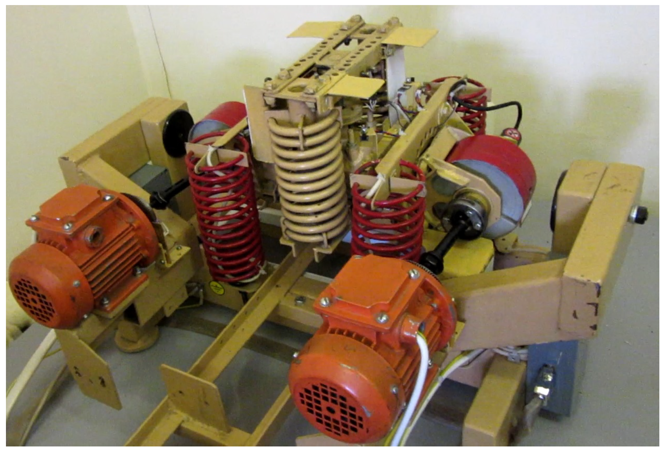
The setup consists of the vibration stand, a pair of induction motors with unbalanced rotors, an electronic converter/amplifier, a sensor unit, and a personal computer (PC). The induction motors can be independently controlled from the side of the PC via the corresponding amplifiers. The imbalance of the rotors is provided by the eccentrically located weights. The rotors are connected to the motor shafts in a vertical plane on the stand base. The mechanical part of the setup is pictured in Figure 1. The positive direction for the “left” (conventionally) motor is clockwise, whereas for the “right” motor it is anti-clockwise.
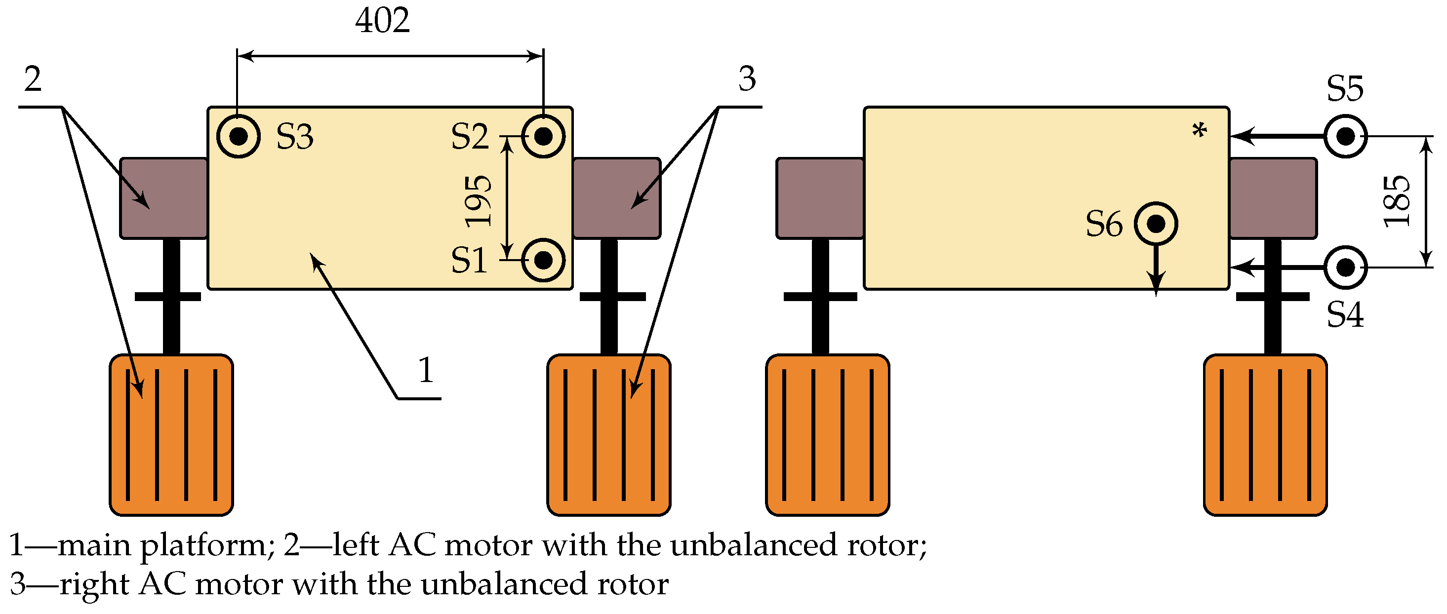
For measuring platforms and rotor angles, the SV-2M is equipped with 12 optical sensors measuring positions of the main and the extra platforms; rotors’ angular sensors with a resolution of 4000 pulses/revolution; the optical motion sensors, DFRobot Smart Grayscale Sensors, making it possible to obtain information about the 6DoF linear and angular coordinates of each platform. Locations of the linear displacement sensors on the main platform are schematically shown in Figure 2.
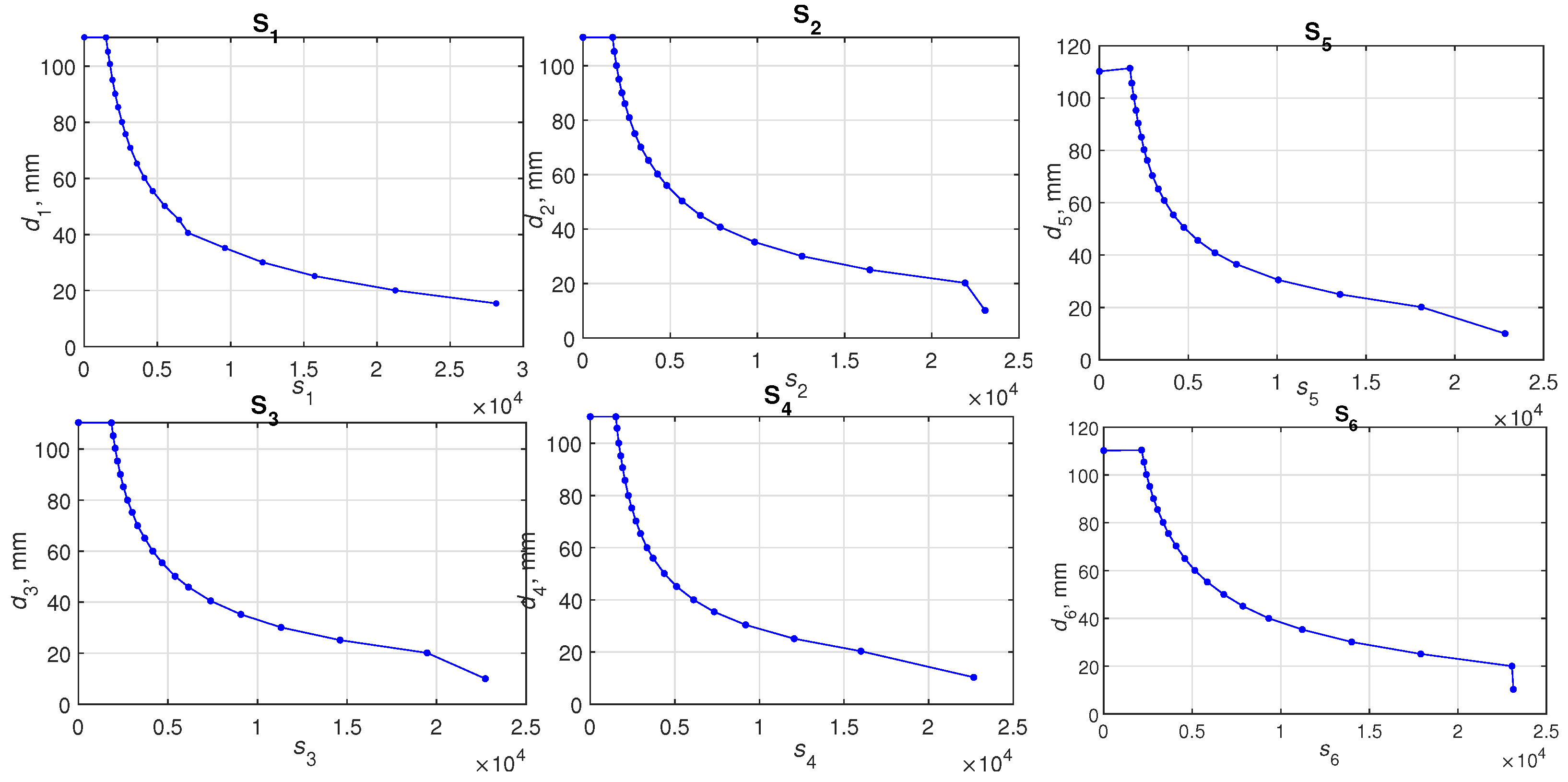
Sensors S–S measure the position of the main platform in the vertical plane, while sensors S–S measure its position in the horizontal plane; sensors S and S make measurements along the x axis, sensor S measures displacement along the y axis. The optical position sensors’ calibration has been performed to obtain their measuring characteristics as mappings from output signals of the digital board driver PCI826 to the distances , . The experimentally taken measuring characteristics of sensors are shown in Figure 3. The measurement nodes’ positions are marked by points; intermediate values were obtained by linear interpolation.
The induction drives are independently controlled by the PC, which forms the governing signals and , setting the rotation speeds of the “left” and “right” drive systems (respectively). These signals are fed to Altivar 12 Schneider Electric converters via a 16-bit DAC in the form of DC voltages in the range of V. The converters have their own local feedbacks, which are used in the “” control mode. The PC outputs are integers in the range , so the dimensionless control signals generated by the PC are non-negative and limited to = 65,535. In the present work, for overloads preventing and ensuring the equipment durability, was set to = 40,000.
Real-time data processing and control-signal generation were carried out by means of Simulink Desktop Real-Time™ of MATLAB© R2015b software with a sampling rate up to 1000 Hz.
3. Symmetrical Control Law for Unbalanced Rotor Drives
3.1. Continuous-Time Symmetrical Control Law
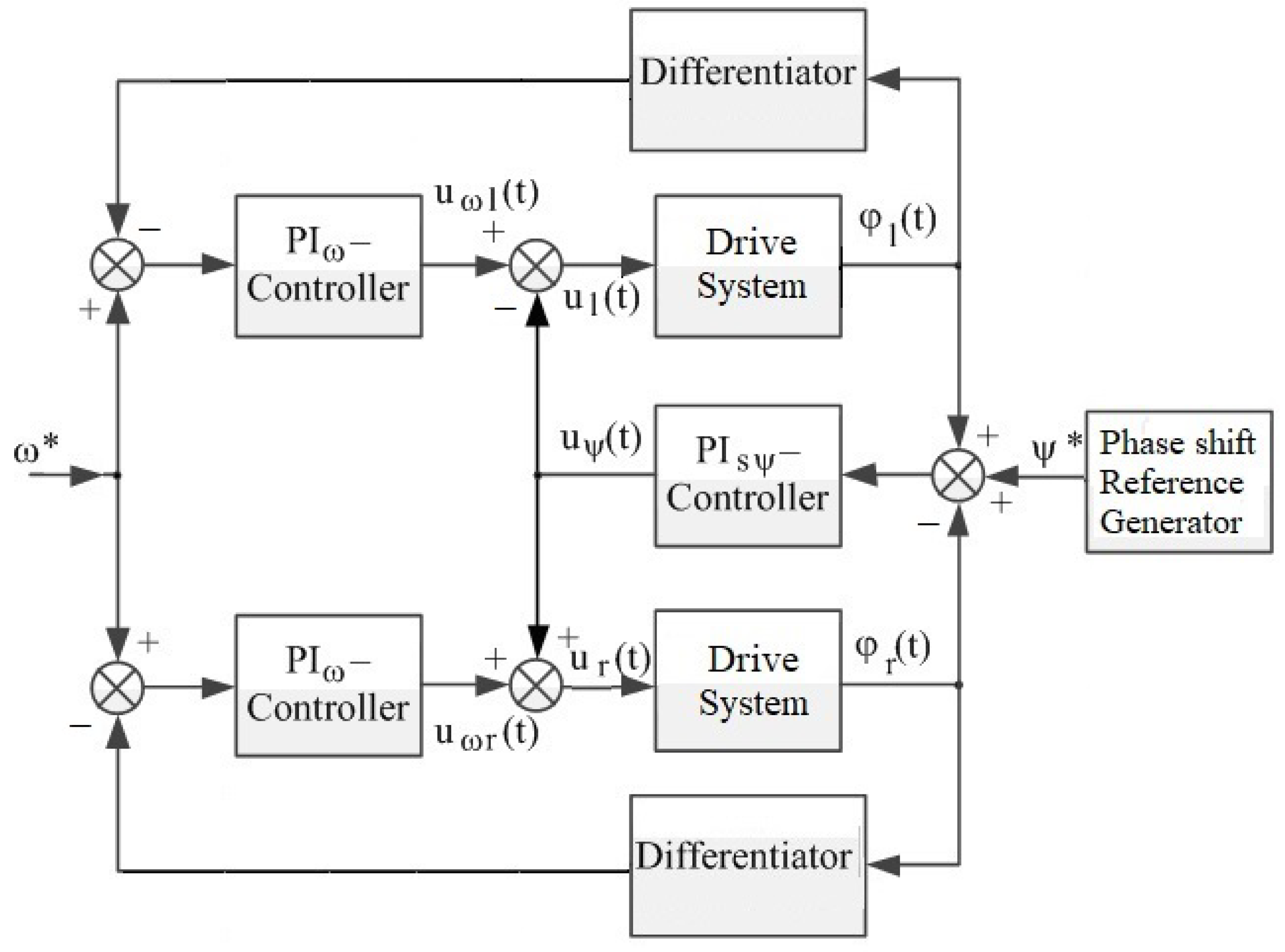
As stated in the Introduction, in the present work for the chaotization of the platform vibrations, the chaotic phase shift was organized by means of the feedback control for the unbalanced rotors drives. To this end, the symmetrical (bidirectional) control law proposed by Andrievsky and Boikov [41] (its adaptive version may be found in [42]) was taken as an initial point. In [40,41], this control law was verified by numerical analysis of the simplified model and the real-world experiments as well. According to this law, the actuators’ velocities were controlled independently of each other by the separated PI controllers, and an anti-symmetrical cross-coupling link was introduced by means of an additional phase-control signal between the control loops, which was generated by the joint PI controller for the phase shift. For the considered aim, the symmetrical PI control law for ensuring the given angular velocity for both rotors and the prescribed phase shift between the rotation angles was as follows:
where denotes the desired rotation velocity; and are the motor’s velocity errors; PI controllers for velocities of the left and right motors are described by (1) and (2), respectively, where and are for the integral, and and are for the proportional controller gains; for the phase-shift PI controller (3), variables and denote the phase angles of the rotors and stands for the phase shift between the rotation angles; the phase shift error is denoted by , where is the prescribed phase shift between the rotors; and in (1) and (2) denote the control signals applied to the left and right drive systems. The block-diagram of symmetrical controller (1)–(3) is depicted in Figure 4.
3.2. Discrete-Time Symmetrical Control Law with Anti-Windup Augmentation
Let us transform control law (1)–(3) into a discrete-time form to be implemented on the controlling PC. Rotation angles and are measured by angular sensors with a certain discretization interval , so that discrete-time values and are obtained as , , where stands for the “discrete time” (the step number). The values of control signals and are generated by the digital controller and then interpolated over the entire sampling interval by zero order hold, so that the continuous-time input signals , of the servo drives are found as , as .
In the system under consideration, the controlling signals, applied to the electric converters, are limited: , and the control laws contain an integration procedure. The control error is integrated by the controller, but when saturation occurs, the controlling input does not change, and the value of the error integral accumulates (there appears, so to speak, a break in the control feedback). This can lead to the emergence of oscillatory or even divergent processes in the system, in which the normal functioning of the system is impossible. This phenomenon is commonly known as “windup”, and measures to prevent it by introducing additional feedback or series compensators are called anti-windup correction (augmentation); see [43,44,45].
The Euler approximation for time derivatives in (1)–(3) results in the following iterative procedure for the host PC:
where function is defined as
The other notations are the same as in (1)–(3). A function is introduced into the control algorithm, since the anti-windup correction only serves to prevent the tracking error accumulation in integrators, but it cannot keep the signals, applied from the digital controller, within the limits . Leaving these signals out of the prescribed area will lead to an erroneous reaction of the converter. It is worth mentioning that no restrictions are imposed on the phase shift controller (6) output .
Remark 1.
In the continuous-time representation, the limited nonlinear dynamic integrator with input , output , and the saturation level is described by the following model:
where ; ∧, ∨ denote the logical “AND” operation.
Following the logic of [46,47], the nonlinear integrator (8) may be approximately described in the Lur’e form as:
where gain is sufficiently large; cf. [47]. Thus, through substituting the limited integrator by approximation (9), one can represent the actuator model in the form of a static saturation with a linear system in a feedback loop. This makes it possible to apply the frequency-domain analysis of [48,49,50] to this kind of system.
3.3. Chaotic Generation of a Reference Phase-Shift Signal
As noted in the Introduction, this work we target carrying out the chaotization of the vibration fields of the working platform through a chaotic change in the phase shift between the angles of rotation of the rotors. For this purpose, the symmetrical phase shift controller, at a fixed (on average) speed of rotation of the rotors, is governed by a phase reference signal generated by a chaotic oscillator. The amplitude and range of the main oscillation frequencies of the generator were selected in accordance with the conditions of the problem. In this work, the Lorentz system (cf. [51,52,53,54]), represented by the following equations, was used as a source of the reference phase-shift signal:
where and c denote the time and output scaling factors, respectively.
4. Experimental Study
This section presents the results of experimental studies on the chaotization of the vibration field of the working platform based on the chaotic change in the phase shift between the rotating rotors.
4.1. Data Acquisition and Preprocessing
As stated in Section 2, rotation angles were measured by optical sensors with a resolution of 4000 pulses/rev. The measured data were sampled in time with a frequency of Hz and were used in PI controllers (4)–(6) to generate control signals and coming from the controlling PC to servos through zero-order hold (ZOH) extrapolation.
The present work is focused on the vibrations of the main platform only. Optical sensors S–S, shown in Figure 2, were used to obtain platform position data. These sensor measurements—the values of respective displacements , were read with a sampling interval and transferred to the PC for converting the sensor readings into the corresponding platform deviations according to their static characteristics. Spline interpolation (function interp1) was used in the MATLAB preprocessing program to restore the values between the nodes, which were tabulated; see [55] for more detail. In the present study, the platform position was not used in the feedback control algorithm (4)–(6); it was aimed only at the post-processing examination of the platform’s motion. The positional sensors’ measurement results were stored in a separate file for further processing. Therefore, sampling time was much less than that of the controller, . Taking into account that the rotors’ revolving speeds can reach 25 rev/s, the value of was chosen as s.
At the next stage of data processing, the values of were cleared of noise and oscillations caused by the movement of other parts of the setup, lying away from the area under study in the vicinity of the fundamental frequency . For this purpose, a filtering procedure based on the fast Fourier transform, implemented by utility fft of MATLAB, was used. Based on the cleared values of , pitch and bank angles and were calculated (in radians) as
where , , and are the deviations (in mm) of , , and with respect to the neutral (initial) values , , and .
To visualize the platform’s oscillations, the trajectories of the platform’s chosen point on the plane were plotted for various time intervals, . As a result of processing, the signal envelopes were also revealed ( was taken as the modulation frequency), and we subsequently calculated their autocorrelation functions. MATLAB utilities amdemod and xcorr are employed to this end.
4.2. Conditions and Parameters for Experimental Study
The following controller parameters were taken for the experiments: s, , , and s. Controller discretization time: s; sampling time of platform position measurements: s. Reference frequency was set to 60 s. The Fourier filters’ bandpass was taken in the vicinity of as s.
Three series of experiments were carried out. In the first of them, -control was not applied—i.e., was set. In the second series, a constant value was taken. In the third one, a Lorentz generator (10) was used as a source of the reference signal . Parameter of (10) was chosen so that variations laid close to the boundaries of radians; time scaling factor was taken based on the available information of the closed-loop system bandwidth with respect to a reference phase shift .
4.3. Control of Rotation
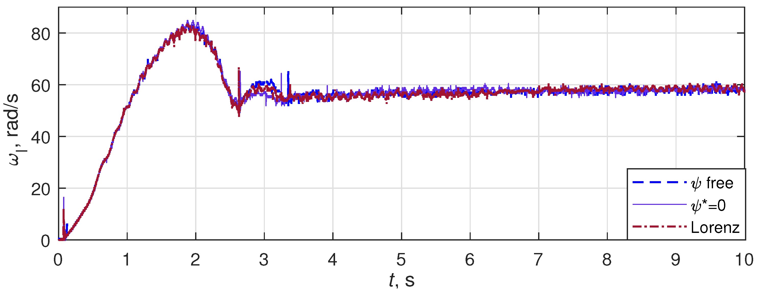
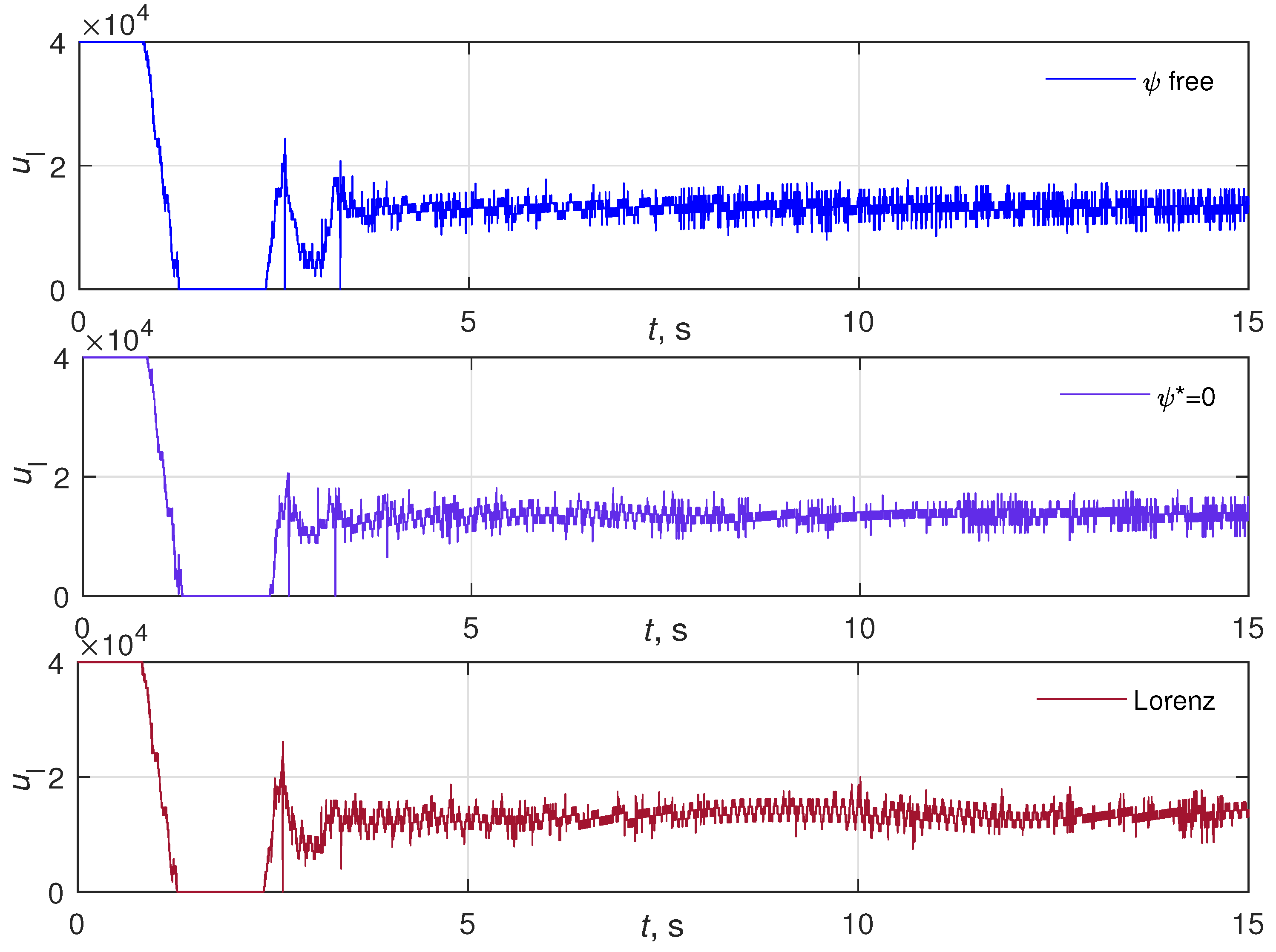
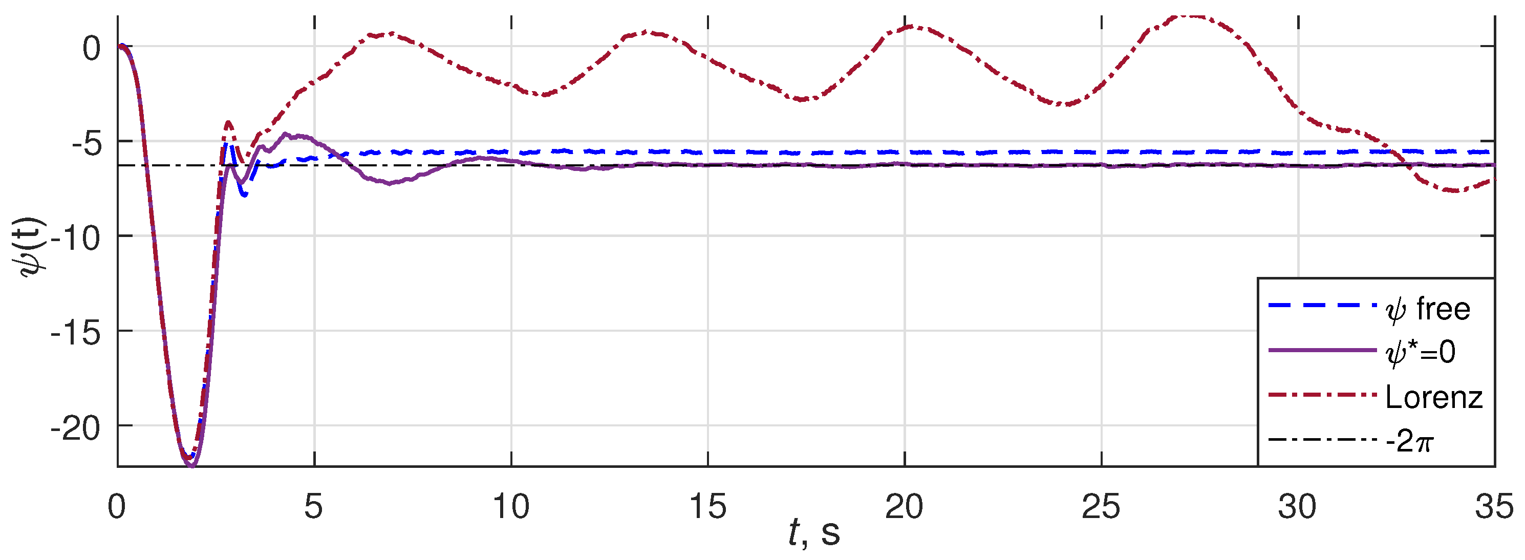
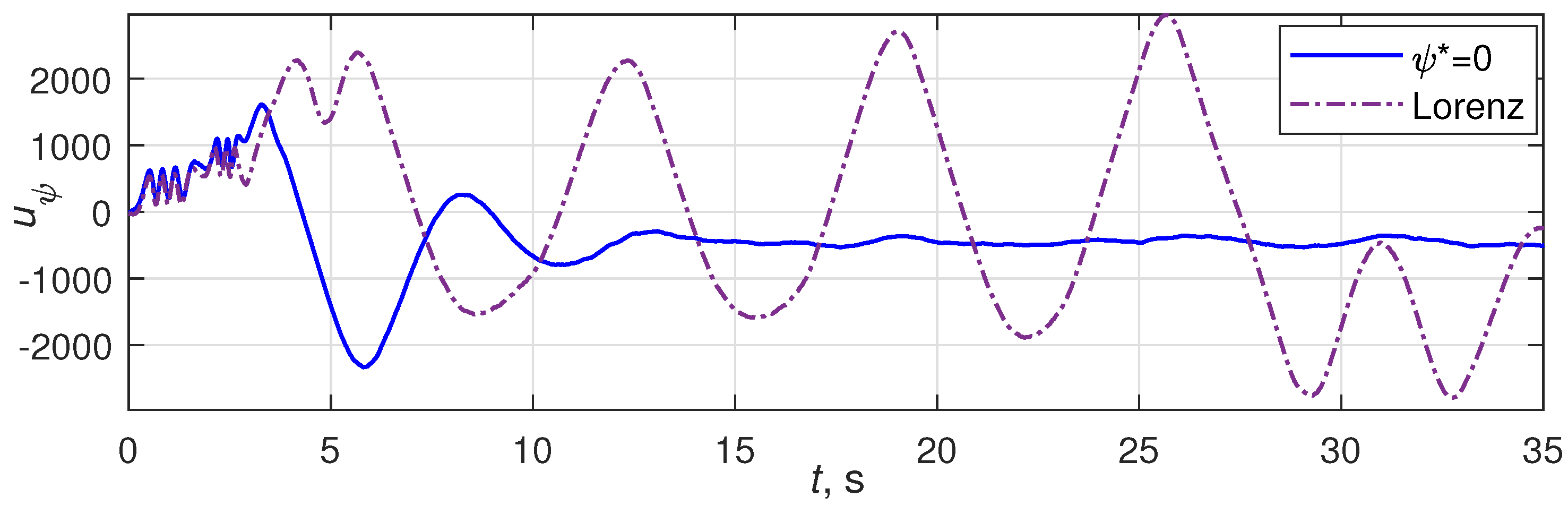
Transients of for cases of free phase shift , , and as the Lorentz generator (10) output are plotted in Figure 7. The corresponding time histories of control signal are depicted in Figure 8. The plots show that for both cases, the transient time of with respect to the 5% zone of the initial error was about 7 s, the overshoot was about %, and the mean steady-state error can be neglected taking into account the usual demands on vibration machines accuracy. It is also seen from Figure 8 that the presence of the phase shift control signal does not make a visible impact on the processes of and , despite that in the second case, changes in a wide range. Time histories of phase shift and control signal for cases of free phase shift , , and as the Lorentz generator (10) output are plotted in Figure 9, Figure 10 (respectively). It can be seen that for the case of , the steady-state error (modulo ) is negligibly small. The steady-state phase shift between the rotors for the case of phase-shift control absence () is close to zero too, demonstrating the self-synchronization effect between rotating debalances; cf. [28,56].
4.4. Platform Motion
Let us now present the results of studying the movement of the main platform of the stand, obtained as a result of the post-processing of experimental data. These studies were aimed at studying the effect of rotation phase-shift chaotization on the platform motion and were aimed at demonstrating that the proposed approach makes it possible to obtain a more diverse, close to chaotic, movement of the platform, and consequently, as noted in the Introduction, it improved the technological properties of the mixing process.
The platform’s movement in the horizontal direction has a significant impact on the behavior of bulk materials; cf. [10,11,28,57]. Experimentally obtained time histories of the platform horizontal coordinate are plotted in Figure 11. The upper plot corresponds to the case of . The case of as a Lorentz generator (10) output is shown on the lower plot. As can be seen in the plots, in the second case, there is a significant, pulsating, change in the nature of the movement of the platform in the horizontal direction.
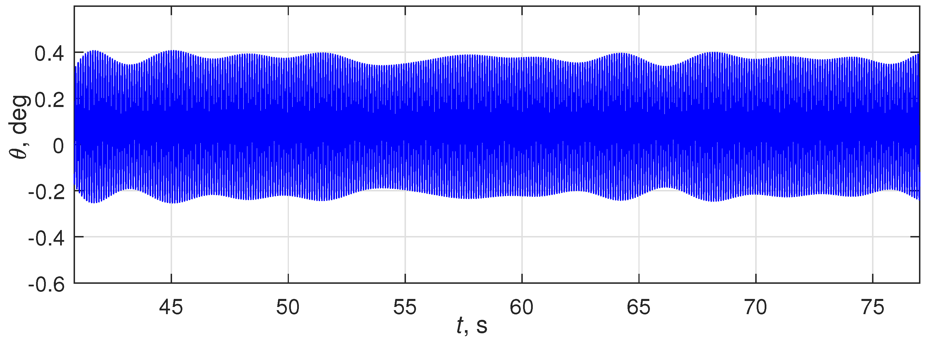
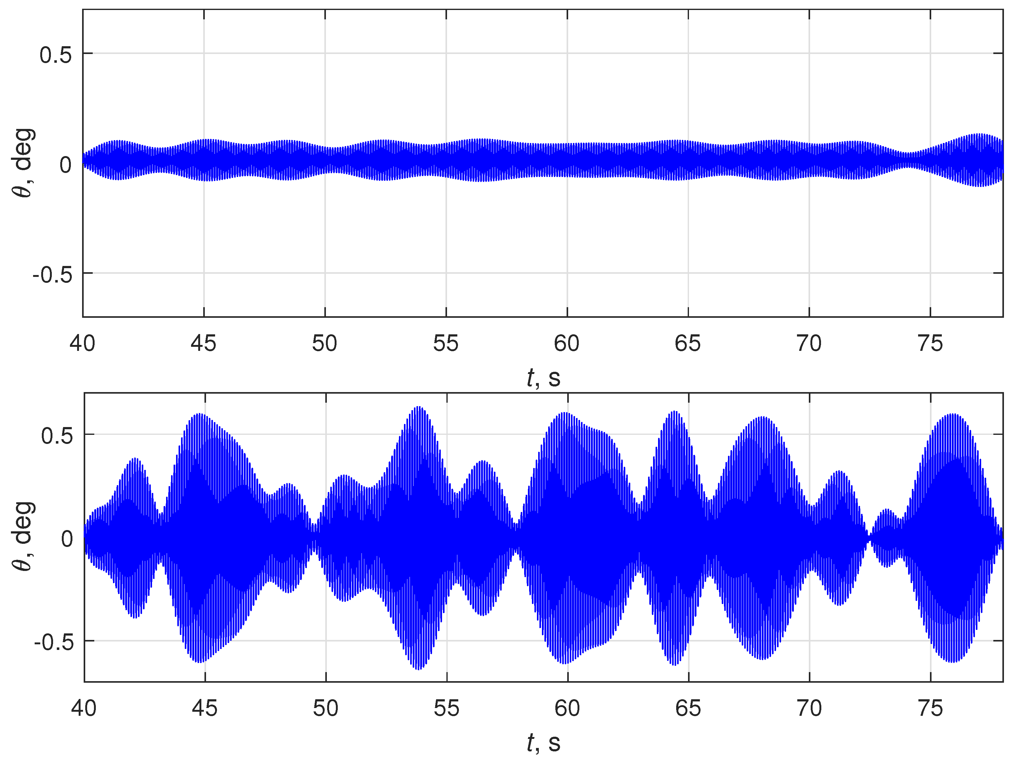
Another important mixing characteristic of the movement of the platform is its inclination—the pitch angle ; see (11). The corresponding plots are shown in Figure 12. The plots demonstrate the pulsating, chaotic nature of this process in the second case, and in the first one the platform oscillates with an almost constant amplitude. In addition, when the phase shift is chaotic, the amplitude of the platform oscillations turns out to be much larger than without it (the graphs are plotted on the same scale). Note that this effect is achieved at practically unchanged average rotation speeds and of the rotors, and also due to a relatively small addition to the control signal, as shown in the plots in Figure 8.
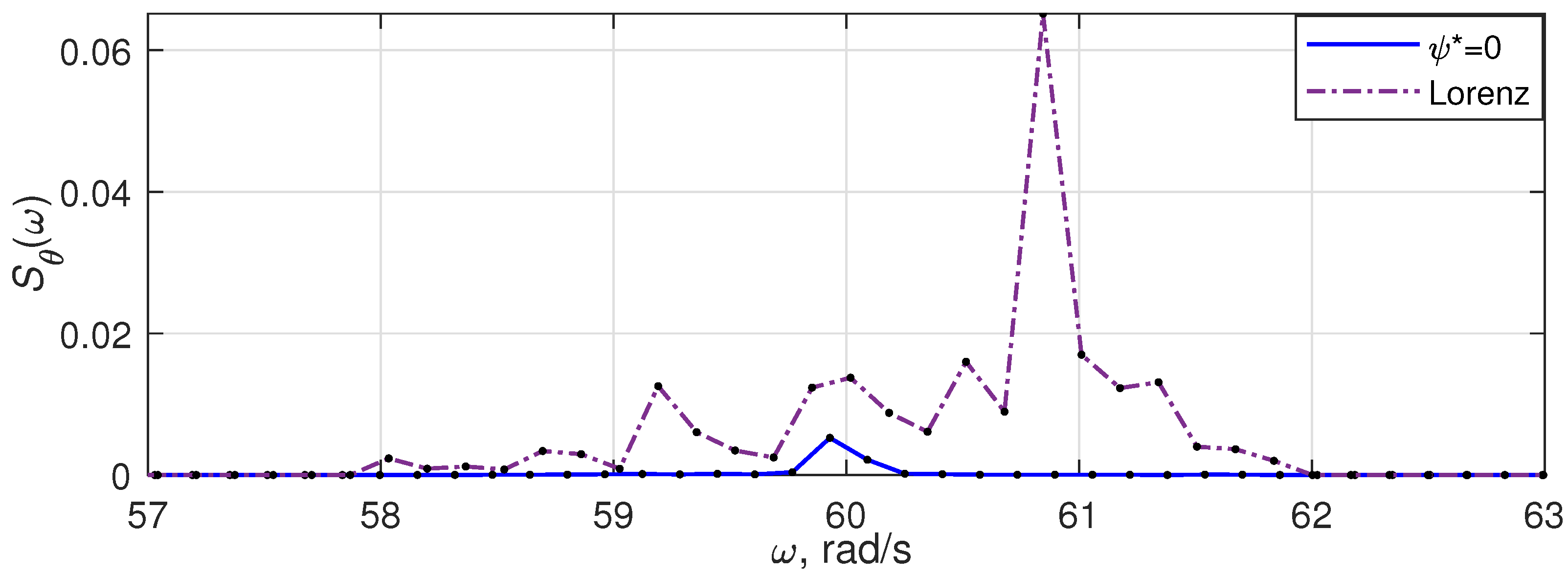
The pitch angle oscillations’ chaotization when using the Lorentz generator as a phase-shift generator is also visible from a comparison of the spectrograms of this process at a fixed (zero) phase shift and a chaotic one, as shown in Figure 13. As can be seen, in the second case, the averaged energy of process is significantly higher, and the carrier band of the signal spectrum is much wider than that in the first case, which also indicates the chaotization of the platform’s oscillations.
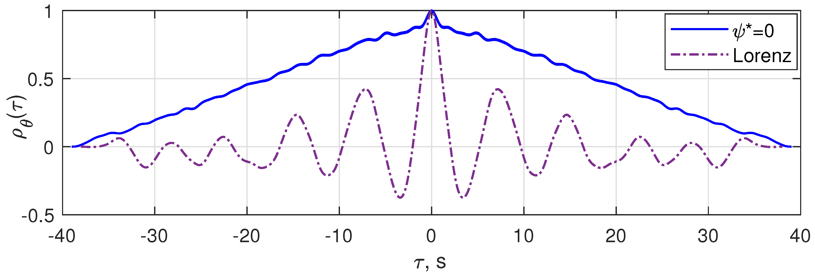
The autocorrelation functions for the process envelope were also obtained. To extract the envelope, the amdemod amplitude demodulation procedure of the MATLAB software was used. Plots of the normalized autocorrelation functions are shown in Figure 14. The relatively faster decay of the autocorrelation function in the second case also indicates the chaotization of the platform angular oscillations.
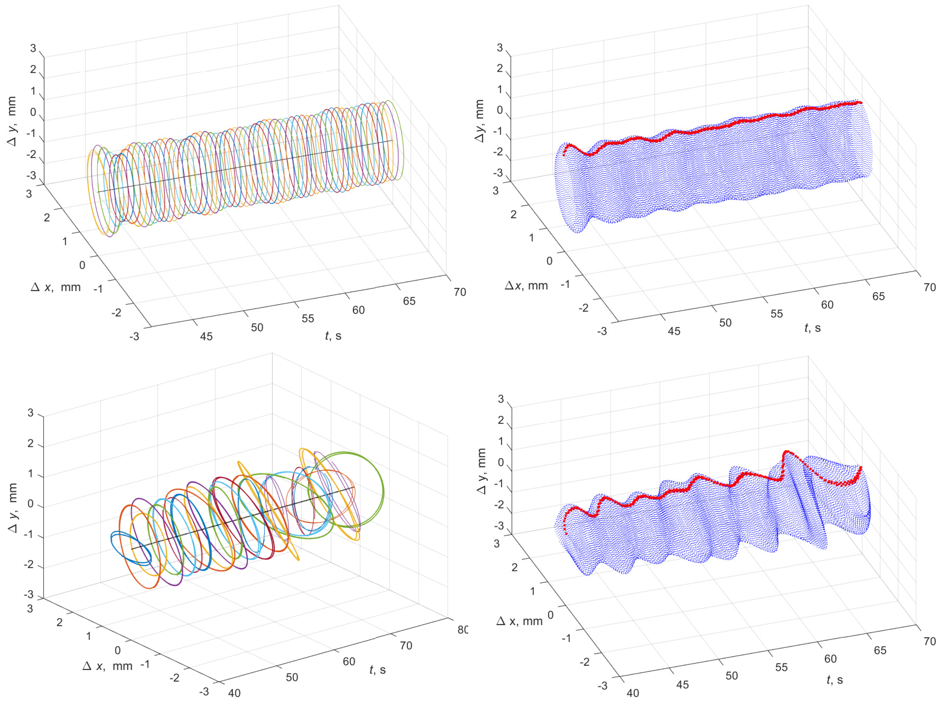
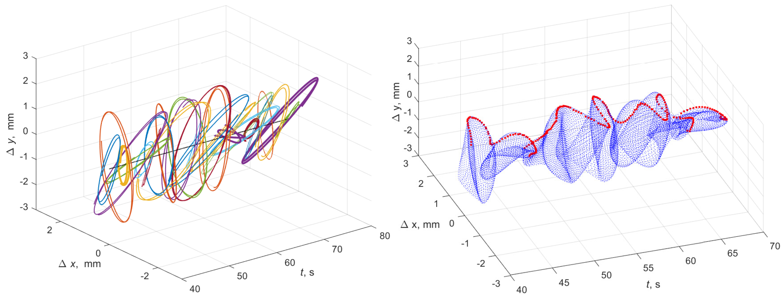
An impression of the process of platform oscillations can be obtained from the analysis of its vibrational fields, represented by the trajectories of movement in time at specific points of the platform. In this study, a point in the upper right corner of the platform (marked with symbol “*”) was taken as this one. The trajectories of its movement in the vertical plane are plotted in the coordinates , corresponding to the longitudinal and vertical displacement relative to the initial (equilibrium) position of the platform.
Figure 15 (upper plots) shows the development of the given point oscillations in time at zero and chaotic phase shift. To do this, the whole time interval of the experimental run was partitioned on subintervals and the corresponding i-th trajectory was plotted in the coordinates . Instants formed the sequence s, and the respective were calculated as s, which approximately corresponds to two oscillation periods for each . For greater clarity, on the lower plots of Figure 15, red dots show the maximum values of the coordinate in each oscillation cycle. As is shown in the graphs, in the second case, the fluctuations turned out to be much more diverse than in the first one.
As is shown in the presented results, the absence of phase control (), or its stabilization at a certain level (), leads to oscillations, which are not enriched by various frequencies; and the use of phase control with variable phase shift, set by a chaotic generator, leads to a variety of platform movement without significant energy costs, and therefore can potentially improve the quality of mixing materials. This result fits well to the concept of changing the oscillating system behavior, by means of the “small” control action; cf. [58,59].
5. Conclusions
Chaotization of vibrations of the platform of a two-rotor vibrating stand was considered. The suggested solution relies on the possibilities of feedback control and modern computer technologies implemented on the mechatronic vibration machine. A digital controller was developed with anti-windup correction, for ensuring the revolving speeds of the unbalance rotors, and simultaneously, the given phase shift between the rotors’ angles. The chaotic Lorentz system was used as a source of the reference signal. The proposed method of chaotization of platform vibrations was implemented and experimentally studied on a laboratory vibration setup, the SV-2M. The results of experiments were presented in the form of graphs of processes, their spectrograms, correlation functions, and patterns of the vibrational field, confirming the efficacy of the proposed chaotization method. From the presented results, it can be seen that the absence of phase control (), or its stabilization at a certain level (), leads to oscillations, which are not enriched by various frequencies. The use of phase control with variable phase shift, set by a chaotic generator, leads to a variety of platform movement without significant energy costs, and therefore can potentially improve the quality of mixing materials. The present work was focused on providing broadband frequency (chaotic) oscillations of the vibration platform, which, under the influence of unbalanced rotors, performs complex oscillatory movements. Oscillations of individual points of the platform differ from each other, creating a “vibration field”, and for the example of the selected point, the results of experiments on the bench using a symmetrical rotor speed controller and the phase angle between them were given. It was found that the proposed method of “chaotization” of oscillations allows, without significant energy costs, a significant complication of platform oscillations, both in amplitude and in direction, which suggests the possibility of using this approach for improving the quality of vibratory mixing of bulk or liquid materials. It is worth mentioning, however, that the important consideration of the behavior of material particles is out of the scope of the present work, and is the subject of further analytical and experimental studies. For example, a situation is possible when a material particle, due to its inertia, volume, and other factors, will vibrate in a petite range of displacements, and not be in chaotic motion. In these studies, it is necessary to take into account the forces of interaction between particles and the platform, the throw coefficient of a granule, the shape of its trajectory when moving on the vibrating table, the type of material, etc. Some useful results on the analysis of particle motion on a vibrating base may be found in [28,57,60,61,62,63,64,65,66,67,68].
To control the speed and a phase shift, in the present study a symmetrical structure with PI controllers modified by the introduction of an anti-windup correction was used. This rather simple structure has proven itself in the problems of controlling the speed and phase shift of the rotating rotors of a vibratory setup; cf. [40,55]. The application of more complex control algorithms in the future is planned, particularly, the adaptive control with an implicit reference model by Andrievsky et al. [42].
Author Contributions
Conceptualization, B.A.; data curation, I.Z.; experimental research, I.Z.; formal analysis, B.A.; funding acquisition, B.A.; Investigation, I.Z.; methodology, B.A.; project administration, B.A.; software, I.Z.; supervision, B.A.; writing—original draft, B.A. and I.Z.; writing—review and editing, B.A. and I.Z. All authors have read and agreed to the published version of the manuscript.
Funding
This work was supported by the Ministry of Science and Higher Education of the Russian Federation (project number 075-15-2021-573, performed in the IPME RAS).
Data Availability Statement
Not applicable.
Acknowledgments
The authors are grateful to Alexander L. Fradkov for some ideas behind the paper and Vladimir I. Boikov for his invaluable work in creating the electronic and computer facilities of the MMLS SV-2M.
Conflicts of Interest
The authors declare no conflict of interest.
Abbreviations
The following abbreviations are used in this manuscript:
| DAC | Digital to Analog Converters |
| MMLS | Multiresonance Mechatronic Laboratory Setup |
| VM | Vibratory Machines |
| PC | Personal Computer |
References
- Andersson, S. Vibrational excitations and structure of CO adsorbed on Ni(100). Solid State Commun. 1977, 21, 75–81. [Google Scholar] [CrossRef]
- Carter, S.; Culik, S.; Bowman, J. Vibrational self-consistent field method for many-mode systems: A new approach and application to the vibrations of CO adsorbed on Cu(100). J. Chem. Phys. 1997, 107, 10458–10469. [Google Scholar] [CrossRef]
- Blekhman, I.I.; Landa, P.S.; Rosenblum, M.G. Synchronization and chaotization in interacting dynamical systems. Appl. Mech. Rev. 1995, 48, 733–752. [Google Scholar] [CrossRef]
- Yang, Z.; Matsumoto, S.; Goto, H.; Matsumoto, M.; Maeda, R. Ultrasonic micromixer for microfluidic systems. Sens. Actuators A Phys. 2001, 93, 266–272. [Google Scholar] [CrossRef]
- Brouwers, H.; Radix, H. Self-compacting concrete: Theoretical and experimental study. Cem. Concr. Res. 2005, 35, 2116–2136. [Google Scholar] [CrossRef]
- Brehl, D.; Dow, T. Review of vibration-assisted machining. Precis. Eng. 2008, 32, 153–172. [Google Scholar] [CrossRef]
- Rowe, W. Principles of Modern Grinding Technology; Elsevier, William Andrew: Amsterdam, The Netherlands; Boston, MA, USA; Heidelberg, Germany; London, UK; New York, NY, USA; Oxford, UK; Paris, France; San Diego, CA, USA; San Francisco, CA, USA; Singapore; Sydney, Australia; Tokyo, Japan, 2009. [Google Scholar]
- Liu, D.; Tang, Y.; Cong, W. A review of mechanical drilling for composite laminates. Compos. Struct. 2012, 94, 1265–1279. [Google Scholar] [CrossRef]
- Chalyj, V.; Moroz, S.; Ptachenchuk, V.; Zablotskyj, V.; Prystupa, S. Investigation of Waveforms of Roller Bearing’s Working Surfaces on Centerless Grinding Operations. In Lecture Notes in Mechanical Engineering; Springer: Cham, Switzerland, 2020; pp. 349–360. [Google Scholar] [CrossRef]
- Dolgunin, V.N.; Ivanov, O.O.; Borshchev, V.Y. Shear Flows of Granular Media: Regularities and Technological Aspects [Sdvigovyye Techeniya Zernistykh Sred: Zakonomernosti i Tekhnologicheskiye Aspekty]; FGBOU VO “TGTU”: Tambov, Russia, 2016. (In Russian) [Google Scholar]
- Dolgunin, V.N.; Ivanov, O.O.; Ukolov, A.A. Segregation kinetics of particles with different roughneses and elasticities under a rapid gravity flow of a granular medium. Theor. Found. Chem. Eng. 2009, 43, 187–195. [Google Scholar] [CrossRef]
- Fradkov, A.L.; Pogromsky, A.Y. Introduction to Control of Oscillations and Chaos; World Scientific Publishers: Singapore, 1998; p. 391. [Google Scholar]
- Chau, K.; Ye, S.; Gao, Y.; Chen, J. Application of chaotic-motion motors to industrial mixing processes. In Proceedings of the 39th IAS Annual Meeting, Record of the 2004 IEEE Industry Applications Conference, Seattle, WA, USA, 3–7 October 2004; Volume 3, pp. 1874–1880. [Google Scholar] [CrossRef]
- Fradkov, A.; Evans, R. Control of chaos: Methods and applications in engineering. Annu. Rev. Control 2005, 29, 33–56. [Google Scholar] [CrossRef]
- Fradkov, A.L.; Evans, R.J.; Andrievsky, B.R. Control of chaos: Methods and applications in mechanics. Philos. Trans. A Math. Phys. Eng. Sci. 2006, 364, 2279–2307. [Google Scholar] [CrossRef]
- Grassi, G. Special Issue Editorial “Chaotic Systems and Nonlinear Dynamics”. Symmetry 2022, 14, 1137. [Google Scholar] [CrossRef]
- Lee, Y.Y. Frequency-Amplitude Relationship of a Nonlinear Symmetric Panel Absorber Mounted on a Flexible Wall. Symmetry 2021, 13, 1188. [Google Scholar] [CrossRef]
- Saeed, N.; Awrejcewicz, J.; Alkashif, M.; Mohamed, M. 2D and 3D Visualization for the Static Bifurcations and Nonlinear Oscillations of a Self-Excited System with Time-Delayed Controller. Symmetry 2022, 14, 621. [Google Scholar] [CrossRef]
- Wang, B.; Jahanshahi, H.; Volos, C.; Bekiros, S.; Yusuf, A.; Agarwal, P.; Aly, A. Control of a symmetric chaotic supply chain system using a new fixed-time super-twisting sliding mode technique subject to control input limitations. Symmetry 2021, 13, 1257. [Google Scholar] [CrossRef]
- Schönfeld, F.; Hessel, V.; Hofmann, C. An optimised split-and-recombine micro-mixer with uniform ‘chaotic’ mixing. Lab Chip 2004, 4, 65–69. [Google Scholar] [CrossRef]
- Suzuki, H.; Ho, C.M.; Kasagi, N. A chaotic mixer for magnetic bead-based micro cell sorter. J. Microelectromech. Syst. 2004, 13, 779–790. [Google Scholar] [CrossRef]
- Nguyen, N.T. Micromixers: Fundamentals, Design, and Fabrication; Elsevier, William Andrew: Amsterdam, the Netherlands; Boston, MA, USA; Heidelberg, Germany; London, UK; New York, NY, USA; Oxford, UK; Paris, France; San Diego, CA, USA; San Francisco, CA, USA; Singapore; Sydney, Australia; Tokyo, Japan, 2008; pp. 1–311. [Google Scholar]
- Niu, X.; Lee, Y.K. Efficient spatial-temporal chaotic mixing in microchannels. J. Micromech. Microeng. 2003, 13, 454–462. [Google Scholar] [CrossRef] [Green Version]
- Jen, C.P.; Wu, C.Y.; Lin, Y.C.; Wu, C.Y. Design and simulation of the micromixer with chaotic advection in twisted microchannels. Lab Chip 2003, 3, 77–81. [Google Scholar] [CrossRef]
- Kang, T.; Kwon, T. Colored particle tracking method for mixing analysis of chaotic micromixers. J. Micromech. Microeng. 2004, 14, 891–899. [Google Scholar] [CrossRef]
- Stremler, M.; Haselton, F.; Aref, H. Designing for chaos: Applications of chaotic advection at the microscale. Philos. Trans. R. Soc. A Math. Phys. Eng. Sci. 2004, 362, 1019–1036. [Google Scholar] [CrossRef]
- Tabeling, P.; Chabert, M.; Dodge, A.; Jullien, C.; Okkels, F. Chaotic mixing in cross-channel micromixers. Philos. Trans. R. Soc. A Math. Eng. Sci. 2004, 362, 987–1000. [Google Scholar] [CrossRef] [PubMed]
- Blekhman, I.I. Vibrational Mechanics: Nonlinear Dynamic Effects, General Approach, Applications; World Scientific: Singapore, 2000. [Google Scholar]
- Braun, S.; Ewins, D.; Rao, S. Encyclopedia of Vibration; Academic Press: San Diego, CA, USA, 2002. [Google Scholar]
- Blekhman, I.I.; Vaisberg, L.A. Self-Synchronization as a Self-Organization Phenomenon and a Basis for Development of Energy-Efficient Technologies. In Proceedings of the 10th Biennial International Conference on Vibration Problems (ICOVP-2011), Prague, Czech Republic, 5–8 September 2011; Segla, S., Tuma, J., Petrikova, I., Eds.; Springer: Dordrecht, the Netherlands; New York, NY, USA, 2011; pp. 365–370. [Google Scholar]
- Fradkov, A.; Gorlatov, D.; Tomchina, O.; Tomchin, D. Control of oscillations in vibration machines: Start up and passage through resonance. Chaos 2016, 26, 116310. [Google Scholar] [CrossRef]
- Li, L.; Chen, X. Multi-frequency Vibration Synchronization and Stability of the Nonlinear Screening System. IEEE Access 2019, 7, 171032–171045. [Google Scholar] [CrossRef]
- Gouskov, A.; Panovko, G.; Shokhin, A. To the issue of control resonant oscillations of a vibrating machine with two self-synchronizing inertial exciters. Lect. Notes Mech. Eng. 2021, 58, 515–526. [Google Scholar] [CrossRef]
- Panovko, G.; Shokhin, A.; Eremeikin, S. The control of the resonant mode of a vibrating machine that is driven by an asynchronous electro motor. J. Mach. Manuf. Reliab. 2015, 44, 109–113. [Google Scholar] [CrossRef]
- Fradkov, A. Investigation of physical systems by means of feedback. Autom. Remote Control 1999, 60, 471–483. [Google Scholar]
- Fradkov, A.L. Exploring nonlinearity by feedback. Physica D 1999, 128, 159–168. [Google Scholar] [CrossRef]
- Andrievskii, B.R.; Blekhman, I.I.; Blekhman, L.I.; Boikov, V.I.; Vasil’kov, V.B.; Fradkov, A.L. Education and Research Mechatronic Complex for Studying Vibration Devices and Processes. J. Mach. Manuf. Reliab. 2016, 45, 369–374. [Google Scholar] [CrossRef]
- Boikov, V.I.; Andrievsky, B.; Shiegin, V.V. Experimental study of unbalanced rotors synchronization of the mechatronic vibration setup. Cybern. Phys. 2016, 5, 5–11. [Google Scholar]
- Andrievsky, B.; Boikov, V.I. Experimental study of multiresonance mechatronic vibrational laboratory set-up. Cybern. Phys. 2017, 5, 5–11. [Google Scholar]
- Fradkov, A.L.; Tomchina, O.P.; Andrievsky, B.; Boikov, V.I. Control of Phase Shift in Two-Rotor Vibration Units. IEEE Trans. Control Syst. Technol. 2021, 29, 1316–1323. [Google Scholar] [CrossRef]
- Andrievsky, B.; Boikov, V.I. Bidirectional controlled multiple synchronization of unbalanced rotors and its experimental evaluation. Cybern. Phys. 2021, 10, 63–74. [Google Scholar] [CrossRef]
- Andrievsky, B.; Zaitceva, I.; Li, T.; Fradkov, A.L. Adaptive Multiple Synchronization and Phase Shift Control for Mechatronic Vibrational Setup. In Proceedings of the 8th International Conference Control, Decision and Information Technologies (CoDIT 2022), Istanbul, Turkey, 17–20 May 2022; IEEE: Piscataway, NJ, USA, 2022; pp. 611–616. [Google Scholar] [CrossRef]
- Glattfelder, A.; Schaufelberger, W. Control Systems with Input and Output Constraints; Springer: London, UK, 2003. [Google Scholar]
- Hippe, P. Windup in Control: Its Effects and Their Prevention; Springer: New York, NY, USA, 2006. [Google Scholar]
- Tarbouriech, S.; Turner, M. Anti-windup design: An overview of some recent advances and open problems. IET Control Theory Appl. 2009, 3, 1–19. [Google Scholar] [CrossRef] [Green Version]
- Biannic, J.; Tarbouriech, S.; Farret, D. A practical approach to performance analysis of saturated systems with application to fighter aircraft flight controllers. IFAC Proc. Vol. (IFAC-PapersOnline) 2006, 39, 35–40. [Google Scholar] [CrossRef]
- Biannic, J.; Tarbouriech, S. Optimization and implementation of dynamic anti-windup compensators with multiple saturations in flight control systems. Control Eng. Pract. 2009, 17, 703–713. [Google Scholar] [CrossRef]
- Leonov, G.A.; Vagaitsev, V.I.; Kuznetsov, N.V. Algorithm for localizing Chua attractors based on the harmonic linearization method. Dokl. Math. 2010, 82, 663–666. [Google Scholar] [CrossRef]
- Leonov, G.A.; Kuznetsov, N.V. Hidden attractors in dynamical systems. From hidden oscillations in Hilbert-Kolmogorov, Aizerman, and Kalman problems to hidden chaotic attractors in Chua circuits. Int. J. Bifurc. Chaos 2013, 23, 1–69. [Google Scholar] [CrossRef] [Green Version]
- Kuznetsov, N. Theory of hidden oscillations and stability of control systems. J. Comput. Syst. Sci. Int. 2020, 59, 647–668. [Google Scholar] [CrossRef]
- Zhang, X.; Li, C.; Lei, T.; Liu, Z.; Tao, C. A symmetric controllable hyperchaotic hidden attractor. Symmetry 2020, 12, 550. [Google Scholar] [CrossRef] [Green Version]
- Li, C.; Sun, J.; Lu, T.; Lei, T. Symmetry evolution in chaotic system. Symmetry 2020, 12, 574. [Google Scholar] [CrossRef]
- Mahmoud, E.; Higazy, M.; Althagafi, O. A novel strategy for complete and phase robust synchronizations of chaotic nonlinear systems. Symmetry 2020, 12, 1765. [Google Scholar] [CrossRef]
- Zhong, X.; Wang, S. Learning Coupled Oscillators System with Reservoir Computing. Symmetry 2022, 14, 1084. [Google Scholar] [CrossRef]
- Andrievsky, B.; Fradkov, A.L.; Tomchina, O.P.; Boikov, V.I. Angular velocity and phase shift control of mechatronic vibrational setup. IFAC-PapersOnLine 2019, 52, 436–441. [Google Scholar] [CrossRef]
- Blekhman, I.I.; Fradkov, A.L.; Nijmeijer, H.; Pogromsky, A.Y. On self-synchronization and controlled synchronization of dynamical systems. Syst. Control Lett. 1997, 31, 299–306. [Google Scholar] [CrossRef] [Green Version]
- Blehman, I.I.; Vajsberg, L.A.; Firsova, A.D. Determination of the field of trajectories of points of the body of a vibration machine with two unbalance vibration exciters [Opredelenie polja traektorij tochek korpusa vibracionnoj mashiny s dvumja debalansnymi vibrovozbuditeljami]. In Obogashhenie Rud; Ore and Metals Publishing House: Moscow, Russia, 2001; pp. 39–42. (In Russian) [Google Scholar]
- Fradkov, A.L. Application of cybernetical methods in physics. Physics–Uspekhi 2005, 48, 103–127. [Google Scholar] [CrossRef]
- Fradkov, A.L. Cybernetical Physics: From Control of Chaos to Quantum Control; Springer: Berlin/Heiderlberg, Germany, 2007. [Google Scholar]
- Prigozhin, L.; Kalman, H. Radial mixing and segregation of a binary mixture in a rotating drum: Model and experiment. Phys. Rev. E Stat. Phys. Plasmas Fluids Related Interdiscip. Top. 1998, 57, 2073–2080. [Google Scholar] [CrossRef] [Green Version]
- Rosato, A.; Blackmore, D.; Zhang, N.; Lan, Y. A perspective on vibration-induced size segregation of granular materials. Chem. Eng. Sci. 2002, 57, 265–275. [Google Scholar] [CrossRef] [Green Version]
- Roberts, A. Bulk solids handling—An historical overview and current developments. Bulk Solids Handl. 2006, 26, 392–414. [Google Scholar]
- KrueIIe, C. Physics of granular matter: Pattern formation and applications. Rev. Adv. Mater. Sci. 2009, 20, 113–124. [Google Scholar]
- Uriev, N. Kinetics of structurization processes in three-phase disperse systems under the dynamic conditions (vibration) during mixing. Colloid J. 2002, 64, 194–208. [Google Scholar] [CrossRef]
- da Silva Maciel, L.; Spelt, J. Bulk mass flow in a vibratory finisher: Mechanisms and effect of process parameters. Granul. Matter 2018, 20, 57. [Google Scholar] [CrossRef]
- Pahl, M.; Wittreck, H. Three-dimensional vibrational mixing. Chem. Eng. Technol. 1997, 20, 511–521. [Google Scholar] [CrossRef]
- Yatsunov, A.; Chernyakov, A.; Koval, V.; Shevchenko, A.; Evchenko, A.; Begunov, M. The effect of particle motion on mixing intensity in a vibrating mixer. IOP Conf. Ser. Earth Environ. Sci. 2021, 659, 012042. [Google Scholar] [CrossRef]
- Blekhman, I.I.; Vasil’kov, V.B.; Semenov, Y.A. Vibrotransporting of Bodies on a Surface with Non-Translational Rotational Oscillations. J. Mach. Manuf. Reliab. 2020, 49, 280–286. [Google Scholar] [CrossRef]
Figure 1.
Mechanical part of the mechatronic setup of the SV-2M.

Figure 2.
Schematic diagram of the setup (top view) and placement of sensors S–S on the main platform. The asterisk “*” on the right plot marks the point of interest.
Figure 2.
Schematic diagram of the setup (top view) and placement of sensors S–S on the main platform. The asterisk “*” on the right plot marks the point of interest.

Figure 3.
Characteristics of position sensors S1–S6.

Figure 4.
Block diagram of a symmetrical controller for rotational velocity/phase shift; see (1)–(3).
Figure 4.
Block diagram of a symmetrical controller for rotational velocity/phase shift; see (1)–(3).

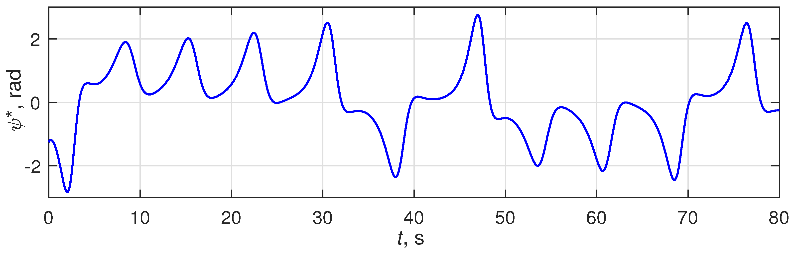
Figure 5.
Time history of Lorentz generator (10) output for , , , , and .
Figure 5.
Time history of Lorentz generator (10) output for , , , , and .

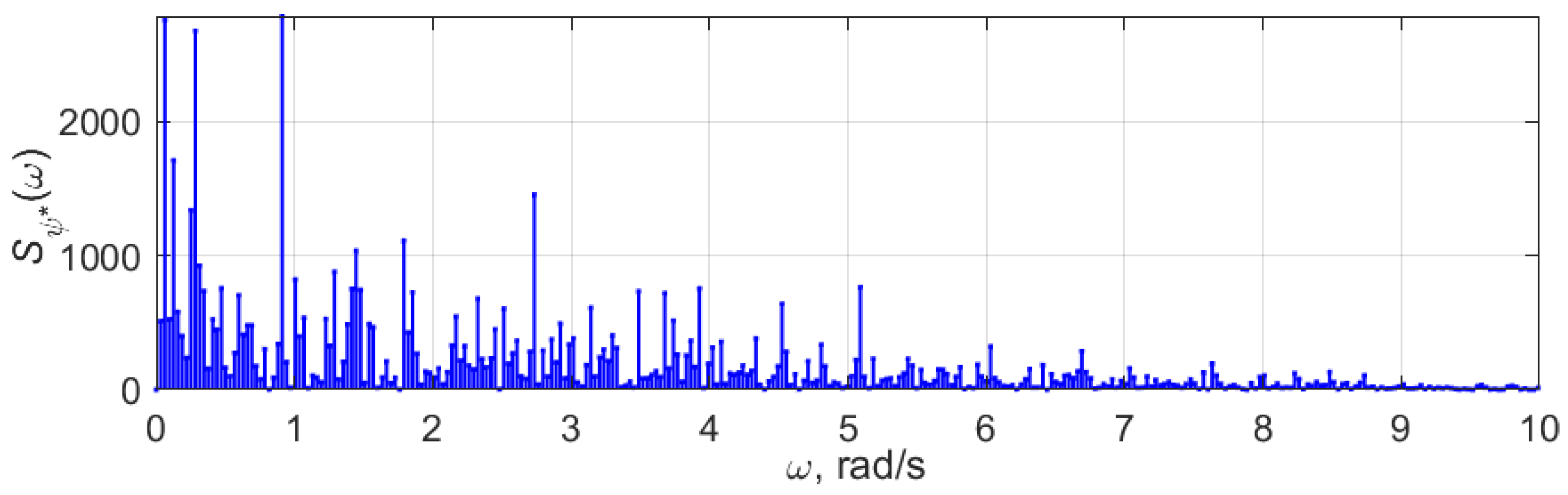
Figure 6.
Spectrogram of Lorentz generator (10) output for and .
Figure 6.
Spectrogram of Lorentz generator (10) output for and .

Figure 7.
Transients of for cases of free phase shift , , and as Lorentz generator (10) output.
Figure 7.
Transients of for cases of free phase shift , , and as Lorentz generator (10) output.

Figure 8.
Time histories of for cases of free phase shift , , and as Lorentz generator (10) output.
Figure 8.
Time histories of for cases of free phase shift , , and as Lorentz generator (10) output.

Figure 9.
Time histories of phase shift for cases of free phase shift , , and as Lorentz generator (10) output.
Figure 9.
Time histories of phase shift for cases of free phase shift , , and as Lorentz generator (10) output.

Figure 10.
Time histories of for and as Lorentz generator (10) output.
Figure 10.
Time histories of for and as Lorentz generator (10) output.

Figure 11.
Platform horisontal coordinate time histories for the cases of: -control absence, (upper plot), (middle plot) and as Lorentz generator (10) output (lower plot).
Figure 11.
Platform horisontal coordinate time histories for the cases of: -control absence, (upper plot), (middle plot) and as Lorentz generator (10) output (lower plot).


Figure 12.
Platform pitch angle time histories for the cases of: -control absence (upper plot), (middle plot), and as Lorentz generator (10) output (lower plot).
Figure 12.
Platform pitch angle time histories for the cases of: -control absence (upper plot), (middle plot), and as Lorentz generator (10) output (lower plot).


Figure 13.
Spectogramms of platform pitch angle for and as Lorentz generator (10) output.
Figure 13.
Spectogramms of platform pitch angle for and as Lorentz generator (10) output.

Figure 14.
Normalized autocorrelation function of platform pitch angle for and as Lorentz generator (10) output.
Figure 14.
Normalized autocorrelation function of platform pitch angle for and as Lorentz generator (10) output.

Figure 15.
Trajectories of point #1 on the vertical plane for the cases of: -control absence, (upper plot), (middle plot), and as a Lorentz generator (10) (lower plot). Red traces indicate maximums.
Figure 15.
Trajectories of point #1 on the vertical plane for the cases of: -control absence, (upper plot), (middle plot), and as a Lorentz generator (10) (lower plot). Red traces indicate maximums.


Publisher’s Note: MDPI stays neutral with regard to jurisdictional claims in published maps and institutional affiliations. |
© 2022 by the authors. Licensee MDPI, Basel, Switzerland. This article is an open access article distributed under the terms and conditions of the Creative Commons Attribution (CC BY) license (https://creativecommons.org/licenses/by/4.0/).
Share and Cite
MDPI and ACS Style
Andrievsky, B.; Zaitceva, I. Symmetrical Control Law for Chaotization of Platform Vibrations. Symmetry 2022, 14, 2460. https://0-doi-org.brum.beds.ac.uk/10.3390/sym14112460
AMA Style
Andrievsky B, Zaitceva I. Symmetrical Control Law for Chaotization of Platform Vibrations. Symmetry. 2022; 14(11):2460. https://0-doi-org.brum.beds.ac.uk/10.3390/sym14112460
Chicago/Turabian StyleAndrievsky, Boris, and Iuliia Zaitceva. 2022. "Symmetrical Control Law for Chaotization of Platform Vibrations" Symmetry 14, no. 11: 2460. https://0-doi-org.brum.beds.ac.uk/10.3390/sym14112460
Note that from the first issue of 2016, this journal uses article numbers instead of page numbers. See further details here.