Article

Mineralogical and Leaching Characteristics of Altered Ilmenite Beach Placer Sands

by
Munyadziwa Mercy Ramakokovhu
1,*,
Peter Apata Olubambi
2,
Richard Kady Kadiambuji Mbaya
1,
Tajudeen Mojisola
2 and
Moipone Linda Teffo
1
1
Institute for NanoEngineering Research, Department of Chemical, Metallurgical and Materials Engineering, Tshwane University of Technology, Pretoria 0001, South Africa
2
Centre for NanoEngineering and Tribocorrosion, School of Mining, Metallurgy and Chemical Engineering, University of Johannesburg, Johannesburg 2000, South Africa
*
Author to whom correspondence should be addressed.
Submission received: 7 July 2020 / Revised: 31 July 2020 / Accepted: 7 August 2020 / Published: 17 November 2020
(This article belongs to the Section Mineral Processing and Extractive Metallurgy)

Abstract

:
In order to have a good understanding of the treatment process and improvement on the market value of ilmenite beach placer sands, knowledge of its mineral composition and phase distribution is fundamental. In this study, a combination of characterization techniques including high-resolution scanning electron microscopy (HR-SEM), high-resolution transmission electron (HR-TEM) microscope, and X-ray diffraction (XRD) techniques was used to understand the mineralogical characteristics of ilmenite beach placer sands obtained from Richards Bay, South Africa. The mineral phase constituents of the ilmenite beach placer sands were studied before pre-oxidation and additive leaching in a chloride environment. During observations using XRD and HR-SEM, the ilmenite beach placer sands exhibited signature rhombohedral crystal form and crescentic pits with evidence of alteration phases. The characterized pre-oxidized ilmenite showed the presence of a ferric oxide film deposit of the particles. The leaching characteristics of both raw and pre-oxidized ilmenite was studied in the presence of additives. The leaching efficiency of the pre-oxidized ilmenite in the presence of additives increased by 20% at atmospheric conditions. The characterized residues show the improved amenability of pre-oxidized leach in chloride media. The formation of new phases containing pseudo-rutile indicated crystallographic disintegration by the movement of atoms during dissolution. Some particles retained the crescentic pit and the subangular grain structure; however, the phase changes were observed at the grain boundaries and grain edges. The leached residue’s EDS results still indicated the presence of pseudo-rutile and some minor unreacted oxides such as SiO2, Al2O3, and other trace metals. The trace metals impurities present in the as-received ilmenite were reduced by 80% in the final residue after the leaching.

1. Introduction

Synthetic rutile production from ilmenite has gained momentum with increasing demand in pigment production, ceramics, coverings, and pharmaceutical applications [1,2]. With the scarcity of natural rutile, ilmenite and its alteration products have become a significant source of synthetic rutile and the titanium final product. Given the lucrative properties of titanium and titanium-based products, the rise in exploiting the heavy mineral sands is high. More than half of the global reserves of ilmenite are situated in both South Africa and Australia [3,4]. Ilmenite is mined from altered igneous rocks. These beach placer sands are extracted from the nearby dunes by dredging and gravity concentration methods. The recovery of these reserves requires a closer look at the structural orientation of each respective deposit. The complexity and variance of ilmenite phase distribution create processing challenges [5,6].
Several studies [7,8,9], have dealt extensively with the natural weathering process of ilmenite. However, its susceptibility to this process poses that Mg2+, Mn2+, and Fe3+ can replace a challenge for process design as a substitution of the principal phase constitution Fe2+ apart from forming a large variety of intergrowth with Iron titanium oxides. The presence of Cr, Al, Si, and Mn as impurities complicates the deposits’ characteristics even further and decreases the market value [10,11]. Many processes commercially used or proposed to upgrade ilmenite to synthetic rutile involve pyrometallurgy and hydrometallurgy and are generally expensive [12,13,14]. Over the years direct hydrometallurgical leach processes were found to be advantageous in processing abundant ilmenite ores and low energy consumption and producing sufficiently high-quality synthetic rutile [15].
The complexity in using hydrometallurgical processes to convert ilmenite economically to synthetic rutile lies in its mineralogical composition and properties [16]. In aqueous solution, the titanium trioxide ions are still bound together as single (TiO3)2− ions, moving independently through the solution, with iron ions, represented as Fe2+. When ilmenite crystals are subjected to acidic media, the ionic bonds are broken first because they are non-directional and allow the charged species to move freely [17]. Secondly, when salts dissolve into water, the ionic bonds are typically broken by the interaction with water, but the covalent bonds continue to hold. Fe2+ dissolves, and oxygen from titanium trioxide gets attracted to hydrogen ions. As a result of the dissolution challenges, research efforts have focused on adding additives to enhance the solubility of iron from the ilmenite compound [18]. Ilmenite reactivity in chloride media can be significantly enhanced by creating a reducing environment using metallic iron [19]. The inclusion of sulfate of divalent metal (Ca and Mg) as a catalyst has proved to increase the ilmenite leaching efficiency. The catalyst’s sulfate ions in solution lower the energy gap of the chemical reaction while decreasing the free acid content and fine generation in the spent solution, enhancing the leaching efficiency [20].
Chloride leaching processes have evolved and developed in techniques and strategies, but still face challenges in waste management, cost, and lengthy residence time [21]. This study seeks to determine the mineralogical structural changes of raw and pre-oxidized ilmenite during leaching, the formation of different structures, and the possible influence these structural changes have on the leaching characteristics of ilmenite. The focus will be directed on the characteristics of the deposit and the impact of changing mineralogy by pre-oxidation aid amenability of altered ilmenite beach placer sands to chloride additive leaching.

2. Materials and Methods

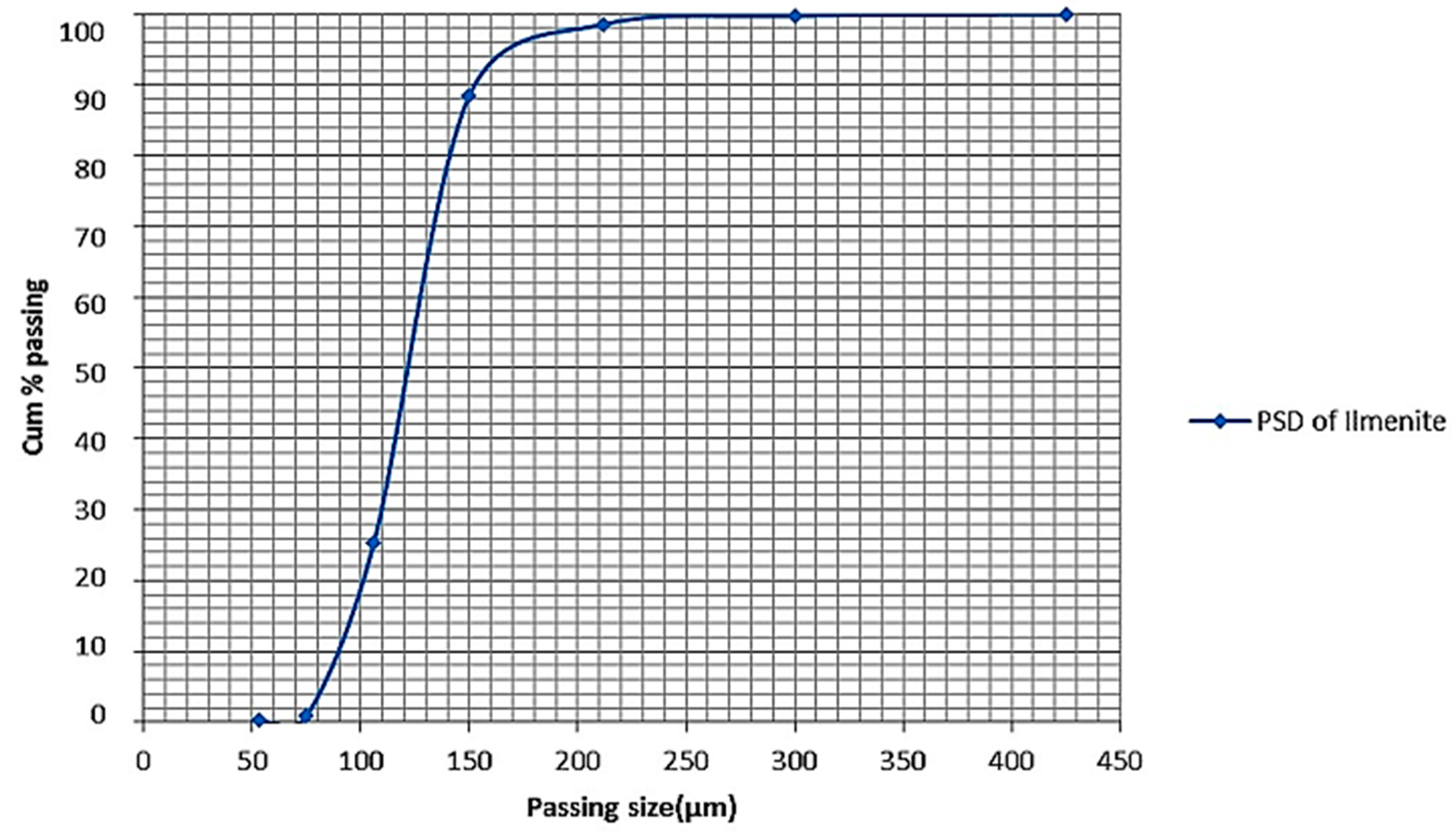
2.1. Mineralogical Studies on the Ilmenite Beach Placer Sands

The ilmenite samples used in this study were ilmenite beach placer sands collected from Richards Bay Minerals in South Africa. The particle size distribution of the sands was determined using the Malvern particle size analyzer and confirmed by the standard laboratory Tyler series sieves as both methods determine the cut size. The X-ray fluorescence spectrometry technique was used to determine the ilmenite sands’ chemical composition, while the phases within the sand were identified using the X-Ray diffractometer technique using the PANalytical Empyrean Powder X-ray diffraction. The morphologies and the backscattered electrons of the sand were observed using a Jeol HR-SEM (model JSM 7600F, JEOL, Akishima, Japan), and the elemental compositions were mapped using energy dispersive spectrometry (EDS) techniques.

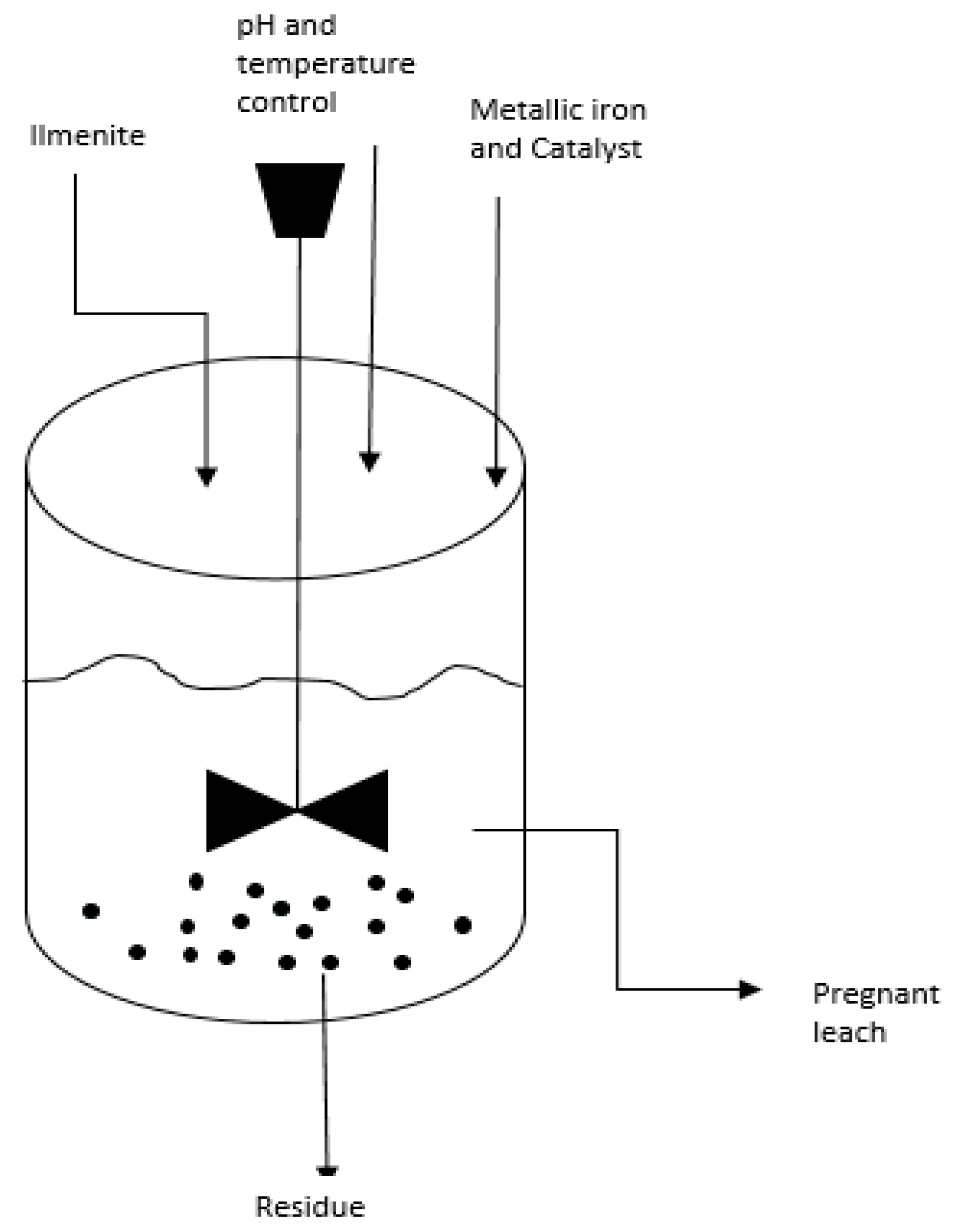
2.2. Pre-Oxidation and Leaching Studies

The ilmenite was pre-oxidized by heating the material to 817 °C in a muffle furnace in the presence of oxygen. The ramping furnace rate was 100 °C/h. The pre-oxidized ilmenite sands were air-cooled to room temperature. The PANalytical Empyrean powder X-ray diffraction determined the phase analyses, and the morphology of the pre-oxidized ilmenite was observed using a Jeol HR-SEM (high-resolution scanning microscope) (model JSM 7600F). The Jeol HR-TEM (high resolution-transmission microscope) was used to determine the crystallographic structure of the material.
Figure 1 shows a schematic overview of the leaching process. Ilmenite was leached using a 500 mL reactor placed on a heated plate. A mechanical stirrer with a maximum speed of 450 rpm was used to keep the slurry suspended during the experiment. De-ionized (DI) water was used to make up the slurry, and anhydrous hydrochloric acid was dosed to regulate the pH of the solution. The leaching was carried out at atmospheric pressure varying parameters such as temperature, acid concentration, agitation, solid to liquid ratio, and the residence time. The pH meter with a temperature gauge was used to measure both temperature and the pH. Magnesium sulfate was introduced at varying volumes and concentrations as a catalyst. Metallic iron was also introduced to the solution as a reducing agent. The pregnant leach solution was sampled intermittently at 30 min intervals for the duration of the leaching cycle. For statistical viability, the tests were repeated three times. Ammonium difluoride (NH4HF4) was used as an additive because of its ability to attack the glassy silica component that forms during leaching.
The leaching efficiency is calculated based on the amount of iron and impurities removed from ilmenite. The pregnant leach solution was characterized using ICP-OES (inductively coupled plasma-optical emission spectrometry). The residue was characterized using a Jeol HR-SEM (model JSM 7600F) and Jeol HR-TEM. Equation (1) shows the reaction involved during leaching.
FeTiO3 + 4HCl → FeCl2 + TiOCl2 + 2H2O

3. Results

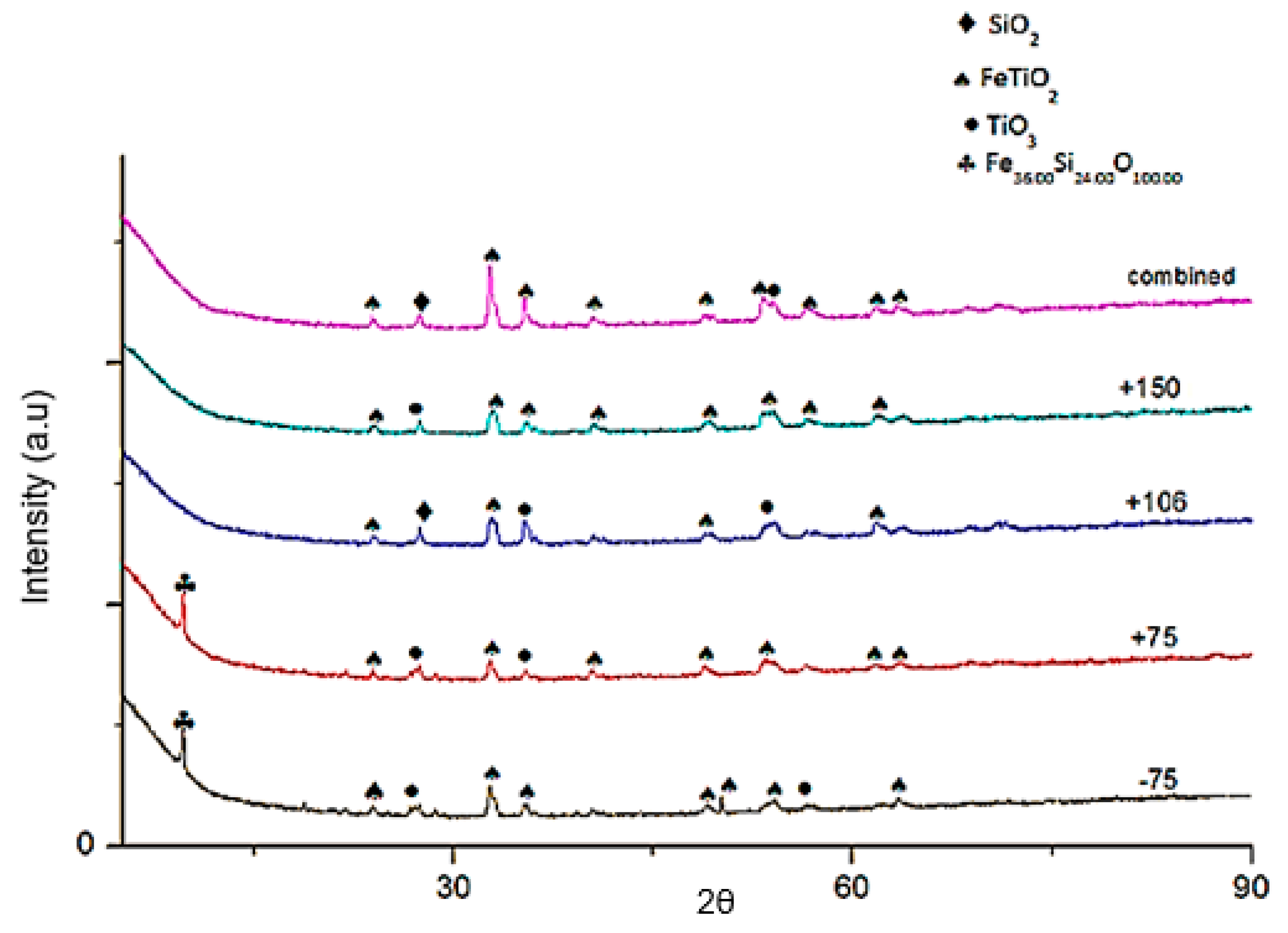
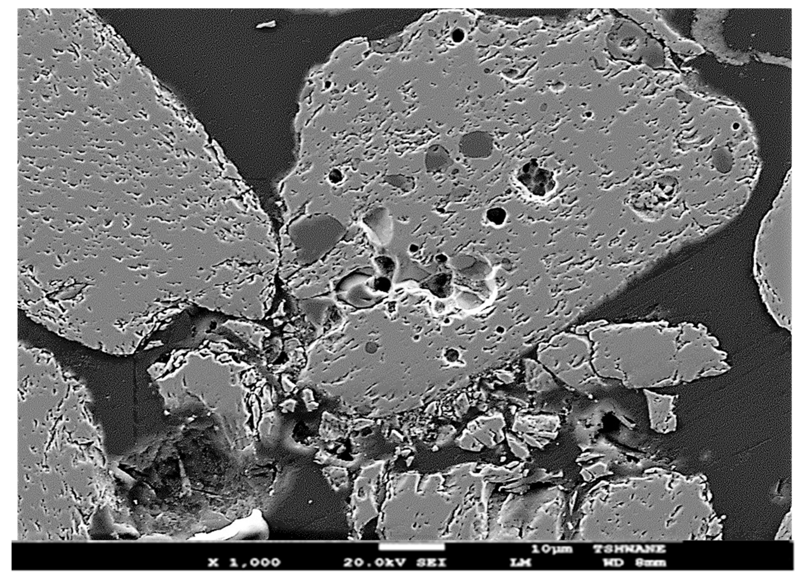
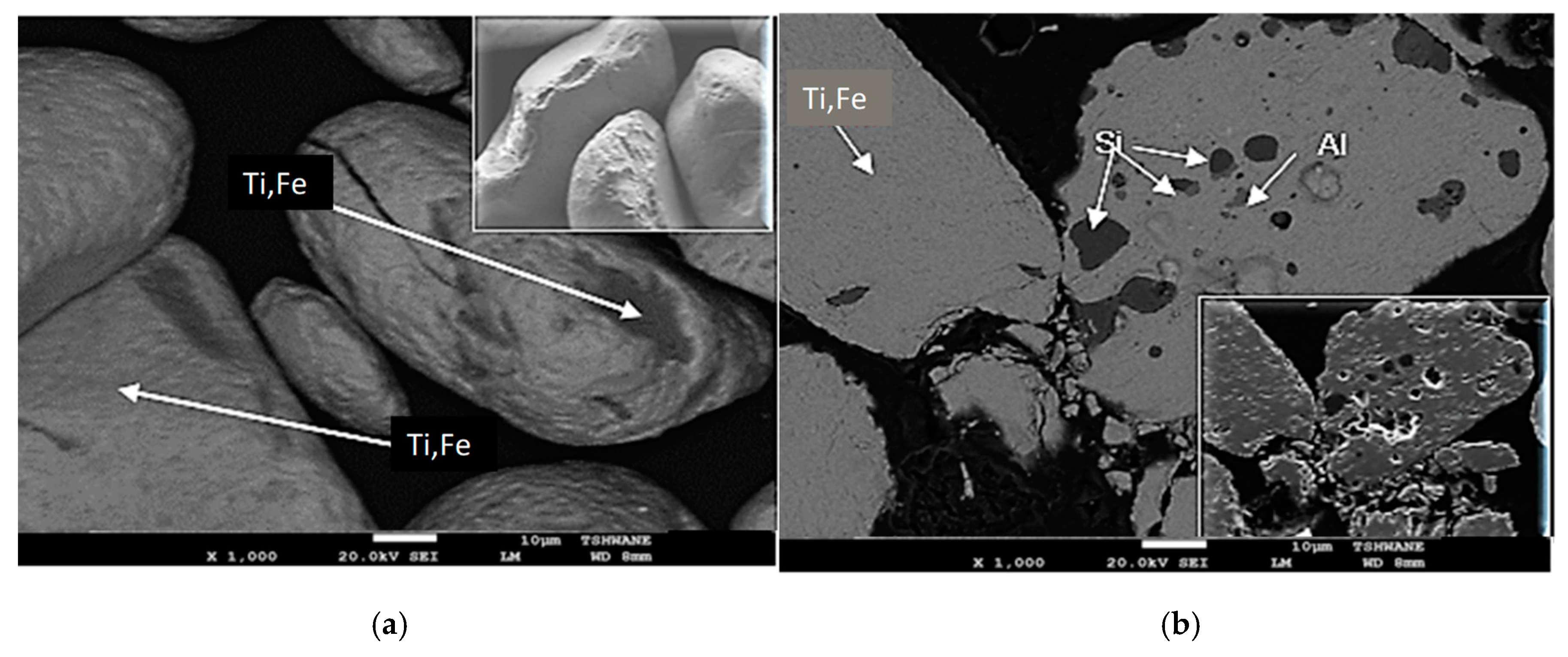
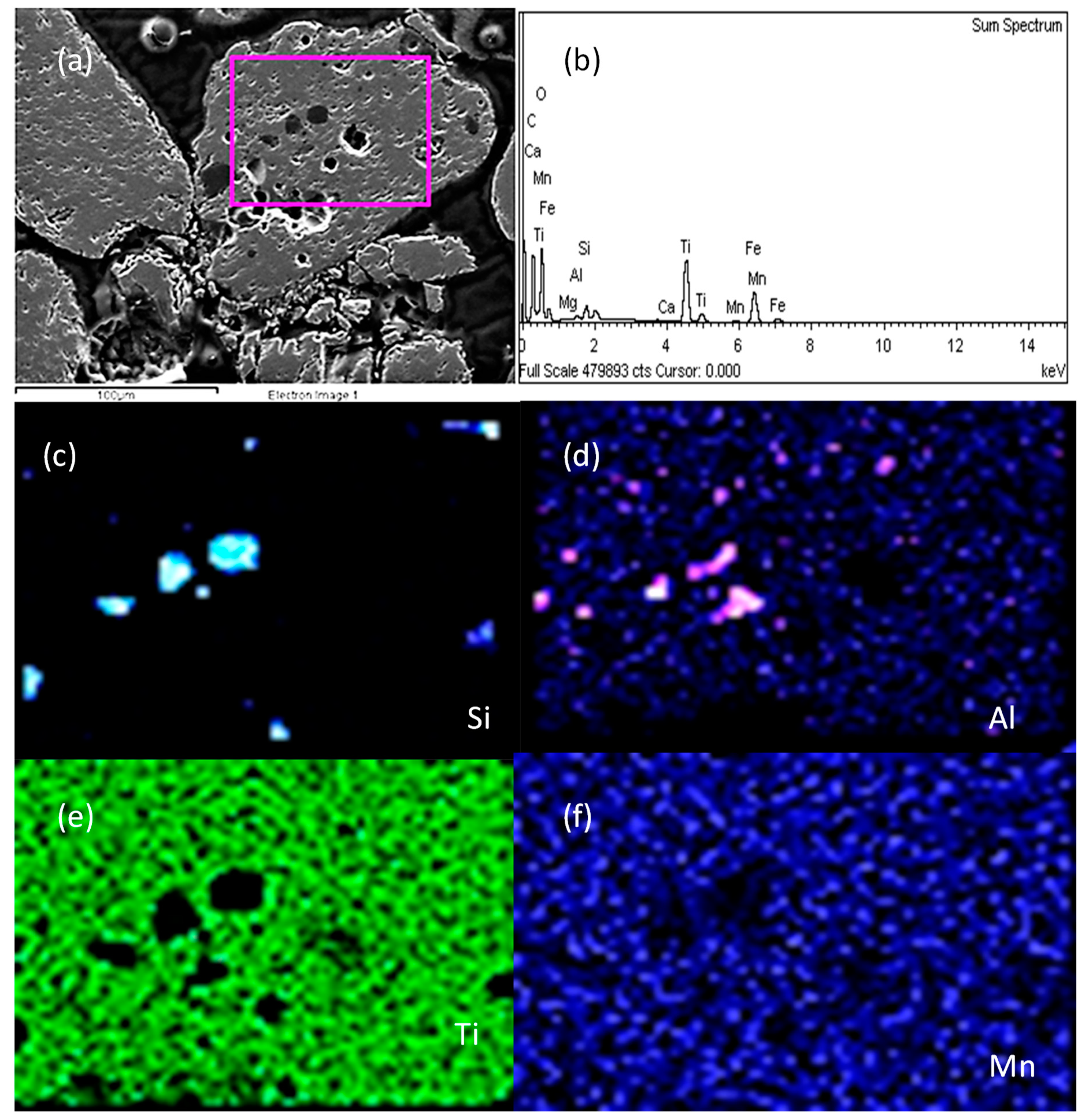
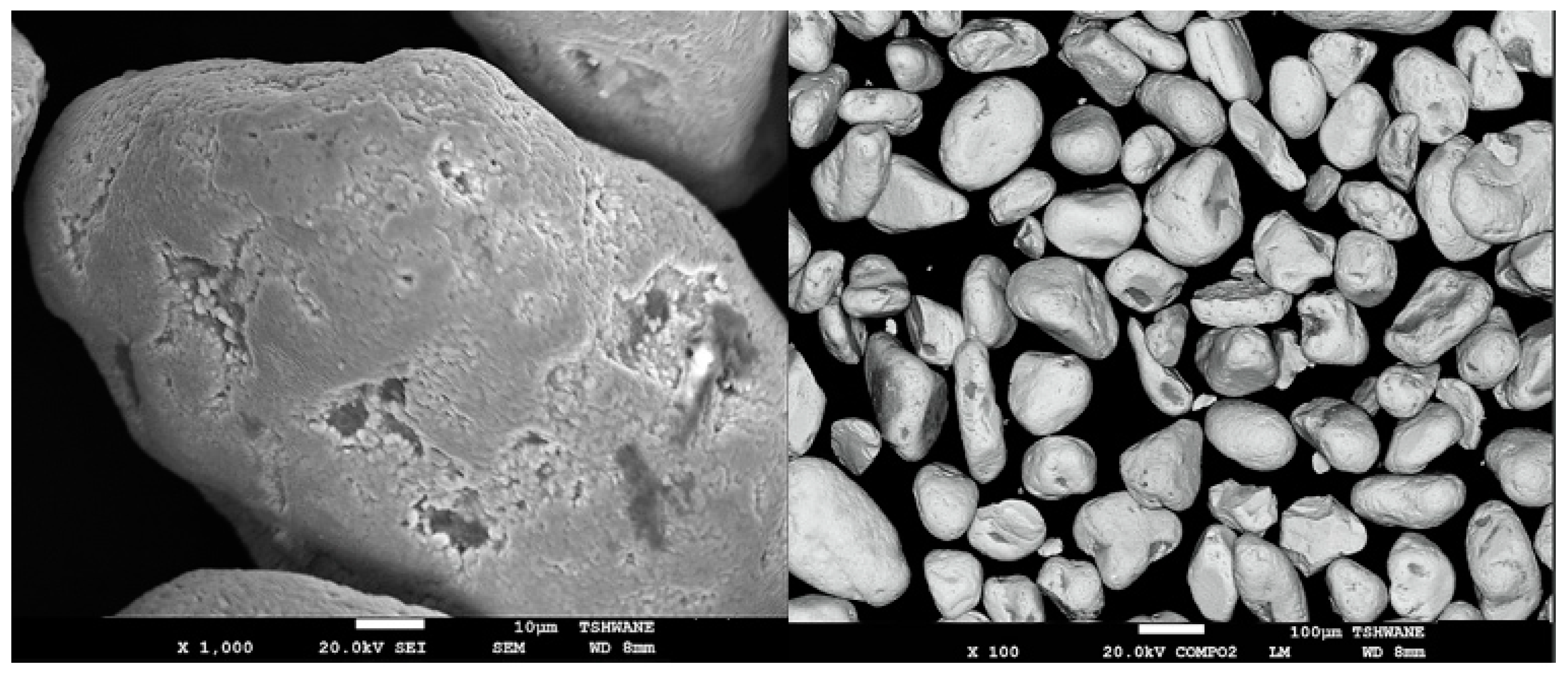
3.1. Mineralogy of As-Received Ilmenite

In Figure 2, the particle size distribution means that a particle size (d50) of 136 µm was observed. The diffraction patterns of each particle size range of the as-received ilmenite are shown in Figure 3. The background peaks and peak position in the diffractogram showed ilmenite (FeTiO3), rutile (TiO2), and silica (SiO2) as the major mineral phases in both finer and coarse fractions. The lower-sized fractions (−106, −75-micrometer size) showed the (Fe2)SiO4 iron-silicate phase. The silicate phase in ilmenite deposits hosts impurity inclusions as it is the major gangue mineral phase. In line with XRD results, the chemical composition of as-received ilmenite material shown in Table 1 comprises 48.23% Fe2O3 and 42.93% TiO2. The results showed that SiO2 (2.94%), Al2O3 (1.71%), and MnO (1.11%) represent the gangue minerals; however, the crystalline structure of MnO and Al2O3 could not be detected by XRD as they were below the detection limit. Other associated gangue materials were observed as traces <1%. The presence of Al2O3 and SiO2 further suggested that there was an alteration of the ilmenite mineralogical structure. The alumina and silica enrichment facilitates impurity inclusions within the structure post-deposition.
The particle size and shape identification by high-resolution scanning electron microscope (HR-SEM) analysis is shown in Figure 4. At lower magnification (×100), the observed embedded micrographs show an elongated shape feature of ilmenite. Ilmenite crystalline structure is rhombohedral as per the observation; the particle size ranges from 50–200 µm. The tiny grooves (pits) and veins observed at higher magnification (×500, ×1000) suggest the migration of atoms from the crystalline structural lattice further confirms mineralogical alteration of the material. The abrasion and cracks observed are a result of the particle to particle impact and collision during transportation from the sea bed.
The cross-sectioned particle micrograph (Figure 5) shows the pits protruding through the minerals structure. The suggested atoms migration is evident as there are spots that show darker colors than the original structure. The migration leaves pits allowing impurity atoms to deposit on the empty sites. The backscattering electron micrographs (Figure 6) shows the different minerals’ phases within the ilmenite structure. Using the elemental mapping technique (Figure 7), the ilmenite phase is concentrated on the grey colored phase, silica (dark black) and alumina (light grey) are inter-deposited within the ilmenite grain on the pits.
Similar to the XRD and XRF results, the EDS elemental mapping micrographs (Figure 7) show the presence of impurity inclusion within the ilmenite structure, confirming the assertion of the material mineralogical orientation has been altered. According to Buick and Dunlop [22], ilmenites have corundum structures with oxygen anions in the hexagonal tightly packed lattice and Fe and Ti cations occupying two-thirds of the interstices. Typically the ilmenite alterations and deposits in the Richards Bay area have chemical compositions containing a wide range of elements (Ca2+, Mn2+, Fe3+), which can substitute the Fe2+ in the lattice structure [23]. The manganese substitutions in the weathering transformation phase (pseudorutile) occur in the range of 0.6–1%, which is similar to what is observed in the chemical composition of this material [24].
Changes in the mineralogical orientation of deposits create new dynamics in the structure’s amenability to leaching. The impurity amounts shown in Figure 6 and Figure 7 determine the weathering and process’s extent, which affects the quality and recoverability of ilmenite.
The TEM micrographs (Figure 8) of the as-received ilmenite indicated the ilmenite deposit’s polycrystalline nature. The latticed-spacing of the ilmenite shown in Figure 8 is 0.3740 nm. The mineral is in plate form with spiky and cracked morphology. The cracks observed penetrate deeper in the particle to the 250 nm size range. Due to the visible cracks, the particle has been altered, alteration of individual particles occurs along the rims and cracks as iron is readily displaced from the lattice.

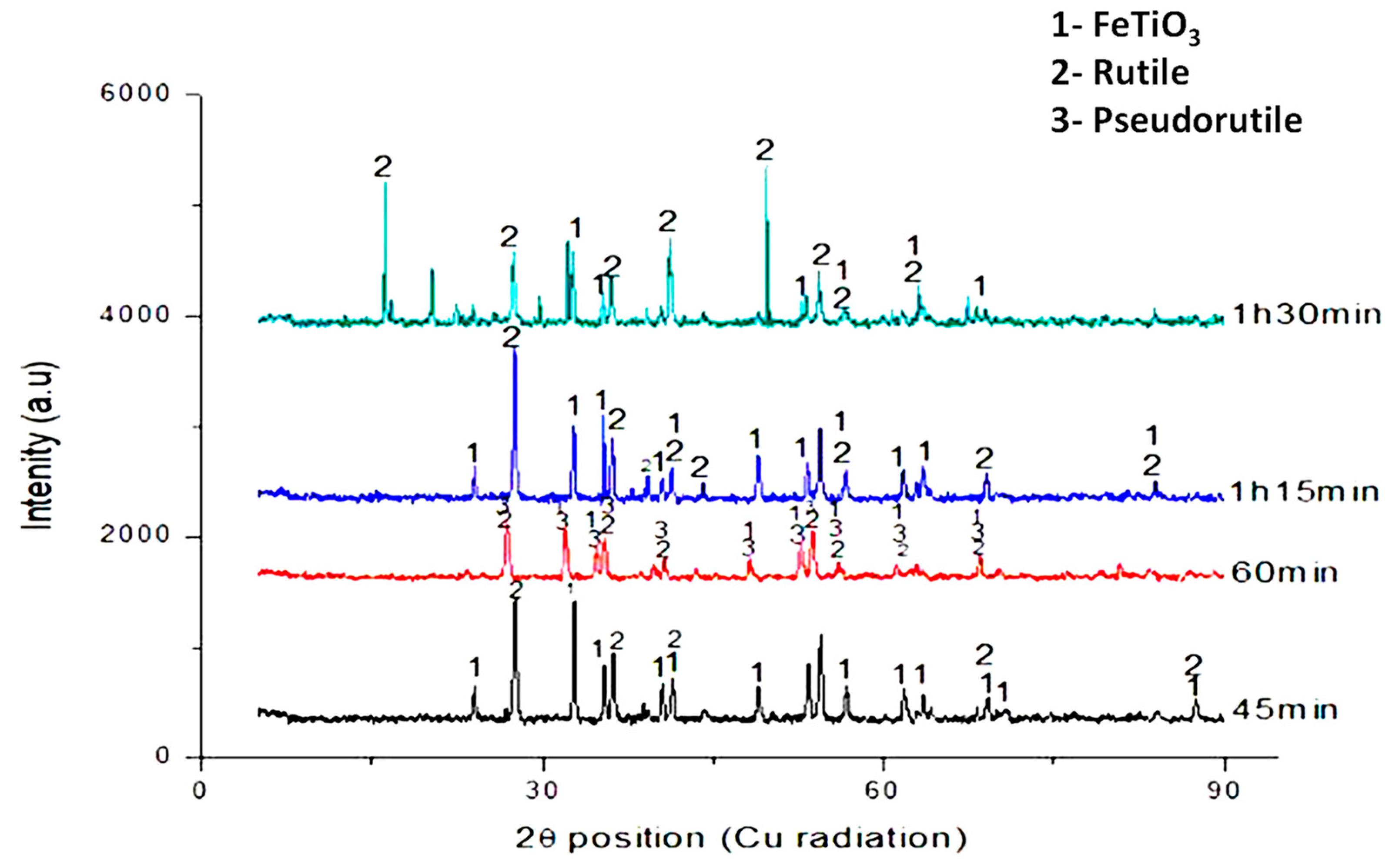
3.2. Pre-Oxidized Ilmenite Mineralogy

The pre-oxidized ilmenite micrographs (Figure 9) show the ferric oxide phase’s presence emanating from the oxidation process. The gradual formation of the Fe2O3·2TiO2 intermediate phase (Equation (2)) can be observed at a temperature of 800 °C. The relatively smooth and homogeneous surface morphology with eccentric pits (Figure 9) allows the Fe2O3 content of the intermediate phase to further break down to ferric oxide, which is amenable to leaching. McConville and Lee [25] reported the breaking down of the pseudo rutile at temperatures between 600 °C and 900 °C to form hematite and rutile due to diffusion during prolonged heating promoting the breakdown from the primary ilmenite particles changing the surface morphology of the particles creating a porous structure on the surfaces. The formation of the porous structure would favor the diffusion of the lixiviant during leaching.
2FeTiO3 + ½O2 → Fe2O3·2TiO2

3.3. Leaching Characteristics

It is well established that the additives and reductants significantly affect the leaching efficiency of ilmenite from the electrochemical results. The response of as-received and pre-oxidized ilmenite to additive and reductive leaching was studied in a series of test works performed at atmospheric conditions. Figure 10 shows the leaching efficiency of ilmenite over time. It can be observed that when only metallic iron is added to the solution, the leaching efficiency of ilmenite is the lowest for both as-received and pre-oxidized samples. The NH4HF4 substantially increased the as-received ilmenite leaching efficiency. The active HF component etches the passivation layer formed during leaching allowing interface reaction to continue increasing the dissolution rate of ilmenite. It can be noted that the pre-oxidized ilmenite response to leaching supersedes that of the as-received ilmenite at atmospheric conditions. In the same Figure 10, the leaching efficiency of the pre-oxidized ilmenite for all additives increased compared to the as-received ilmenite. The porous structure attained during the pre-oxidation step favors the solid–liquid interaction process during the ilmenite leaching process. The micropores enhance the mass transfer rate of leaching reagents through the ferric oxide layer promoting the dissolution reaction. Therefore, this validates the assertion by Liu and Xiang [26] that the exposure of hematite through pre-oxidation promotes dissolution and untreated ilmenite has low reactivity to HCl. Mahamoud et al. [19] reported that the addition of metallic iron reduces the dissolved Fe3+ to Fe2+ and significantly improves the iron dissolution rate.

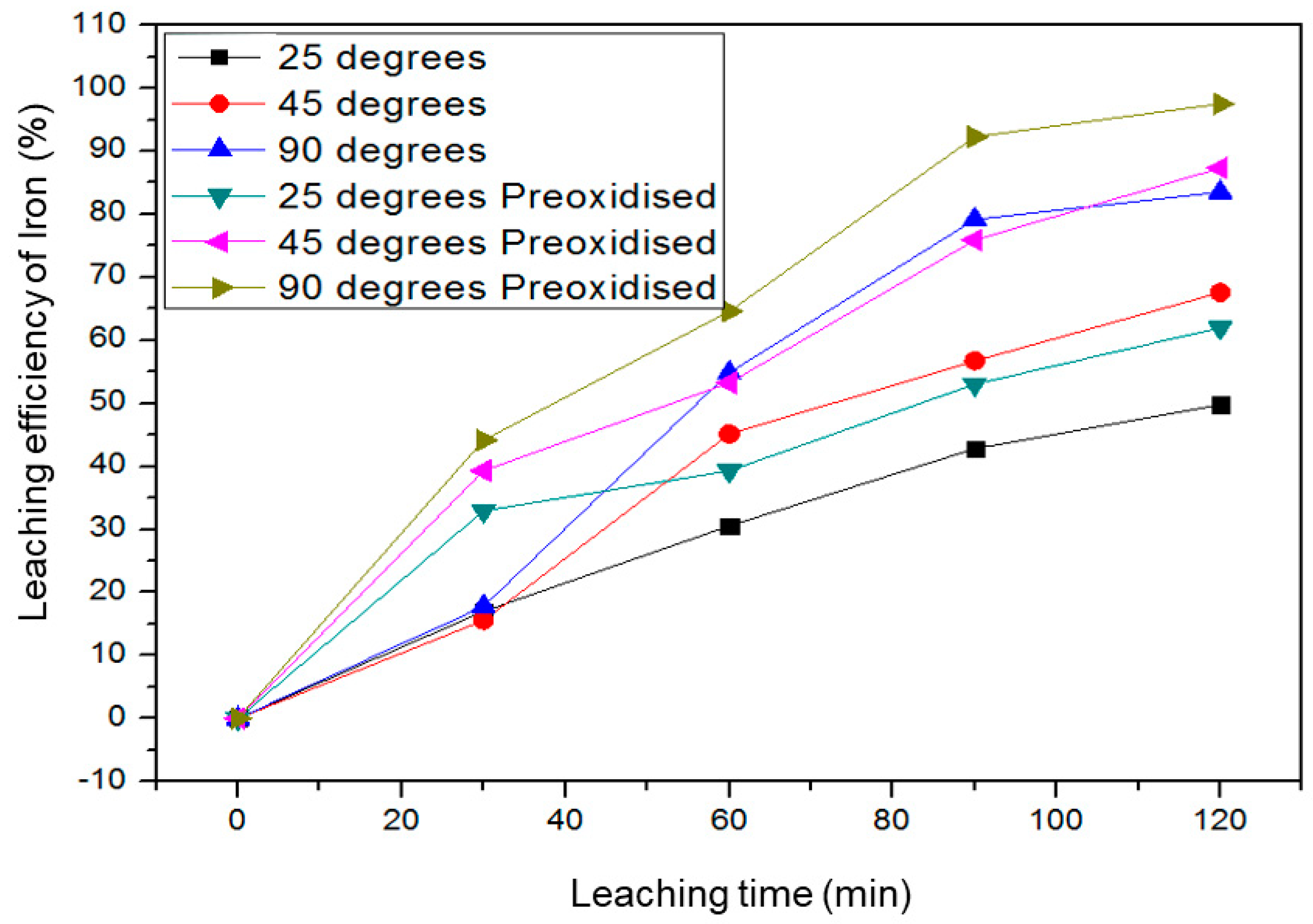
3.3.1. Effect of Temperature on the Leaching Efficiency of Ilmenite

The effect of temperature on ilmenite’s leaching efficiency was investigated at 9.6 M, HCL in the presence of NH4HF4, and metallic iron. From the results presented in Figure 11, it can be noted that the increase in temperature increased the leaching efficiency of ilmenite. Moreover, the pre-oxidized sample had the highest leaching efficiency at all temperatures. The operational temperature was kept at 90 °C to avoid the formation of HF and HCL vapors at higher temperatures.

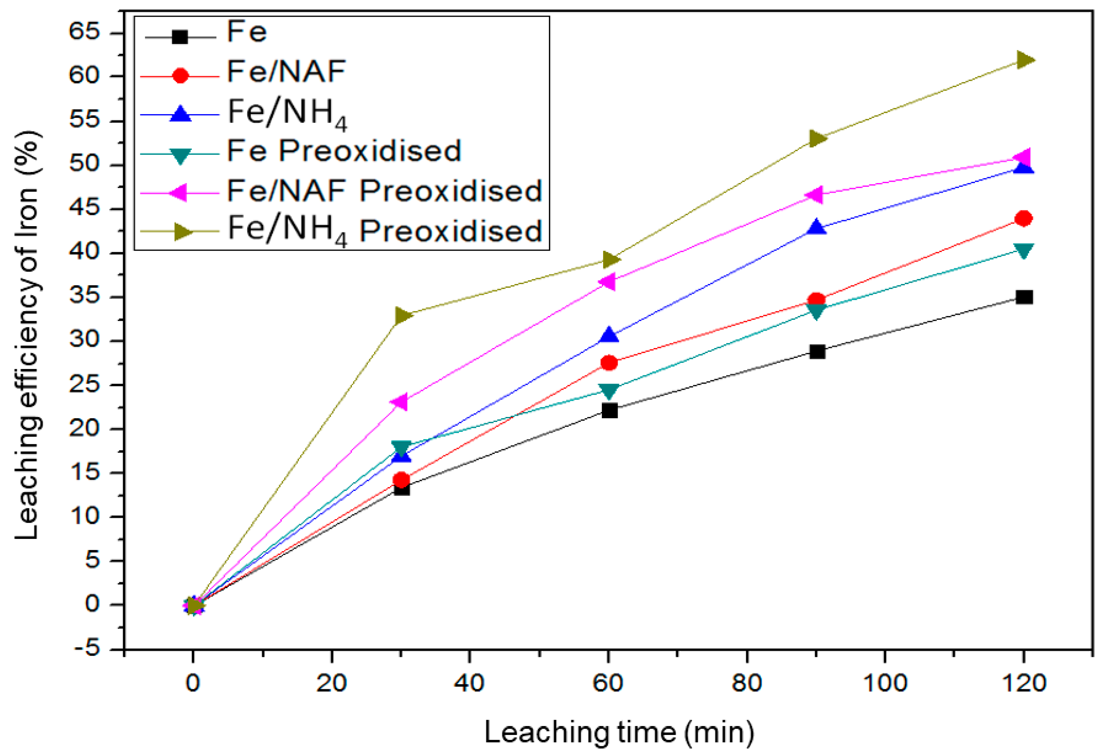
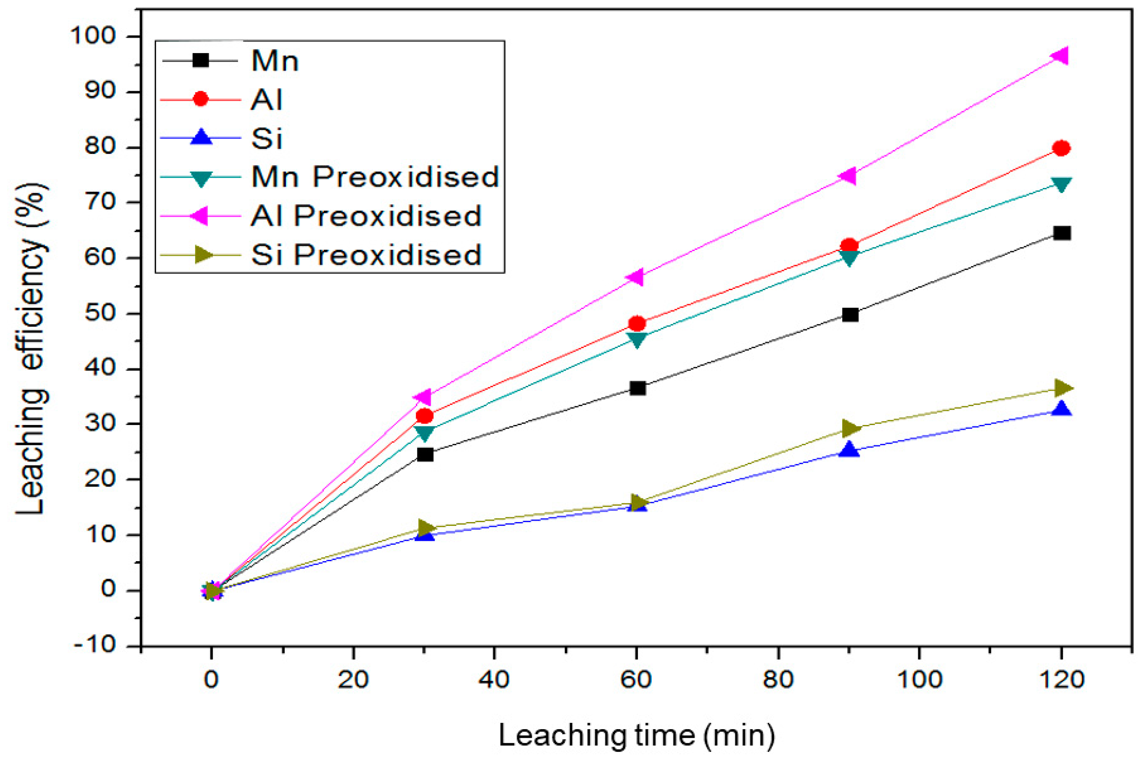
3.3.2. The Behavior of Impurities during Leaching

Manganese, alumina, and silica form part of the crystalline structure of ilmenite coexisting as intra and inter impurities. In application, these impurities affect the quality of the final product. While maintaining the same leaching conditions, the behavior of the impurities was observed. Figure 12 presents the leaching characteristics of impurities associated with ilmenite. It can be observed that alumina had the highest leaching efficiency, which can be attributed to alumina’s deposition characteristics. When observing the ilmenite crystal structure (Figure 5, Figure 6 and Figure 7), the alumina deposited on the intra part of the crystallographic structure, making it easy to be leached out.
In the case of manganese, it was optimally leached to lower levels. The manganese grains are embedded within the ilmenite crystalline structure during alteration hence limiting complete extraction. Silica has the lowest extraction rate as it has larger grains embedded within the structure.

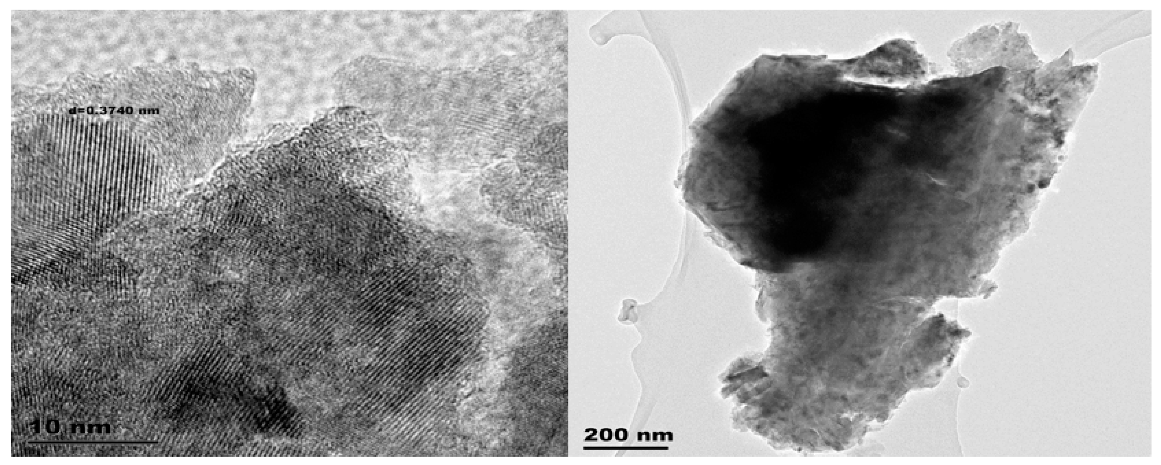
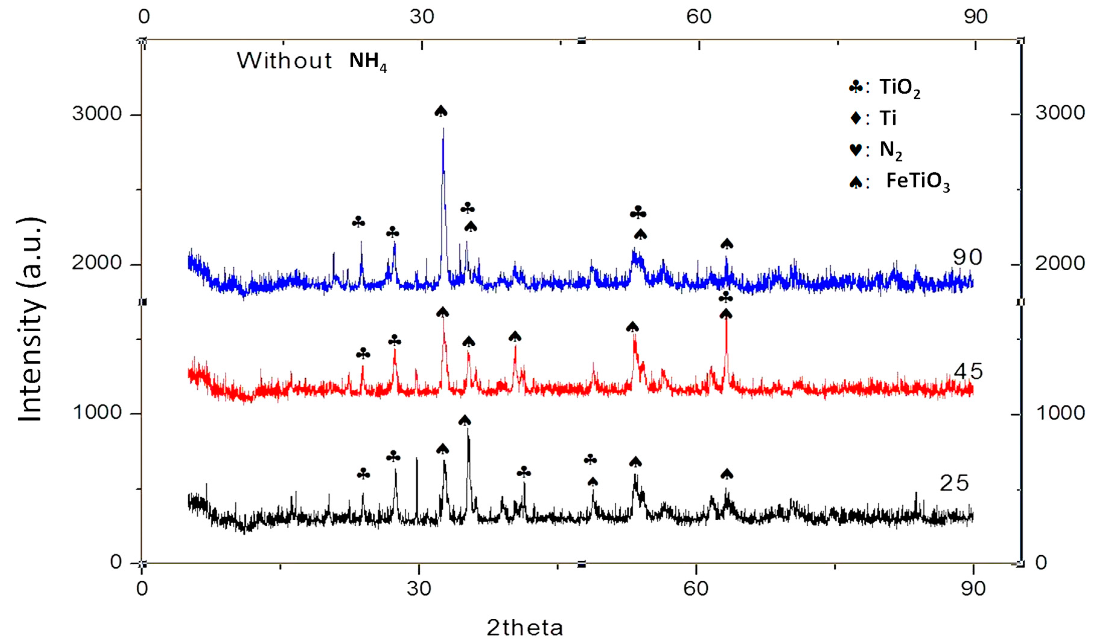
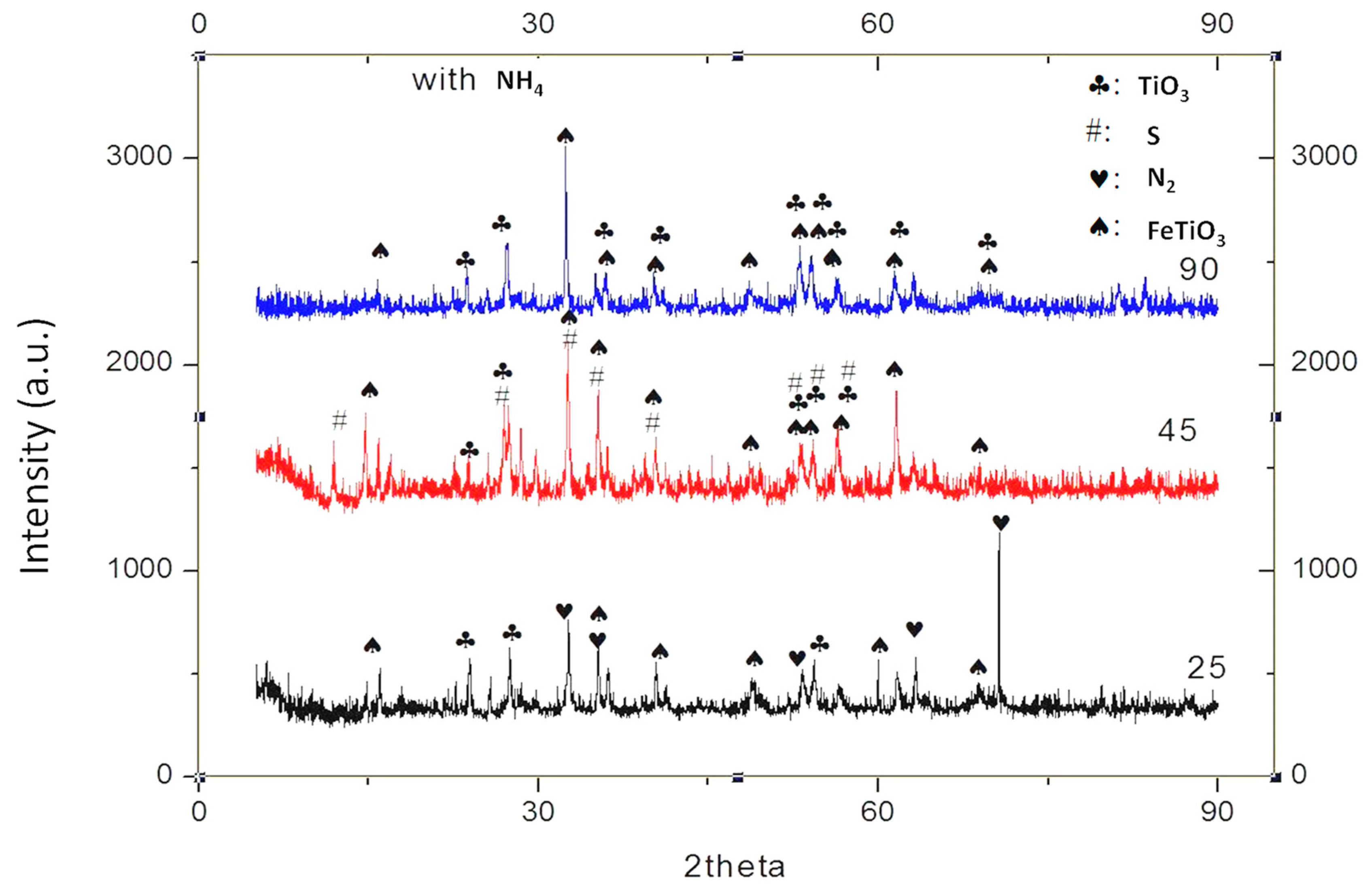
3.3.3. Mineral Phase Constitution of Ilmenite Leaching Residues

Figure 13 shows the mineral phase constitution of the as-received ilmenite leached at the optimum condition at different time intervals from 45 min to 1 h 30 min, at 90 °C. Compared with Figure 3 (as-received ilmenite XRD diffractogram), the x-ray diffractograms of the residue samples were studied after each leaching time interval. New diffraction peaks appeared after a 45-min leach indicating surfacing rutile peaks as ilmenite dissolution occurs. Intermediate phases transformed into rutile; however, most unreacted ilmenite peak intensity is visible in the material.
Figure 14 shows the phase constitution of the pre-oxidized ilmenite during leaching at different temperatures. It can be observed that ilmenite peaked at high intensity at lower temperatures (25 and 45 °C). It can be attributed to the low iron dissolution rates at lower temperatures. At 90 °C, there are high-intensity peaks of the rutile phase, confirming that iron dissolution increases with an increase in temperature. When comparing the pre-oxidized ilmenite with the as-received material, the rutile peaks are more intense in the pre-oxidized sample than the as-received material. The rutile phase dominance in pre-oxidized material is attributed to the ferric oxide layer, which leaches faster, leaving the rutile phase exposed.
Figure 15 shows the phase pattern of the pre-oxidized ilmenite leached in the presence of ammonium additives. It can be observed that at 25 °C there is a higher peak ilmenite peak intensity with few picks of TiO2 and nitrogen. The peak intensity for ilmenite reduces as temperature increases; there are phase changes as the overlap between sulfur, TiO2, and ilmenite observed when leaching was conducted at 45 °C. At 90 °C, a precise observation of the dominant TiO2 phase constitution confirms the assertion that the pre-oxidized ilmenite leached successfully in the presence of ammonium. When contrasting with the XRD pattern for the leached as-received ilmenite, pre-oxidized leached without additives, the additive leach shows a significant increase in the TiO2 as temperature increases. To have a fully comprehensive understanding of how the crystallographic orientation was affected by leaching, a further mineralogical investigation was required.

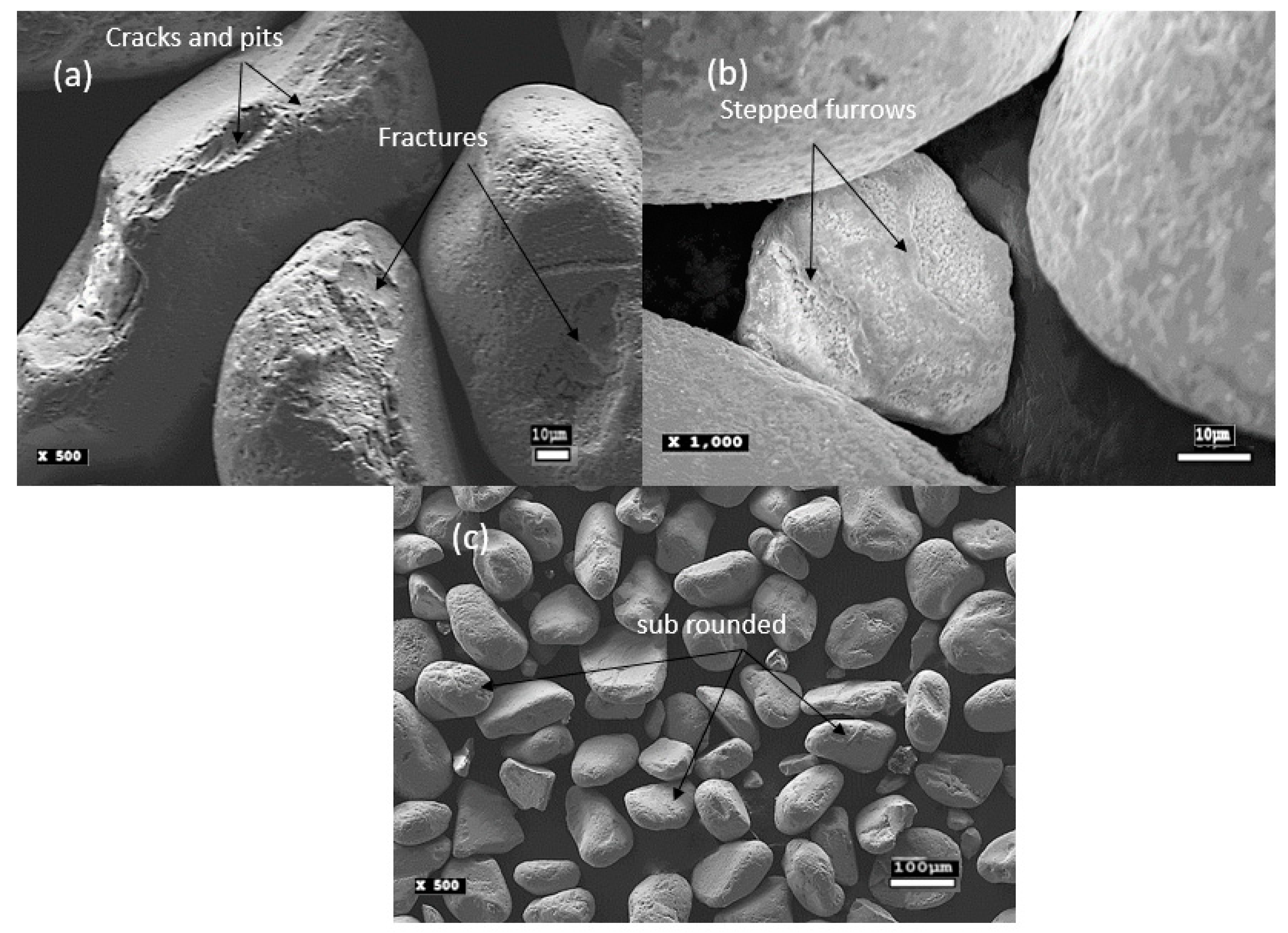
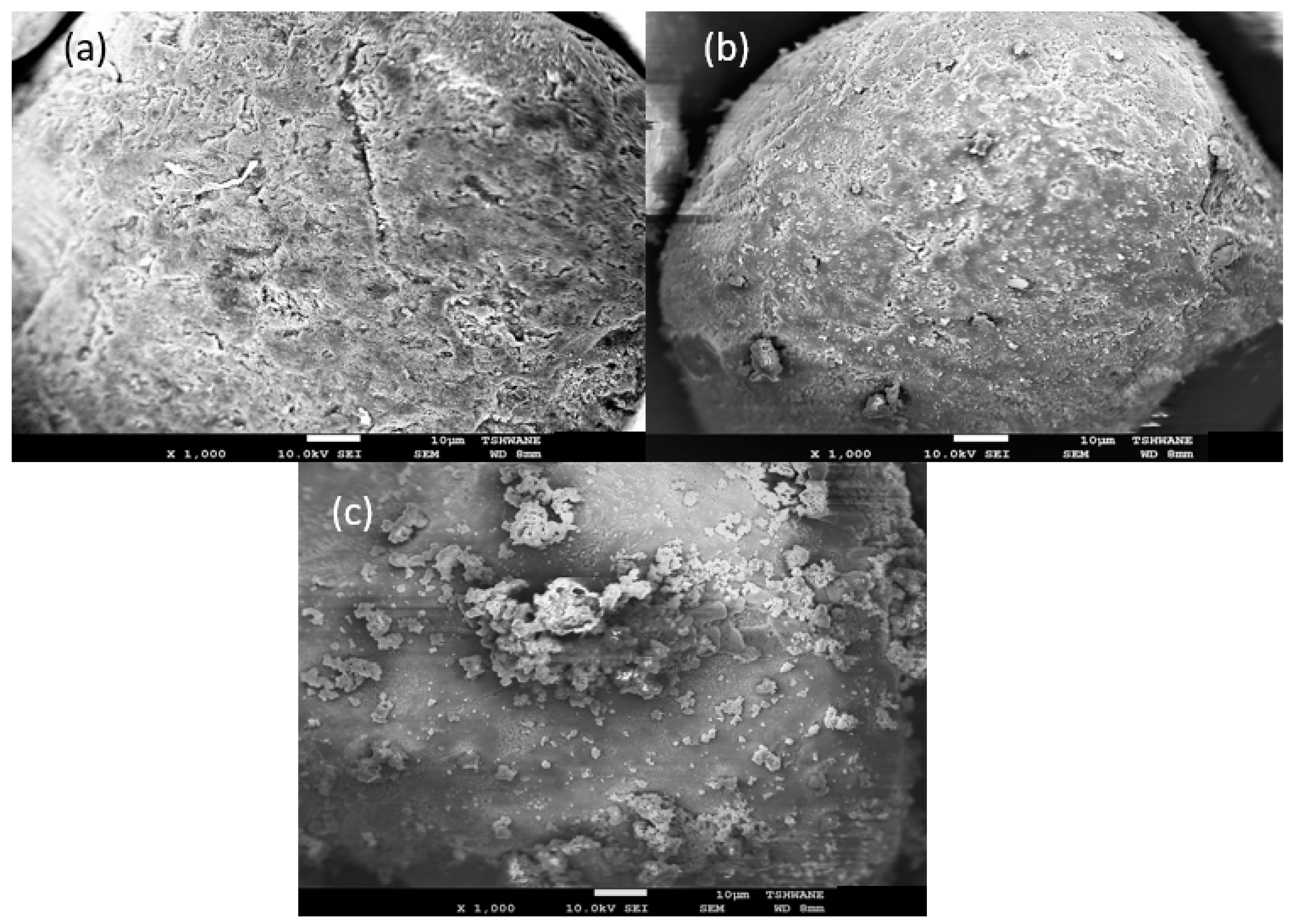
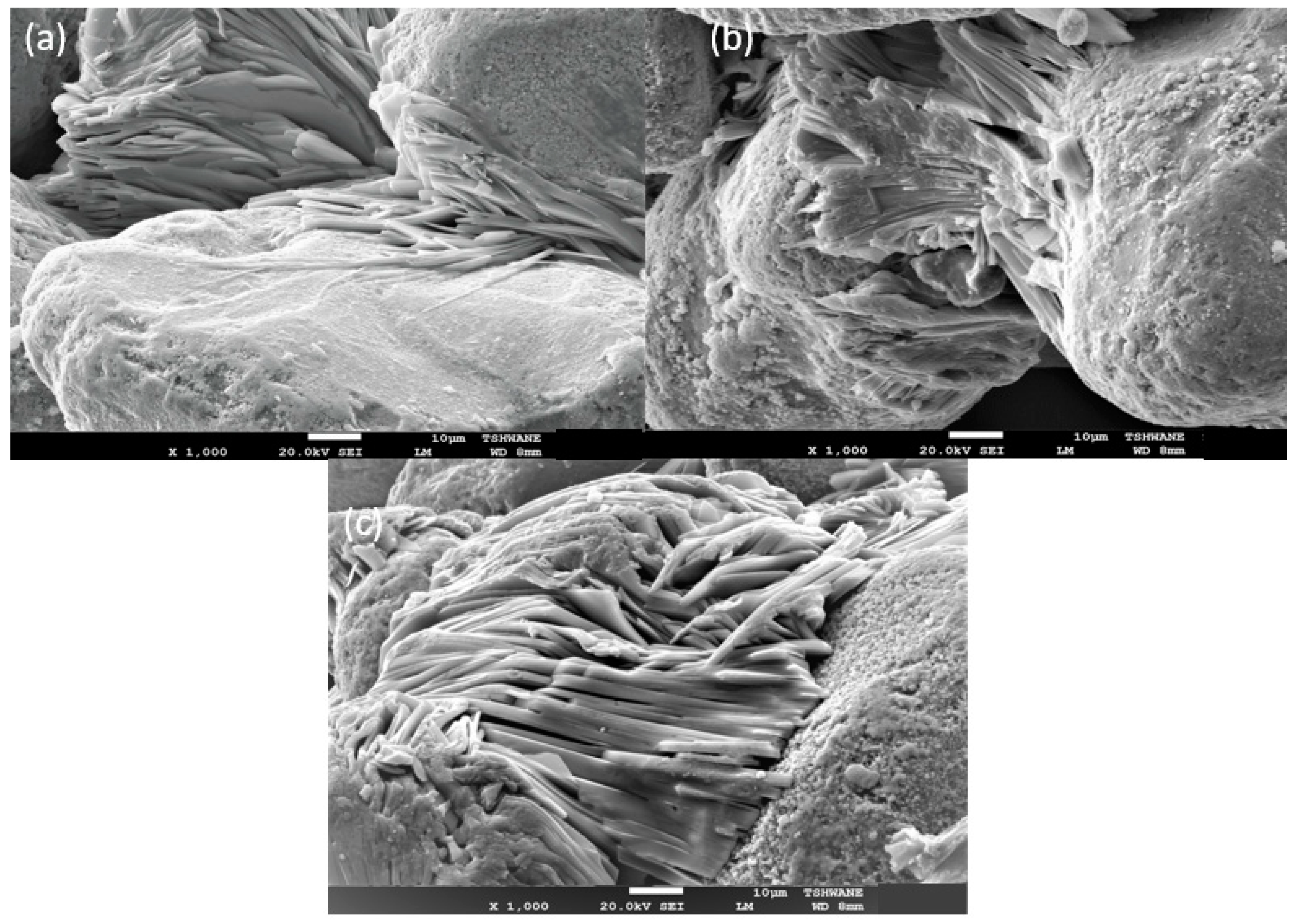
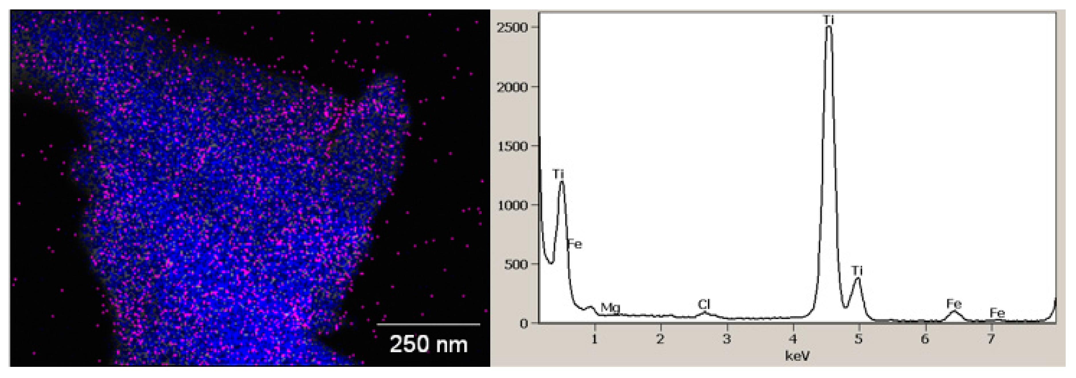
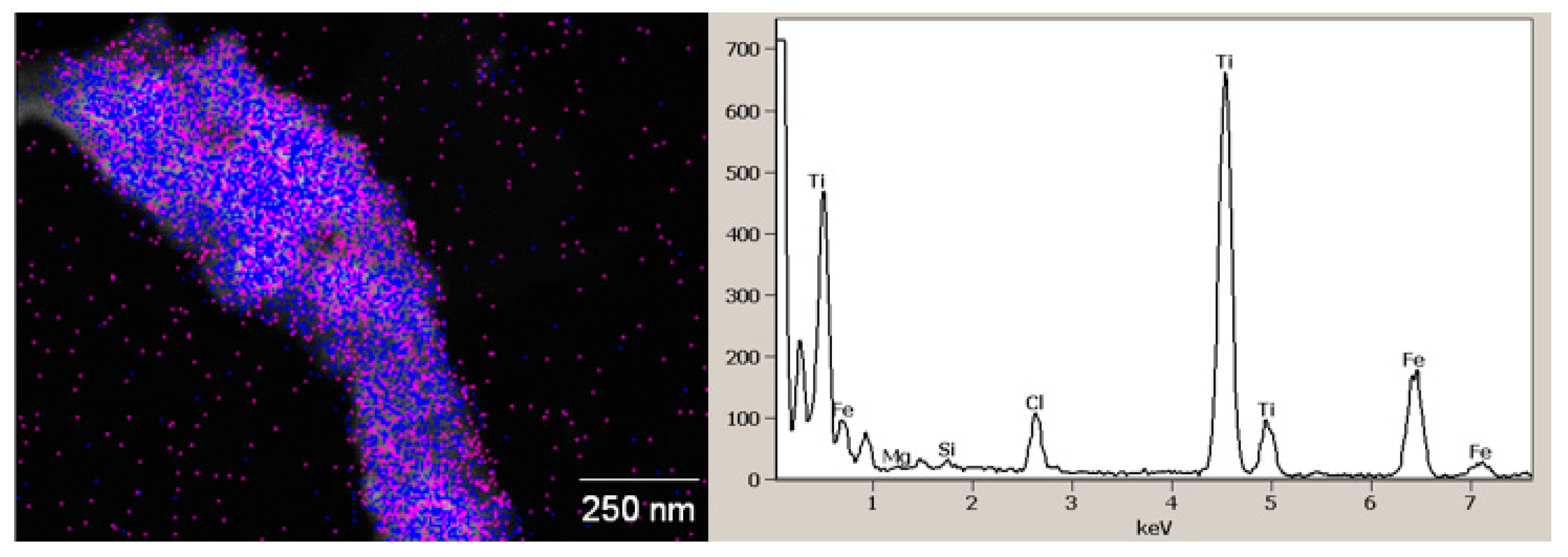
3.3.4. Mineralogical Characterization of Leaching Residue Using SEM

Therefore, the residue was analyzed using a high-resolution scanning electron microscope (SEM) to determine the surface morphology and mineralogical orientation of the residue at each interval for both standard and additive leaching. Figure 16 shows the electron micrographs of the optimally leached ilmenite at different temperature intervals. The morphology of the residues after leaching at 25 °C observed (Figure 16a) showed no deposition or surface film build up during the leaching test, indicating that there was minimal dissolution that occurred. When observing Figure 16b,c, precipitation or a surface film can be observed, with a thicker layer observed on Figure 16c, it confirms that there is indeed a higher dissolution rate that occurs at high temperatures. The film on the particles shows distinct character, but there is no crystal disorientation; however, the fine particle cluster formation or deposition observed as the mineral build-up is targeted explicitly at the rough edges of the mineral surface. The surface layer is also thicker at the grooves, attributed to deposition and polymerization of titanium on the ridges during the leaching of iron from the crystal lattice.
Figure 17 shows the electron micrographs of the pre-oxidized ilmenite leaching residues in the presence of reducing agent and ammonium additives. When observing the microstructures, it can be deduced that the ilmenite crystallographic structure was broken down during leaching. When comparing the micrographs in Figure 16 and Figure 17, it is evident that the dissolution kinetics of the iron were altered by the presence of a reducing agent, in this case, metallic iron. Sasikumar, Srikanth [27] also observed that iron alters the iron titania bond’s chemical composition, making it unstable and amenable to dissolution by hydrochloric acid.
Figure 17a,b the particles show partial dissolution under microscopy at similar magnification and lower temperatures. It can be observed that the particle disintegration started at the edges of the particle, which is the area where the ferric oxide layer was deposited. The removal of iron and other base metal from the lattice also creates gaps in the crystal lattice resulting in line grooves. At higher temperatures (Figure 17c), the particle shows evident disintegration of the crystalline structure because of the high dissolution rate of iron and associated impurities.
In comparison with the leached as-received ilmenite sample in Figure 16, it can be deduced that the pre-oxidation enhanced the leaching efficiency of ilmenite. In Figure 16, there is no evident sign of particle breakdown, as in contrast to the evident disintegration of the euclic bond shown in Figure 17. To further understand the nature of the crystallographic disorientation, a closer look at the single leached particle through TEM was instigated.
Figure 18 shows the TEM leached residue’s TEM micrographs for the pre-oxidized ilmenite leached in the presence of reductant and ammonium salt. The micrograph (Figure 18) observed showed the amorphous and partly polycrystalline nature of the residue. As shown in Figure 18, the latticed-spacing difference is due to the mineral phase transformation to titania. The crystallographic disintegration of ilmenite particles is due to the migration of iron and impurity mineral atoms to the solution. As per the observation, it can be deduced that the amorphous part in the ilmenite crystal represents the disintegrated area shown in Figure 17.
The polycrystalline area represents the unreacted part of the ilmenite particle. It can be observed that the amorphous area is predominantly on the edges of the crystal, which confirms the assertion that during pre-oxidation, the ferric oxide, which is amenable to leaching, is moved to the periphery of the ilmenite particle. Therefore, during leaching, the edges are disintegrated to form the amorphous phase.
Figure 19 shows the micrograph of the leach residue crystals. It can be observed that the various ilmenite residue crystals are in the plate-like structure. The crystal orientation exhibits a similar orientation of the flat plate-like structure, which has a spiky orientation. The flat plate structure is attributed to the rhombohedral nature of the ilmenite crystals. It can be deduced from the origin of the deposit where during transportation of the ilmenite minerals, the collision of the particles caused cracks hence the spiky orientation.
The leaching residue at different leaching time intervals was mapped using TEM, and the micrographs and EDS results are presented in Figure 20, Figure 21 and Figure 22. The observed micrograph (Figure 20), after 30 min of leaching, shows the presence of all the impurities in the crystalline structure.
In Figure 21, after 20 min, the manganese peaks were eliminated with low iron intensity peaks and chloride peaks from the leach solution. In comparison with the mapping in Figure 20, the leach residue decreases iron peaks as the leaching retention time increases. The final residues (Figure 22) confirm the assertion that there is a decrease in the intensity of the iron peaks; similarly, there is also the elimination of manganese, aluminum in the crystalline structure. The magnesium and silica impurity peaks are very low in intensity, suggesting that the ICP-OES results confirm a significant reduction in their concentration.

4. Conclusions

The pre-oxidation of the altered ilmenite beach placer sands provides a unique opportunity to transform the sands’ mineralogical characteristics. By comparing the initial impurity characteristics of the as-received ilmenite beach sands, it is evident that the pre-oxidation increased the amenability of the sands to chloride leach. The shredded and disarranged surface orientation of the ilmenite increased the iron dissolution rate. The ilmenite mineral phase was converted to pseudo-rutile at intermediate time intervals, as the retention time increases the final mineral phase transformation to rutile. During the dissolution of iron, there is a change in d-spacing, the polycrystalline structure to amorphous.

Author Contributions

Conceptualization and methodology, M.M.R., T.M., and P.A.O.; formal analysis, R.K.K.M.; investigation, M.M.R.; data curation, M.L.T.; writing—original draft preparation, M.M.R. and P.A.O.; writing—review and editing, R.K.K.M. All authors have read and agreed to the published version of the manuscript.

Funding

This research was funded by the National Research Foundation (NRF) Thuthuka grant.

Acknowledgments

The authors gratefully acknowledge the financial support received from the National Research Foundation (NRF) and the Tshwane University of Technology, South Africa.

Conflicts of Interest

The authors declare no conflict of interest. The funders had no role in the design of the study; in the collection, analyses, or interpretation of data; in the writing of the manuscript, or in the decision to publish the results.

References

  1. Gázquez, M.J.; Bolívar, J.P.; Garcia-Tenorio, R.; Vaca, F. A review of the production cycle of titanium dioxide pigment. Mater. Sci. Appl. 2014, 5, 441–458. [Google Scholar] [CrossRef] [Green Version]
  2. El-Sherbiny, S.; Morsy, F.; Samir, M.; Fouad, O.A. Synthesis, characterization and application of TiO2 nanopowders as special paper coating pigment. Appl. Nanosci. 2014, 4, 305–313. [Google Scholar] [CrossRef] [Green Version]
  3. Amer, A. Alkaline pressure leaching of mechanically activated Rosetta ilmenite concentrate. Hydrometallurgy 2002, 67, 125–133. [Google Scholar] [CrossRef]
  4. Moila, A.; Chetty, D.; Ndlovu, S. The application of process mineralogy on a tailings sample from a beach placer deposit containing rare earth elements. J. South Afr. Inst. Min. Metall. 2017, 117, 615–621. [Google Scholar] [CrossRef] [Green Version]
  5. Ahmad, S.; Rhamdhani, M.A.; Pownceby, M.I.; Bruckard, W.J. Analysis of sulfidation routes for processing weathered ilmenite concentrates containing impurities. In 6th International Symposium on High-Temperature Metallurgical Processing; Springer: Berlin/Heidelberg, Germany, 2015. [Google Scholar]
  6. Pownceby, M.I.; Sparrow, G.J.; Fisher-White, M.J. Mineralogical characterisation of Eucla Basin ilmenite concentrates–First results from a new global resource. Miner. Eng. 2008, 21, 587–597. [Google Scholar] [CrossRef]
  7. Bruckard, W.J.; Pownceby, M.I.; Smith, L.K.; Sparrow, G.J. Review of processing conditions for Murray Basin ilmenite concentrates. Miner. Process. Extr. Metall. 2015, 124, 47–63. [Google Scholar] [CrossRef]
  8. Panigrahi, M.; Shibata, E.; Iizuka, A.; Nakamura, T. Production of Fe–Ti alloy from mixed ilmenite and titanium dioxide by direct electrochemical reduction in molten calcium chloride. Electrochim. Acta 2013, 93, 143–151. [Google Scholar] [CrossRef]
  9. Pownceby, M.; Fisher-White, M. Chemical variability in chrome spinel grains from magnetically fractionated ilmenite concentrates: Implications for processing. Miner. Process. Extr. Metall. 2006, 115, 213–223. [Google Scholar] [CrossRef]
  10. Wang, Y.; Yuan, Z.; Matsuura, H.; Tsukihashi, F. Reduction extraction kinetics of titania and iron from an ilmenite by H2–Ar gas mixtures. ISIJ Int. 2009, 49, 164–170. [Google Scholar] [CrossRef] [Green Version]
  11. Grey, I.; MacRae, C.; Silvester, E.; Susini, J. Behaviour of impurity elements during the weathering of Ilmenite. Miner. Mag. 2005, 69, 437–446. [Google Scholar] [CrossRef]
  12. Wei, L.; Hu, H.; Chen, Q.; Tan, J. Effects of mechanical activation on the HCl leaching behavior of plagioclase, ilmenite and their mixtures. Hydrometallurgy 2009, 99, 39–44. [Google Scholar] [CrossRef]
  13. Wu, F.; Li, X.; Wang, Z.; Xu, C.; He, H.; Qi, A.; Yin, X.; Guo, H. Preparation of high-value TiO2 nanowires by leaching of hydrolyzed titania residue from natural ilmenite. Hydrometallurgy 2013, 140, 82–88. [Google Scholar] [CrossRef]
  14. Zhang, L.; Hu, H.; Liao, Z.; Chen, Q.; Tan, J. Hydrochloric acid leaching behavior of different treated Panxi ilmenite concentrations. Hydrometallurgy 2011, 107, 40–47. [Google Scholar] [CrossRef]
  15. Vasquez, R.; Molina, A. Leaching of ilmenite and pre-oxidized ilmenite in hydrochloric acid to obtain high grade titanium dioxide. In Proceedings of the 17th International Metallurgical & Materials Conference Proceedings: METAL, Hradec and Moravici, Czech Republic, 13–15 May 2008. [Google Scholar]
  16. El-Hazek, N.; Lasheen, T.; El-Sheikh, R.; Zaki, S.A. Hydrometallurgical criteria for TiO2 leaching from Rosetta ilmenite by hydrochloric acid. Hydrometallurgy 2007, 87, 45–50. [Google Scholar] [CrossRef]
  17. Welham, N.; Llewellyn, D. Mechanical enhancement of the dissolution of ilmenite. Miner. Eng. 1998, 11, 827–841. [Google Scholar] [CrossRef]
  18. Li, C.; Liang, B.; Guo, L.-H.; Wu, Z.-B. Effect of mechanical activation on the dissolution of Panzhihua ilmenite. Miner. Eng. 2006, 19, 1430–1438. [Google Scholar] [CrossRef]
  19. Mahmoud, M.; Afifi, A.; Ibrahim, I. Reductive leaching of ilmenite ore in hydrochloric acid for preparation of synthetic rutile. Hydrometallurgy 2004, 73, 99–109. [Google Scholar] [CrossRef]
  20. Gireesh, V.; Vinod, V.; Nair, S.K.; Ninan, G. Catalytic leaching of ilmenite using hydrochloric acid: A kinetic approach. Int. J. Miner. Process. 2015, 134, 36–40. [Google Scholar] [CrossRef]
  21. Mukherjee, A.; Raichur, A.M.; Modak, J.M. Dissolution studies on TiO2 with organics. Chemosphere 2005, 61, 585–588. [Google Scholar] [CrossRef]
  22. Buick, R.; Dunlop, J. Evaporitic sediments of early Archaean age from the Warrawoona Group, North Pole, Western Australia. Sedimentology 1990, 37, 247–277. [Google Scholar] [CrossRef]
  23. Deysel, K. Leucoxene study: A mineral liberation analysis (MLA) investigation. In Proceedings of the 6th International Heavy Minerals Conference ‘Back to Basics’, The Southern African Institute of Mining and Metallurgy, Richards Bay, South Africa, 9–14 September 2007. [Google Scholar]
  24. Das, G.; Pranolo, Y.; Zhu, Z.; Cheng, C. Leaching of ilmenite ores by acidic chloride solutions. Hydrometallurgy 2013, 133, 94–99. [Google Scholar] [CrossRef]
  25. McConville, C.J.; Lee, W.E. Microstructural development on firing illite and smectite clays compared with that in kaolinite. J. Am. Ceram. Soc. 2005, 88, 2267–2276. [Google Scholar] [CrossRef]
  26. Liu, S.-L.; Xiang, J.-Y. The effects of thermal pretreatment on leaching of yunnan ilmenite with hydrochloric acid. Metall. Mater. Trans. B 2016, 47, 1334–1339. [Google Scholar] [CrossRef]
  27. Sasikumar, C.; Srikanth, S.; Mukhopadhyay, N.; Mehrotra, S. Energetics of mechanical activation–Application to ilmenite. Miner. Eng. 2009, 22, 572–574. [Google Scholar] [CrossRef]
Figure 1. Leaching process schematic overview.
Minerals 10 01022 g001
Figure 2. Particle size distribution curve.
Minerals 10 01022 g002
Figure 3. Diffractometer patterns of as-received ilmenite samples at different particle size (µm) ranges with black (−75 µm) red (+75 µm) blue (+106 µm) green (+150 µm) pink (before sieving).
Minerals 10 01022 g003
Figure 4. As-received ilmenite micrographs under different magnification. (a) Cracks, (b) Furrows, (c) Particle shape.
Minerals 10 01022 g004
Figure 5. Cross-sectional image of the as-received ilmenite particle.
Minerals 10 01022 g005
Figure 6. Backscattered electron micrograph of as-received ilmenite (a) charged particle (b) cross-sectioned particle.
Minerals 10 01022 g006
Figure 7. EDS elemental mapping micrographs of the as-received ilmenite particle. (a) Cross sectioned area, (b) EDX spectra, (c) Silica, (d) Aluminum, (e) Titanium, (f) Managanese.
Minerals 10 01022 g007
Figure 8. TEM micrograph of an as-received ilmenite particle.
Minerals 10 01022 g008
Figure 9. Pre-oxidized ilmenite backscattered electron micrographs at different magnification.
Minerals 10 01022 g009
Figure 10. The leaching characteristics of as-received and pre-oxidized ilmenite in the presence of reductants and additives at atmospheric conditions.
Minerals 10 01022 g010
Figure 11. The effect of temperature on the leaching efficiency of as-received and pre-oxidized ilmenite, when using NH4HF4 and Fe as additives in chloride media.
Minerals 10 01022 g011
Figure 12. The characteristic behavior of impurities during leaching.
Minerals 10 01022 g012
Figure 13. XRD mineral phase constitution during leaching of the as-received ilmenite, Black (45 min) Red (60 min) Blue (1 h 15 min) Green (1 h 30 min).
Minerals 10 01022 g013
Figure 14. XRD mineral phase constitution during leaching of the pre-oxidized ilmenite at different temperatures, Black (25 °C) Red (45 °C) Blue (90 °C).
Minerals 10 01022 g014
Figure 15. XRD mineral phase constitution during leaching of the pre-oxidized ilmenite at different temperatures in the presence of ammonium additive, Black (25 °C) Red (45 °C) Blue (90 °C).
Minerals 10 01022 g015
Figure 16. Electron micrographs of the as-received ilmenite leaching residues at different temperature intervals (a) 25 °C, (b) 45 °C, and (c) 90 °C.
Minerals 10 01022 g016
Figure 17. Electron micrographs of the pre-oxidized ilmenite leaching residues at different temperature intervals (a) 25 °C, (b) 45 °C, and (c) 90 °C.
Minerals 10 01022 g017
Figure 18. TEM micrograph of the leach residue d-spacing of the crystal.
Minerals 10 01022 g018
Figure 19. TEM micrograph of the leach residue crystal orientation.
Minerals 10 01022 g019
Figure 20. TEM micrograph of the mapped leach residue crystal orientation and EDS after 30 min of leaching.
Minerals 10 01022 g020
Figure 21. TEM micrograph of the mapped leach residue crystal orientation and EDS after 60 min of leaching.
Minerals 10 01022 g021
Figure 22. TEM micrograph of the mapped final leach residue crystal orientation and EDS.
Minerals 10 01022 g022
Table 1. Chemical compositions of the ilmenite (weight fraction, %).
TitleFe2O3TiO2SiO2AL2O3MnOMgOV2O5Cr2O3ZrO2Na2OCaONa2O
Ilmenite48.2342.932.941.711.110.800.390.170.160.130.130.13
−75 µm46.4941.474.632.172.171.080.400.350.340.150.430.15
+75 µm48.1043.552.491.631.630.840.420.240.220.120.120.11
+106 µm48.3943.342.511.651.650.810.400.140.120.110.110.18
+150 µm47.2039.995.612.212.210.900.330.400.090.090.240.29

