Oxidizing Roasting Behavior and Leaching Performance for the Recovery of Spent LiFePO4 Batteries


1
School of Metallurgy and Environment, Central South University, Changsha 410083, China
2
Department of Chemical and Metallurgical Engineering, School of Chemical Engineering, Aalto University, 02150 Espoo, Finland
*
Author to whom correspondence should be addressed.
Minerals 2020, 10(11), 949; https://0-doi-org.brum.beds.ac.uk/10.3390/min10110949
Submission received: 19 September 2020
/
Revised: 21 October 2020
/
Accepted: 22 October 2020
/
Published: 25 October 2020
(This article belongs to the Special Issue Battery Minerals)
Abstract
:In this study, the effects of oxidizing roasting process on the liberation of cathode materials from Al foil under different conditions were investigated systematically. The mineralogical characteristics of the cathode materials before and after thermal treatment were extensively characterized using scanning electron microscopy (SEM) with energy dispersive spectroscopy (EDS), X-ray diffraction (XRD) as well as Fourier transform infrared (FT-IR) spectroscopy and X-ray photoelectron spectroscopy (XPS). The results indicated that the increase in roasting temperature, oxygen concentration, and air flow rate enhanced the liberation of cathode materials. The cathode materials were gradually oxidized to Li3Fe2(PO4)3 and Fe2O3. Further, the carbon and fluorine content in the cathode materials decreased slowly during the thermal treatment, while the Al content increased. When the roasting temperature exceeded the melting point of Al, the Al foils were ablated and the cathode materials adhered to the Al foils again, resulting in difficulty in separation. The cathode materials leaching performance test results demonstrated that the oxidation of cathode materials had a negative effect on the leaching of Fe in sulfuric acid leaching system.
1. Introduction
Lithium iron phosphate batteries (LFPBs) have drawn tremendous attention in recent years for new energy vehicle applications, due to their inherent advantages of long lifecycle and high safety but low cost [1,2]. In China, the main power batteries for public transportation are LFPBs [3]. Not surprisingly, therefore, the number of retired LFPBs is also enormous as witnessed by their rapid growth in 2018. There is a great possibility that LFPBs will dominate the retired batteries by 2020 [4]. LFPBs are claimed to be the clean energy sources of the future, but they still contain metals, lithium salts (mainly LIPF6), organic electrolyte, and plastics [5,6], which utilize non-renewable resources and can potentially damage the environment. Therefore, recycling spent LFPBs efficiently and in an environmentally friendly manner becomes critical and inevitable.
So far, two main methods are embraced to recycle spent lithium-ion batteries (LIBs): pyrometallurgy process and hydrometallurgy process [7]. Pyrometallurgy process is known for its simplicity, large throughput, and extensive applicability of raw materials. Hence, it is commonly adopted by some foreign companies (Umicore, SONY, OnTo, Accurec, Inmetco, Xstrata, etc.) [8,9]. However, it suffers from drawbacks including a large investment in fixed assets, high energy consumption, and hazardous gases (e.g., dioxins, furans, etc.) emission [7]. Moreover, pyrometallurgy process cannot work alone and must be combined with hydrometallurgy process when it comes to recycling valuable metals from multicomponent alloys.
Hydrometallurgy process, in contrast, gains the upper hand in recycling spent LIBs due to its high extraction rate, little noxious gas emission, low energy consumption, and low capital cost [10]. Thus, applying hydrometallurgy process to recycle spent LIBs appears to be more beneficial and companies like BRUNP, GEM, and Ganfeng Lithium have put it into practice [11]. Hydrometallurgy process mainly comprises of pretreatment, leaching, purification, separation, and product preparation. Pretreatment is an essential process with multiple benefits. Simply put, it can decrease scrap volume, separate battery components, and enrich valuable metals [12]. Based on the separation technologies, it can be divided into mechanical separation [13,14,15], organic reagent dissolution [16,17,18,19], alkali solution dissolution [20,21,22,23], and thermal treatment [24,25,26]. Among them, thermal treatment is considered the most efficient method to remove conducting reagent and organic binder, as well as to separate cathode materials since it is simple, convenient, and scalable. Several thermal treatment processes have been developed for pretreatment in literature, but only involving different operating temperatures. Yue Yang et al. [27] found that the temperature of thermal treatment must be controlled at above 550 °C but below the melt point of the Al foils of 650 °C. Lee et al. [28] proposed a combination of mechanical and thermal treatment method to separate electrode materials. The XRD patterns of cathode materials indicated that carbon and binder were burnt off above 800 °C. Rujuan Zheng et al. [29] investigated the effects of thermal treatment on spent LiFePO4 electrodes, and concluded that the optimum temperature was 600 °C. Although oxygen concentration and air flow have a crucial effect on the oxidizing roasting process, little research has been thoroughly conducted on the aspect before, let alone the influence of process conditions on the P, Fe, Li, C, F, and Al content of cathode materials or the leaching performance of cathode power in sulfuric acid system.
In this study, using spent LiFePO4 cathode plates as raw materials, oxidizing roasting was conducted to achieve efficient separation of cathode materials and Al foils. The effects of process conditions (roasting temperature, oxygen concentration, air flow rate, etc.) on the recovery efficiency, impurities content, phase composition, and leaching performance of cathode materials in sulfuric acid system, as well as the morphology of Al foils, were investigated in detail.
2. Materials and Methods
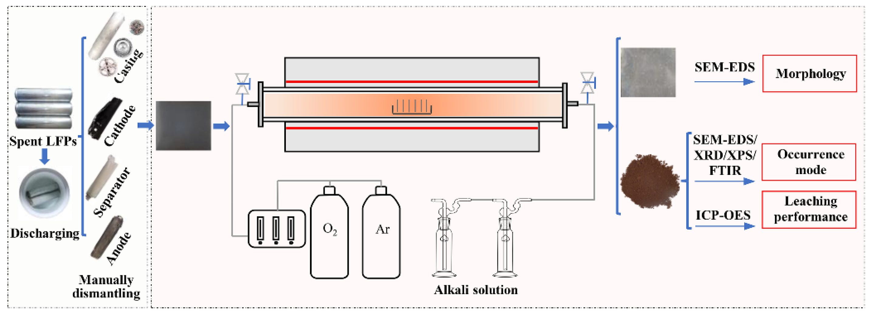
Spent LFPBs offered by ZhongTian Energy Storage Technology Co., Ltd. in China were used in the experiments. The flowsheet of the experimental procedures for the recovery of spent LiFePO4 cathode plates is described in Figure 1.
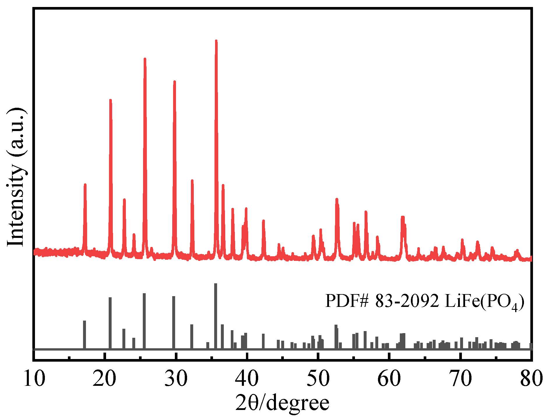
Prior to the oxidizing roasting experiments, a series of pretreatments were taken: First, a 10 wt % NaCl solution was prepared to discharge the remaining capacity for 24 h to prevent the potential dangers of self-ignition and short circuiting [30]; second, the discharged batteries were dismantled to obtain separated cathode plates; third, the cathode plates were further cut into small pieces (5 cm × 5.5 cm). Table 1 presents the chemical composition of the raw cathode materials separated from Al foils. It is observed from Table 1 that the cathode materials contain 14.49% P, 35.11% Fe, 3.43% Li, 13.52% C, and 3.51% F. The XRD pattern of the raw cathode materials shows that the cathode materials only contained LiFePO4 phase (Figure 2).
The experiments of oxidizing roasting were implemented in a tube furnace (GSL-1400X, HF-Kejing, Hefei Kejing materials technology Co., Ltd., Hefei, China) equipped with an atmosphere controller. Six cathode plates were put into a special corundum ark in each experiment, which was then laid into a tubular furnace. The experiments were performed with a preset temperature (450–700 °C) at a heating rate of 10 °C/min, gas flow (20–450 mL/min), and oxygen concentration (0–50 vol.% O2). When the oxidizing roasting finished, the cathode plates were taken out, weighted and sieved for 10 s. The cathode materials were then collected and ground by a planetary ball mill. To study the oxidizing roasting behavior of spent LiFePO4 cathode materials, various characterization methods were applied. The detailed information about the analysis methods is shown in Appendix A.
The leaching performance tests of calcined cathode materials were conducted in a 50 mL conical flask placed in a homoeothermic water bath. The conditions for sulfuric acid leaching system include H2SO4 concentration of 1 M, leaching temperature of 70 °C, and solid–liquid ratio of 25 g·L−1. The solution was filtered after 1 h and the filtrate was analyzed by inductively coupled plasma-atomic emission spectroscopy (ICP-AES) in order to investigate the elemental content of Fe and Li. The residue was washed with ultrapure water and then analyzed by XRD.
In this study, the weight loss rate of cathode plates was calculated as follows:
where (g) is the mass of the cathode plates after thermal treatment and (g) is the total mass of raw cathode plates.
The recovery rate of the cathode materials was described as follows:
where (g) is the mass of cathode materials recovered by thermal treatment and (g) is the total mass of cathode materials.
The leaching rate ηi of metals from the cathode powder was obtained as follows:
where (g·L−1) represents the concentration of element “i”, (L) represents the volume of leachate; (g) is the total mass of cathode powder and is the weight content of element “i”.
3. Results and Discussion
3.1. Effect of Roasting Temperature
To investigate the effect of roasting temperatures on the oxidizing roasting process of spent LiFePO4 cathode plates, the experiments were carried out with increasing temperatures from 450 to 700 °C in steps of 50 °C. A constant air flow rate of 300 mL/min and a roasting time of 30 min were used. The results (shown in Figure 3) clearly indicate that the rise of temperature affects the oxidizing roasting of spent cathode plates significantly.
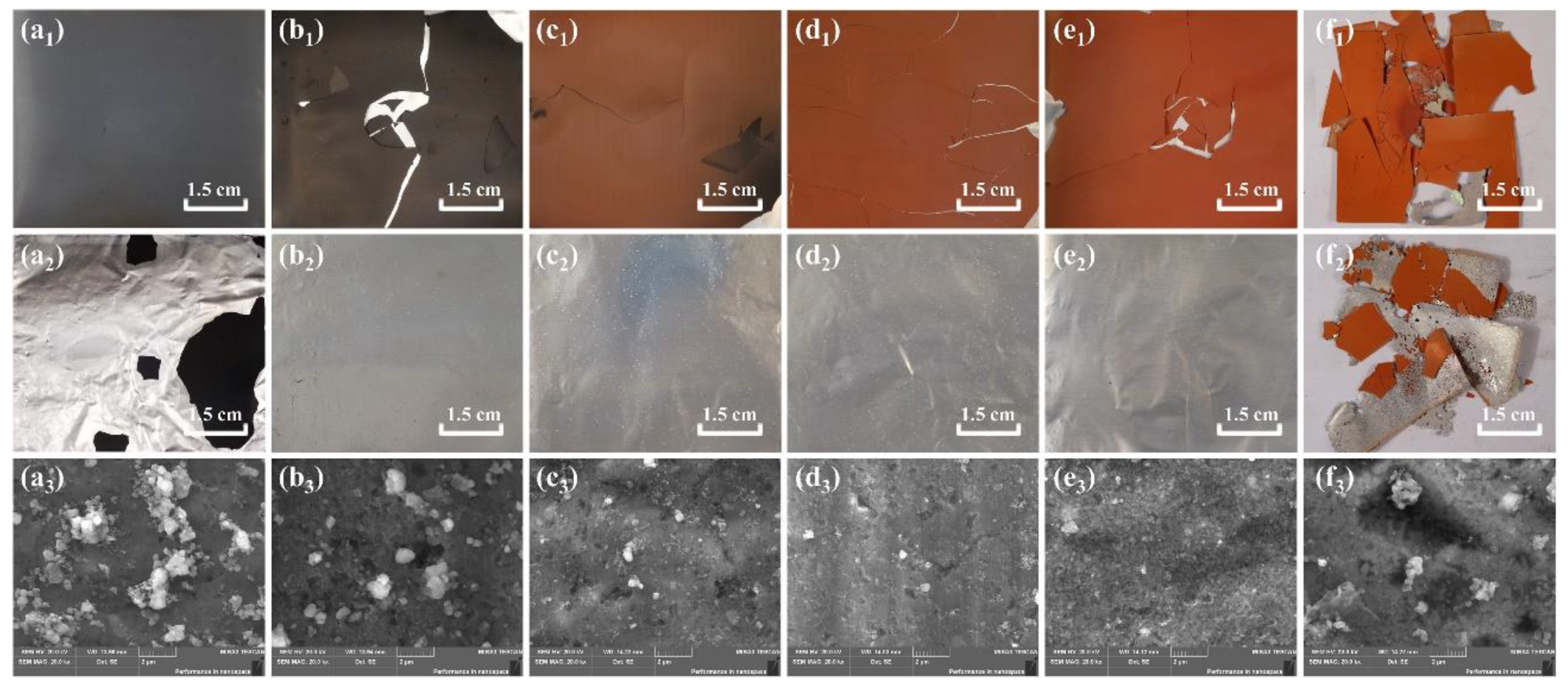
Figure 3a1–f1 present the visual color change of cathode materials, from grey to brick red, as temperature increases. This can be attributed to the oxidation of Fe2+ to Fe3+ during the oxidizing roasting process [29]. The corresponding changes of Al foils obtained by screening can be observed in Figure 3a2–f2. At a roasting temperature of 450 °C, there were a small number of cathode materials adhered to the Al foils, suggesting that the binder was not completely decomposed. At higher roasting temperatures (500 °C to 650 °C), the cathode materials were entirely stripped off from the Al foils. However, at 700 °C, the Al foils were ablated and holes could be noticed. At this temperature, the cathode materials adhered to the Al foils again and were difficult to be separated since the latter melted (the melting point of Al is 660 °C). The morphology of Al foils treated at different temperatures was analyzed by SEM (shown in Figure 3a3–f3). The SEM images indicate that the amount of binder PVDF and cathode materials adhered to the Al foils decreased gradually with increase in roasting temperature. Correspondingly, the surface corrosion and unevenness of the Al foils increased. This can be attributed to the effective oxidative decomposition of binder PVDF during the higher temperature oxidizing roasting process, which released fluorine-containing gases such as hydrogen fluoride (HF), that could corrode the Al foils [31].
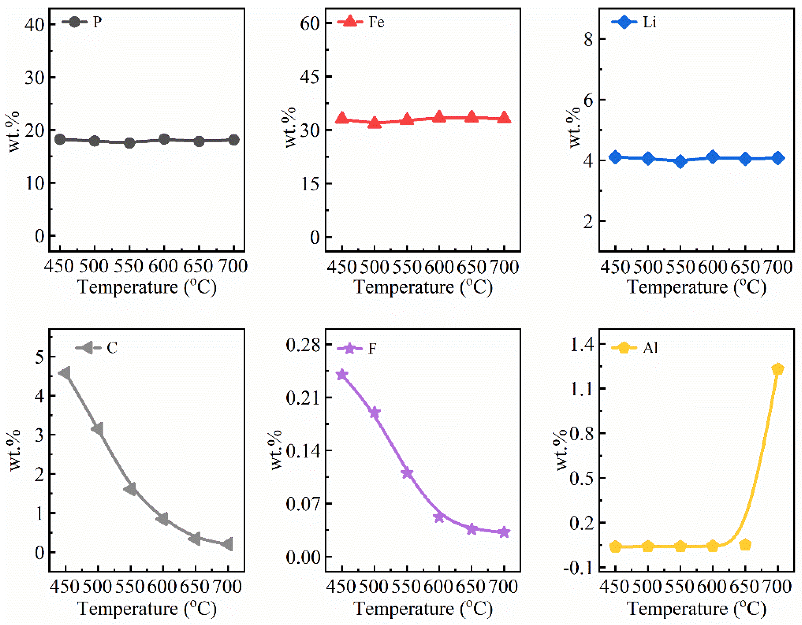
Figure 4 presents the recovery efficiency of cathode materials, weight loss rate of spent LiFePO4 cathode plates and element content in calcined cathode materials at different roasting temperatures. It corresponded to the peeling of cathode materials in Figure 3a2–f2, respectively. The recovery efficiency of cathode materials increased from 77.0% to 99.9% and then dropped to 81.0% at 450–700 °C. In addition, the weight loss rate of spent LiFePO4 cathode plates at different roasting temperatures was also obtained using Equation (1). It is evident that the roasting temperature has a significant influence on the weight loss rate of spent LiFePO4 cathode plates. The weight loss rate increased from 11.0% to 13.9% as the roasting temperature rose from 450 °C to 600 °C. However, when the roasting temperature was over 600 °C, the weight loss rate saturated around 14.0%, implying that the binder was almost completely decomposed. To further study the effects of roasting temperature on cathode materials, the content of P, Fe, Li, C, F, and Al was measured (Figure 4b). The detailed information about the chemical analysis results of calcined cathode materials is shown in Appendix A, Figure A1. It can be observed in Figure A1 that with the increasing roasting temperature during the thermal treatment, the content of P, Fe and Li fluctuated around 18.0%, 33.0% and 4.0%, respectively, while the content of C, F, and Al showed obvious changes with the increase of roasting temperature. The C and F content showed a sharp decrease in the temperature range of 450–600 °C, reducing from 4.58%, 0.24% to 0.85%, 0.052%, respectively. This can be attributed to the rapid decomposition of organic matter. The C and F content was stable from 600 °C to 700 °C, indicating the organic matter was almost completely decomposed. Nevertheless, the Al content showed a different behavior at 450–650 °C. As the roasting temperature rose, the Al content in cathode materials went up from 0.038% to 0.052% slowly, due to the corrosion of Al foils caused by fluorine-containing gases. It surged to 1.23% at 700 °C since the melting of Al foils introduced Al chips into the cathode powder.
The leaching behavior of cathode materials obtained from different roasting temperatures was analyzed by obtaining the leaching efficiency and phase transition using ICP-OES and XRD, respectively.
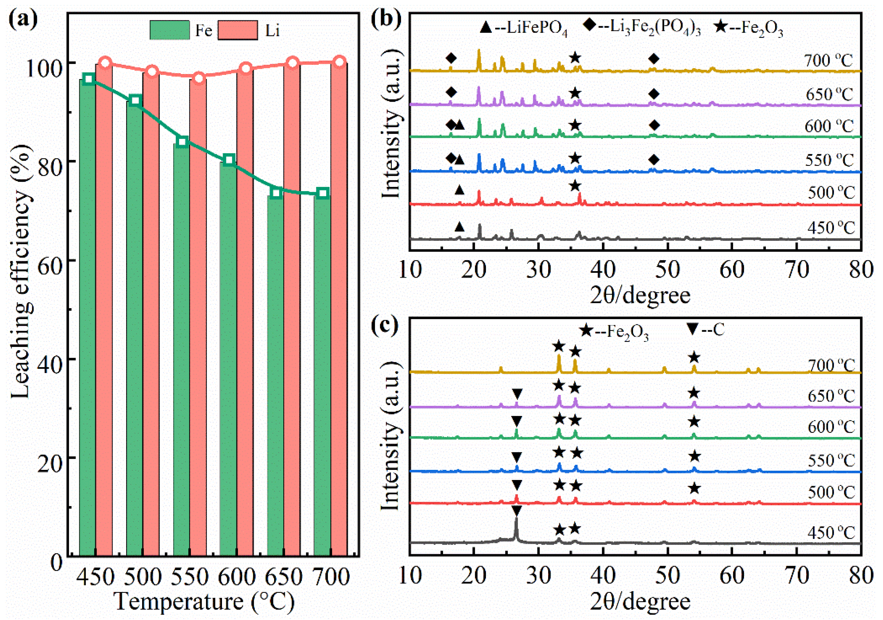
The leaching behavior of Fe and Li in sulfuric acid leaching system are shown in Figure 5a. The roasting temperatures, in the range of 450–700 °C, hardly affected the leaching efficiency of Li, which remained above 97%, because lithium ions inserted in electrode materials are easily released from the Fe-P-O framework as they have higher reactivity than other metals in dilute sulfuric acid solution [32,33]. On the contrary, it significantly impacted the leaching behavior of Fe. The leaching efficiency of Fe was 96.6% at 450 °C, but decreased to 73.02% when the temperature increased to 700 °C. Considering these results, it can be extrapolated that the rise of roasting temperature accelerated the oxidation of LiFePO4 cathode materials. During this period, a large amount of Fe2O3 was produced, resulting in the decrease in amount of Fe leached by dilute sulfuric acid leaching system.
Figure 5b shows the XRD patterns of cathode materials under different roasting temperatures. The major phases of the cathode materials observed after thermal treatment were LiFePO4, Li3Fe2(PO4)3 and Fe2O3. It is consistent with the XRD analysis results in Zheng et al. [29] and Ni et al. [34]. At temperatures below 600 °C, the cathode materials were gradually oxidized to Li3Fe2(PO4)3 and Fe2O3. At 600 °C, the LiFePO4 phase disappeared completely, proving that most of the cathode materials were oxidized. As the temperature further increased, the diffraction peak of both Li3Fe2(PO4)3 and Fe2O3 slowly increased. Based on the above results, the oxidation of LiFePO4 cathode materials can be presented as follow Equation (4) [29,34,35].
The XRD patterns of sulfuric acid leaching residue of cathode materials shown in Figure 5c clearly indicate that the major phases were Fe2O3 and C. Compared to Figure 5b, the phases of LiFePO4 and Li3Fe2(PO4)3 disappeared. This demonstrated that the crystalline structure of cathode materials disintegrated and water-soluble sulfates of Li and Fe formed. In addition, the existence of the phase of Fe2O3 implied that the ferric oxide with high valence was hard to be reduced. It is also notable that the diffraction peaks of C decreased with the increase of roasting temperature, until they disappeared at 700 °C, where the binder was removed completely. Different from C, the diffraction peaks of Fe2O3 gradually increased, consistent with the decreased leaching efficiency of Fe in Figure 5a.
Based on the above results, 500 °C was selected as the optimum roasting temperature for subsequent experiments exploring the effect of oxygen concentration.
3.2. Effect of Oxygen Concentration
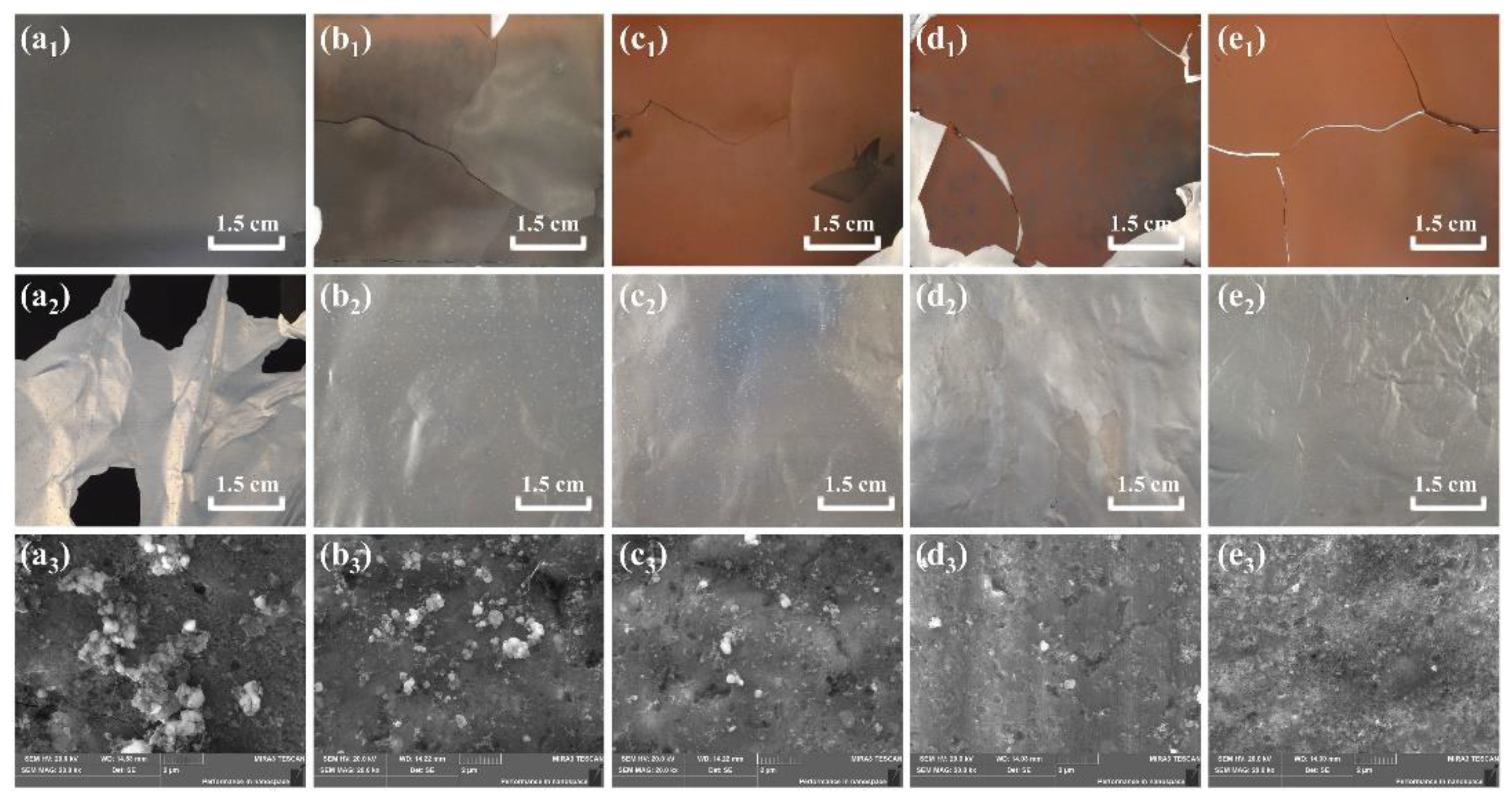
The relationship between oxygen concentration and oxidizing roasting process of spent LFPBs plates is another important research object. The experiment was set up with a constant roasting temperature of 500 °C, a gas flow rate of 300 mL/min, and a roasting time of 30 min. As presented in Figure 6, the oxygen concentration is closely related to the oxidizing roasting of spent cathode plates. Figure 6a1–e1, clearly reveal the color change of cathode materials, indicating that the increased oxygen concentration accelerated the oxidation of cathode materials. The changes in Al foils obtained by screening are shown in Figure 6a2–e2. Some cathode materials still attached to the Al foils at 0 vol.% (Nitrogen atmosphere) oxygen concentration. As the oxygen concentration rose from 5 vol.% to 50 vol.%, the cathode materials were completely peeled from the Al foils. The possible explanation is that oxygen sped up the oxidative decomposition of binder PVDF. Similar changes were observed when investigating the micromorphology of Al foils (Figure 6a3–e3). The SEM images reveal that as the oxygen concentration increased, the residual binder PVDF and LiFePO4 cathode materials gradually reduced and totally disappeared when the oxygen concentration reached 50 vol.%.
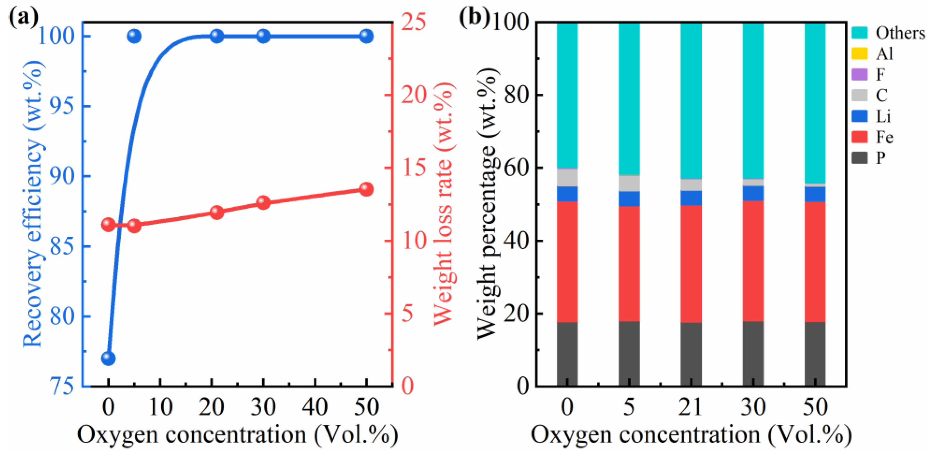
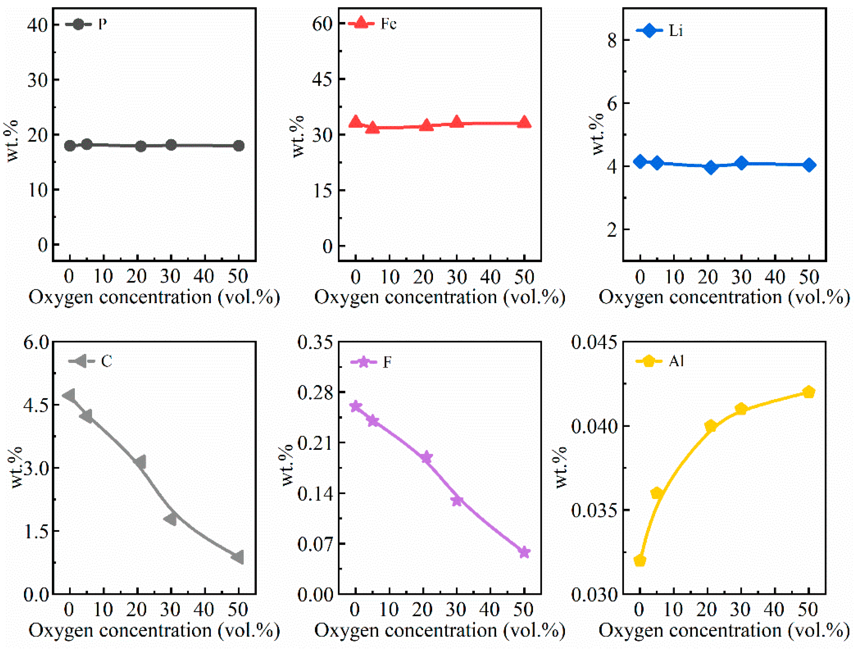
The recovery efficiency of cathode materials and the weight loss rate of cathode plates under different oxygen concentrations are shown in Figure 7a. The recovery efficiency of cathode materials rose sharply from 77% to 99.9% when the oxygen concentration increased from 0 vol.% to 5 vol.%. When the oxygen concentration exceeded 5 vol.%, the recovery efficiency reached about 100%. A slight decrease (11.09–11.02%) in the weight loss rate was detected when the oxygen concentration increased from 0 vol.% to 5 vol.% because the mass of introduced oxygen was greater than the volatilization and decomposition mass of organic compounds. However, the weight loss rate tended to increase continuously when the oxygen concentration exceeded 5 vol.%. The effects of oxygen concentration on the element content in calcined cathode materials are presented in Figure 7b. Figure A2 in Appendix A presents the detailed information regarding the chemical compositions of calcined cathode materials. The content of P, Fe, and Li changed around 18.0%, 33.0%, and 4.0%, respectively. Both the C and F content declined with the increase of oxygen concentration, but the Al content behaved in an opposite way (0.032% to 0.042%). This behavior can be reasoned by the intensified oxidative decomposition of binder PVDF resulting in decreased C and F content, while simultaneously increasing the Al content due the release of corrosive fluorine-containing gases.
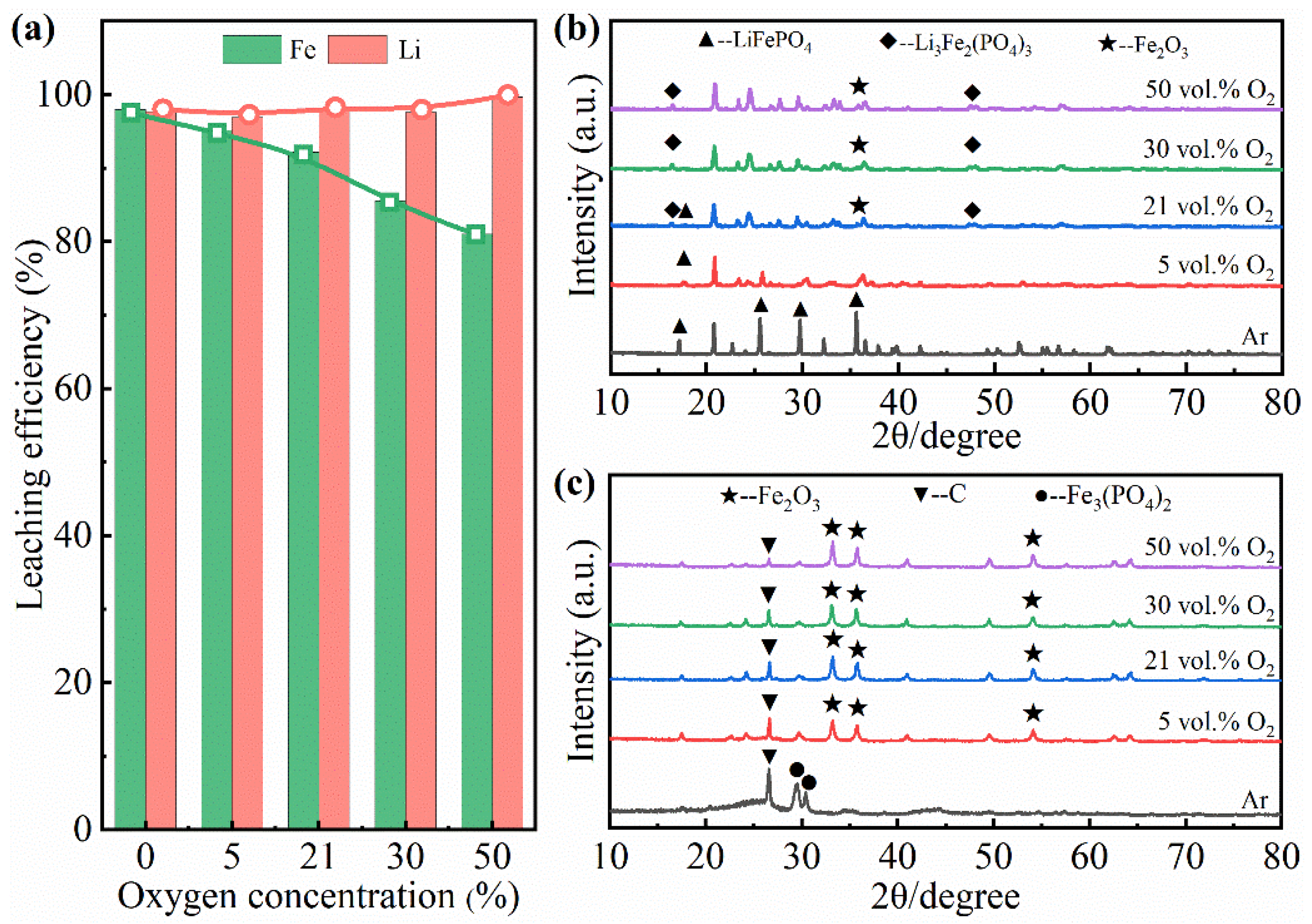
The leaching behavior of cathode materials obtained from different oxygen concentrations was further analyzed using ICP-OES and XRD tests. As depicted in Figure 8a, the Li leaching efficiency remained constant at around 100%, while the leaching efficiency of Fe decreased from 98.01% to 79.9% as the oxygen concentration increased. The phase composition of calcined cathode materials and sulfuric acid leaching residue were also analyzed at different air flow rates. The oxygen concentration was closely associated with the phase change of cathode materials (Figure 8b). At 0 vol.% oxygen concentration, the only phase that existed was LiFePO4. With the increase of oxygen concentration, the diffraction peaks of Li3Fe2(PO4)3 and Fe2O3 appeared and kept increasing. The LiFePO4 peaks gradually faded away when the oxygen concentration was over 21 vol.%. Compared to the calcined cathode materials, LiFePO4 and Li3Fe2(PO4)3 disappeared and the major phases were Fe2O3, C, and Fe3(PO4)2 in sulfuric acid leaching residue (Figure 8c).
On the basis of the above findings, 21 vol.% O2 was considered to be the optimum oxygen concentration for the experiments investigating the effect of gas flow.
3.3. Effect of Gas Flow
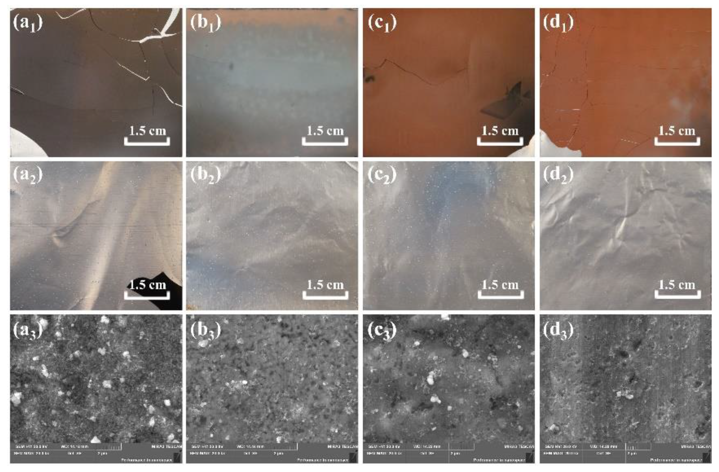
The last research object related to the oxidizing roasting process of spent LiFePO4 cathode plates was gas flow. The experiment was conducted under a roasting temperature of 500 °C and an oxygen concentration of 21 vol.%. As seen in Figure 9a1–a3, the cathode materials were grey when the air flow rate was 20 mL/min. Residual binders and cathode materials adhered to the surface of Al foils. As the air flow rate increased to 150 mL/min, the cathode materials became dark brown (Figure 9b1), suggesting that part of cathode materials was oxidized. In addition, there were less binder and cathode materials adhered to Al foil (Figure 9b2,b3). When the air flow rate reached 300 mL/min, the cathode materials turned darker brown (Figure 9c1) and were entirely stripped off from the Al foil (Figure 9c2). The corresponding SEM image (Figure 9c3) indicates that only a limited amount of cathode materials was left. At an air flow rate of 450 mL/min, most of the cathode materials were oxidized (Figure 9d1), and the binder and cathode materials thoroughly vanished from the Al foil (Figure 9d2,d3).
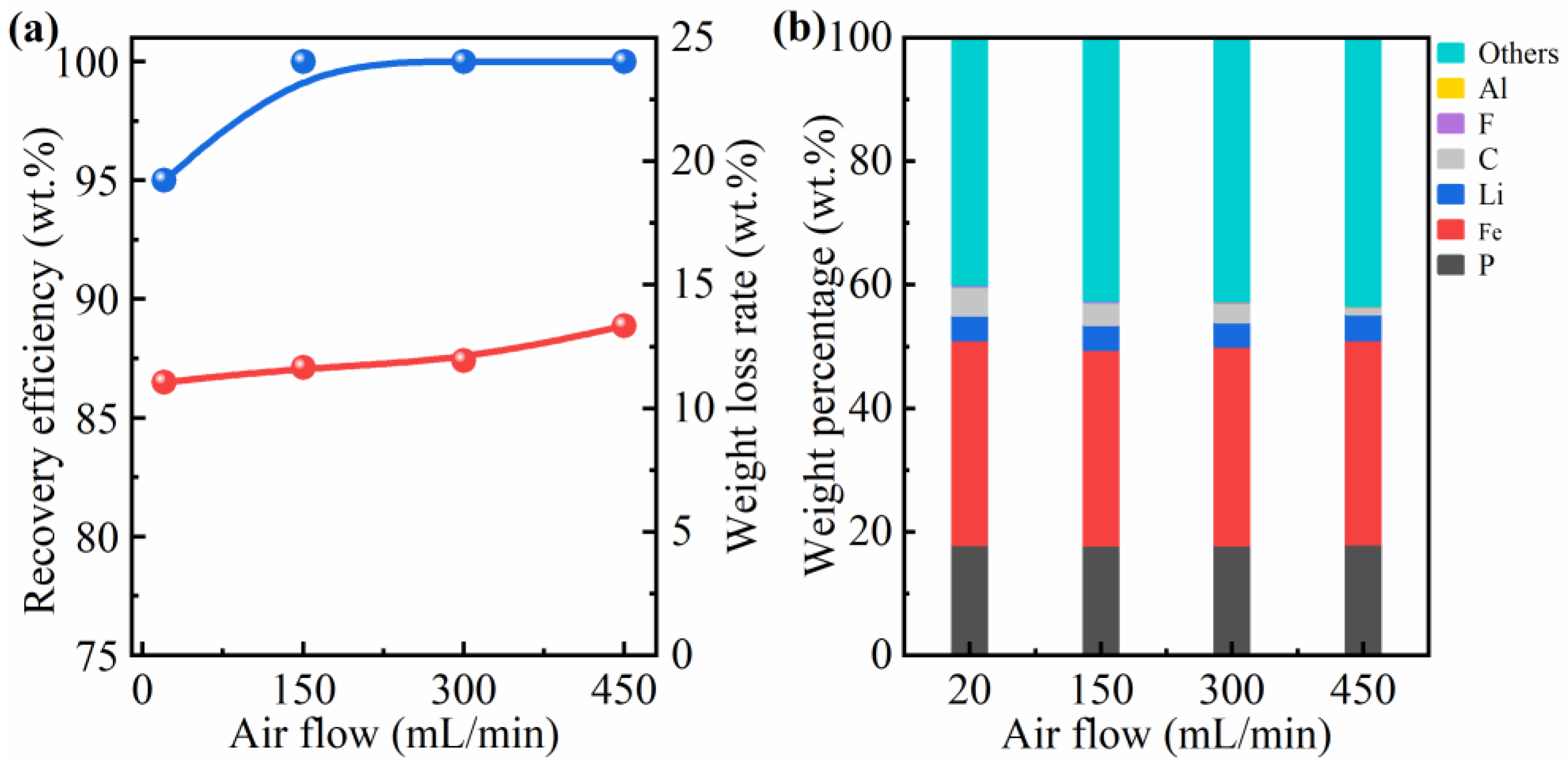
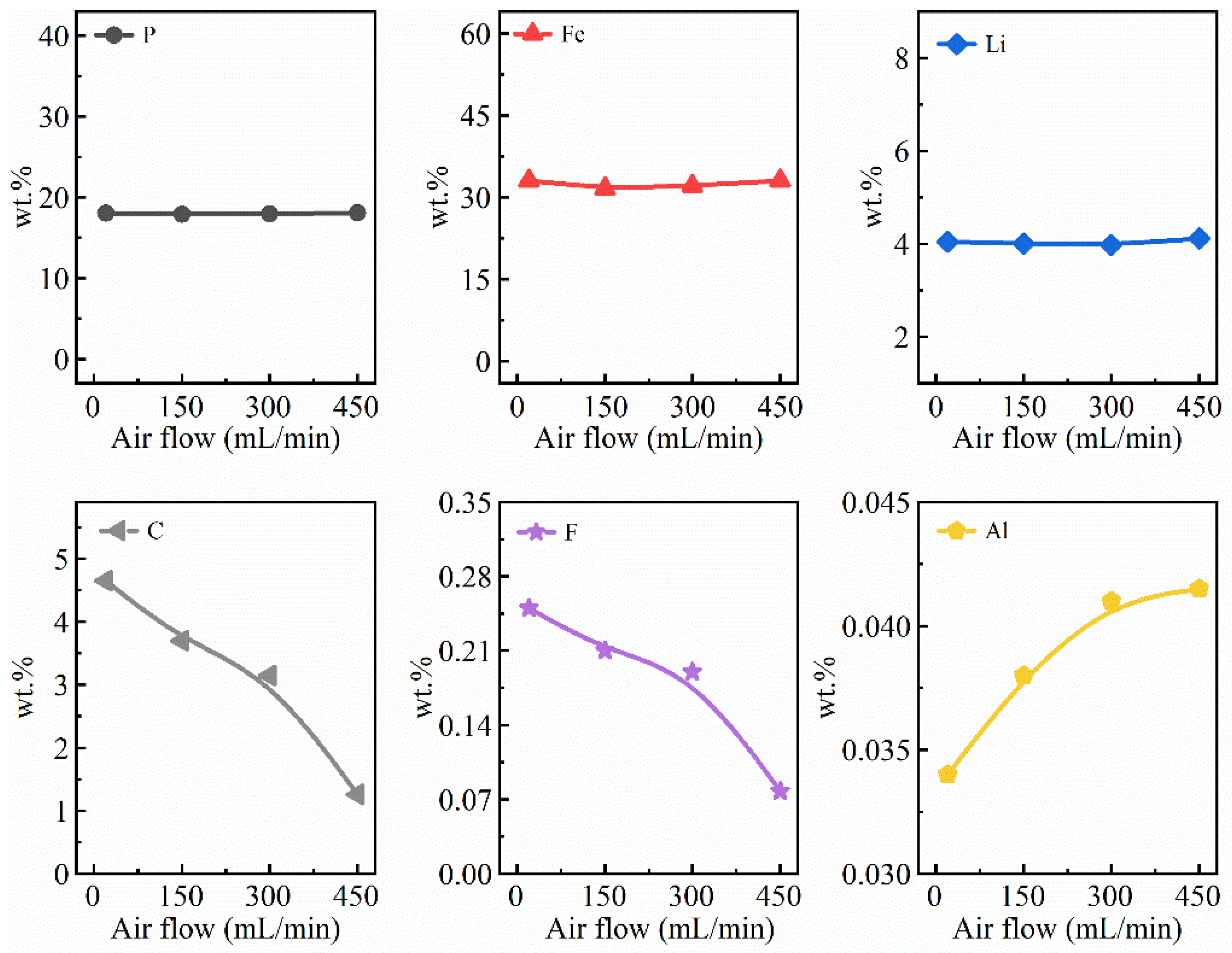
The recovery efficiency of cathode materials and the weight loss rate of spent LiFePO4 cathode plates at different air flow rates estimated during the experiment are presented in Figure 10a. As the air flow rate increased from 20 mL/min to 150 mL/min, the recovery efficiency of cathode materials rose by around 5.0% (from 95% to 99.9%) and the weight loss rate increased from 11.05% to 13.33%. When the air flow rate exceeded 150 mL/min, the cathode materials remained a high recovery efficiency (about 100%) and the weight loss rate of spent LFPBs cathode plates showed an increase trend (11.05–13.33%). The effects of air flow on the element content in calcined cathode materials are illustrated in Figure 10b. Their chemical compositions are shown in Appendix A, Figure A3.
Temperature had little effect on the content of P, Fe, and Li, which kept around 18.0%, 32.0%, and 4.0%, respectively. The Al content also increased (0.034–0.0415%), due to the corrosion of fluorine-containing gases. Conversely, the C content decreased from 4.65% to 1.26%, and the F content decreased from 0.25% to 0.078%. This denotes that the increase of air flow rate accelerated the oxidative decomposition of binder.
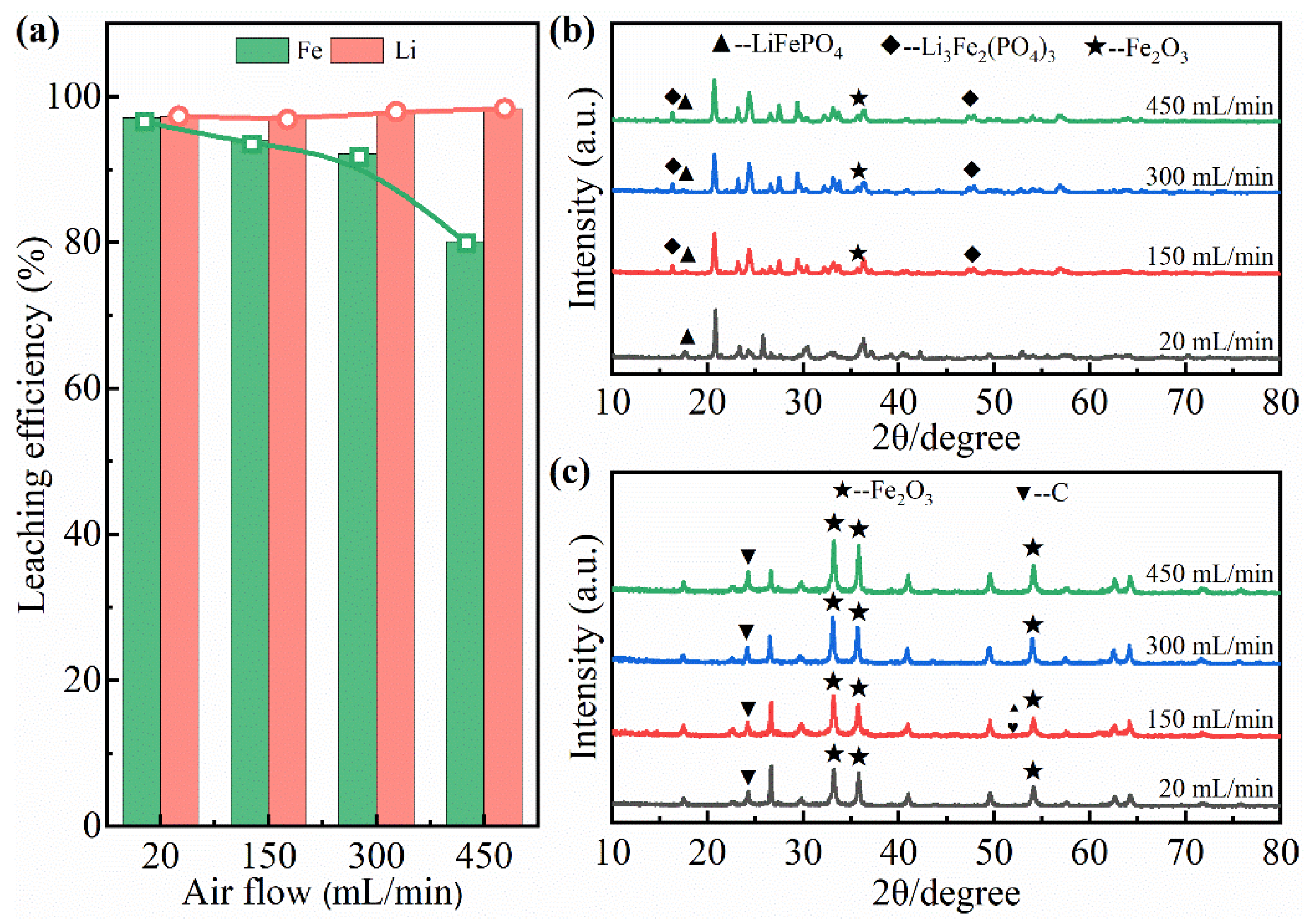
Figure 11a shows the leaching efficiencies of Fe and Li acquired at different air flow rate in the sulfuric acid leaching system. The leaching efficiency of Li was quite stable (over 97%), but that of Fe decreased drastically from 97.12% to 79.5% with the increase of air flow rate. The XRD patterns of cathode materials (Figure 11b) were also analyzed for the different air flow rates. At 20 mL/min, A small amount of cathode materials were oxidized and the major phases of cathode materials were LiFePO4 and Li3Fe2(PO4)3. As the air flow rate increased to 150 mL/min, a new Fe2O3 phase appeared. Further, the diffraction peaks of Li3Fe2(PO4)3 increased compared to previous ones. When the air flow rate rose to 450 mL/min, a continuous growth of diffraction peaks of Li3Fe2(PO4)3 and Fe2O3 was observed. Figure 11c shows the XRD patterns of the leaching residue. The major phases observed were Fe2O3 and C. The diffraction peaks of Fe2O3 increased as the air flow rate increased, which was consistent with the leaching efficiency of Fe.
Taking the results into account, thereupon, 300 mL/min was regarded as the optimum air flow rate for the oxidizing roasting experiment.
3.4. Characterization of Cathode Materials
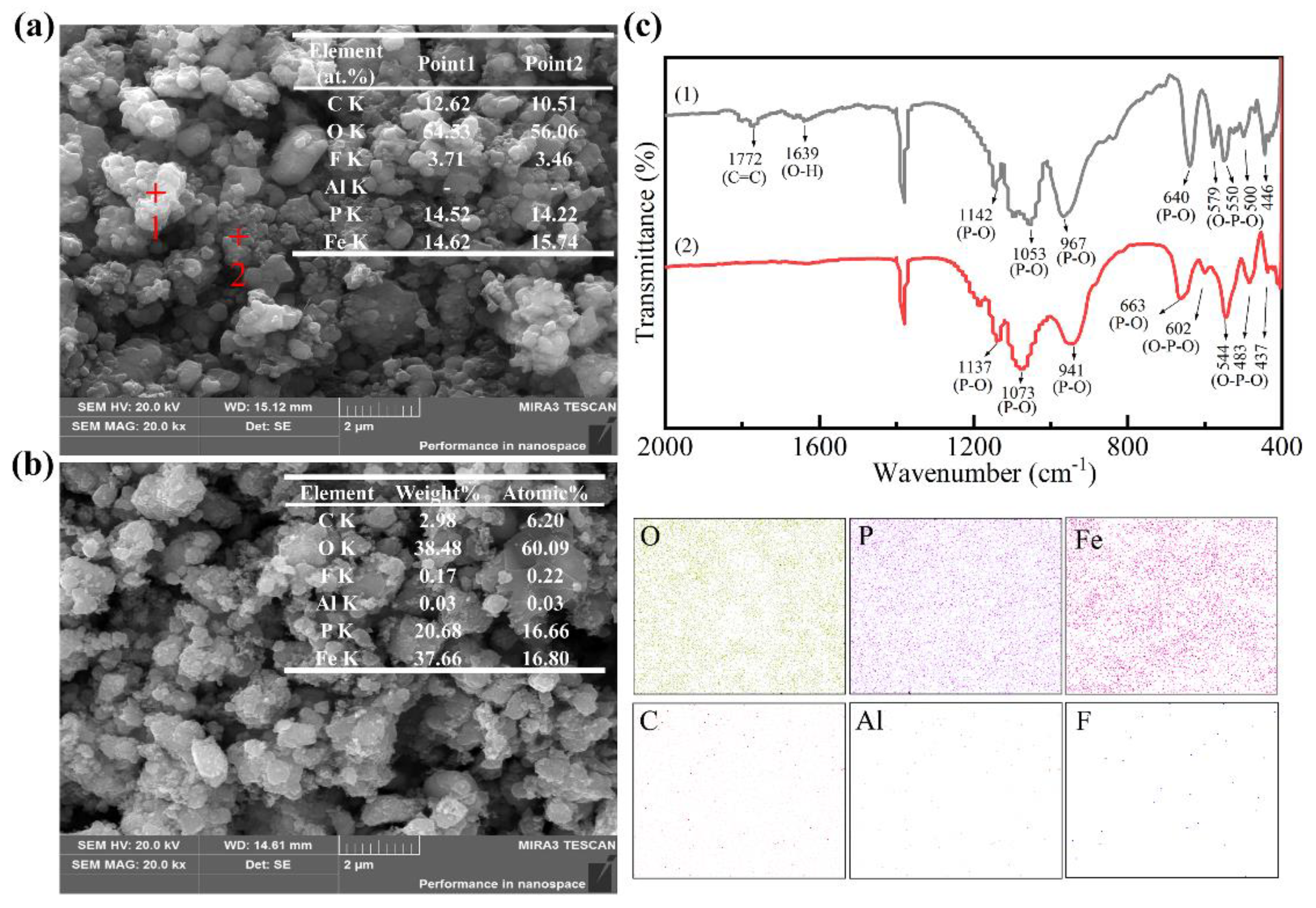
Based on the above experiments, the optimum conditions for the thermal treatment of cathode plates can be summarized as follows: a roasting temperature of 500 °C, an oxygen concentration of 21% and an air flow rate of 300 mL/min. When studying the characterization of materials under these circumstances, more findings surfaced. Figure 12a is an SEM micro-morphology of raw cathode materials that was separated from Al foil. Despite the irregular morphologies, the primary particles were highly agglomerated because of the binder. Points 1 and 2 were further analyzed using EDS. The data obtained indicated that the cathode materials were mainly composed of C, O, F, P, and Fe. More specifically, the mole fractions of C and F were 12.0% and 3.5%, respectively, hinting that large amounts of fluorocarbon materials (e.g., binder PVDF and conductive additives) were present in the cathode materials. In contrast to the raw cathode materials, the cathode materials calcined under the predetermined optimal conditions (Figure 12b) showed much less degree of agglomeration. In addition, the large grains were covered with a variety of small irregular and rough particles, which turned out to be O, P, and Fe in EDS analysis. The C and F content fell sharply. The differences can be attributed to the oxidative decomposition of binder PVDF during the thermal treatment.
The differences in the molecular structure and composition of raw and calcined cathode materials were further investigated using FT-IR tests. Figure 12c depicts the distinct changes of the bending and stretching vibrations of cathode materials before and after oxidizing roasting. The raw cathode materials show the absorption peaks at 1639 cm−1 and 1772 cm−1 disappeared. The band around 1639 cm−1 represents the characteristic of O-H stretching vibration in H2O molecule generated due to the condensation of water in air [28]. The peak around 1772 cm−1 corresponds to the characteristic C=C stretching vibration of the polymer (H2C=CF-R) [32,36]. These peaks are clearly absent in the calcined cathode materials, indicating that the binder was removed in the heating process. The characteristic phosphate group vibrations at the wavenumbers 940–1250 cm−1 and 400–700 cm−1 correspond to the asymmetric stretching vibrations of -PO4 tetrahedron and the bending vibrations of O-P-O, respectively, remain unchanged. Those indicate that the cathode materials still existed as phosphates even after the oxidizing roasting process [37,38].
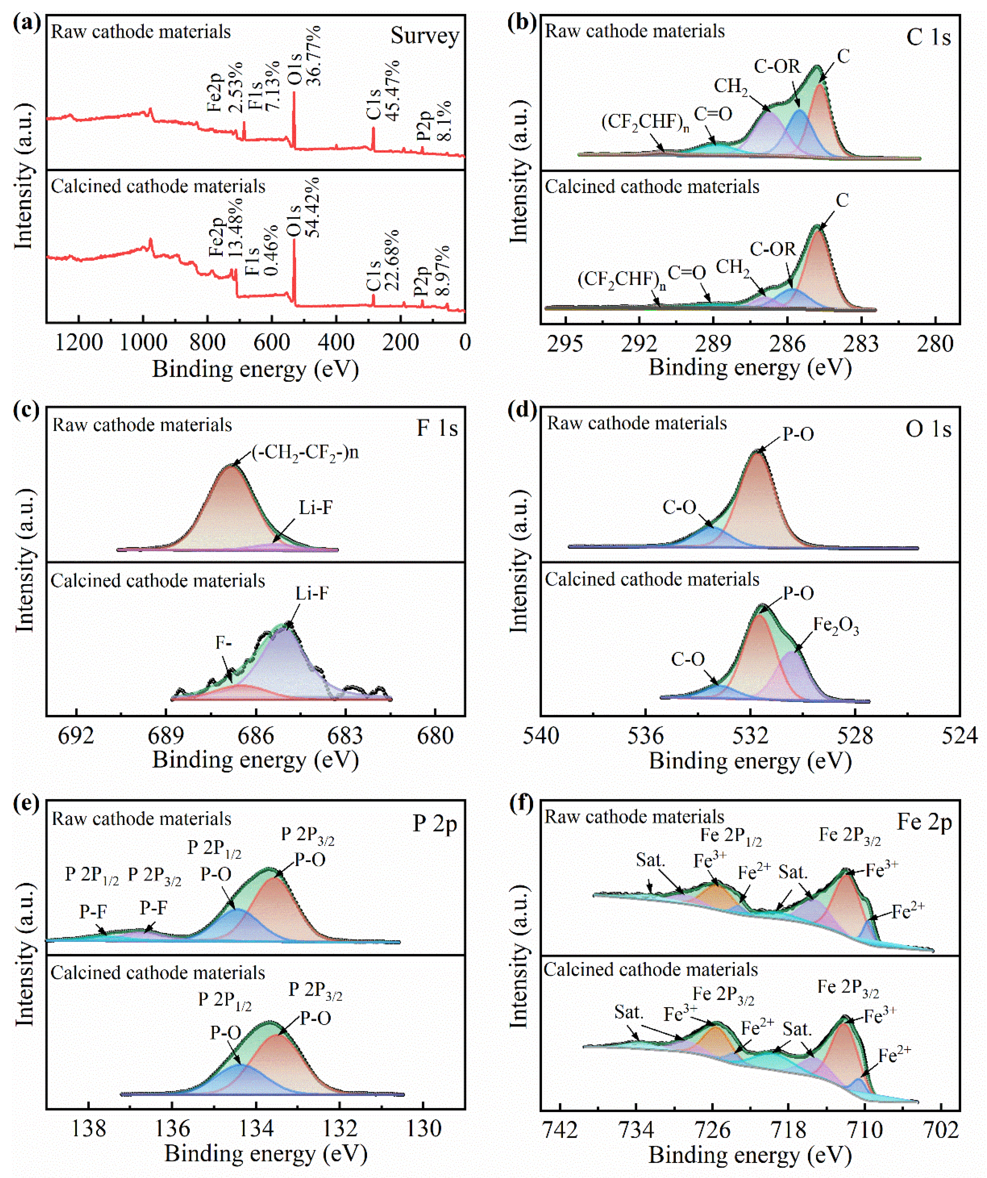
XPS analysis was used to further investigate the changes of surface chemical composition in the raw cathode materials and the calcined cathode materials. The results were shown in Figure 13. The full XPS spectra of cathode materials before and after annealing are shown in Figure 13a. It can be observed that C, F, O, P, and Fe were the main element compositions in the cathode materials. The high contents of F and C in raw cathode materials indicated that LiFePO4 particles were cladded by PVDF. After oxidizing roasting, the content of C and O decreased from 45.47%, 36.77% to 22.68%, 0.46%, respectively, while the content of O increased from 36.77% to 54.42%. This demonstrate that the binder PVDF was decomposed effectively and some cathode materials were oxidized. Figure 13b presents the spectrum of the C ls region. The main peak at 284.7 eV was caused by the carbon black. Two peaks of C-OR and C=O attributed to organic solvents were detected at 285.5 and 288.9 eV [39]. The peaks located at 286.7 and 291.1 eV are attributed to CH2 and (CF2CHF)n which are from binder PVDF [40]. After oxidizing roasting, the proportion of peaks derived from organic solvents and binder PVDF decreased significantly, further indicating the decomposition of organic compounds during the oxidizing roasting process is effective. Figure 13c exhibits the F 1s spectra before and after oxidizing roasting, the peaks around 685.0 and 686.8 eV correspond to Li-F and (-CH2-CF2-)n, which are assigned to binder PVDF and LiF, respectively [15,40]. After the reaction, it can be observed that the surface concentration of the fluorine species of the calcined cathode materials was remarkably lowered, but F- (686.5 eV) and LiF were still detected. For O 1s, the peaks appeared at 531.7 and 533.3 eV were related to P-O and C-O coming from the phosphate groups (PO43−) and oxygenated species adsorbed at the surface, respectively [41]. After oxidizing roasting, an additional peak located at 530.3 eV demonstrates the formation of oxidation product Fe2O3. Figure 13e shows the P 2p spectrum made of two doublets (2p3/2 and 2p1/2). The first P 2p peak at around 133.7 eV was attributed to P-O bonds in phosphate groups and the second one at around 137 eV was related to P-F bonds in LiPF6 [15]. The Fe 2p spectrum in Figure 13f shows that the spin-orbit doublets of 2p3/2 and 2p1/2 situated at around 712 and 725 eV, respectively. Each of them consists of two main peaks and two satellite peaks, respectively. The peaks at around 710 and 723 eV were assigned to Fe(II), and the peaks appeared at around 712 and 725.5 eV were related to Fe(III) [42]. The changes in the proportion of Fe(II) and Fe(III) suggest the oxidation of LiFePO4 cathode materials during the oxidizing roasting.
4. Conclusions
The oxidizing roasting behavior of spent LiFePO4 cathode plates and leaching performance of cathode materials in sulfuric acid system were investigated systematically in this work. Roasting temperature, oxygen concentration, and air flow rate were detected to obtain the optimum conditions for recovery of spent LFPBs. The key findings of this work are summarized as follows:
(1) When temperature is below 650 °C, the increase of roasting temperature, oxygen concentration, and air flow rate enhanced the liberation of cathode materials. The oxidative decomposition of binder PVDF was intensified. Correspondingly, the Al content increased slowly but the C and F content in the cathode materials decreased sharply.
(2) In general, the cathode materials were gradually oxidized to Li3Fe2(PO4)3 and Fe2O3 during thermal treatment. The increasing Fe2O3 led to a slow decline in the leaching rate of Fe since Fe2O3 cannot be leached effectively in dilute sulfuric acid leaching system. XRD analysis further confirmed that the leaching residue was mainly composed of Fe2O3 and C.
(3) The SEM-EDS, FT-IR, and XPS analysis indicated that the agglomeration degree of calcined cathode materials was far less than that of raw cathode materials. In addition, the binder PVDF was effectively removed and part of cathode materials were oxidized in the heating process.
(4) Considering the high recovery rate, high leaching rate, few hazardous impurities, and low cost, the optimum conditions for thermal treatment of cathode plates were determined as: roasting temperature 500 °C, oxygen concentration 21% O2, and air flow rate 300 mL/min.
Author Contributions
Y.J. contributed to the works of literature search, experimental, figures, data collection, data analysis, and writing and editing; S.Y. contributed to the conceptualization and supervising works; D.Z. contributed to the data collection; Y.L. (Yun Li) contributed to the design of the work. Y.C. played a contributor role of study design, data interpretation, and project administration; Y.L. (Yanqing Lai) contributed the work of review and editing and final approval of the version to be published. All authors have read and agreed to the published version of the manuscript.
Funding
This work was funded by the Hunan Provincial Key Research and Development Projects (Social Development) (Grant No. 2019SK2061).
Conflicts of Interest
The authors declare no conflict of interest.
Appendix A
The phase composition of cathode materials was examined by XRD (Rigaku, TTR-Ⅲ, Cu Kα, Tokyo, Japan) and FT-IR (Nicolet 6700, Thermo Fisher Scientific, Waltham, MA, USA). The surface morphology of cathode materials and Al foils were characterized by SEM (TESCAN MIRA3 LMU, TESCAN ORSAY HOLDING, Brno, The Czech Republic) and EDS (Oxford X-Max20, Oxford Instruments, Oxford, UK). The surface properties of cathode materials were detected by XPS (ESCALAB 250Xi spectrometer, Thermo Scientific, Waltham, MA, USA). The P, Fe, Li, and Al content in cathode materials were examined by inductively coupled plasma-atomic emission spectroscopy (ICP-AES, Optima 5300 DV, Perkin Elmer, Shelton, CT, USA). The C content of cathode materials was characterized by carbon-sulfur analyzer (CS-600, LECO Corporation, St Joseph, MI, USA), and the fluoride ion selective electrode method was employed to measure the F content of cathode materials.
Figure A1.
Chemical analysis of calcined cathode materials obtained at different roasting temperatures.
Figure A1.
Chemical analysis of calcined cathode materials obtained at different roasting temperatures.

Figure A2.
Chemical analysis of calcined cathode materials obtained at different oxygen concentrations.
Figure A2.
Chemical analysis of calcined cathode materials obtained at different oxygen concentrations.

Figure A3.
Chemical analysis of calcined cathode materials obtained at different air flow rates.

References
- Zou, H.; Gratz, E.; Apelian, D.; Wang, Y. A novel method to recycle mixed cathode materials for lithium ion batteries. Green Chem. 2013, 15, 1183. [Google Scholar] [CrossRef]
- Li, L.; Bian, Y.; Zhang, X.; Yao, Y.; Xue, Q.; Fan, E.; Wu, F.; Chen, R. A green and effective room-temperature recycling process of LiFePO4 cathode materials for lithium-ion batteries. Waste Manag. 2019, 85, 437–444. [Google Scholar] [CrossRef] [PubMed]
- Wang, W.; Wu, Y. An overview of recycling and treatment of spent LiFePO4 batteries in China. Resour. Conserv. Recy 2017, 127, 233–243. [Google Scholar] [CrossRef]
- Liu, C.; Lin, J.; Cao, H.; Zhang, Y.; Sun, Z. Recycling of spent lithium-ion batteries in view of lithium recovery: A critical review. J. Clean. Prod. 2019, 228, 801–813. [Google Scholar] [CrossRef]
- Zeng, X.; Li, J.; Singh, N. Recycling of Spent Lithium-Ion Battery: A Critical Review. Crit. Rev. Environ. Sci. Technol. 2014, 44, 1129–1165. [Google Scholar] [CrossRef]
- Heelan, J.; Gratz, E.; Zheng, Z.; Wang, Q.; Chen, M.; Apelian, D.; Wang, Y. Current and Prospective Li-Ion Battery Recycling and Recovery Processes. JOM 2016, 68, 2632–2638. [Google Scholar] [CrossRef] [Green Version]
- Huang, B.; Pan, Z.; Su, X.; An, L. Recycling of lithium-ion batteries: Recent advances and perspectives. J. Power Sources 2018, 399, 274–286. [Google Scholar] [CrossRef]
- Natarajan, S.; Aravindan, V. Burgeoning Prospects of Spent Lithium-Ion Batteries in Multifarious Applications. Adv. Energy Mater. 2018, 8, 1802303. [Google Scholar] [CrossRef]
- Yao, Y.; Zhu, M.; Zhao, Z.; Tong, B.; Fan, Y.; Hua, Z. Hydrometallurgical Processes for Recycling Spent Lithium-Ion Batteries: A Critical Review. ACS Sustain. Chem. Eng. 2018, 6, 13611–13627. [Google Scholar] [CrossRef]
- Zeng, X.; Li, J.; Liu, L. Solving spent lithium-ion battery problems in China: Opportunities and challenges. Renew. Sust. Energ. Rev. 2015, 52, 1759–1767. [Google Scholar] [CrossRef]
- Lv, W.; Wang, Z.; Cao, H.; Sun, Y.; Zhang, Y.; Sun, Z. A Critical Review and Analysis on the Recycling of Spent Lithium-Ion Batteries. ACS Sustain. Chem. Eng. 2018, 6, 1504–1521. [Google Scholar] [CrossRef]
- Zhang, X.; Xie, Y.; Lin, X.; Li, H.; Cao, H. An overview on the processes and technologies for recycling cathodic active materials from spent lithium-ion batteries. J. Mater. Cycles Waste Manag. 2013, 15, 420–430. [Google Scholar] [CrossRef]
- Li, J.-H.; Li, X.-H.; Zhang, Y.-H.; Hu, Q.-Y.; Wang, Z.-X.; Zhou, Y.-Y.; Fu, F.-M. Study of spent battery material leaching process. Trans. Nonferrous Met. Soc. China 2009, 19, 751–755. [Google Scholar] [CrossRef]
- Zhang, T.; He, Y.; Wang, F.; Ge, L.; Zhu, X.; Li, H. Chemical and process mineralogical characterizations of spent lithium-ion batteries: An approach by multi-analytical techniques. Waste Manag. 2014, 34, 1051–1058. [Google Scholar] [CrossRef] [PubMed]
- Zhang, T.; He, Y.; Wang, F.; Li, H.; Duan, C.; Wu, C. Surface analysis of cobalt-enriched crushed products of spent lithium-ion batteries by X-ray photoelectron spectroscopy. Sep. Purif. Technol. 2014, 138, 21–27. [Google Scholar] [CrossRef]
- Yang, L.; Xi, G.; Xi, Y. Recovery of Co, Mn, Ni, and Li from spent lithium ion batteries for the preparation of LiNixCoyMnzO2 cathode materials. Ceram. Int. 2015, 41, 11498–11503. [Google Scholar] [CrossRef]
- Yao, L.; Feng, Y.; Xi, G. A new method for the synthesis of LiNi1/3Co1/3Mn1/3O2 from waste lithium ion batteries. RSC Adv. 2015, 5, 44107–44114. [Google Scholar] [CrossRef]
- Song, X.; Hu, T.; Liang, C.; Long, H.L.; Zhou, L.; Song, W.; You, L.; Wu, Z.S.; Liu, J.W. Direct regeneration of cathode materials from spent lithium iron phosphate batteries using a solid phase sintering method. RSC Adv. 2017, 7, 4783–4790. [Google Scholar] [CrossRef] [Green Version]
- Wang, L.; Li, J.; Zhou, H.; Huang, Z.; Tao, S.; Zhai, B.; Liu, L.; Hu, L. Regeneration cathode material mixture from spent lithium iron phosphate batteries. J. Mater. Sci. Mater. Electron. 2018, 29, 9283–9290. [Google Scholar] [CrossRef]
- Nan, J.; Han, D.; Zuo, X. Recovery of metal values from spent lithium-ion batteries with chemical deposition and solvent extraction. J. Power Sources 2005, 152, 278–284. [Google Scholar] [CrossRef]
- Chen, L.; Tang, X.; Zhang, Y.; Li, L.; Zeng, Z.; Zhang, Y. Process for the recovery of cobalt oxalate from spent lithium-ion batteries. Hydrometallurgy 2011, 108, 80–86. [Google Scholar] [CrossRef]
- Chen, J.; Li, Q.; Song, J.; Song, D.; Zhang, L.; Shi, X. Environmentally friendly recycling and effective repairing of cathode powders from spent LiFePO4 batteries. Green Chem. 2016, 18, 2500–2506. [Google Scholar] [CrossRef]
- Li, X.; Zhang, J.; Song, D.; Song, J.; Zhang, L. Direct regeneration of recycled cathode material mixture from scrapped LiFePO4 batteries. J. Power Sources 2017, 345, 78–84. [Google Scholar] [CrossRef]
- Paulino, J.F.; Busnardo, N.G.; Afonso, J.C. Recovery of valuable elements from spent Li-batteries. J. Hazard. Mater. 2008, 150, 843–849. [Google Scholar] [CrossRef] [PubMed]
- Granata, G.; Pagnanelli, F.; Moscardini, E.; Takacova, Z.; Havlik, T.; Toro, L. Simultaneous recycling of nickel metal hydride, lithium ion and primary lithium batteries: Accomplishment of European Guidelines by optimizing mechanical pre-treatment and solvent extraction operations. J. Power Sources 2012, 212, 205–211. [Google Scholar] [CrossRef]
- Hanisch, C.; Loellhoeffel, T.; Diekmann, J.; Markley, K.J.; Haselrieder, W.; Kwade, A. Recycling of lithium-ion batteries: A novel method to separate coating and foil of electrodes. J. Clean. Prod. 2015, 108, 301–311. [Google Scholar] [CrossRef]
- Yang, Y.; Huang, G.; Xu, S.; He, Y.; Liu, X. Thermal treatment process for the recovery of valuable metals from spent lithium-ion batteries. Hydrometallurgy 2016, 165, 390–396. [Google Scholar] [CrossRef]
- Lee, C.K.; Rhee, K.-I. Preparation of LiCoO2 from spent lithium-ion batteries. J. Power Sources 2002, 109, 17–21. [Google Scholar] [CrossRef]
- Zheng, R.; Zhao, L.; Wang, W.; Liu, Y.; Ma, Q.; Mu, D.; Li, R.; Dai, C. Optimized Li and Fe recovery from spent lithium-ion batteries via a solution-precipitation method. RSC Adv. 2016, 6, 43613–43625. [Google Scholar] [CrossRef]
- Ojanen, S.; Lundstrom, M.; Santasalo-Aarnio, A.; Serna-Guerrero, R. Challenging the concept of electrochemical discharge using salt solutions for lithium-ion batteries recycling. Waste Manag. 2018, 76, 242–249. [Google Scholar] [CrossRef]
- Liu, W.; Zhong, X.; Han, J.; Qin, W.; Liu, T.; Zhao, C.; Chang, Z. Kinetic Study and Pyrolysis Behaviors of Spent LiFePO4 Batteries. ACS Sustain. Chem. Eng. 2018, 7, 1289–1299. [Google Scholar] [CrossRef]
- Chen, X.; Cao, L.; Kang, D.; Li, J.; Zhou, T.; Ma, H. Recovery of valuable metals from mixed types of spent lithium ion batteries. Part II: Selective extraction of lithium. Waste Manag. 2018, 80, 198–210. [Google Scholar] [CrossRef]
- Yang, Y.; Meng, X.; Cao, H.; Lin, X.; Liu, C.; Sun, Y.; Zhang, Y.; Sun, Z. Selective recovery of lithium from spent lithium iron phosphate batteries: A sustainable process. Green Chem. 2018, 20, 3121–3133. [Google Scholar] [CrossRef]
- Ni, J.; Wang, Y. Temperature-driven structural evolution of carbon modified LiFePO4 in air. RSC Adv. 2015, 5, 30537–30541. [Google Scholar] [CrossRef]
- Zhu, S.; Zhou, H.; Miyoshi, T.; Hibino, M.; Honma, I.; Ichihara, M. Self-Assembly of the Mesoporous Electrode Material Li3Fe2(PO4)3 Using a Cationic Surfactant as the Template. Adv. Mater. 2004, 16, 2012–2017. [Google Scholar] [CrossRef]
- Sun, L.; Qiu, K. Vacuum pyrolysis and hydrometallurgical process for the recovery of valuable metals from spent lithium-ion batteries. J. Hazard. Mater. 2011, 194, 378–384. [Google Scholar] [CrossRef]
- Salah, A.; Jozwiak, P.; Garbarczyk, J.; Benkhouja, K.; Zaghib, K.; Gendron, F.; Julien, C. Local structure and redox energies of lithium phosphates with olivine- and Nasicon-like structures. J. Power Sources 2005, 140, 370–375. [Google Scholar] [CrossRef]
- Ravet, N.; Gauthier, M.; Zaghib, K.; Goodenough, J.B.; Mauger, A.; Gendron, F.; Julien, C.M. Mechanism of the Fe3+ reduction at low temperature for LiFePO4 synthesis from a polymeric additive. Chem. Mater. 2007, 19, 2595–2602. [Google Scholar] [CrossRef]
- Zhang, G.; He, Y.; Feng, Y.; Wang, H.; Zhu, X. Pyrolysis-Ultrasonic-Assisted Flotation Technology for Recovering Graphite and LiCoO2 from Spent Lithium-Ion Batteries. ACS Sustain. Chem. Eng. 2018, 6, 10896–10904. [Google Scholar] [CrossRef]
- Wang, M.; Tan, Q.; Liu, L.; Li, J. Efficient Separation of Aluminum Foil and Cathode Materials from Spent Lithium-Ion Batteries Using a Low-Temperature Molten Salt. ACS Sustain. Chem. Eng. 2019, 7, 8287–8294. [Google Scholar] [CrossRef]
- Castro, L.; Dedryvère, R.; Ledeuil, J.B.; Bréger, J.; Tessier, C.; Gonbeau, D. Aging Mechanisms of LiFePO4 // Graphite Cells Studied by XPS: Redox Reaction and Electrode/Electrolyte Interfaces. J. Electrochem. Soc. 2012, 159, A357–A363. [Google Scholar] [CrossRef]
- Castro, L.; Dedryvere, R.; El Khalifi, M.; Lippens, P.E.; Bréger, J.; Tessier, C.; Gonbeau, D. The Spin-Polarized Electronic Structure of LiFePO4 and FePO4 Evidenced by in-Lab XPS. J. Phys. Chem. C 2010, 114, 17995–18000. [Google Scholar] [CrossRef]
Figure 1.
Flowsheet of the experimental process for the recovery of spent LFPBs cathode plates.

Figure 2.
XRD pattern of the raw cathode materials.

Figure 3.
Effect of roasting temperature on spent LiFePO4 cathode plates. (a1–f1) images of cathode plates at 450–700 °C; (a2–f2) images of Al foils at 450–700 °C; (a3–f3) SEM images of Al foils at 450–700 °C.
Figure 3.
Effect of roasting temperature on spent LiFePO4 cathode plates. (a1–f1) images of cathode plates at 450–700 °C; (a2–f2) images of Al foils at 450–700 °C; (a3–f3) SEM images of Al foils at 450–700 °C.

Figure 4.
Effect of roasting temperature on the (a) recovery efficiency of cathode materials, weight loss rate of cathode plates and (b) element content in calcined cathode materials.
Figure 4.
Effect of roasting temperature on the (a) recovery efficiency of cathode materials, weight loss rate of cathode plates and (b) element content in calcined cathode materials.

Figure 5.
Leaching performance of cathode materials obtained at different roasting temperatures under the leaching conditions of 1.0 M H2SO4, S/L = 25 g/L, 70 °C, and 60 min. (a) Leaching efficiencies of Fe and Li; (b) XRD patterns of calcined cathode materials; (c) XRD patterns of sulfuric acid leaching residue.

Figure 6.
Effect of oxygen concentration on spent LiFePO4 cathode plates: (a1–e1) Images of cathode plates at 0–50 vol.% oxygen concentration; (a2–e2) Images of Al foils at 0–50 vol.% oxygen concentration; (a3–e3) SEM images of Al foils at 0–50 vol.% oxygen concentration.
Figure 6.
Effect of oxygen concentration on spent LiFePO4 cathode plates: (a1–e1) Images of cathode plates at 0–50 vol.% oxygen concentration; (a2–e2) Images of Al foils at 0–50 vol.% oxygen concentration; (a3–e3) SEM images of Al foils at 0–50 vol.% oxygen concentration.

Figure 7.
Effect of oxygen concentration on (a) recovery efficiency of cathode materials, weight loss rate of cathode plates, and (b) element content in calcined cathode materials.
Figure 7.
Effect of oxygen concentration on (a) recovery efficiency of cathode materials, weight loss rate of cathode plates, and (b) element content in calcined cathode materials.

Figure 8.
Leaching performance of cathode materials obtained at different oxygen concentrations under the leaching conditions of 1.0 M H2SO4, S/L = 25 g/L, 70 °C, and 60 min. (a) Leaching efficiencies of Fe and Li; (b) XRD patterns of calcined cathode materials; (c) XRD patterns of sulfuric acid leaching residue.

Figure 9.
Effect of air flow on spent LFP cathode plates: (a1–d1) Images of cathode plates at an air flow rate of 20–450 mL/min; (a2–d2) images of Al foils at an air flow rate of 20–450 mL/min; (a3–d3) SEM images of Al foils at an air flow rate of 20–450 mL/min.
Figure 9.
Effect of air flow on spent LFP cathode plates: (a1–d1) Images of cathode plates at an air flow rate of 20–450 mL/min; (a2–d2) images of Al foils at an air flow rate of 20–450 mL/min; (a3–d3) SEM images of Al foils at an air flow rate of 20–450 mL/min.

Figure 10.
Effect of air flow on the (a) recovery efficiency of cathode materials, weight loss rate of cathode plates, and (b) element content in calcined cathode materials.
Figure 10.
Effect of air flow on the (a) recovery efficiency of cathode materials, weight loss rate of cathode plates, and (b) element content in calcined cathode materials.

Figure 11.
Leaching performance of cathode materials obtained at different air flow under the leaching conditions of 1.0 M H2SO4, S/L = 25 g/L, 70 °C, and 60 min. (a) Leaching efficiencies of Fe and Li; (b) XRD patterns of calcined cathode materials; (c) XRD patterns of sulfuric acid leaching residue.

Figure 12.
SEM-EDS and FT-IR spectra of raw cathode materials and calcined cathode materials under optimized condition. (a) SEM image of raw cathode materials; (b) SEM image of calcine cathode materials; (c) FT-IR spectra of raw cathode materials and calcined cathode materials.
Figure 12.
SEM-EDS and FT-IR spectra of raw cathode materials and calcined cathode materials under optimized condition. (a) SEM image of raw cathode materials; (b) SEM image of calcine cathode materials; (c) FT-IR spectra of raw cathode materials and calcined cathode materials.

Figure 13.
Comparison of (a) the full XPS spectrum, (b) C 1s, (c) F 1s, (d) O 1s, (e) P 2p, and (f) Fe 2p in the raw cathode materials and the calcined cathode materials under optimized condition.
Figure 13.
Comparison of (a) the full XPS spectrum, (b) C 1s, (c) F 1s, (d) O 1s, (e) P 2p, and (f) Fe 2p in the raw cathode materials and the calcined cathode materials under optimized condition.


Table 1.
Chemical composition of raw cathode materials.
| Elements | P | Fe | Li | C | F | Al |
|---|---|---|---|---|---|---|
| wt % | 14.49 | 35.11 | 3.43 | 13.52 | 3.51 | - |
Publisher’s Note: MDPI stays neutral with regard to jurisdictional claims in published maps and institutional affiliations. |
© 2020 by the authors. Licensee MDPI, Basel, Switzerland. This article is an open access article distributed under the terms and conditions of the Creative Commons Attribution (CC BY) license (http://creativecommons.org/licenses/by/4.0/).
Share and Cite
MDPI and ACS Style
Jie, Y.; Yang, S.; Li, Y.; Zhao, D.; Lai, Y.; Chen, Y. Oxidizing Roasting Behavior and Leaching Performance for the Recovery of Spent LiFePO4 Batteries. Minerals 2020, 10, 949. https://0-doi-org.brum.beds.ac.uk/10.3390/min10110949
AMA Style
Jie Y, Yang S, Li Y, Zhao D, Lai Y, Chen Y. Oxidizing Roasting Behavior and Leaching Performance for the Recovery of Spent LiFePO4 Batteries. Minerals. 2020; 10(11):949. https://0-doi-org.brum.beds.ac.uk/10.3390/min10110949
Chicago/Turabian StyleJie, Yafei, Shenghai Yang, Yun Li, Duoqiang Zhao, Yanqing Lai, and Yongming Chen. 2020. "Oxidizing Roasting Behavior and Leaching Performance for the Recovery of Spent LiFePO4 Batteries" Minerals 10, no. 11: 949. https://0-doi-org.brum.beds.ac.uk/10.3390/min10110949
Note that from the first issue of 2016, this journal uses article numbers instead of page numbers. See further details here.