
Cutting Resistance Laboratory Testing Methodology for Underwater Coal Mining

Mining and Geology Faculty, University of Belgrade, Djusina 7, 11000 Belgrade, Serbia
*
Author to whom correspondence should be addressed.
Minerals 2021, 11(6), 564; https://0-doi-org.brum.beds.ac.uk/10.3390/min11060564
Submission received: 26 April 2021
/
Revised: 14 May 2021
/
Accepted: 17 May 2021
/
Published: 25 May 2021
(This article belongs to the Section Mineral Exploration Methods and Applications)
Abstract
:The bucket-wheel dredge “Kovin I” for underwater coal mining with bucket-wheel type UCW-450 has been in operation for over 20 years. Based on analyzing the bucket-wheel dredger performance, productivity, maintenance costs, and reliability, a rational decision was made: to rehabilitate the most essential parts of the dredge, including the bucket wheel and the gearbox. However, the selection and construction of the excavator parts were performed on the ground of available laboratory data for digging resistance. The data itself was determined by the testing methodology that did not include the influence of surrounding water pressure at a certain depth of mining. According to the previous findings, it was necessary to develop a specific research and testing program that would involve appropriate laboratory testing of the geomechanical parameters. These were to represent the influence of hydrostatic water pressure on the working environment—coal. Nevertheless, geomechanical laboratory research tests were initially modified to provide reliable data of cutting resistance, especially in the water under different hydrostatic pressures, fully simulating the “in situ” working conditions of mining, i.e., cutting.
1. Introduction
Continuous mining systems, including bucket-wheel excavators (BWE) and bucket-wheel dredges (BWD), have been used in high-volume mining operations for decades. These excavators offer some advantages as compared to the standard mining equipment [1]. The excavator design must reflect specific conditions to realize these advantages and make bucket-wheel dredge operation efficient. Additionally, a sufficient digging force must be available at the digging wheel [2]. Digging conditions strongly influence the excavator productivity and performance [3]. The digging force, F, has three components (tangential, lateral, and forward thrust) [4,5,6,7], perpendicular to each other (Figure 1).
The tangential force is by far the most significant component, and it determines the torque of the bucket-wheel drives. This force is the most crucial factor for determination of the digging power and is generally known as the cutting or digging force [8]. However, in 1937, Garbotz [9] was the first to publish the calculation of digging power of bucket chain excavator that included a resistance coefficient X, which characterized the soil type. Later, in 1939, Wagon [10] designated the power requirement for digging soil as the “specific bucket-wheel power requirement”. Wagon calculated the specific bucket-wheel power requirement by using power consumption measurements on BWE working. In 1937, Kienast [11] studied the cutting process of bucket chain excavators to determine the optimum slice cross-section for the minimum bucket knife wear. Consequently, he mathematically calculated the minimum slice circumference by considering the rounding of bucket corners. Afterward, in 1955, Rasper [12] calculated the digging power of the bucket wheel by taking the specific digging resistance, k, into account, which entirely depended on the type of soil. Lastly, in 1960, Pajer [13] published the general mathematical solution for the “specific digging resistance”, which referred to the mean cross-sectional area of the cut sickle of bucket wheel.
In the past, the relationship between digging material and specific digging resistance for wheel operation has been analyzed both theoretically and practically. The most critical researchers have been Himmel, Limbrek and Marcelli, Brach, Dombrowski, and Kubec [1,14]. However, Kühn published the first experimental determination of the digging force on scrapers, considering the digging resistance of the soil. The values of digging resistance were determined for scrapers, so it is not recommended to be applied to BWE. Himmel [15] shows that the specific digging resistance is the only parameter that is largely independent of the slice cross-sectional area and that it is practically constant. Accordingly, Klige [1] has published test results in which the specific digging resistances depend substantially on soil’s physical and mechanical properties, as long as they show at least a small degree of plasticity. Additionally, Marcelli [16] determined the specific digging resistance as a parabolic function of the cross-section area based on numerous clay soil tests.
Up to date, there are no well-defined and accepted laboratory testing methods to determine the cutting resistance of a material to be excavated, even though several laboratory methods are available to determine the cutting resistance of the material in the seams of surface mines. The Lübeck Works of Orenstein and Koppel developed a wedge test method [1,14,17] to determine cutting resistance for hard and compact soils by measuring the penetration resistance of the bucket knife or tooth in the laboratory on the drilling core samples or block-shaped rock material samples. Consequently, the testing method is most used for determination of the cutting resistance of the material to be excavated.
2. Coal Mining in Underwater Pit “Kovin”
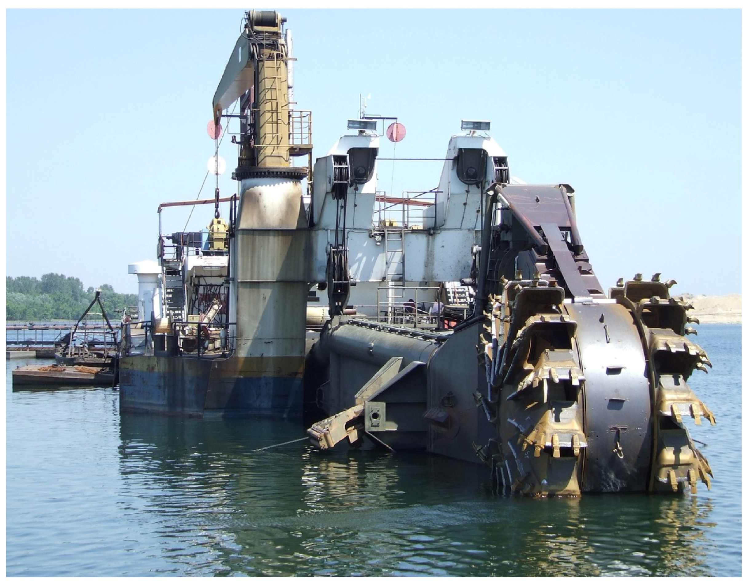
Exploration work in the coal and gravel deposit area began in 1976, while coal exploitation began in 1995. Coal is mined from the bottom of the lake connected to the Danube, and is the only mine with underwater coal exploitation in the world. A continuous technology performs the exploitation of overburden, gravel, and coal in this deposit. In accordance, mining of overburden and gravel is performed by using a bucket-chain dredger “5630” (Figure 2), while coal is excavated using a bucket-wheel dredger “Kovin I” with bucket wheel type UCW-450 [18] (Figure 3).
Bucket-wheel dredge “Kovin I” with bucket wheel type UCW-450 has been used for over 25 years for underwater coal mining [20]. The selection and construction of the excavator parts were performed based on available laboratory data for cutting resistance, which was determined by the standard wedge testing procedure that did not include the influence of water pressure at a certain depth at which coal is mined. The bucket-wheel dredger performance analysis so far has recorded a large difference in cutting resistance, which was especially manifested in the drop of bucket-wheel excavator productivity, increased maintenance costs, and lower reliability.
According to the previous findings, there was a need to rehabilitate the most essential parts of the dredger, bucket wheel, and gearbox. Additionally, it was stated that the digging parameters representing the influence of hydrostatic water pressure on the coal mining process should be studied in detail. The lack of appropriate methodology has led to development of a specific research and testing program to collect relevant data. The testing methodology was initially modified to provide reliable data of cutting resistance per unit of cutting-edge length engaged, KL, and cutting resistance per unit of slice cross-sectional area, KA, especially in the water under different hydrostatic pressures (250–600 kPa), in laboratory conditions simulating the “in situ” working conditions (depth) of mining, i.e., cutting.
3. Geological Settings
Coal and gravel deposit, “Kovin”, represents the northern part of the unique sedimentation area Kostolac-Kovin, which is separated by the Danube [21]. Gravel deposit stratigraphically belongs to the Pleistocene and it was developed in the riverbed facies. Its evolution is continuously present at the entire exploration area. Furthermore, the Kovin coal deposit belongs to the upper Miocene or Pontian stratigraphic unit, actually, the younger part—upper Pontian [22]. In this part of the deposit, the substratum section of the Miocene part are Pontian and Pannonian formations, while overlying strata correspond to quaternary formations (Figure 4).
4. Water Pressure on the Mining Level
The conditions under which it is necessary to determine the value of cutting resistance should as much as possible simulate the conditions that are present during the process of the mining “in situ”. They are determined based on the depth analysis at which the coal exploitation is carried out. The maximum depth at which it is necessary to perform the test is determined since the coal layer is characterized by frequent thickness change, and instead of the second coal layer average depth of 50 m, a maximum depth of 60 m was employed (Figure 5).
5. Methodology of Cutting Resistance Testing
Up to date, there are no well-defined and accepted testing methods to determine the cutting resistance of a material to be excavated. However, several laboratory methods are available to determine the cutting resistance of the material in the seams of surface mines. Nevertheless, the cutting resistance can only be determined by laboratory tests carried out on the drilling core samples or block-shaped rock material samples. The results of laboratory testing allow comparison with test results of rock samples from other mines in which bucket-wheel excavators are already operating. A sufficiently accurate prediction of the cutting resistance can be made only by comparison with the cutting experiences in similar rocks and with the results of laboratory tests. In most cases, the operation of the machines has proven the predictions correct. Generally, the two laboratory testing methods are used to determine the cutting resistance of rock samples, the uniaxial compression test method and the wedge test method.
5.1. Uniaxial Compression Test Method
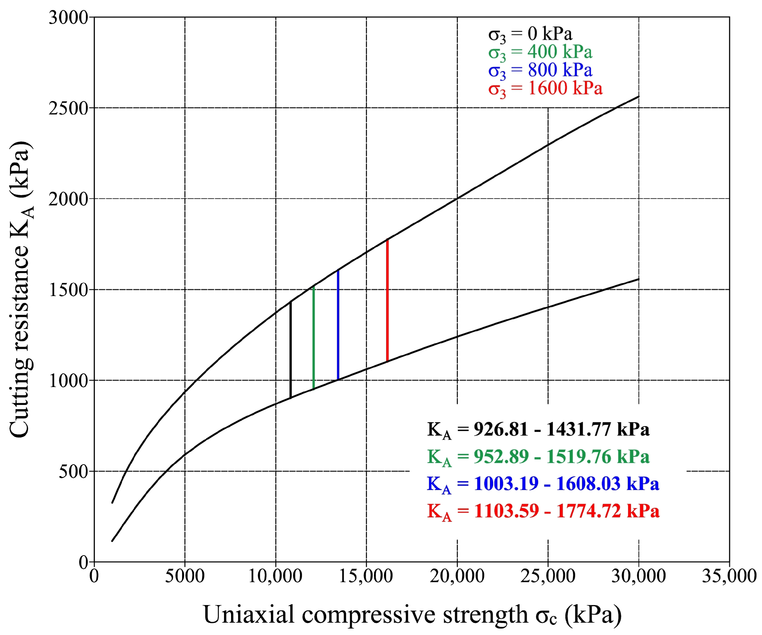
The uniaxial compressive strength, σc [23], has no direct relationship to the cutting resistance required by excavation machines. It is only possible to empirically compare the test results with the values already available from experience. The Krupp Industrietechnick has related the uniaxial compressive strength, σc (kPa), to the cutting resistance per unit area of the slice, KA (kPa), based on experience with a large number of operating bucket-wheel excavators and uniaxial compressive strength test results of rock samples excavated by these machines (Figure 6).
To calculate the cutting resistance of the excavator, values for rock material strength index proposed by Protodjakonow [1,14] were used. Rock material strength index, fpr, proposed by Protodjakonow is determined by the uniaxial compressive strength, σc (MPa), of the rock material, for which he gave the relationship:
fpr = σc/10 (MPa)
Protodjakonow classifies the rocks and soils into ten categories, as shown in Table 1. Bucket-wheel excavators can excavate the soil categories VI to X.
If only the uniaxial compressive strength, σc, data are available, the following empirical relationship to calculate the cutting resistance can be used:
KA = σc/10 = fpr (MPa)
This relationship is subjected to the large variations, and it can only be taken as a rough guide value.
5.2. Wedge Test Method
The cutting resistance of rocks is determined in the laboratory [1]. For this purpose, undisturbed material samples of cylindrical or cubical shape are used. The tested rock sample must have a length equal to the diameter or the base length. On the other hand, the testing wedge that is used for wedging the rock specimens has a wedge angle of 35° with a blunter tip of width b = 5 mm and length of l = 65 mm (Figure 7 and Figure 8) [14,17].
This test method suggests that the rock sample is installed into a suitable hydraulic press, used to apply the vertical force to the wedge. The vertical force constantly increases until the sample splits. During the tests and determining the value of the force which led to the sample splitting, the size of the wedge penetration into the specimen is recorded [24].
Cutting resistance per unit of cutting-edge length engaged, KL, and cutting resistance per unit of slice cross-sectional area, KA, are calculated according to the following equations [14]:
where: P—force (N), L—length of the specimen (cm’), and A—specimens’ cross-section area (cm2).
KL = P/L (N/cm′)
KA = P/A (N/cm2)
6. Modified Methodology of Cutting Resistance Testing for Underwater Coal Mining
The cutting resistance testing methodology for underwater coal mining is designed to determine changes in the value of cutting resistance depending on the change in the mining depth, which is represented by the change of hydrostatic (confining) pressure. The suggested laboratory test methodology is proposed so that different values of hydrostatic (confining) pressure can be provided during the tests. As mentioned before, the basic methodology for determining the cutting resistance includes two laboratory tests: uniaxial compressive strength tests and the wedge test method. This means that the modified methodology provides tests that can be used to report the compressive strength test and the wedge test for different values of confining pressure. The stated testing method is also known as the triaxial test, while the modification of the primary method was performed to determine the cutting resistance by the wedge method for different values of confining pressure.
The values of water hydrostatic (confining) pressure for which it is necessary to carry out cutting resistance tests are determined according to the equation:
where: γw—water unit weight, γ = 10 (kN/m3), and h—mining depth, h = 25–60 (m).
P = γw × h = 10 × (25–60) = 250–600 (kPa)
The pressure interval for the cutting resistance test is set according to the depths at which coal mining is performed (25–60 m), and it ranges from Pmin = 250 kPa to Pmax = 600 kPa.
During the tests, it was necessary to provide a water (confining) pressure, P (P = σ3), which exists at the coal mining depth (h = 25–60 m), and accordingly, the confining pressures during testing were P = σ3 = 250–600 kPa. Given that the coal mining is performed in hydrostatic pressure conditions at a certain depth in the water, values of the principal stresses are equal, and their values are σ1 = σ2 = σ3 = P = 250–600 kPa.
The cutting resistance testing program is carried out on the core samples (triaxial tests) and block-shaped rock material samples (modified wedge test method). The results of the laboratory triaxial test allow empirical comparison with the values already available from experience.
6.1. Triaxial Compression Test (Triaxial Test) Method
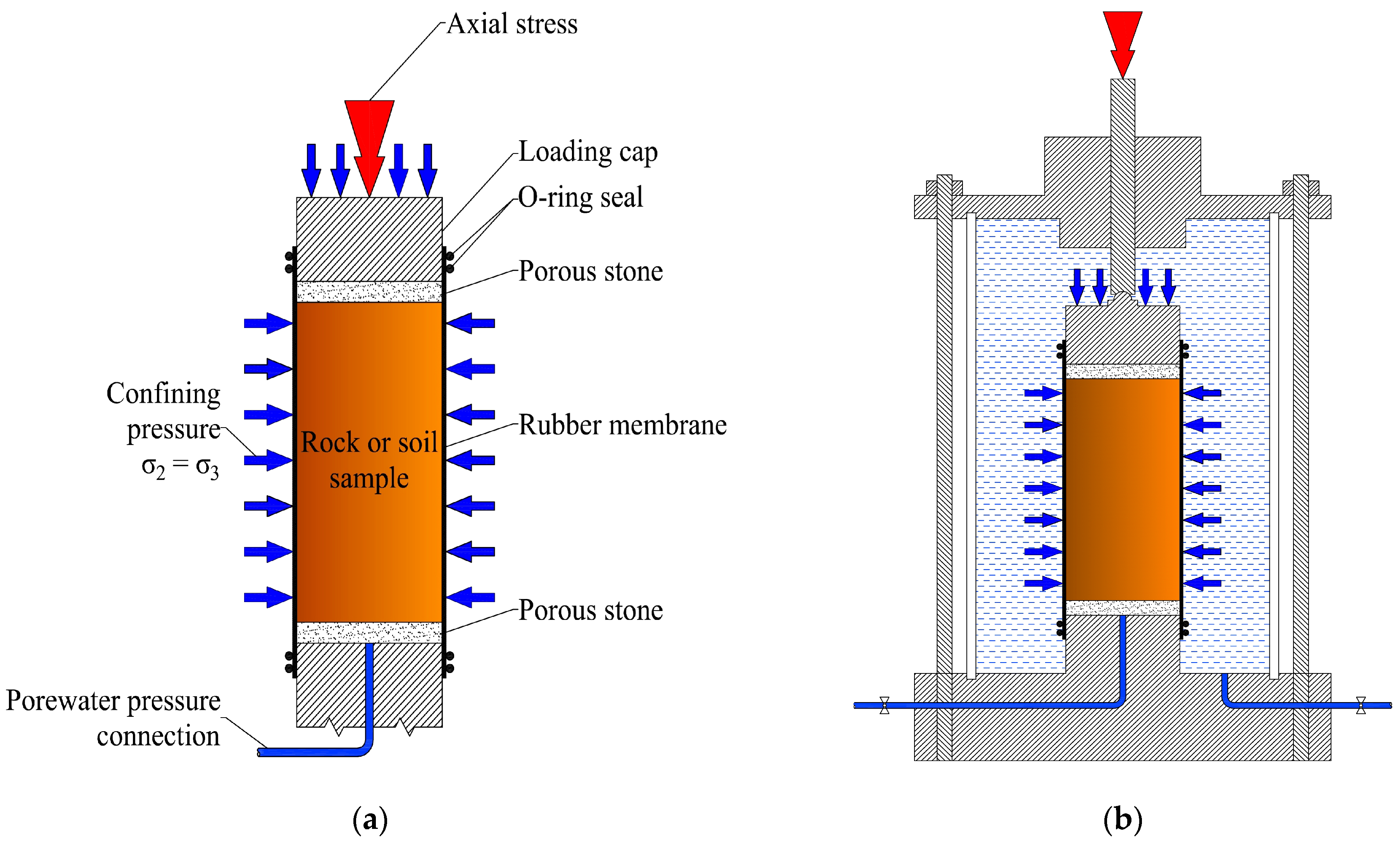
The triaxial compressive strength is determined on undisturbed rock, or soil material samples, of cylindrical shape [25], typically 38 mm or more in diameter and height equal to twice the diameter of the sample. A rock or soil sample is placed in a triaxial (glass or plastic) cell, in the triaxial test, with the sample being enclosed in a rubber membrane. The membrane is sealed to circular plates at the top and the bottom of the sample, with two o-ring seals ensuring a water-tight connection [26]. The cell is filled with water, with the pressure in the water being controlled by a pressure unit. The sample is subjected to an equal all-around pressure, known as the confining pressure, σ3. The sample is entirely surrounded by water, at its cylindrical surface and at the top, leading to a pressure equal to the cell pressure being generated in the sample [27]. The test procedure is to keep the confining pressure constant during the test. Triaxial apparatus features are shown in Figure 9 [28].
The sample is also being loaded by a vertical force, by using a steel rod that passes through the top cap of the cell. In the second stage of the test, the rod gets pushed down, at a constant rate, by an electric motor. Consequently, the vertical deformation rate is constant, and the force on the sample gradually increases. The force is measured using a strain gauge or a compression ring, and the vertical movement of the top of the sample is measured by a mechanical or an electronic measuring device. However, the vertical force on the sample will also gradually increase, but after some time, this reaches a maximum, and remains constant afterwards, or shows some small additional decreases, somewhat. The maximum of the vertical force indicates that the sample starts to fail. Usually, the test is continued up to a level where it is pretty clear that the sample has failed, by recording large deformations, up to 5% or 10% [29].
6.2. Modified Wedge Test Method
Cutting resistance tests for the underwater coal mining purpose were performed with the modified wedge testing method (Orenstein and Koppel), which allows the same “in situ” conditions that exist in the process of the coal mining in this deposit. The influence of water and mining depth is defined in terms of external loads so that the surrounding (confining) pressure value is constant and that it acts uniformly in all directions (Figure 10).
Cutting resistance tests for underwater coal mining conditions were carried out by using the equipment for triaxial testing of larger soil samples that was modified to meet designed test conditions. The main task of triaxial cell is to provide a confining pressure and maintain this pressure constant during the entire course of the tests (σ3 = const) (Figure 11). The same pressure conditions are required for performing the cutting resistance test in defined terms. On the other hand, standard triaxial cell for larger samples with maximum sample diameter of d = 150 mm is additionally equipped with the wedge for cutting resistance testing according to the wedge test method proposed by the company Orenstein and Koppel (Figure 7). The appearance of modified testing equipment is shown in Figure 12.
Similarly, cutting resistance tests in underwater coal mining conditions were carried out on prismatic specimens, which height was h = 100 mm, width a = 100 mm, and length b = 100 mm (diagonal of the base specimen was about 141 mm) (Figure 13 and Figure 14), which are placed at the center of the triaxial cell base. During the test, the sample was not isolated with rubber membrane, because the material (coal) in natural conditions is also directly exposed to the water pressure at a certain depth. After installation of sample and triaxial cell closure, the cell is filled with water, with the pressure in the water being controlled by a pressure unit, and the sample is subjected to an equal confining pressure. The test procedure is to keep the confining pressure constant during the test.
Additionally, the wedge is also loaded by a vertical force by using a steel rod that passes through the top cap of the cell. In the second stage of the test, the rod gets pushed down, at a constant rate, by an electric motor, and the vertical deformation rate is constant so that the wedge force on the sample gradually increases. The force is therefore measured using a strain gauge or a compression ring, and the vertical movement of the wedge is measured by a mechanical or an electronic measuring device. The vertical wedge force on the sample will also gradually increase, but after some time, this reaches a maximum and shows some small additional decreases, somewhat. The maximum of the vertical force indicates that the sample starts to fail.
7. Test Results
7.1. Triaxial Compression Test (Triaxial Test) Method
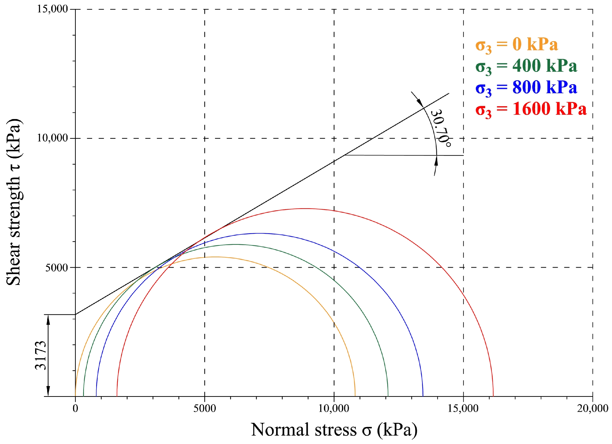
The triaxial compressive strength is determined on coal samples of cylindrical shape, with 38 mm in diameter and 76 mm in height. The samples were subjected to the confining pressure equal to σ3 = 400, 800, and 1600 kPa. A vertical force loaded the samples, and the vertical deformation rate was constant. The vertical force is measured using a compression ring, and the vertical movement of the top of the sample is measured by a mechanical measuring device. The maximum of the vertical force was recorded when the samples started to fail. The results of the triaxial test for each confining pressure are shown in Figure 15 and Figure 16 [30].
7.2. Modified Wedge Test Method
Cutting resistance tests in underwater mining conditions were carried out on prismatic specimens, dimensions 100 × 100 × 100 mm, which are placed at the center of the triaxial cell base [30]. During the test, the specimen was not isolated with rubber membrane, because the material (coal) in natural conditions is also exposed to the water at a certain depth. After installing the specimen and triaxial cell closure, the cell was loaded with distilled water, and then the load application was carried out in two phases. In the first stage, surrounding lateral load, σ3, was applied and it was kept constant during the entire course of the test (σ3 = const). In the second phase, the axial load, σ1, was gradually increased until fracture occurs. The sample before and after testing is shown in Figure 17.
The presented modified cutting resistance testing procedure in underwater coal mining conditions was used for tests in the water environment with a gradual increase of hydrostatic (confining) pressure, which regarding confining pressure was σ3 = 250, 300, 350, 400, 450, 500, 550, and 600 kPa. Results of modified wedge tests are shown in Table 2 and Figure 18.
8. Discussion
This section discusses the possibility of approximation of cutting resistance per unit area of the slice, KA (kPa), based on the Krupp Industrietechnick relationship for the uniaxial compressive strength, σc (kPa). Maximum axial stress, σ1, for each value of confining pressure, σ3 (σ3 = 400, 800, 1600 kPa) (Table 3), was used to approximate the cutting resistance per unit area of the slice, KA (kPa), according to the diagram shown in Figure 6. The values of cutting resistance, KA (kPa), based on axial stress, σ1, for each value of confining pressure, σ3, are presented in the diagrams shown in Figure 19 and Figure 20.
The rough guide value of cutting resistance per unit area of the slice, KA (kPa), is also calculated based on maximum axial stress, σ1, for each value of confining pressure, σ3 (σ3 = 400, 800, 1600 kPa) (Table 3), according to the empirical relationship KA = σ1/10 and rock material strength index proposed by Protodjakonow.
Analyzing the results of the modified wedge test, shown in Table 2, a linear functional dependence of the cutting resistance values and confining pressure, σ3, of the following form is observed:
KA = m × σ3 + n
By approximating the modified wedge test results, the linear functional dependences between cutting resistance and confining pressure, σ3, were determined, which are shown in Figure 21.
The values of linear functional dependence parameters, m and n, are shown in Table 4. The high value of the coefficient of determination, r2, and the Pearson’s correlation coefficient, r, was determined by approximating the cutting resistance test results with a linear function (Table 4). The values of Pearson’s coefficient, r, indicate a significant correlation between the values of the measured cutting resistance and the testing conditions (confining pressure, σ3) for which the tests were performed. However, considering the significant coefficient of variation (and over 20%), this functional dependence needs to be confirmed only by a quantitative increase in the number of tests when planning future research in this area.
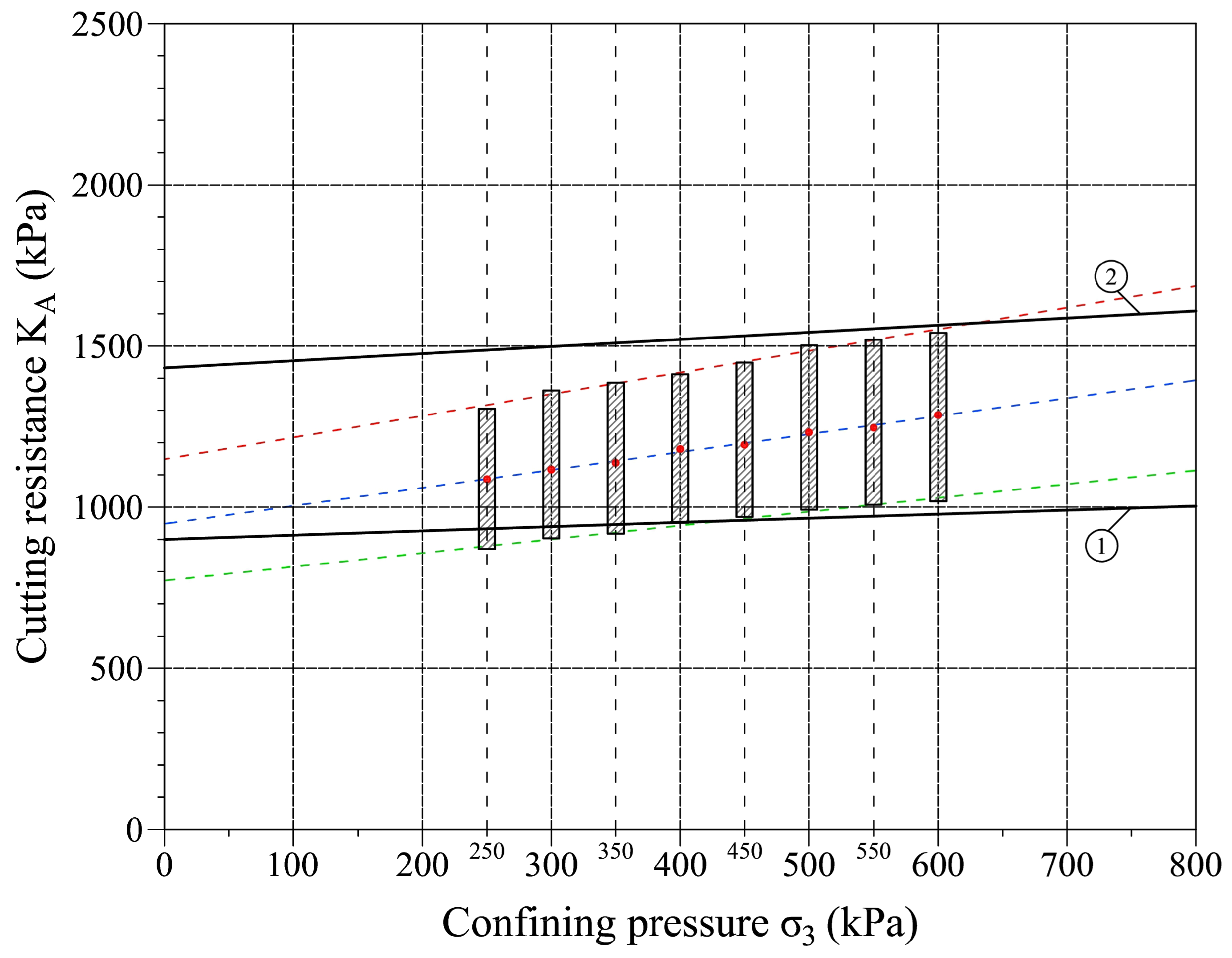
Empirical cutting resistance values based on the Krupp Industrietechnick empirical relationship and the results of the modified wedge test were then compared. A comparative presentation of the cutting resistance test results and empirically determined values is provided for the interval of confining pressure values, σ3, from 0 to 800 kPa (Figure 22).
Based on the comparison shown in Figure 22, it is clear that the confining pressure, σ3, interval, for which the digging resistance values were tested, largely corresponds with the values of this quantity determined on the basis of the empirical diagram. According to the presented results, the empirical evaluation for the values of confining pressure, σ3, from 0 to 400 kPa, shows higher values with the cutting resistance determined by the tests. For confining pressure, σ3, from 400 to 600 kPa, the test results and empirically determined values coincide. In comparison, for confining pressure, σ3, values above 600 kPa, the cutting resistance estimated on the linear approximation of test results show higher values compared to the empirically determined ones.
9. Conclusions
The bucket-wheel dredge “Kovin I” with bucket wheel UCW-450 rehabilitation involved an appropriate laboratory research program emphasizing the cutting resistance testing in underwater mining conditions. Coal mining working conditions at certain depths were simulated by a gradual increase of the confining pressure during the test. According to depths at which coal mining is performed during the testing, confining pressures of σ3 = 0, 250, 300, 350, 400, 450, 500, 550, and 600 kPa were applied.
The modified cutting resistance testing methodology for underwater coal mining is designed to determine changes in the value of cutting resistance depending on the change in the mining depth, which is represented by the change of hydrostatic (confining) pressure. The suggested laboratory test methodology is proposed to provide different values of hydrostatic (confining) pressure during the tests. The modified methodology for determining the cutting resistance includes two laboratory tests: the triaxial compressive strength test and the modified wedge test. Cutting resistance tests were carried out by using the equipment for triaxial testing of soil modified for these purposes. With modified testing equipment and the depicted method, it is possible to provide the water pressures which exist at a certain coal mining depth, so that the results of cutting resistance tests can be considered authentic.
The comparative analyses of cutting resistance laboratory testing methodologies were performed to evaluate the applicability of modified testing methodology to determine cutting resistance for underwater coal mining conditions and the influence of different confining pressure on the final value of coal cutting resistance. Presented results of the modified wedge test indicate a linear functional dependence of the cutting resistance values and confining pressure, σ3, with the values of Pearson’s coefficient (r) that indicate a significant correlation between the values of the measured cutting resistance and the testing conditions (confining pressure, σ3).
Empirical cutting resistance values based on the Krupp Industrietechnick empirical relationship and the results of the modified wedge test were then compared. Based on the comparative analysis of the cutting resistance test results and empirically determined values, the results of the modified wedge test largely correspond with the values of cutting resistance determined on the basis of the empirical diagram. According to the presented results of laboratory tests and comparative analysis, the suggested methodology of cutting resistance testing for underwater coal mining is a reliable basis for determining the necessary data for bucket-wheel dredge rehabilitation.
Author Contributions
Conceptualization, V.Č.; Methodology, V.Č.; Validation, V.R., S.Đ., and F.M.; Formal analysis, V.R.; Investigation, V.Č. and V.R.; Resources, V.Č. and V.R.; Data curation, V.R., S.Đ., and F.M.; Writing—original draft preparation, V.Č.; Writing—review and editing, V.R.; Visualization, S.Đ. and F.M. All authors have read and agreed to the published version of the manuscript.
Funding
This research received no external funding.
Conflicts of Interest
The authors declare no conflict of interest.
References
- Rasper, L. The Bucket Wheel Excavator; Trans Tech Publications: Clausthal, Germany, 1975. [Google Scholar]
- Golosinski, T.; Singhal, R. Basic considerations in selection of bucketwheel excavators. Int. J. Surf. Mining Reclam. Environ. 1987, 1, 67–72. [Google Scholar] [CrossRef]
- Khorzoughi, M.B.; Hall, R. A Study of Digging Productivity of an Electric Rope Shovel for Different Operators. Minerals 2016, 6, 48. [Google Scholar] [CrossRef]
- Vîlceanu, F.; Iancu, C. Bucket wheel rehabilitation of ERC 1400-30/7 high-capacity excavators from lignite quarries. IOP Conf. Ser. Mater. Sci. Eng. 2016, 161, 012081. [Google Scholar] [CrossRef] [Green Version]
- Mine Planning and Equipment Selection. Mine Plan. Equip. Sel. 2014, 303–310. [CrossRef]
- Jovančić, P.; Ignjatović, D.; Novaković, D. Optimisation of Coal Cutting Bits on Bucket Wheel Excavators. In Proceedings of the 5th Internationl Conference COAL 2011, Zlatibor, Serbia, 19–22 October 2011; pp. 124–138. [Google Scholar]
- Ignjatović, D.; Jovančić, P. Machines and Equipment for Surface Mining and Transport; Faculty of Mining and Geology, University of Belgrade: Belgrade, Serbia, 2012. [Google Scholar]
- Golubović, Z.; Lekić, Z.; Jović, S. Influence of bucket wheel vertical vibration on bucket-wheel excavator (bwe) digging force. Teh. Vjesn. 2012, 4, 807–812. [Google Scholar]
- Garbotz, G. Maschinenwesen Beim Baubetrieb III/1; Springer: Berlin, Germany, 1937. [Google Scholar]
- Wagon, H. Beitrag zur Frage der Anwendbarkeit von Schaufelradbaggern im Braunkohlenbergbau; Verlag Wilh. Knapp: Halle, Germany, 1939. [Google Scholar]
- Kienast, F. Die Gewinnung und Bewegung des Fordergutes an Abraumbaggern im Braunkohlenbergbau; Verlag Wilh. Knapp: Halle, Germany, 1937. [Google Scholar]
- Rasper, L. Die Enteicklung der Schaufelradbagger in Deutschland; Braunkohle, Wärme und Energie: Düsseldorf, Germany, 1955; Volume 7, pp. 430–441. [Google Scholar]
- Pajer, G. Drei Aufgaben aus der Theorie des Schaufelrades. Wissensch. Z. Hochsch. Schwermaschinenbau 1960, 4, 271–277. [Google Scholar]
- Durst, W.; Vogt, W. Bucket Wheel Excavator; Trans Tech Publications: Stafa-Zurich, Switzerland, 1988. [Google Scholar]
- Himmel, W. Der spezificsche Grabwiderstand in Abhangigkeit von der Spanflache und Spanform bei verschiedenen Bodenarten. Feriberger Foschungshefte 1963, A, 5–37. [Google Scholar]
- Marcelli, V.; Janicek, J. Research on Bucket Wheel Excavators; Czech Technical University: Prague, Czechoslovak Republic, 1956. [Google Scholar]
- Raaz, V. Assessment of the Digging Force and Optimum Selection of the Mechanical and Operational Parameters of Bucket Wheel Excavators for Mining of Overburden, Coal and Partings; Krupp Fördertechnik GmbH: Essen, Germany, 2002. [Google Scholar]
- Kolonja, B.; Torbica, S.; Ignjatović, D.; Stevanović, D.; Hamović, J.; Jovanović, M. Main Mining Project of Coal and Overburden Exploitation at the Underwater Mine ‘Kovin’ in the Undefended Part of the Field ‘A’; Faculty of Mining and Geology, University of Belgrade: Belgrade, Serbia, 2009. [Google Scholar]
- “Bager-1”. Available online: http://www.priv.rs/Ministarstvo-privrede/90/RUDNIK-KOVIN-AD.shtml/companyid=21858 (accessed on 26 April 2021).
- Marijanac, S.; Makar, N.; Jovanovic, B.; Stjepanovic, P. Maintaining the functionality of the coal settling basin at the underwater pit Kovin. Min. Met. Eng. Bor 2016, 1, 95–102. [Google Scholar] [CrossRef] [Green Version]
- Zivotic, D.; Cvetković, O.; Vulić, P.; Gržetić, I.; Simić, V.; Ilijevic, K.; Dojčinović, B.; Erić, S.; Radić, B.; Stojadinović, S.; et al. Distribution of major and trace elements in the Kovin lignite (Serbia). Geol. Croat. 2019, 72, 51–79. [Google Scholar] [CrossRef]
- Mitrović, D.; Đoković, N.; Zivotic, D.; Bechtel, A.; Šajnović, A.; Stojanović, K. Petrographical and organic geochemical study of the Kovin lignite deposit, Serbia. Int. J. Coal Geol. 2016, 168, 80–107. [Google Scholar] [CrossRef]
- ISRM. Suggested Method for Determining the Uniaxial Compressive Strength and Deformability of Rock Materials; International Society for Rock Mechanics and Rock Engineering: Lisbon, Portugal, 1979. [Google Scholar]
- Radojević, J. Rock Mechanics; University of Belgrade—Faculty of Mining and Geology: Beograd, Serbia, 1992. [Google Scholar]
- Braja, D. Principles of Geotechnical Engineering; CENGAGE: Boston, MA, USA, 2020. [Google Scholar]
- SRPS. EN ISO 17892-8:2018, Geotechnical Investigation and Testing—Laboratory Testing of Soil—Part. 8: Unconsolidated Undrained Triaxial Test; Institute for Standardization of Serbia: Beograd, Serbia, 2018. [Google Scholar]
- Ishibashi, I.; Hemanta, H. Soil Mechanics Fundamentals and Applications; CRC Press: Boca Raton, FL, USA, 2015. [Google Scholar]
- Verruijt, A. Soil Mechanics; Delft University of Technology: Delft, The Netherlands, 2010. [Google Scholar]
- Terzaghi, K.; Peck, R.B.; Mesri, G. Soil Mechanics in Engineering Practice; John Wiley & Sons, Inc.: Hoboken, NY, USA, 1996. [Google Scholar]
- Gojković, N.; Čebašek, V.; Obradović, R. Defining Geomechanical Parameters as a Function of the Exploitation Technological Process. at the Kovin Mine—Geomechanical Research Report for Determining the Cutting Resistance of the Bucket Wheel Dredge Kovin I Cutting Wheel UCW-450; Faculty of Mining and Geology, University of Belgrade: Belgrade, Serbia, 2004. [Google Scholar]
Figure 1.
Digging force components (FT—tangential, FL—lateral, and FFT—forward thrust).

Figure 2.
Bucket-chain dredger “5630”.

Figure 3.
Bucket-wheel dredger “Kovin I” with bucket wheel type UCW-450 [19].
Figure 3.
Bucket-wheel dredger “Kovin I” with bucket wheel type UCW-450 [19].

Figure 4.
Coal and gravel deposit “Kovin” simplified geological profile.

Figure 5.
Schematic representation of the geological coal and gravel deposit, “Kovin”, with pressure changes with increasing depth.
Figure 5.
Schematic representation of the geological coal and gravel deposit, “Kovin”, with pressure changes with increasing depth.

Figure 6.
Relationship between cutting resistance, KA, and uniaxial compressive strength, σc, (1—lowest value of KA, 2—highest value of KA).
Figure 6.
Relationship between cutting resistance, KA, and uniaxial compressive strength, σc, (1—lowest value of KA, 2—highest value of KA).

Figure 7.
Wedge test method: (a) the wedge and (b) wedge position while testing cutting force.

Figure 8.
Wedge testing method (Orenstein and Koppel): (a) cylindrical (core) sample and (b) cubical sample.
Figure 8.
Wedge testing method (Orenstein and Koppel): (a) cylindrical (core) sample and (b) cubical sample.

Figure 9.
Triaxial test: (a) rock or soil sample in triaxial test and (b) triaxial cell with sample [25,28,29].

Figure 10.
The position of the wedge in the modified wedge test method.

Figure 11.
The basic principle and equipment for larger samples’ (d = 150 mm) triaxial test performance.
Figure 11.
The basic principle and equipment for larger samples’ (d = 150 mm) triaxial test performance.

Figure 12.
The modification of triaxial test equipment for underwater coal mining cutting resistance testing.
Figure 12.
The modification of triaxial test equipment for underwater coal mining cutting resistance testing.

Figure 13.
Basic equipment parts for underwater coal mining cutting resistance testing.

Figure 14.
Modified triaxial test equipment for underwater coal mining cutting resistance testing: (a) modified triaxial test equipment, (b) testing wedge position.
Figure 14.
Modified triaxial test equipment for underwater coal mining cutting resistance testing: (a) modified triaxial test equipment, (b) testing wedge position.

Figure 15.
Results of triaxial compression tests of coal.

Figure 16.
Shear strength of coal.

Figure 17.
Sample for cutting resistance testing in underwater coal mining conditions (a) before testing and (b) after testing.
Figure 17.
Sample for cutting resistance testing in underwater coal mining conditions (a) before testing and (b) after testing.

Figure 18.
Cutting resistance test results’ intervals for all defined confining pressures, σ3.

Figure 19.
Relationship between cutting resistance, KA, and vertical stress, σ1.

Figure 20.
Relationship between cutting resistance, KA, and confining stress, σ3 (σ3 = 400, 800, 1600 kPa) (1—lowest value of KA, 2—highest value of KA, 3—empirical relationship KA = σ1/10).
Figure 20.
Relationship between cutting resistance, KA, and confining stress, σ3 (σ3 = 400, 800, 1600 kPa) (1—lowest value of KA, 2—highest value of KA, 3—empirical relationship KA = σ1/10).

Figure 21.
Linear approximation of the modified wedge test results.

Figure 22.
Comparison of the results of the modified wedge test and empirical cutting resistance values (1—lowest value of KA, 2—highest value of KA).
Figure 22.
Comparison of the results of the modified wedge test and empirical cutting resistance values (1—lowest value of KA, 2—highest value of KA).


Table 1.
Protodjakonow classification of the rocks and soils [14].
Table 1.
Protodjakonow classification of the rocks and soils [14].
| Class | Strength of Rock/Soil | Type of Rock/Soil | Strength Index, fpr (MPa) | Uniaxial Compressive Strength, σc (MPa) |
|---|---|---|---|---|
| I | High-strength rocks | Solid and tough quartz and basalt | 20 | 200 |
| II | Very hard rocks | Porphyritic quartz, granite | 15 | 150 |
| III | Hard rocks | Granite, hard sandstone, hard iron ore | 10 | 100 |
| IV | Relatively hard rocks | Normal sandstone, iron ore | 6 | 60 |
| V | Medium hard rocks | Hard clay slate, soft sandstone, and limestone | 4 | 40 |
| VI | Relatively soft rocks | Soft slate, very soft sandstone, chalk, fine sand, anthracite, cemented pebble stones, and sand | 2 | 20 |
| VIa | Relatively soft stones | Gravel soil, broken slate, hard fossil coal, hardened clay | 1.5 | 15 |
| VII | Soft stone | Hard clay, soft fossil coal, clayey soil, hard brown coal | 1.0 | 10 |
| VIIa | Soft stone | Gritty clay, coarse clay, loess | 0.8 | - |
| VIII | Soils | Top soil, peat, loam, sand | 0.6 | - |
| IX | Loose soils | Sand, dumped soils, soft brown coal | 0.5 | - |
| X | Muddy soils | Mud, muddy loess | 0.3 | - |
Table 2.
Results of cutting resistance tests for all defined confining pressures, σ3.
| Confining Pressure, σ3 (kPa) | Cutting Resistance, KA (kPa) | |||||
|---|---|---|---|---|---|---|
| Sample no. 1 | Sample no. 2 | Sample no. 3 | Average | Standard Deviation | Coefficient of Variation | |
| 250 | 933.76 | 1126.24 | 1438.58 | 1166.19 | 254.77 | 21.85 |
| 300 | 956.00 | 1142.83 | 1441.30 | 1180.04 | 244.78 | 20.74 |
| 350 | 976.05 | 1168.87 | 1466.77 | 1203.90 | 247.23 | 20.54 |
| 400 | 1007.05 | 1216.88 | 1505.15 | 1243.03 | 250.08 | 20.12 |
| 450 | 1019.48 | 1187.66 | 1538.85 | 1248.66 | 265.01 | 21.22 |
| 500 | 1048.27 | 1276.93 | 1559.32 | 1294.84 | 255.99 | 19.77 |
| 550 | 1065.94 | 1278.37 | 1588.83 | 1311.05 | 262.97 | 20.06 |
| 600 | 1063.48 | 1365.38 | 1642.38 | 1357.08 | 289.54 | 21.34 |
Table 3.
Results of cutting resistance tests for all defined confining pressures, σ3.
| Confining Pressure, σ3 (kPa) | Vertical Stress, σ1 (kPa) | Cutting Resistance, KA (kPa) | ||
|---|---|---|---|---|
| Lowest Value | Highest Value | KA = σ1/10 | ||
| 0 | 10,820 | 903.81 | 1431.77 | 1082 |
| 400 | 12,090 | 952.89 | 1519.76 | 1209 |
| 800 | 13,440 | 1003.19 | 1608.03 | 1344 |
| 1600 | 16,160 | 1103.59 | 1774.72 | 1616 |
Table 4.
Linear function parameters for approximation of the modified wedge test results.
| Confining Pressure, σ3 (kPa) | Linear Function Parameters | |||
|---|---|---|---|---|
| m | n | r2 | r | |
| Minimum | 0.5894 | 1272.10 | 0.9744 | 0.9871 |
| Maximum | 0.5404 | 1020.93 | 0.9799 | 0.9899 |
| Average | 0.4016 | 838.06 | 0.9722 | 0.9860 |
Publisher’s Note: MDPI stays neutral with regard to jurisdictional claims in published maps and institutional affiliations. |
© 2021 by the authors. Licensee MDPI, Basel, Switzerland. This article is an open access article distributed under the terms and conditions of the Creative Commons Attribution (CC BY) license (https://creativecommons.org/licenses/by/4.0/).
Share and Cite
MDPI and ACS Style
Čebašek, V.; Rupar, V.; Đenadić, S.; Miletić, F. Cutting Resistance Laboratory Testing Methodology for Underwater Coal Mining. Minerals 2021, 11, 564. https://0-doi-org.brum.beds.ac.uk/10.3390/min11060564
AMA Style
Čebašek V, Rupar V, Đenadić S, Miletić F. Cutting Resistance Laboratory Testing Methodology for Underwater Coal Mining. Minerals. 2021; 11(6):564. https://0-doi-org.brum.beds.ac.uk/10.3390/min11060564
Chicago/Turabian StyleČebašek, Vladimir, Veljko Rupar, Stevan Đenadić, and Filip Miletić. 2021. "Cutting Resistance Laboratory Testing Methodology for Underwater Coal Mining" Minerals 11, no. 6: 564. https://0-doi-org.brum.beds.ac.uk/10.3390/min11060564
Note that from the first issue of 2016, this journal uses article numbers instead of page numbers. See further details here.