
Instability Assessment of Hanging Wall Rocks during Underground Mining of Iron Ores


1
Belt and Road Initiative Institute for Chinese-European Studies (BRIICES), Guangdong University of Petrochemical Technology, Maoming 525000, China
2
Department of Mining Engineering and Education, Dnipro University of Technology, 49005 Dnipro, Ukraine
3
PJSC Zaporizhzhia Iron-Ore Plant, 69061 Zaporizhzhia, Ukraine
*
Author to whom correspondence should be addressed.
Minerals 2021, 11(8), 858; https://0-doi-org.brum.beds.ac.uk/10.3390/min11080858
Submission received: 15 July 2021
/
Revised: 9 August 2021
/
Accepted: 9 August 2021
/
Published: 10 August 2021
(This article belongs to the Special Issue Exploring Mining Landscapes: Reconciling Past and Present of Mining Activity)
Abstract
:The paper presents the study of the deformation processes development in unstable rocks of the hanging wall during mining a thick steeply dipping ore deposit in the example of the Yuzhno-Belozerskyi deposit. In the studied field, there are problems of stability of hanging wall rocks, represented by low-resistant shale rocks that do not withstand significant outcrops in time. A decrease in stability is manifested in the form of failure of the hanging wall rocks into the stope. Based on a detailed study of the ore deposit geological structure and the performance of the stopes mining, according to the survey data, an area of the deposit has been identified where the ore failure and dilution reach 4%–8% with a maximum value of 12%. This also makes it possible to determine the most important averaged source data for performing physical modeling on equivalent materials. It has been determined that the deformation value of the hanging wall rocks with subsequent failure into the stope and ore mass deformation in the sloping bottom change exponentially with an increase in the depth of the stope location, and the dynamics of increasing rock deformations in the hanging wall is noticeably higher than in the sloping bottom of the stope. This reduces the quality of the mined ore and increases the probability of rock failure area propagation to the hanging wall drifts with their subsequent destruction. The results of physical modeling are characterised by acceptable reliability and are confirmed by a high similarity with the actual data on ore dilution with broken rocks during the stopes development. It has been found that during the formation of a steeply dipping outcrop of stopes with an area of 1200 m2, unstable rocks of the hanging wall are prone to failure of significant volumes. For successful mining and achieving stope element stability, it is recommended to optimise its parameters, the height, width and the value of a steeply dipping outcrop, as well as to preserve the ore pillar in the hanging wall until the ore is broken and drawn from the rest of the stope.
Keywords:
ore deposit; hanging wall; rocks; failure; low stability; deformations; dilution; physical modeling; equivalent materials; Ukraine1. Introduction
In underground mining, including iron ore mining, the issues of rock mass stability are always important, since the safety of workers, the quality of minerals and the preservation of the Earth’s surface depend on it. This is especially important for mining the valuable ores with chambers (stopes) of large sizes, when the stage-by-stage breaking of their reserves gradually increases the area of outcropping the hanging wall rocks and redistributes the stress-strain state, which requires direct attention in practice, and an assessment and prediction of stability should be undertaken.
The volumes of mineral resources produced are always regulated by the needs of the domestic and foreign markets [1,2,3]. The growing demand for mineral resources in the world markets necessitates constantly improving the methods of mining and processing of minerals to obtain vital raw materials and energy resources for mankind [4,5]. On the other hand, it is expected the social philosophy of a ‘unnecessary consumption’ and significantly reduce unnecessary costs will be abandoned, which could extend the life of the Earth’s mineral resources by several generations [6,7,8]. Enhanced ecological, as well as environmental factors, are taken into account when developing progressive technologies of minerals mining [9,10,11] and providing stability of geo-technological and geological structures [12,13,14,15].
Iron ore mining is of great economic and strategic importance for a number of countries such as Brazil, Australia, Russia, Ukraine, Canada, USA, India, China, South Africa, Iran [16,17,18,19,20]. More than 85% of the world’s iron ore reserves are concentrated in the lithotypes of these countries [21,22].
For developing countries such as Ukraine, the export of iron ore raw materials provides substantial foreign exchange earnings to the state budget and in 2020 amounted to 4.2 billion. The main consumers of Ukrainian iron ore raw materials (ore, pelletised ore, concentrate) are China (60%), Poland (8.9%), Czech Republic (7%), etc. About 160 million tons of iron ore are mined in Ukraine annually, of which 90% is mined by open-cut mining, and 10% by underground mining [23,24,25,26].
The main iron ore production is conducted by the companies PJSC ArcelorMittal Kryvyi Rih (2 mines and 1 quarry), Metinvest Holding (4 mines and 4 quarries), Development Construction Holding, DCH (2 mines) at the Kryvyi Rih Iron-ore Basin, where more than 70% of all reserves of Ukraine are concentrated. The iron content reaches an average of 57%. Iron ores with an average grade are mined at 2 large quarries of Ferrexpo iron ore company in the Kremenchuk iron ore region [27,28]. The Belozerskyii iron-ore region, where the PJSC Zaporizhzhia Iron Ore Plant develops rich iron ores of the Yuzhno-Belozerskyi and Pereverzivske deposits, is of significant industrial importance. This field is unique due to its high iron content in the range of 58%–67%, and more than 60% of the reserves are high-grade ores that do not require a beneficiation cycle [26,29].
When mining the raw iron ores, the problem of their quality is extremely important and has significant commercial relevance [30,31,32]. Ore quality fluctuations complicate its processing, thereby deteriorating the technological parameters of the beneficiation process [33,34]. This, in turn, leads to ineffective use of mineral raw materials, an increase in the cost of metallurgical treatment and, as a result, a decrease in the economic efficiency of the entire mining and metallurgical complex [35,36,37,38]. The downward trend in the mined iron ore quality is more characteristic of the underground mining method, which is conditioned by a greater depth of mining and an increase in intensity of the rock pressure manifestation with deepening. As a result of the impact of technological, as well as mining-and-geological factors during underground mining method, there are frequent cases of significant dilution of the ore mined from the stopes.
In the Kryvyi Rih Iron-ore Basin, iron ore is mined by a system of sublevel blast-hole stoping and sublevel caving mining method at an average uniaxial compression strength of 120–140 MPa of the hanging wall and foot wall rocks. In this case, the main reason for the ore dilution is the deviation in the blast-holes direction and their exit into the space beyond the contour, which leads to the waste rocks destruction beyond the extraction contour of the ore body, followed by dilution of the ore mass with them and a decrease in the Fe content to 12% [39,40].
In the conditions of the Yuzhno-Belozerskyi deposit, high-grade ores are mined by a highly efficient system of sublevel blast-hole stoping with uncemented rockfill under conditions of variable strength 60–150 MPa of hanging wall rocks. The main reason for an increase in indicators of the broken ore dilution in a number of primary stopes from 5% to 10%–12% is the failure of the hanging wall rocks caused by geomechanical processes [41,42]. When mining the secondary stopes, dilution occurs mainly from the filling mass failure [43]. In the conditions of the studied field, with a steady decline in the quality of mined hematite-martite ores, it is necessary to apply an expensive cycle of additional beneficiation of ores.
Analysis of the causes of ore dilution at various fields leads to conclusion that the most difficult task is to predict, control and prevent the cases of hanging wall rocks failure as a result of natural and technogeneous influence, as opposed to controlling the blast-holes direction by introducing the special automated systems. Unstable rocks in the hanging wall adversely affect the efficiency and safety of ore mining in the mine as a whole [44]. As a result of the hanging wall rocks failure into the stope, the volume of underground cavities that must be filled with the filling mixture increases, thereby leading to additional costs. The development of large-scale failures of hanging wall rocks is rather dangerous from the point of view of safety, since sublevel drifts are driven at a distance of 20–25 m from the ore deposit contour, along which people, equipment and materials move. Rock failures can severely damage sublevel drifts and pose a hazard to workers. Also, broken-down rocks with an iron content of 25%–30% significantly dilute the broken ore, reducing the total iron content in the ore for extraction stope. This leads to the necessity of mixing the mined ore from different stopes to provide the overall mine quality of the ore [45].
A large number of studies have been devoted to the problematic issues of the hanging wall rocks’ stability and the dilution of ores as a result of their failure with the use of numerical simulation. The stability of hanging wall rocks with a change in the angle of the ore deposit slope, as well as the height and width of extraction stope have been studied. In addition, the optimal parameters have been determined, at which the dilution of the ore with hanging wall rocks is less [46,47,48]. The state of hanging wall rocks in a low-thickness deposit has been studied, where the authors conclude that their unstable state is caused by the fracturing and strength of rocks, their constriction and an increase in the relaxation zone. Authors recommend leaving a layer of ore to support the rocks in the hanging wall [49]. Attention is focused on the geomechanical and economic substantiation of the ore layer thickness to prevent the failure of the hanging wall rocks [50]. To predict the depth of the hanging wall rocks destruction, the authors use the Evolutionary random forest (ERF) method, where the algorithm has revealed high convergence with the actual data of the mine [51]. A new criterion for assessing the stability of the hanging wall rocks has been developed, which testifies to a significant influence and interdependence between the rocks quality and the principle of the load formation on the overlap of the hanging wall rocks [52]. A number of other studies are also known to be related to the stability of hanging wall and foot wall rocks that come into contact with extraction stope in the process of ore mining [53,54,55,56].
Noteworthy research has been conducted in which problematic issues of defining deformation zones of the rock mass, ensuring the stability of mine workings using numerical modeling methods are solved [57,58]. The choice of failure criteria in the numerical analysis of stability plays an important role in determining the stability of underground workings. The failure criterion will only be useful if it is selected based on the correct failure mechanism [59,60]. The accuracy of the study of numerical modeling will depend on the correct choice of the deformation criterion, the adequate formulation of the problem and the quality of the initial data [61,62].
However, the deformations of the hanging wall rocks during the mining of steeply dipping thick ore deposits, where, depending on the thickness of the deposit, 2–3 extraction stopes are located across the strike, taking into account the order of mining the reserves, have not been sufficiently studied in the literature. To develop technical solutions for reducing the ore dilution, it is necessary, first of all, to have an idea of the mechanism and volumes of the rocks failure in the hanging wall.
This paper studies the deformation processes development in the hanging wall rocks during the mining of thick ore deposit at the Yuzhno-Belozerskyi field, the most valuable in terms of iron ore content in Ukraine.
2. Geology and Characteristics of the Existing Technology for Iron Ore Mining
The Yuzhno-Belozerskyi field occupies the northern part of the Central Syncline western flank and is a strip of submeridional strike (from northwestern to northeastern) of ferruginous quartzites containing high-grade iron ores. The ore-bearing horizon of ferruginous quartzites is concave to the west. Its strike changes on the southern flank—northwestern (310°), further—submeridional, and then (to the north from the survey profile 39)—northeastern (40°). The slope angle of the ore deposit increases from south to north—from 60–65° to 80–85°. The iron content in the ores of the Belozerskyi region ranges from the side (48%) to 69% for the Yuzhno-Belozerskyi field. The Yuzhno-Belozerskyi field is represented by the Glavnaya deposit. The deposit has a complex sheet-like shape, extending to the dip to an elevation of 1500 m. Along the strike, the ore deposit area decreases with depth. At 325–400 m level, the deposit extends 2200 m, but at 740–840 m level this value is already 1500 m. The iron ore reserves of the field are 300 million tons, while 50% of the balance reserves have already been mined.
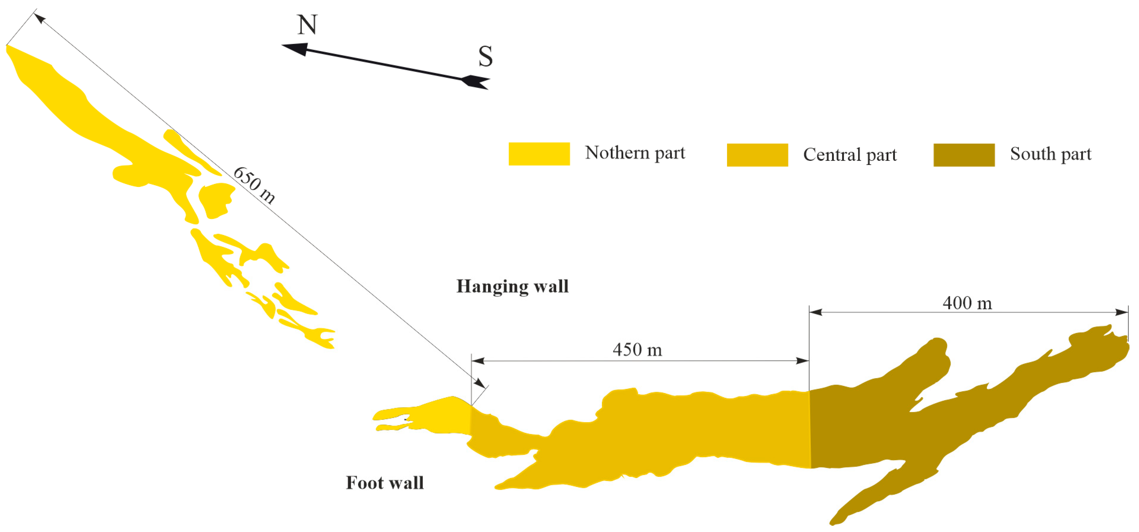
The geological conditions of the Glavnaya deposit are characterised by significant variability along the strike [63]. Based on a detailed study of geological plans and reports of geological survey along the strike of the ore deposit, it can be argued that there are characteristic zones of the ore deposit that have differences. The northern, central and southern parts of the deposit differ in the morphological composition of ores and host rocks, their strength, fracturing, the thickness of the deposit and its slope angle. A general view of the ore deposit longitudinal section at 740–840 m level with plotted various zones with similar mining-and-geological conditions is shown in Figure 1.
The northern part of the deposit differs noticeably in the shape of the ore bodies and the composition of the rocks. This zone extends for a length of 650 m. The deposit thickness here varies from 20 to 60 m. The average ore hardness according to Professor M.M. Protodyakonov scale [64,65] is f = 9.5. Ore deposit here is broken into several veins, they are separated by quartzite, mainly of hematite-martite composition, 7–20 m thick with a low iron content. The host rocks of the hanging wall and foot wall are predominantly hematite-martite quartzites of f = 14–15 hardness, medium stability and fracturing.
The central part of the deposit extends for 400 m. The ore body thickness here is sufficiently persistent and increases to 100–120 m, the average ore strength decreases and reaches f = 7.0. The hanging wall and foot wall contain quartzites f = 14–15, which, when approaching the southern part, are replaced by quartz-chlorite-sericite shales and quartz-hematite-chlorite composition with a hardness from f = 7–9 to f = 8–10, of medium stability and fracturing. There are interlayers of low-resistant talcose shales of sericite-chlorite composition with a hardness of f = 4–6.
The southern part of the deposit extends for 450 m. The deposit thickness here ranges from 60 to 150 m with the ore hardness of f = 6.5. The host rocks in the hanging wall and foot wall are quartz-chlorite-sericite and quartz-sericite-chlorite shales with a hardness from f = 7–9 to f = 8–10, of medium stability and high and medium fracturing. By analogy with the central part, there are interlayers of low-resistant talcose shales of sericite-chlorite composition with a hardness of f = 4–6.
The noted significant changes in the ore deposit geological structure also cause changes in the mining technology. Thus, for example, in the northern part of the field, due to the insignificant deposit thickness (30–50 m), one stope is located across the strike of the deposit thickness, and in the central and southern parts, where the thickness reaches more than 100 m, 2–3 stopes are located across the strike. When mining the last stopes, this leads to an increase in the number of contacts with the artificial mass, which causes dilution and deteriorates the quality of the mined ore.
For effective planning of mining operations development, the ore deposit of the Yuzhno-Belozerskyi field from the centre to the flanks is conventionally divided every other 30 m into surveying axes with the designations: n is north; 0 is centre; s is south, respectively. The stopes are also numbered in consecutive numbers, according to the surveying axis and the sequence of mining (for example, 1/7 s, 2/7 s). At present, the main mining operations are carried out within the interval of 640–940 m depths, the reserves of 640–740 m level have been mined-out, the reserves of 740–840 m level have been 75% mined-out, the reserves of the 840–940 m are at the initial stage of mining [66].
The ore is mined by a system of sublevel blast-hole stoping with the subsequent filling the mined-out area with an uncemented rockfill [67]. The ore breaking in the stope is sublevel, by vertical layers in one plane or in advance by upper sublevels, which is carried out on a pre-cut slot located across the stope by fan systems of upward wells and downward wells in the direction of the hanging wall. The wells are drilled by NKR-100M drilling rigs (d = 102 mm) and Simba H1352, Solo DL321 (d = 105 mm) self-propelled rigs from sublevel drill cross-cuts. Slots are cut into cutoff raising stopes by parallel upward and downward wells drilled from sublevel drill cross-cuts and cut ways using NKR-100M drilling rigs. Grammonite 79/21, AC-8, packaged ammonite No.6ZhV, UkrainitPP type are used as explosive materials to break the ore reserves in the stope. The drawing of ore from the stopes is performed using vibratory loading units of the VVDR-5 type.
The filling mixture is prepared from ground granulated blast-furnace slag, rock refuse, waste of flux limestone using the surface complex [68,69]. By using the rocks as a filling mixture component, it is possible to gradually reduce the dump volume [70]. The filling mass strength after 90 days of hardening is 6–9 MPa [71,72,73].
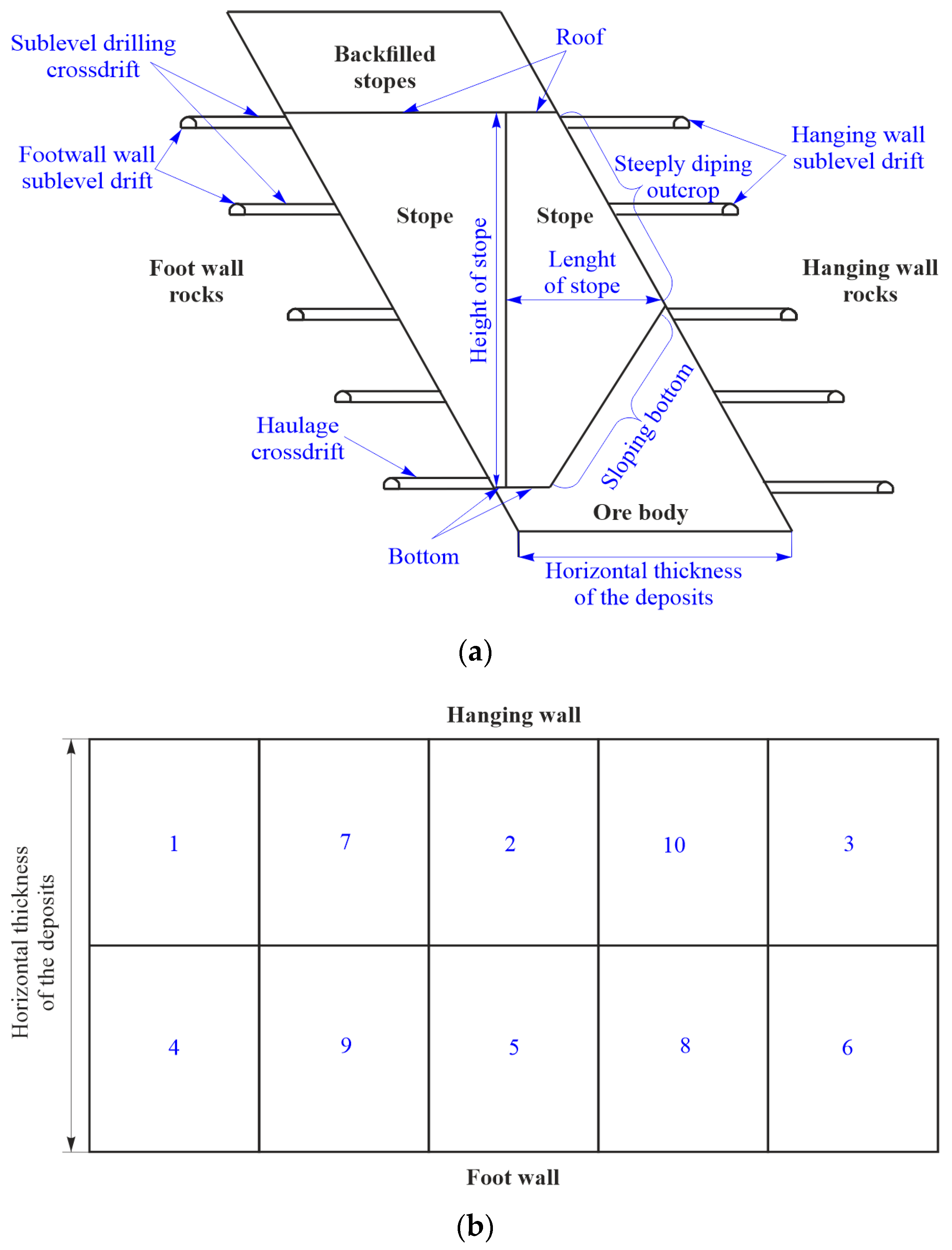
The stopes are mined through a pillar equal to the stope width and are located across the orebody strike. The technological elements of the system for mining the ore deposit with an illustration of all its elements, as well as the order of mining the extraction stopes along the ore area, are shown in Figure 2a,b.
The mined-out stopes at adjacent levels should always be located behind the general zones location influenced by the space of the mined-out stopes. The average parameters of the stopes are accepted: width is 30 m; length is 40–50 m; height is 100–120 m.
The main technical and economic indexes of the mine operation are: with an annual ore output of 4.5 million tons/year, 15–17 stopes are mined and laid. The average output of ore by stopes is 30,000 tons/month. The process of laying the stope is performed during 1–2 months, depending on its volume and location in the mine field. The average level of ore loss is 5%, dilution ranges from 5% to 10%.
When mining within the depth interval of 640–940 m in the central and southern zones of the deposit, problems arise of stability of the hanging wall rocks, represented by quartz-chlorite-sericite, sometimes talcose shales with a hardness of f = 4–9, which do not withstand significant outcrops in time. The decrease in stability is expressed in the form of the hanging wall rocks failure at the contact with the steeply dipping outcrop into the extraction stope. Sometimes the volume of failure has critical values, reaching the sublevel drifts in the hanging wall. The ore dilution with waste rocks at the contact with the hanging wall rocks in some stopes increases from the standard 5.0% to 12.0% [74,75].
To solve the problem of stability, it is necessary to study the deformation processes of the hanging wall rocks during the gradual mining of both the stope reserves and the stopes themselves in the direction from the foot wall to the hanging wall. An adequate and reliable assessment of the mass deformations can be obtained by modeling on equivalent materials. However, it is necessary to know which physical and mechanical properties of a changing ore deposit should be modelled, and which equivalent materials are used during modeling. This can be achieved by determining the tendency of changing intensity of the hanging wall rocks failure along the deposit strike. As a result, it will be possible to identify an area of a deposit with a low-resistant hanging wall and analyse the mining-geological and mining-technical conditions of mining here.
3. Materials and Methods
3.1. Determining the Unstable Zones in the Hanging Wall Rock Mass
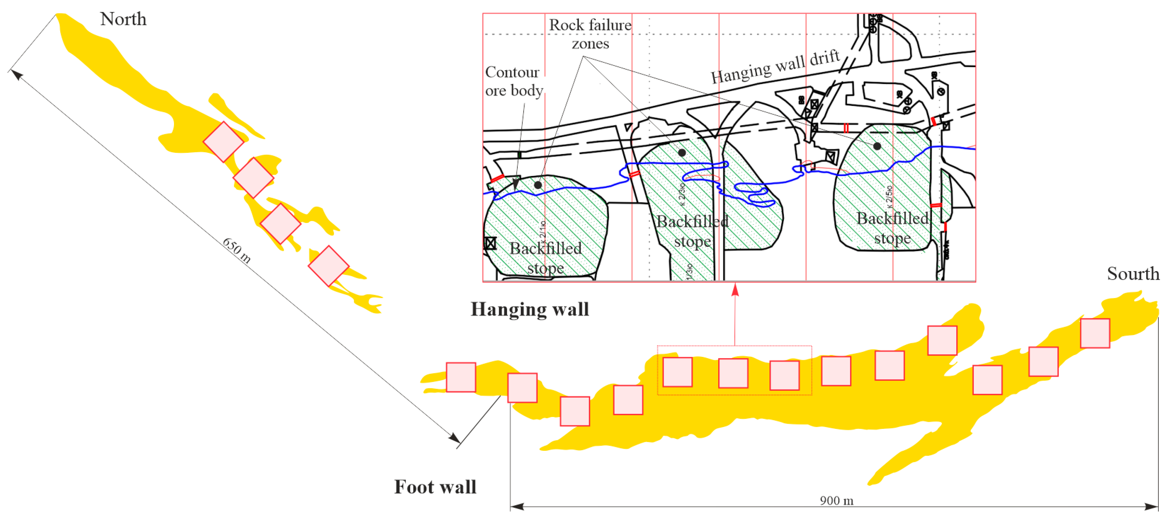
It is possible to reveal an area of the ore deposit with an increased intensity of the hanging wall rocks failure by reproducing the history of mining the extraction stopes at the contact with the hanging wall rocks. In the process of analysing and studying geological and mine surveying data, as well as mining plans, 17 extraction stopes have been allocated for research. The location of the studied extraction stopes along the ore deposit strike is shown in Figure 3.
The selected stopes, surrounded by the ore mass, are mined to eliminate dilution caused by the failure of filling mass and to focus only on the failure of hanging wall rocks. In the mined-out stopes, the index of the mined ore dilution and the size of the steeply dipping outcrop area of the stope at the contact with the rocks are studied. In addition, the facts of rocks failure into the stope space and the disturbances of the design contours of extraction stopes are also fixed.
By comparing the indices of ore dilution with waste rocks in stopes and their location along the ore deposit strike, it will be possible to determine a tendency of changing the volumes of hanging wall rocks failure and to identify their unstable zones in the deposit for subsequent physical modeling.
3.2. Physical Modeling on Models from Equivalent Materials
In order to adhere the similarity of the model to natural conditions [76,77], the studies allow for obtaining data on the stability of structural elements of mining systems with various shapes and sizes of mined-out spaces reproduced on the models. Modeling by the method of equivalent materials is as follows:
- the model of rocks and minerals is made from artificially selected materials in compliance with Newton’s similarity law;
- to achieve mechanical similarity, the model is made of materials with properties, equivalent to physical and mechanical properties of prototype materials. Such ratios are determined on the basis of general law of force similarity, taking into account the simultaneous action of gravity force and internal stress.
The geometric similarity of the model in situ will be fulfilled if all the dimensions of the space occupied by the studied system on the model, as well as its individual elements, are changed a certain number of times compared to the dimensions of the space occupied by a similar system in situ. Signs of geometric similarity are written in the form of a ratio of linear dimensions:
where αe is geometric scale of modeling; L is linear size of the modelled element in situ; l is linear dimension of the corresponding modelled element on the model.
To ensure the similarity of mechanical processes on the model, the mechanical characteristics in situ of the equivalent material must meet the requirements:
where Nm and Np are the mechanical characteristics of the model equivalent material and the prototype material, respectively; γm and γp are the volumetric weight of the model and prototype material, respectively.
Taking into account the signs of geometric similarity and mechanical processes similarity, as well as having data on the mechanical characteristics of the modelled rocks, expressed in numerical values, for a given scale of modeling, the numerical values of the corresponding characteristics of model material mechanical properties are calculated, which are necessary to ensure similarity. The modeling is conducted on a flat testing bench with a front transparent wall. Model dimensions: length 1.40 m, height 1.25 m, width 0.24 m.
To model the deposit mining, the averaged parameters of the ore deposit and the host rocks are taken, where the problems of the hanging wall rocks stability have been previously identified:
- deposit thickness—100 m;
- angle of the deposit slope is 70°;
- angle of the bottom slope in the hanging wall stope is 55°;
- stope height—115 m;
- hanging wall is represented by low-resistant talcose shales and quartz-chlorite-sericite shales;
- foot wall is represented by quartz-chlorite-sericite shales.
- To study the structural elements stability of mining system, a geometric modeling scale of 1:250 is accepted on the model, which makes it possible to measure deformations with a greater degree of accuracy.
Sand, solid oil, paraffin, talc and cement are selected as components of the equivalent material. This makes it possible to ensure the equality of the internal friction angles of materials, strength and other physical and mechanical properties of the model and prototype. The physical and mechanical properties of rocks and equivalent materials are shown in Table 1.
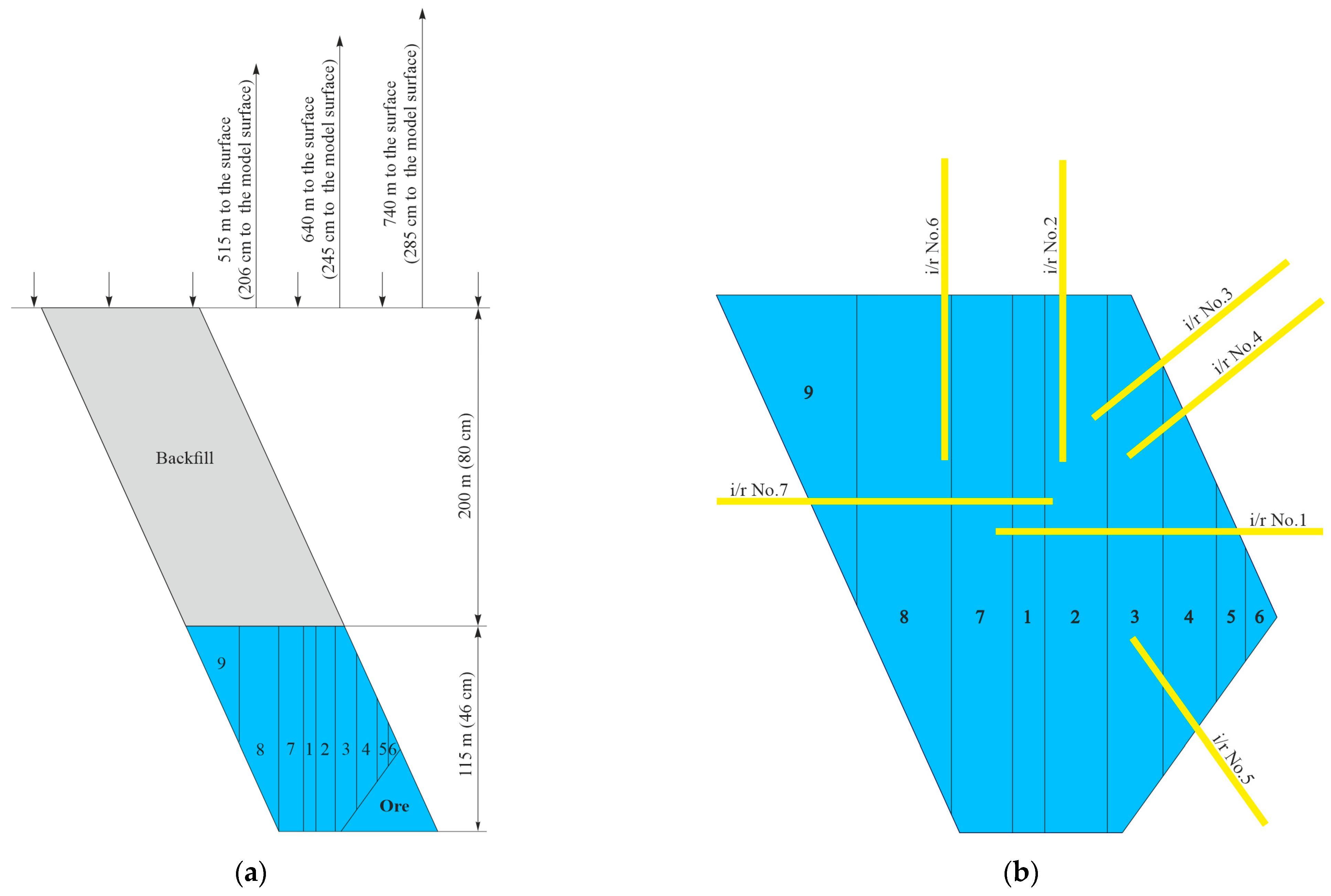
The model is formed from the hanging wall to the foot wall. For modeling the foot wall rocks, the equivalent material is a sand-cement mixture. The prepared mixture is tempered with water and, after thorough mixing, is put into the model. After a seven-day ageing, a laminated rock bench is formed, which is adjacent to the ore body. After seven days, an ore body is formed. For this purpose, an equivalent material from a mixture of sand, paraffin and solid oil, after thorough mixing and warming up in a water bath to 96–100 °C, is laid into the testing bench in a hot state and compacted. The material is laid in layers 4–5 cm thick. After cooling, a hanging wall is formed. First of all, a laminated rock bench adjacent to the ore body (talcose shales) is formed, and after seven days, the equivalent material of the hanging wall (shales) is laid. Material equivalent to ore is laid at a height of 46 cm (115 m in situ). The equivalent backfill material (a mixture of sand and solid oil) is laid into the model in layers from 2 to 6 cm thick, followed by compaction. The model, when formed completely, is allowed to settle for 28 days until the final hardening of the cement–sand mixture. The backfill material is formed above the tested stopes 80 cm high (200 m in situ).
After applying the load, the model is aged until the displacements are stabilised. A scheme of the equivalent materials model and the order of mining the stopes from the hanging wall to the foot wall is shown in Figure 4a. To control the deformations of the stope geometric parameters, indicator rulers (i/r) are used (Figure 4b).
The mass deformations around the extraction stopes of 740–840 m, 840–940 m, 940–1040 m levels are studied to reveal the influence of the mining depth. The testing bench is 126 cm high. Thus, when modeling the entire rock mass on the accepted scale, the height of the testing bench should be: for the stope at 740–840 m level is 332 cm; for 840–940 m is 371 cm; for 940–1040 m is 411 cm. The part of rock mass missed on the model should be compensated for by surcharging. On the model, the overlying rock stratum is compensated for in the modeling as follows:
- 740–840 m level (strata height is 515 m in situ or 206 cm on the model) applied load is 82 kg;
- 840–940 m level (strata height is 640 m in situ or 206 cm on the model) applied load is 102 kg;
- 940–1040 m level (strata height is 515 m in situ or 206 cm on the model) applied load is 118 kg.
4. Results and Discussion
4.1. Identifying Unstable Zones of Hanging Wall Rocks along the Ore Deposit Strike
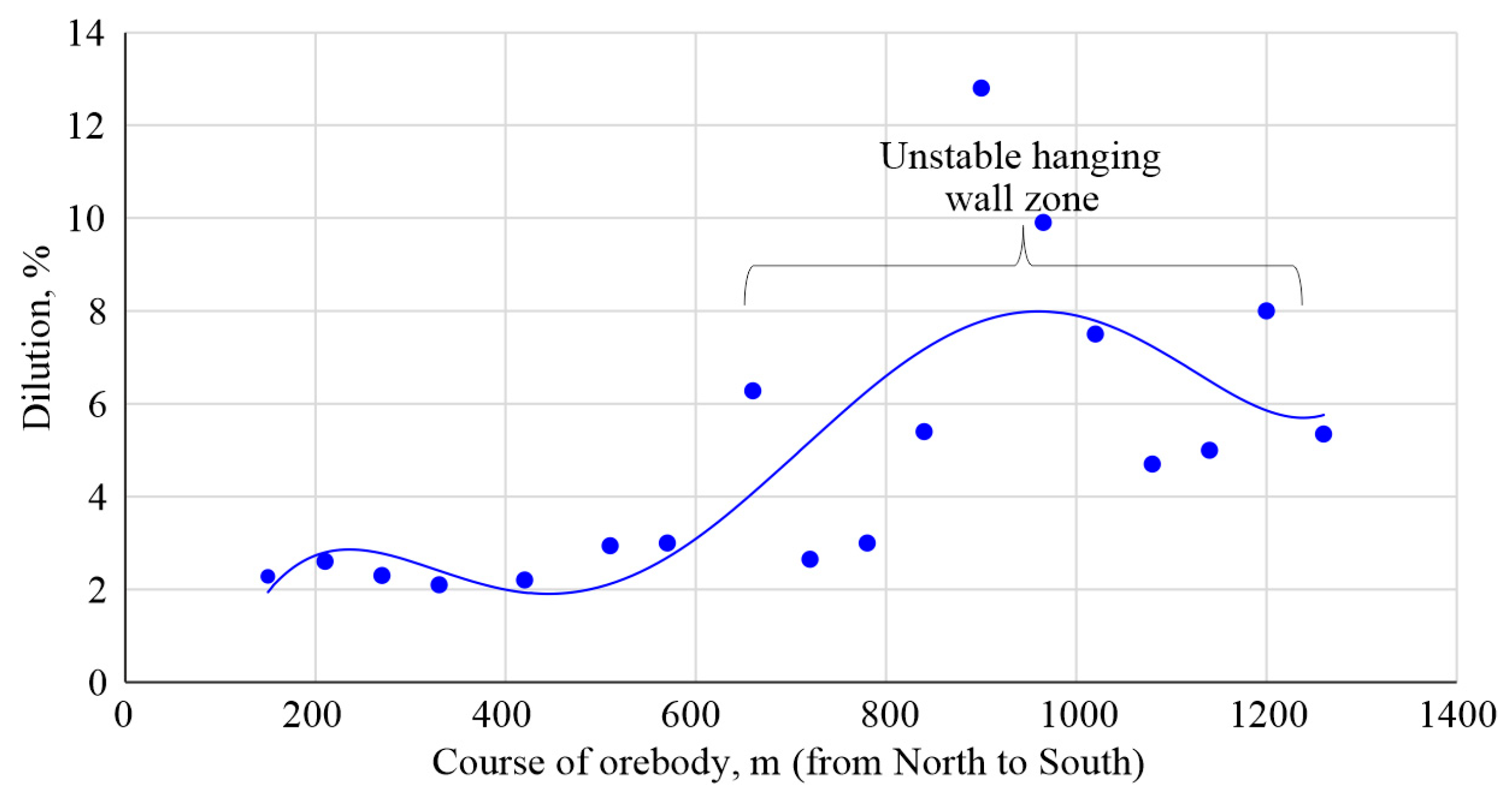
By processing the ore dilution data in the stopes and the location of the stopes in the deposit, it became possible to identify an area of the deposit with increased failure of the hanging wall rocks. Figure 5 shows the polynomial nature of the change in the dilution value of the ore mined from the stopes at the contact with the hanging wall rocks.
Analysis of Figure 5 shows that when mining the stopes in the direction from north to south of the deposit area within the interval of 0–600 m, the value of ore dilution is in the range of 2%–3%. Here, the achieved value of dilution is mainly caused by the presence of ferruginous quartzite interlayers in the ore, and the spalling of hanging wall rocks is minimal here. The value of ore dilution in the stopes of the deposit area within the interval of 600–1200 m rapidly increases and reaches 4%–8% with a maximum value of 12%. Here, the achieved value of dilution is caused by the hanging wall rocks failure into the stopes, which is clearly seen in Figure 5.
After 1200 m in the southern part of the deposit, the intensity of dilution gradually decreases. The results obtained indicate that the largest volumes of the hanging wall rocks failure into the stopes are observed in the ore deposit area within the interval of 600–1200 m, which represents the entire central part of the deposit and the beginning of the southern part. As a result of comparing the data on the ore deposit geological structure at 740–840 m level (detailed in Section 2) and the unstable area along the ore deposit strike within the interval of 600–1200 m, the most important averaged source data have been determined, which are subsequently used to perform physical modeling of the hanging wall rocks deformations, namely:
- average deposit thickness;
- angle of the deposit slope;
- type of rocks in the hanging wall and foot wall;
- physical and mechanical properties of ore and rocks in the hanging wall and foot wall;
- geometrical parameters of extraction stopes.
The forms of rock pressure manifestation and the value of dilution when mining the stopes of the foot wall have also been analysed. The ore dilution here is in the range of 0%–2%. It has been determined that the foot wall stopes of the deposit are located in the zone of a reduced stress state due to the protective effect of backfilling in the mined-out and backfilled stopes located above. As a result, their structural elements, being in the zone of reduced stresses, remain stable. Therefore, in the stopes near the ore deposit foot wall, disturbances of the stope space contours are almost not observed, or there is a slight fall of the backfill from the bottom above the mined-out and backfilled stopes.
4.2. Hanging Wall Rocks Deformation When Mining the Extraction Stopes
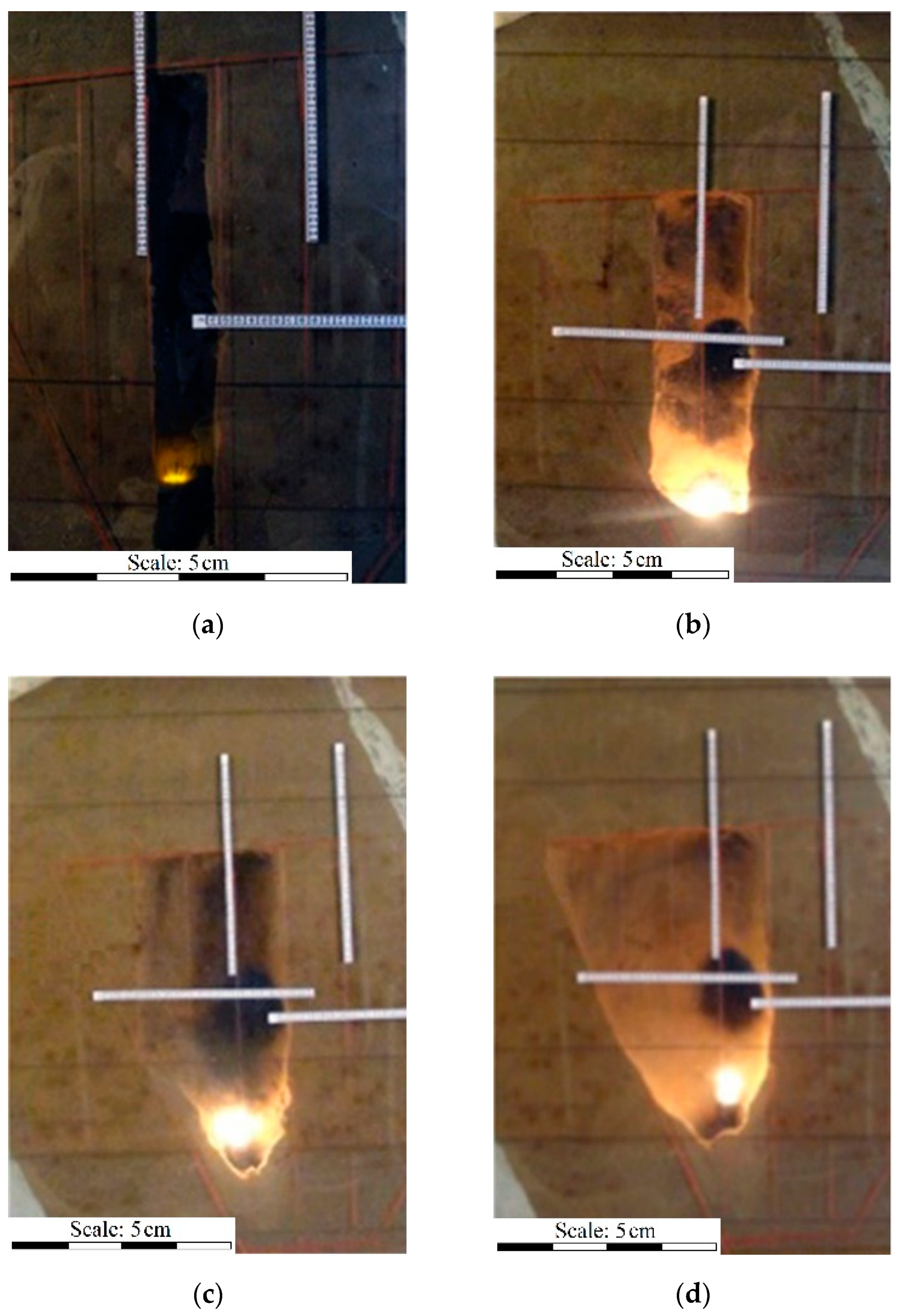
Initially the formation of the slot in the hanging wall stope (Figure 6a, stage 1) are modelled. To control the hanging wall state before creating the slot, indicator rulers Nos. 3, 4, 5 are added. Before modeling the next stage, readings are taken on indicator rulers Nos. 1, 2, 3, 4, 5, 6, 7. There are no deformations and displacements in the mass adjacent to the mined-out space.
The next stage is to reproduce the mining of the next layer in the direction of the hanging wall (Figure 6b, stage 2), which leads to the outcrop of the floor pillar by 15 cm, which corresponds to 37.5 m in situ. Deformations and displacements in the mass adjacent to the mined-out space are not recorded by indicator rulers No. 1, 2, 3, 4, 5, 6, 7.
The final stage in mining the hanging wall stope is the backfilling of the mined-out space. After the rock failure, deformations and displacements in the mass adjacent to the mined-out space before backfilling the stope are not noted. The equivalent backfill material (a mixture of sand and solid oil) is laid in the model in layers and compacted. As a result of the hanging wall rocks failure, 9% more equivalent material for backfilling is required than planned. Furthermore, the creation of a slot in the foot wall stope (Figure 7a, stage 5) and the breaking of the first layer towards the foot wall (Figure 7b, stage 6) are modelled.
There are no deformations and displacements in the mass adjacent to the mined-out space on the indicator rulers No. 1, 2, 6, 7. Then, mining of the next vertical layer towards the foot wall (Figure 7c, stage 7) is modelled. Before starting to model at stage 4, readings are taken on indicator rulers No. 1, 2, 6, 7. There are no deformations and displacements in the mass adjacent to the mined-out space.
Furthermore, mining of the stope is modelled up to the foot wall (Figure 7d, stage 8). In this case, floor pillar outcrop is 28 cm, which corresponds to 70 m in situ. The final stage in mining the foot wall stope is to model the backfilling of the mined-out space. Before backfilling the mined-out space, readings are taken on indicator rulers No. 1, 2, 6, 7. There are also no deformations and displacements in the mass adjacent to the mined-out space.
Also, the mining of stopes at 840–940 and 940–1040 m levels an analogical research for handing and foot wall by increasing the load on the model have been studied. An increase in the value of deformations is noted with an increase in the value of the load applied to the model according to indicator rulers Nos. 3 and No. 4—from the side of the hanging wall, No. 5—in the sloping stope bottom (Table 2). With an increase in the value of the applied load after the failure in the layer of unstable talcose shales, an increase in the collapse cavity is noted, but somewhat further already in the mass of quartz-chlorite-sericite shales. There are also no deformations and displacements in the mass adjacent to the mined-out space of the handing wall stope.
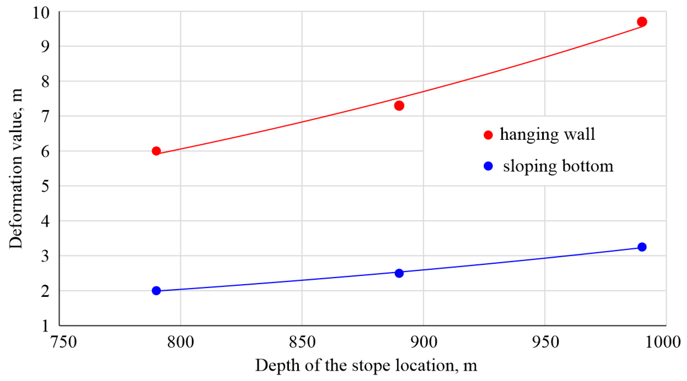
Based on the results of physical modeling the deformation (failure) values of the hanging wall rocks into the stopes and in the ore mass near the sloping bottom with the model fracturing development, it is possible to determine the dependences of their change with an increase in the depth of mining (Figure 8).
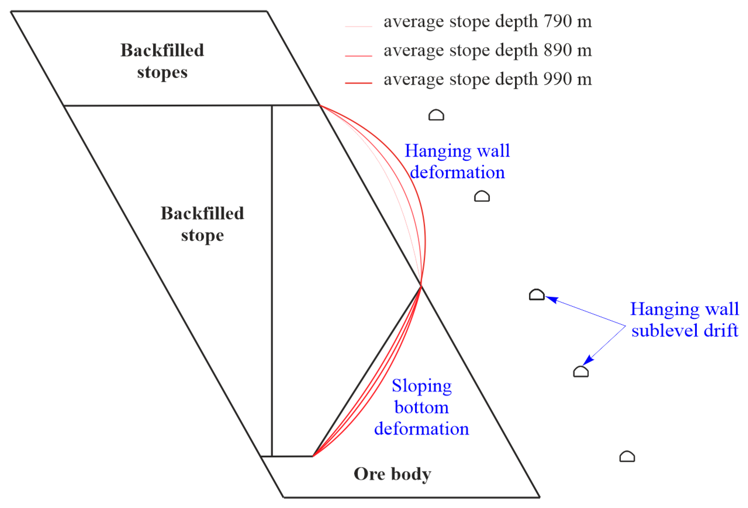
Analysis of Figure 8 shows that the deformation value of the hanging wall rocks with subsequent failure into the stope and deformations of the ore mass in the sloping bottom change exponentially with an increase in the depth of the stope location. It should be noted that the dynamics of the increase in rock deformations in the hanging wall is noticeably higher, since their increment in the depth interval of 790–990 m is 4 m, and in the sloping bottom is 1.1 m. If the ore mass cleavage in the sloping bottom does not have a negative effect on the quality of the ore mined from the stope, then the failure of rocks in the hanging wall, on the contrary, leads to dilution of the mined ore and deterioration of its quality. Broken ore in the stope with an iron content of 60%–63% is diluted with rocks of a hanging wall with an iron content of 20%–30%. This leads to its dilution. The areas of deformations development around the stope with an increase in the depth of mining are illustrated in Figure 9.
In addition to the rocks failure influence on the quality of mineral, another significant threat is increasing—the propagation of the rocks failure to the drifts of the hanging wall and the possibility of their destruction. The drifts in the hanging wall are located 20–25 m from the ore deposit, but at 940–1040 m level, when mining the stopes, the deformation value of the rocks in the hanging wall will reach 10 m or more, and mass fracturing will develop probably to an even greater distance. Since people, transport equipment and a ventilation stream move in the drifts of the hanging wall, therefore, damage to these drifts can cause both a serious danger to people and paralyze the proper functioning of the mine workings on the horizons.
Insignificant ore mass deformations and the fractures occurring in the sloping bottom of a stope will have a positive effect on ore reserves breaking in the stopes that will be located under it. The ore mass will be preliminarily weakened by the impact of the stope mining, and less explosive is likely to be required to mine the reserves. This direction is relevant, is of scientific interest, and requires special research.
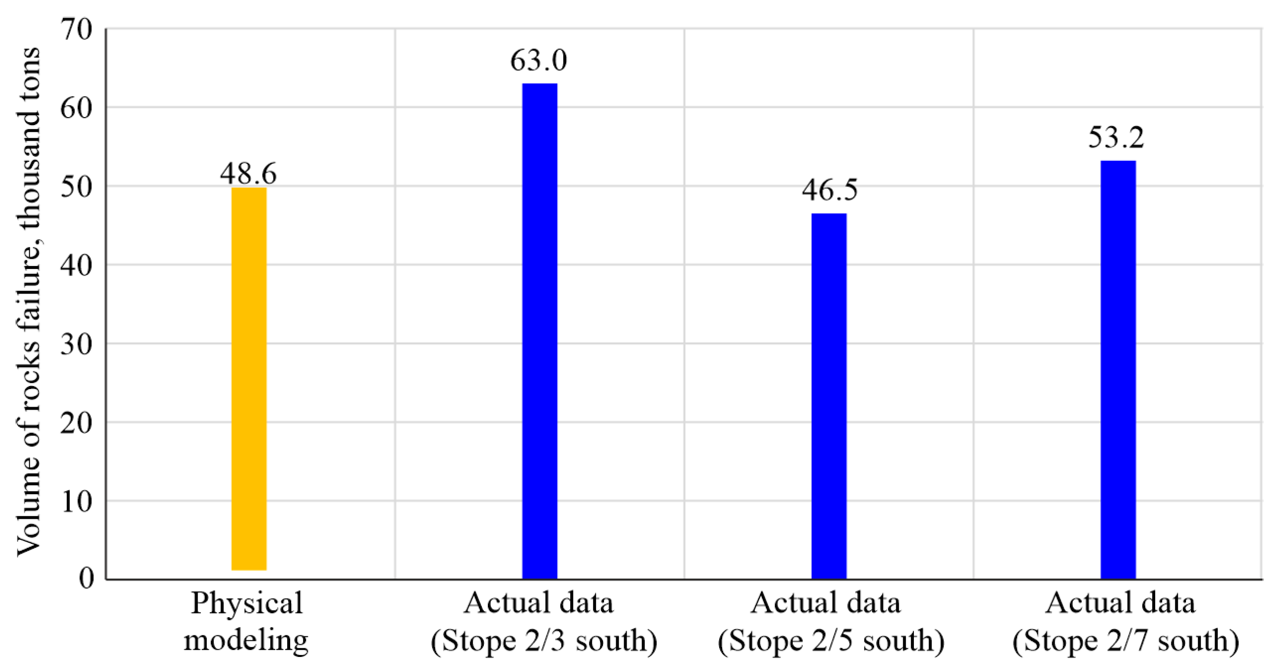
The results of the performed physical modeling are characterised by acceptable reliability, which is confirmed by the actual data on the ore dilution with collapsed rocks during the mining of stopes 2/3 south, 2/5 south, 2/7 south at 740–840 m level (Figure 10). Thus, according to the results of physical modeling, the volume of rocks failure is 48,500 tons at a value of a steeply dipping outcrop of 43 m, a stope width of 30 m and a rock density of 2.7 tons/m3.
The volume of actual rocks failure during the mining of stopes 2/3 south, 2/5 south, 2/7 south is in the range of 46,000–63,000 tons. This testifies to the high reliability and convergence of the results obtained. Based on the modeling results and actual data from the mine, the facts of the hanging wall rocks failure into the stopes have been recorded in the case of their low stability and the formation of a steeply dipping outcrop of stopes of at least 40 m and their width of 30 m. Thus, even at the 740–840 m level, when the area of steeply dipping outcrop of stopes with a value of 1200 m2 is formed, unstable rocks in the hanging wall are prone to large-volume failure.
The geological structure analysis of the hanging wall rocks along the depth of the ore body indicates an increase in the area of low-resistant quartz-chlorite-sericite shales propagation with low hardness of f = 4–9 in the hanging wall rocks in the central and southern parts of the deposit, which occurs at a depth of 400 m is 60 m; 640 m is 150 m, 740 m is 330 m, 840 m is 600 m. From this it follows that with an increase in the depth of mining within the depth intervals of 840–1140 m, the hazardous phenomena of the hanging wall rocks failure will only intensify, and the intensity of their manifestation in the stopes along the length of the ore deposit will increase.
Thus, for the successful mining of stopes within the depth interval of 840–1140 m, it is necessary to optimise the parameters of the stope and achieve its stable values: height, width and size of the steeply dipping outcrop. Also, taking into account the low natural stability of the hanging wall rocks in the central and southern parts of the deposit, it is recommended to consider the possibility of preserving the ore pillar in the hanging wall until the ore is broken and drawn from the rest of the stope in order to increase the contact area of the ore mass with weak rocks of the hanging wall.
5. Conclusions
As a result of the research, the following scientific and practical results have been obtained, which are useful for an effective technology for ore mining in unstable rocks:
- During mining within the depth interval of 640–940 m in the central and southern zones of the deposit, problems arise with the hanging wall rocks’ stability, represented by quartz-chlorite-sericite shales, sometimes talcose shales of low hardness of f = 4–9 that do not withstand significant outcrops in time. A decrease in stability is manifested in the form of a failure of the hanging wall rocks into the stope at the contact with its steeply dipping outcrop. The ore dilution with waste rocks at the contact with the hanging wall rocks in some stopes increases from the standard 5.0% to 12.0%.
- It has been determined that the value of ore dilution in the stopes of the deposit area along the strike within the interval of 600–1200 m rapidly increases and reaches 4–8% with a maximum value of 12%. The achieved dilution value is caused by the hanging wall rocks failure in the stopes. The results obtained indicate that the largest volumes of the hanging wall rocks failure in the stopes are observed in the ore deposit area within the interval of 600–1200 m, which represents the entire central part of the deposit and the beginning of the southern part. As a result of comparing the data on the ore deposit geological structure at 740–840 m level and the unstable area along the ore deposit strike within the interval of 600–1200 m, the most important averaged source data have been determined, which are used to perform physical modeling.
- It has been determined by means of physical modeling on equivalent materials that the deformation value of hanging wall rocks with subsequent failure in the stope and ore mass deformation in the sloping bottom change exponentially with an increase in the depth of the stope location. The dynamics of increasing rock deformations in the hanging wall is noticeably higher, since their increment in the depth interval 790–990 m is 4 m, and in the sloping bottom is 1.1 m. Broken ore in the stope with an iron content of 60%–63% is diluted with hanging wall rocks with an iron content of 20%–30%.
- The results of the performed physical modeling are characterised by acceptable reliability, which is confirmed by the actual data on the ore dilution with collapsed rocks during the mining of stopes. Based on the results of physical modeling, the volume of rocks failure is 48,500 tons. The volume of actual rocks failure during the mining of stopes 2/3 south, 2/5 south, 2/7 south is in the range of 46,000–63,000 tons. This testifies to the high reliability and convergence of the results obtained.
- The probability increases of the rocks failure area propagation to the hanging wall drifts with their subsequent destruction. The drifts in the hanging wall are located 20–25 m from the ore deposit, but at 940–1040 m level, when mining the stopes, the deformation value of the hanging wall rocks will reach 10 m or more, and mass fracturing will develop to an even greater distance from destruction. Therefore, damage to these drifts can cause both a serious danger to people and paralyze the proper functioning of the mine workings on the horizons.
- Based on the modeling results and actual data from the mine, it has been revealed that the facts of the hanging wall rocks failure into the stopes have been recorded in the case of their low stability and the formation of a steeply dipping outcrop of stopes of at least 40 m and their width of 30 m. Thus, even at 740–840 m level, when the area of steeply dipping outcrop of stopes with a value of 1200 m2 is formed, unstable rocks in the hanging wall are prone to large-volume failure.
- For successful mining of stopes and the stability of their elements within the depth interval of 840–1140 m, it is recommended to optimise the parameters: height, width and size of the steeply dipping outcrop. Also, taking into account the low natural stability of the hanging wall rocks in the central and southern parts of the deposit and with the purpose of increasing the contact area of the ore mass with the weak rocks of the hanging wall, it is recommended to consider the possibility of preserving the ore pillar in the hanging wall until the ore is broken and drawn from the rest part of the stope.
Author Contributions
Conceptualisation, O.B. and M.P.; methodology, M.P.; software, V.L.; validation, M.P., S.Z. and K.S.; formal analysis, M.P.; investigation, S.Z.; resources, M.P.; data curation, K.S.; writing—original draft preparation V.L., K.S.; writing—review and editing, V.L.; visualisation, V.L.; supervision, S.Z.; project administration, O.B.; funding acquisition, O.B. All authors have read and agreed to the published version of the manuscript.
Funding
This study was carried out as part of the project “Belt and Road Initiative Institute for Chinese-European studies (BRIICES)” and was funded by the Guangdong University of Petrochemical Technology.
Data Availability Statement
Data are contained within the article.
Acknowledgments
The team of authors express their gratitude to the editors and reviewers for valuable recommendations that have been taken into account to improve significantly the quality of this paper. The authors are also grateful to Andrii Mykolaiovych Zubko and Volodymyr Yuriiovych Usatyi, specialists of the Zaporizhzhia Iron Ore Plant for valuable advice and assistance in setting the research problems. Special gratitude to the Scientific-research mining institute (Kryvyi Rih) for the opportunity to conduct physical modeling.
Conflicts of Interest
The authors declare no conflict of interest.
References
- Wei, Y.; Xu, D.; Zhang, K.; Cheng, J. Research on the innovation incentive effect and heterogeneity of the market-incentive environmental regulation on mineral resource enterprises. Environ. Sci. Pollut. Res. 2021, 1–14. [Google Scholar] [CrossRef]
- Medunić, G.; Mondol, D.; Rađenović, A.; Nazir, S. Review of the latest research on coal, environment, and clean technologies. Rud. Geol. Naft. Zb. 2018, 33, 13–21. [Google Scholar] [CrossRef]
- Sekerin, V.; Dudin, M.; Gorokhova, A.; Bank, S.; Bank, O. Mineral resources and national economic security: Current features. Min. Miner. Depos. 2019, 13, 72–79. [Google Scholar] [CrossRef]
- Churin, V.; Vysotskaya, N.; Sizova, Y.; Danilina, E.; Gorelov, D. Distribution of mineral extraction revenue: Overview of international practice. Min. Miner. Depos. 2019, 13, 66–74. [Google Scholar] [CrossRef] [Green Version]
- Pivniak, H.H.; Pilov, P.I.; Pashkevych, M.S.; Shashenko, D.O. Synchro-mining: Civilized solution of problems of mining regions’ sustainable operation. Nauk. Visnyk Natsionalnoho Hirnychoho Universytetu 2012, 131–138. [Google Scholar]
- Ursul, A.; Tirdea, T.; Ursul, T. Limits to growth and achievement of global sustainability. Phlos. Cosmol. 2018, 21, 42–51. [Google Scholar] [CrossRef] [PubMed]
- Melnyk, T. Ukraine and its future in a globalised international community. Ukr. Policymaker 2018, 3, 17–28. [Google Scholar] [CrossRef]
- Yablokov, A.; Levchenko, V.; Kerzhentsev, A. The Biosphere as a living system. On the harmonization of human and biosphere. Philos. Cosmol. 2018, 18, 52–83. [Google Scholar]
- Buzylo, V.; Pavlychenko, A.; Savelieva, T.; Borysovska, O. Ecological aspects of managing the stressed-deformed state of the mountain massif during the development of multiple coal layers. In E3S Web of Conferences, Proceedings of the XII International Scientific and Practical Conference, Berdiansk, Ukraine, 4–8 September 2018; EDP Sciences: Les Ulis, France, 2018; Volume 60, p. 00013. [Google Scholar] [CrossRef] [Green Version]
- Lyashenko, V.I. Ecological safety of uranium production in Ukraine. Gornyi Zhurnal 2014, 4, 113–116. [Google Scholar]
- Menshov, O.; Spassov, S.; Camps, P.; Vyzhva, S.; Pereira, P.; Pastushenko, T.; Demidov, V. Soil and dust magnetism in semi-urban area Truskavets, Ukraine. Environ. Earth Sci. 2020, 79, 1–10. [Google Scholar] [CrossRef]
- Nurpeissova, M.; Bekbassarov, S.; Bek, A.; Kyrgizbaeva, G.; Turisbekov, S.; Ormanbekova, A. The geodetic monitoring of the engineering structures stability conditions. J. Eng. Appl. Sci. 2020, 12, 9151–9163. [Google Scholar] [CrossRef]
- Fernandez-Lozano, J.; Andres-Bercianos, R. Natural or induced mass movements: New insights into slope instability recognition in the province of León. Geogaceta 2018, 64, 99–102. [Google Scholar]
- Petlovanyi, M.; Malashkevych, D.; Sai, K.; Zubko, S. Research into balance of rocks and underground cavities formation in the coal mine flowsheet when mining thin seams. Min. Miner. Depos. 2020, 14, 66–81. [Google Scholar] [CrossRef]
- Nurpeisova, M.B.; Sarybaiev, O.A.; Kurmanbaiev, O.S. Study of Regularity of Geomechanical Processes Development while Developing Deposits by the Combined Way. Nauk. Visnyk Natsionalnoho Hirnychoho Universytetu 2016, 4, 30–36. [Google Scholar]
- Ericsson, M.; Löf, A. Iron ore outlook: Facing a slow climb out of the Pit. Eng. Min. J. 2009, 210, 36–41. [Google Scholar]
- Ericsson, M. Global iron ore survey: The race continues between supply and demand. Eng. Min. J. 2007, 208, 60–66. [Google Scholar]
- Yellishetty, M.; Ranjith, P.G.; Tharumarajah, A. Iron ore and steel production trends and material flows in the world: Is this really sustainable? Resour. Conserv. Recycl. 2010, 54, 1084–1094. [Google Scholar] [CrossRef]
- Holmes, R.J.; Lu, L. Introduction: Overview of the global iron ore industry. In Iron Ore: Mineralogy, Processing and Environmental Sustainability; Woodhead Publishing: Sawston, UK, 2015; pp. 1–42. [Google Scholar] [CrossRef]
- Yellishetty, M.; Mudd, G.M. Substance flow analysis of steel and long term sustainability of iron ore resources in Australia, Brazil, China and India. J. Clean. Prod. 2014, 84, 400–410. [Google Scholar] [CrossRef]
- USGS—United States Geological Survey. Mineral Resources Program. 2018. Available online: https://pubs.usgs.gov/periodicals/mcs2021/mcs2021-iron-ore.pdf (accessed on 10 July 2021).
- Kalinichenko, V.; Pysmennyi, S.; Shvaher, N.; Kalinichenko, O. Selective underground mining of complex structured ore bodies of Kryvyi Rih Iron Ore Basin. In E3S Web of Conferences, Proceedings of the XII International Scientific and Practical Conference, Berdiansk, Ukraine, 4–8 September 2018; EDP Sciences: Les Ulis, France, 2018; Volume 60, p. 00041. [Google Scholar] [CrossRef] [Green Version]
- Kurylo, M.; Plotnikov, O. Quality parameters of Ukrainian iron ore deposits and their compliance with modern technological processes. In Proceedings of the 20th SGEM International Multidisciplinary Scientific GeoConference: Science and Technologies in Geology, Exploration and Mining, Albena, Bulgaria, 18–24 August 2020. [Google Scholar] [CrossRef]
- Sinchuk, O.; Kupin, A.; Sinchuk, I.; Rohoza, M.; Plieshkov, P. Certain aspects concerning the development of a functioning scheme of the auto-mated system to control energy flows of underground iron-ore enterprises. Min. Miner. Depos. 2020, 14, 101–111. [Google Scholar] [CrossRef]
- Kurilo, M.; Plotnikov, O. Geological and economic evaluation of iron ore deposits of pravoberezhny area (Ukraine). In Proceedings of the International Multidisciplinary Scientific GeoConference: Surveying Geology and Mining Ecology Management (SGEM), Albena, Bulgaria, 17–26 June 2014; Volume 1, pp. 145–152. [Google Scholar]
- Bazaluk, O.; Petlovanyi, M.; Lozynskyi, V.; Zubko, S.; Sai, K.; Saik, P. Sustainable iron ore mining in Ukraine with Backfilling worked-out area. Sustainability 2021, 13, 834. [Google Scholar] [CrossRef]
- Petlovanyi, M.; Kuzmenko, O.; Lozynskyi, V.; Popovych, V.; Saik, P.; Sai, K. Review of man-made mineral formations accumulation and prospects of their developing in mining industrial regions in Ukraine. Min. Miner. Depos. 2019, 13, 24–38. [Google Scholar] [CrossRef]
- Panchenko, V. Openwork scheduling for steep-grade iron-ore deposits with the help of near-vertical layers. Rozrobka Rodovyshch 2021, 15, 87–95. [Google Scholar]
- Kurilo, M.; Plotnikov, O. Commercial significance of high-grade iron ore deposits on example of Belozersky area (Ukraine). In Proceedings of the International Multidisciplinary Scientific GeoConference: Surveying Geology and Mining Ecology Management (SGEM), Albena, Bulgaria, 18–24 June 2015; pp. 85–90. [Google Scholar] [CrossRef]
- Forster, K.; Milne, D.; Pop, A. Mining and rock mass factors influencing hangingwall dilution. In Rock Mechanics: Meeting Society’s Challenges and Demands, Proceedings of the 1st Canada-US Rock Mechanics Symposium, Vancouver, BC, Canada, 27–31 May 2007; CRC Press: Boca Raton, FL, USA, 2007; pp. 1361–1366. [Google Scholar] [CrossRef]
- Zhu, X.; Zheng, W.; Zhang, H.; Guo, Y. Time-varying international market power for the Chinese iron ore markets. Resour. Policy 2019, 64, 101502. [Google Scholar] [CrossRef]
- Dychkovskyi, R.; Vladyko, O.; Maltsev, D.; Cabana, E.C. Some aspects of the compatibility of mineral mining technologies. Rud. Geol. Naft. Zb. 2018, 33, 73–82. [Google Scholar] [CrossRef] [Green Version]
- Kalybekov, T.; Rysbekov, K.; Nauryzbayeva, D.; Toktarov, A.; Zhakypbek, Y. Substantiation of averaging the content of mined ores with account of their readiness for mining. In E3S Web of Conferences, Proceedings of the 14th International Research and Practical Conference, Berdiansk, Ukraine, 7–11 September 2020; EDP Sciences: Les Ulis, France, 2020; Volume 201, p. 01039. [Google Scholar] [CrossRef]
- Rysbekov, K.; Toktarov, A.; Kalybekov, T.; Moldabayev, S.; Yessezhulov, T.; Bakhmagambetova, G. Mine planning subject to prepared ore reserves rationing. In E3S Web of Conferences, Proceedings of the 2nd International Conference Essays of Mining Science and Practice, Dnipro, Ukraine, 22–24 April 2020; EDP Sciences: Les Ulis, France, 2020; Volume 168, p. 00016. [Google Scholar] [CrossRef]
- Petlovanyi, M.; Lozynskyi, V.; Zubko, S.; Saik, P.; Sai, K. The influence of geology and ore deposit occurrence conditions on dilution indicators of extracted reserves. Rud. Geol. Naft. Zb. 2019, 34, 83–91. [Google Scholar] [CrossRef] [Green Version]
- Azarian, V.; Lutsenko, S.; Zhukov, S.; Skachkov, A.; Zaiarskyi, R.; Titov, D. Applied scientific and systemic problems of the related ore-dressing plants interaction in the event of decommissioning the massif that separates their quarries. Min. Miner. Depos. 2020, 14, 1–10. [Google Scholar] [CrossRef] [Green Version]
- Baibatsha, A.; Dyussembayeva, K.; Bekbotayeva, A. Study of tails enrichment factory Zhezkazgan as a technogenic ore deposits. In Proceedings of the International Multidisciplinary Scientific GeoConference Surveying Geology and Mining Ecology Management (SGEM), Albena, Bulgaria, 30 June–6 July 2016; Volume 1, pp. 579–586. [Google Scholar] [CrossRef]
- Stupnik, M.; Shatokha, V. History and current state of mining in the Kryvyi Rih iron ore deposit. In Iron Ores; IntechOpen: London, UK, 2021. [Google Scholar] [CrossRef]
- Pysmenniy, S.; Shvager, N.; Shepel, O.; Kovbyk, K.; Dolgikh, O. Development of resource-saving technology when mining ore bodies by blocks under rock pressure. In E3S Web of Conferences, Proceedings of the The International Conference on Sustainable Futures: Environmental, Technological, Social and Economic Matters (ICSF), Kryvyi Rih, Ukraine, 20–22 May 2020; EDP Sciences: Les Ulis, France, 2020; Volume 166, p. 02006. [Google Scholar] [CrossRef] [Green Version]
- Azaryan, A.A.; Batareyev, O.S.; Karamanits, F.I.; Kolosov, V.O.; Morkun, V.S. Ways to reduce ore losses and dilution in iron ore underground mining in Kryvbass. Sci. Innov. 2018, 14, 17–24. [Google Scholar] [CrossRef]
- Petlovanyi, M.; Ruskykh, V.; Zubko, S.; Medianyk, V. Dependence of the mined ores quality on the geological structure and properties of the hanging wall rocks. In E3S Web of Conferences, Proceedings of the 14th International Research and Practical Conference, Berdiansk, Ukraine, 7–11 September 2020; EDP Sciences: Les Ulis, France, 2020; Volume 201, p. 01027. [Google Scholar] [CrossRef]
- Stupnik, N.; Kalinichenko, V.; Kolosov, V.; Pismennyy, S.; Shepel, A. Modeling of stopes in soft ores during ore mining. Metall. Min. Ind. 2014, 6, 32–37. [Google Scholar]
- Khomenko, O.; Kononenko, M.; Petlovanyi, M. Investigation of stress-strain state of rock massif around the secondary chambers. In Progressive Technologies of Coal, Coalbed Methane, and Ores Mining; CRC Press: Boca Raton, FL, USA, 2014; pp. 253–258. [Google Scholar] [CrossRef]
- Lyashenko, V. Safety improving of mine preparation works at the ore mines. Bezopasnost’ Tr. Promyshlennosti 2018, 53–59. [Google Scholar] [CrossRef] [Green Version]
- Petlovanyi, M.V.; Ruskykh, V.V.; Zubko, S.A. Peculiarities of the underground mining of high-grade iron ores in anomalous geological conditions. J. Geol. Geogr. Geoecol. 2019, 28, 706–716. [Google Scholar] [CrossRef]
- Hefni, M.A.; Abdellah, W.R.E.; Ahmed, H.M. Factors influencing stope hanging wall stability and ore dilution in narrow-vein deposits: Part II. Geotech. Geol. Eng. 2020, 38, 3795–3813. [Google Scholar] [CrossRef]
- Nurpeisova, M.B.; Kurmanbaev, O.S. Laws of devolopment of geomechanical processes in the rock mass maykain mine. News Natl. Acad. Sci. Repub. Kazakhstan 2016, 6, 109–115. [Google Scholar]
- Henning, J.G.; Mitri, H.S. Numerical modelling of ore dilution in blasthole stoping. Int. J. Rock Mech. Min. Sci. 2007, 44, 692–703. [Google Scholar] [CrossRef]
- Kasanda, T.B.; Bowa, V.M. Causes and impact of hangingwall instability in open stopes: A case of Chifupu project in Zambia. Geotech. Geol. Eng. 2019, 38, 475–495. [Google Scholar] [CrossRef]
- Urli, V.; Esmaieli, K. A stability-economic model for an open stope to prevent dilution using the ore-skin design. Int. J. Rock Mech. Min. Sci. 2016, 82, 71–82. [Google Scholar] [CrossRef]
- Qi, C.; Chen, Q. Evolutionary random forest algorithms for predicting the maximum failure depth of open stope hangingwalls. IEEE Access 2018, 6, 72808–72813. [Google Scholar] [CrossRef]
- Vallejos, J.A.; Díaz, L. A new criterion for numerical modelling of hangingwall overbreak in open stopes. Rock Mech. Rock Eng. 2020, 53, 4559–4581. [Google Scholar] [CrossRef]
- Abdellah, W.R.E.; Hefni, M.A.; Ahmed, H.M. Factors influencing stope hanging wall stability and ore dilution in narrow-vein deposits: Part 1. Geotech. Geol. Eng. 2019, 38, 1451–1470. [Google Scholar] [CrossRef]
- Umar, S.B. Modelling of caving and deformation mechanisms of the hangingwall of the Printzsköld oreboby at Malmberget mine. J. S. Afr. Inst. Min. Metall. 2017, 117, 351–360. [Google Scholar] [CrossRef] [Green Version]
- Barba, T.F.V.; Nordlund, E. Numerical analyses of the hangingwall failure due to sublevel caving: Study case. Int. J. Min. Miner. Eng. 2013, 4, 201–223. [Google Scholar] [CrossRef]
- Umar, S.B.; Edelbro, C. Influence of large-scale structures on the stability of the hangingwall in a caving mine: A modelling study. Int. J. Min. Miner. Eng. 2016, 7, 294–312. [Google Scholar] [CrossRef]
- Basarir, H.; Sun, Y.; Li, G. Gateway stability analysis by global-local modeling approach. Int. J. Rock Mech. Min. Sci. 2019, 113, 31–40. [Google Scholar] [CrossRef]
- Sun, Y.; Li, G.; Zhang, J.; Qian, D. Experimental and numerical investigation on a novel support system for controlling roadway deformation in underground coal mines. Energy Sci. Eng. 2019, 8, 490–500. [Google Scholar] [CrossRef] [Green Version]
- Heidarzadeh, S.; Saeidi, A.; Rouleau, A. The damage-failure criteria for numerical stability analysis of underground excavations: A review. Tunn. Undergr. Space Technol. 2021, 107, 103633. [Google Scholar] [CrossRef]
- Yang, Y.; Xu, D.; Liu, F.; Zheng, H. Modeling the entire progressive failure process of rock slopes using a strength-based criterion. Comput. Geotech. 2020, 126, 103726. [Google Scholar] [CrossRef]
- Shashenko, A.; Gapieiev, S.; Solodyankin, A. Numerical simulation of the elastic-plastic state of rock mass around horizontal workings. Arch. Min. Sci. 2009, 54, 341–348. [Google Scholar]
- Bondarenko, V.; Symanovych, G.; Koval, O. The mechanism of over-coal thin-layered massif deformation of weak rocks in a longwall. In Geomechanical Processes during Underground Mining; CRC Press: Boca Raton, FL, USA, 2012; pp. 41–44. [Google Scholar] [CrossRef]
- Petlovanyi, M. Influence of configuration chambers on the formation of stress in multi-modulus mass. Min. Miner. Depos. 2016, 10, 48–54. [Google Scholar] [CrossRef] [Green Version]
- Baklashov, I.A. Geomechanics. In The Basis of Geomechanics; MGTU: Moscow, Russia, 2004; pp. 1–208. [Google Scholar]
- SNiP II-94-80. Underground Mining Workings; Stroiizdat: Moscow, Russia, 1982; pp. 1–31. [Google Scholar]
- Khomenko, O.; Kononenko, M.; Petlovanyi, M. Analytical modeling of the backfill massif deformations around the chamber with mining depth increase. In New Developments in Mining Engineering; Routledge: Abingdon, UK, 2015; pp. 265–269. [Google Scholar]
- Kuz’menko, A.; Furman, A.; Usatyy, V. Improvement of mining methods with consolidating stowing of iron-ore deposits on big depths. In New Techniques and Technologies in Mining: School of Underground Mining; Taylor & Francis Group: London, UK, 2010; pp. 131–136. [Google Scholar] [CrossRef]
- Petlovanyi, M.; Mamaikin, O. Assessment of an expediency of binder material mechanical activation in cemented rockfill. ARPN J. Eng. Appl. Sci. 2019, 14, 3492–3503. [Google Scholar]
- Zhautikov, F.B.; Isagulov, A.Z.; Zhautikov, B.A.; Romanov, V.I.; Babenko, A.A. Development and Implementation of a Device for the Separation of Metal and Slag During Tundish Filling. Metallurgist 2019, 63, 672–674. [Google Scholar] [CrossRef]
- Petlovanyi, M.V.; Zubko, S.A.; Popovych, V.V.; Sai, K.S. Physicochemical mechanism of structure formation and strengthening in the backfill massif when filling underground cavities. Vopr. Khimii Khimicheskoi Tekhnologii 2020, 6, 142–150. [Google Scholar] [CrossRef]
- Kuzmenko, O.; Petlyovanyy, M.; Heylo, A. Application of fine-grained binding materials in technology of hardening backfill construction. In Progressive Technologies of Coal, Coalbed Methane, and Ores Mining; CRC Press: Boca Raton, FL, USA, 2014; pp. 465–469. [Google Scholar] [CrossRef]
- Kuz’menko, O.; Petlyovanyy, M.; Stupnik, M. The influence of fine particles of binding materials on the strength properties of hardening backfill. In Annual Scientific-Technical Colletion: Mining of Mineral Deposits; CRC Press: Boca Raton, FL, USA, 2013; pp. 45–48. [Google Scholar] [CrossRef]
- Arslanov, M.Z.; Mustafin, S.A.; Zeinullin, A.A.; Kulpeshov, B.S.; Mustafin, T.S. Model for determining classification of filling materials hardening. News Natl. Acad. Sci. Repub. Kazakhstan 2020, 5, 6–12. [Google Scholar] [CrossRef]
- Russkikh, V.V.; Lapko, V.V.; Zubko, S.A. Development and adoption of new technical decisions for development of Yuzhno-Belozerskoye ore deposit under difficult mining and geological conditions. Nauk. Visnyk Natsionalnoho Hirnychoho Universytetu 2012, 5, 34–38. [Google Scholar]
- Chistyakov, E.; Ruskih, V.; Zubko, S. Investigation of the geomechanical processes while mining thick ore deposits by room systems with backfill of worked-out area. In School of Underground Mining: Geomechanical Processes during Underground Mining; CRC Press: Boca Raton, FL, USA, 2012; pp. 127–132. [Google Scholar] [CrossRef]
- Stupnik, M.; Kalinichenko, O.; Kalinichenko, V.; Pysmennyi, S.; Morhun, O. Choice and substantiation of stable crown shapes in deep-level iron ore mining. Rozrobka Rodovyshch 2018, 12, 56–62. [Google Scholar] [CrossRef] [Green Version]
- Nasonov, I.D.; Resin, V.I. Modelirovanie Fizicheskikh Protsessov v Gornom Dele; Akademii Gornykh Nauk: Moscow, Russia, 1999; p. 343. [Google Scholar]
Figure 1.
Characteristic zoning of an ore deposits with similar mining-and-geological conditions (740 m horizon section).
Figure 1.
Characteristic zoning of an ore deposits with similar mining-and-geological conditions (740 m horizon section).

Figure 2.
Technological elements of mining the ore deposit: (a) division of the deposit into stopes across the strike and its elements; (b) order of mining the stopes along the ore deposit area.
Figure 2.
Technological elements of mining the ore deposit: (a) division of the deposit into stopes across the strike and its elements; (b) order of mining the stopes along the ore deposit area.

Figure 3.
Schematic layout of extraction stopes at the contact with the hanging wall rocks with the fixation of their destruction zones.
Figure 3.
Schematic layout of extraction stopes at the contact with the hanging wall rocks with the fixation of their destruction zones.

Figure 4.
Scheme of the model and the order of mining the stopes in stages (a) and the scheme for arranging the indicator rulers when mining the stopes (b).
Figure 4.
Scheme of the model and the order of mining the stopes in stages (a) and the scheme for arranging the indicator rulers when mining the stopes (b).

Figure 5.
Distribution of the dilution value of ore mined from the stopes along the ore deposit strike.
Figure 5.
Distribution of the dilution value of ore mined from the stopes along the ore deposit strike.

Figure 6.
Modeling the stages of stope mining at the contact with hanging wall rocks: (a) stage 1; (b) stage 2; (c) stage 3; (d) stage 4.
Figure 6.
Modeling the stages of stope mining at the contact with hanging wall rocks: (a) stage 1; (b) stage 2; (c) stage 3; (d) stage 4.

Figure 7.
Modeling the stages of foot wall stope mining: (a) stage 5; (b) stage 6; (c) stage 7; (d) stage 8.
Figure 7.
Modeling the stages of foot wall stope mining: (a) stage 5; (b) stage 6; (c) stage 7; (d) stage 8.

Figure 8.
Dependence of the change in the deformation value of the hanging wall mass and ore mass near the sloping bottom with an increase in the depth of mining.
Figure 8.
Dependence of the change in the deformation value of the hanging wall mass and ore mass near the sloping bottom with an increase in the depth of mining.

Figure 9.
Areas of deformations development in the rocks of the hanging wall and sloping bottom with an increase in the depth of mining.
Figure 9.
Areas of deformations development in the rocks of the hanging wall and sloping bottom with an increase in the depth of mining.

Figure 10.
Areas of deformations development in the rocks of the hanging wall and sloping bottom with an increase in the depth of mining.
Figure 10.
Areas of deformations development in the rocks of the hanging wall and sloping bottom with an increase in the depth of mining.


Table 1.
Physical and mechanical properties of rocks and equivalent materials.
| Name of Rocks | Physical and Mechanical Properties of Equivalent Materials | Equivalent Materials, Component Proportion, % by Weight | |||||||
|---|---|---|---|---|---|---|---|---|---|
| Volumetric Weight, tons/m3 | Internal Friction Angle, Degree | Adhesion, MPa | Compression Strength, MPa | Sand | Cement | Solid Oil | Paraffin | Talc | |
| Quartz-chlorite-sericite shales | 2.0 | 26 | 0.5 | 0.55 | 95 | 5 | - | - | - |
| Hematite-martite ore | 2.0 | 22 | 0.03 | 0.05 | 96 | - | 3 | 1 | - |
| Sericite-chlorite-talcose shales | 2.0 | 15 | 0.01 | 0.03 | - | - | - | - | 100 |
| Backfill | 2.0 | 21 | 0.03 | 0.03 | 97 | - | 3 | - | - |
Table 2.
Results of the research on model and prototype deformations in hanging wall.
| Deformations of the Hanging Wall Rocks | |||
| Average stope depth | 790 | 890 | 990 |
| –model, cm | 2.4 | 2.7 | 3.2 |
| –prototype, m | 6.0 | 7.3 | 9.7 |
| Deformations of Rocks Adjacent to the Steeply Dipping Outcrop | |||
| Average stope depth | 790 | 890 | 990 |
| –model, cm | 0.8 | 1.0 | 1.3 |
| –prototype, m | 2.0 | 2.5 | 3.25 |
Publisher’s Note: MDPI stays neutral with regard to jurisdictional claims in published maps and institutional affiliations. |
© 2021 by the authors. Licensee MDPI, Basel, Switzerland. This article is an open access article distributed under the terms and conditions of the Creative Commons Attribution (CC BY) license (https://creativecommons.org/licenses/by/4.0/).
Share and Cite
MDPI and ACS Style
Bazaluk, O.; Petlovanyi, M.; Zubko, S.; Lozynskyi, V.; Sai, K. Instability Assessment of Hanging Wall Rocks during Underground Mining of Iron Ores. Minerals 2021, 11, 858. https://0-doi-org.brum.beds.ac.uk/10.3390/min11080858
AMA Style
Bazaluk O, Petlovanyi M, Zubko S, Lozynskyi V, Sai K. Instability Assessment of Hanging Wall Rocks during Underground Mining of Iron Ores. Minerals. 2021; 11(8):858. https://0-doi-org.brum.beds.ac.uk/10.3390/min11080858
Chicago/Turabian StyleBazaluk, Oleg, Mykhailo Petlovanyi, Serhii Zubko, Vasyl Lozynskyi, and Kateryna Sai. 2021. "Instability Assessment of Hanging Wall Rocks during Underground Mining of Iron Ores" Minerals 11, no. 8: 858. https://0-doi-org.brum.beds.ac.uk/10.3390/min11080858
Note that from the first issue of 2016, this journal uses article numbers instead of page numbers. See further details here.