Article

Application of Dual Silane Coupling Agent-Assisted Surface-Modified Quartz Powder in Epoxy Matrix for Performance Enhancement

1
School of Resources and Environmental Engineering, Wuhan University of Technology, Wuhan 430070, China
2
CNBM Research Institute for Advanced Glass Materials Group Co., Ltd., Bengbu 233018, China
3
(Anhui) National Innovation Center for Advanced Glass Materials, Bengbu 233000, China
4
State Key Laboratory of Float Glass New Technology, Bengbu 233018, China
5
Hubei Key Laboratory of Mineral Resources Processing and Environment, Wuhan University of Technology, Wuhan 430070, China
*
Author to whom correspondence should be addressed.
Submission received: 24 May 2022 / Revised: 13 June 2022 / Accepted: 17 June 2022 / Published: 21 June 2022
(This article belongs to the Special Issue Advances in Non-metallic Ore Separation)

Abstract

:
Quartz powder (QP) is an inorganic filler that is expected to significantly enhance the dielectric and mechanical properties of epoxy (EP)-based composites applied in copper clad laminates and epoxy molding compounds for 5G applications. As is well-known, the performance of the QP–EP composites is directly correlated with the dispersion effect and the compatibility of QP with an EP matrix. Herein, we propose the surface modification method of QP by mixing SCAs of different alkyl chain lengths that contain amino and carbonyl groups. Different characterization methods (FTIR, TGA, XPS, SEM, contact angle measurement, viscosity, and mechanical properties) and molecular dynamics simulation were adopted to study its effect and mechanism. Through dual SCA modification, the viscosity of QP–EP composites was reduced by 11.70%, and the flexural and tensile strengths increased by 16.89% and 30.01%, respectively. In addition, it was revealed that the superiority of dual SCAs originated from the synergistic effect between APTES and SPIS, it was the electrostatic repulsion force between the amino groups of the two SCAs that caused a steric hindrance that activated the steric stabilization effect of SPIS, thus resulting in better dispersion and excellent compatibility. Meanwhile, the amino and carbonyl groups of the SCA interacted with the EP matrix via chemical bonds and hydrogen bonds, thus strengthening the interfacial adhesion between the QP and EP matrix and improving the mechanical performance of QP–EP composites. These results are evidence of the potential of the proposed approach, which is based on the synergistic compounding of SCA with different molecular structures, in powder industrial applications.

1. Introduction

With the continued trend toward electronic device miniaturization, functionalization, and increased integration, the thermal stability, insulation, and mechanical properties of polymer composites have been extensively explored in recent years [1,2,3]. Epoxy resin (EP) is a type of thermosetting resin, which is widely used as a substrate material in technical applications, owing to its extraordinary properties. However, EP composites also exhibit significant disadvantages, such as high cross-linking density, brittleness, and a poor impact resistance, resulting in its poor mechanical performance and limited application. By selecting the appropriate filler, new macroscopic properties, such as improved fracture toughness and mechanical stiffness, can be induced in polymer composites, as shown in various reported studies [4,5,6].
Quartz powder (QP) is one of the most widely used inorganic fillers, which is extensively used in electronic applications, such as in copper clad laminates and epoxy molding compounds, owing to its superior electric insulation, good chemical resistance, high mechanical properties, and good thermal stability [7,8,9]. However, QP of small particle size tends to aggregate because of the high surface energy, and it has bad compatibility with a nonpolar polymer matrix because of its polarized surface, which results in an uneven distribution and weak interfacial adhesion [10,11]. Hence, surface treatment plays a vital role in improving the dispersion and compatibility of QP in a polymer matrix, as well as strengthening the mechanical properties of the polymer composites [12,13,14,15,16].
Chemical modification grafts organic groups on the surface of fillers to enhance the interfacial compatibility between the two phases [17,18,19,20,21,22], and silane coupling agent (SCA) treatment is recognized as an efficient surface modification method extensively used in composites. Thus far, amino or epoxy SCAs are commonly used in an epoxy–amine cured system [23,24,25]. In general, the silane coupling agents are commonly used to react with the fillers to avoid agglomeration through electrostatic force or steric hindrance and to improve the interfacial adhesion between fillers and resin via chemical bonds or hydrogen bonds. Nonetheless, amino-SCA can reduce the aggregation through electrostatic force, but it is only van der Waals force epoxy-SCA. Hence, amino SCA is preferred in the case of reducing the aggregation between particles [26]. Mallakpour et al. [27] found that APTES-modified nano-ZnO could be evenly dispersed in an aromatic poly(amide–imide)s matrix, and the thermal stabilities of composites were also improved. Mori et al. [28] concluded that SCAs with long alkyl chain lengths would have better interface force and dispersibility. It is worth noting that long alkyl chain amino SCA could introduce steric hindrance for reducing aggregation, as well as provide greater interfacial adhesion with an EP matrix. Therefore, the mixed use of amino SCAs of different molecular weights and structures is potentially an effective method to reduce agglomeration through electrostatic force, steric hindrance, and improved interfacial adhesion. Unfortunately, there are few studies that have systematically compared and analyzed the effect of single and dual amino SCAs on the dispersion performance of QP-modified epoxy composites. In particular, the mechanism of modification of QP by dual SCAs remains unknown.
This study adopted mixed amino SCAs of 3-aminopropyl triethoxysilane (APTES) and silylated polyazamide silane (SPIS) to enhance the performance of QP–EP composites. Different characterization methods and molecular dynamics simulation were applied to study its effect and mechanism. Surprisingly, it was found that the mixed use of amino SCAs with different alkyl chain lengths could significantly reduce the aggregation of QP via the synergistic effect of electrostatic force and steric hindrance. Meanwhile, the amino and carbonyl groups of the SCAs interacted with the EP matrix via chemical bonds and hydrogen bonds, thus strengthening the interfacial adhesion between the QP and EP matrix and improving the mechanical performance of the QP–EP composites. This study identified a feasible method for reducing the agglomeration and enhancing the compatibility of QP in a polymer matrix through the application of dual SCAs.

2. Materials and Methods

2.1. Materials

The bisphenol-A epoxy resin (NPEL-128, EP) was supplied by Nanya Electronic Materials (Kunshan) Co., Ltd., Kunshan, China. Methyl thetrahydrophthalic anhydride (MTHPA) was purchased from Jiaxing Qingyang Chemical Co., Ltd, Qingyang, China, and was used as a curing agent. QP was supplied by Triumph Quartz Material (Huangshan) Co., Ltd., Huangshan, China. APTES (chemical name: 3-aminopropyl triethoxysilane) and SPIS (chemical name: silylated polyazamide silane) were supplied by the Foshan Daokangning Chemical Co., Ltd, Foshan, China. The chemical structures of APTES and SPIS are illustrated in Figure 1. Ethanol and diiodomethane were purchased from Shanghai Aladdin Biochemical Polytron Technologies Inc., Shanghai, China. All chemicals were used without further purification.

2.2. Methods

2.2.1. SCA Treatment

A 95% ethanol solution (EtOH: H2O = 95:5) was prepared by mixing ethanol with distilled water, and an SCA solution with 3% SCA was prepared by adding APTES, SIPIS, or dual SCAs (APTES/SPIS = 3.0), and the amount of SCA was determined by fixing the weight ratio of SCA/QP at 3.0%. The pH of the mixed solution was adjusted to 4.0 by adding 1% glacial acetic acid. The mixture was mixed for 2 h with slow stirring at 800 rpm to facilitate a complete hydrolysis of the SCA molecules to form silanol groups.
Initially, 3 g of QP was added into the SCA solution under stirring at 1000 rpm for 4 h to promote SCA reactions, and the modification temperature was 115 °C. The colloidal suspension was centrifuged at 16,000 rpm for 4 min to remove the physically adsorbed SCA molecules and washed twice with an ethanol solution, followed by washing with deionized water several times until the pH of the filtered water became neutral. After cleaning, the samples were vacuum-dried at 80 °C for 6 h to obtain the surface-modified powder. The modified powder was coated with the SCAs via hydrolysis, condensation, and bonding during the surface modification.

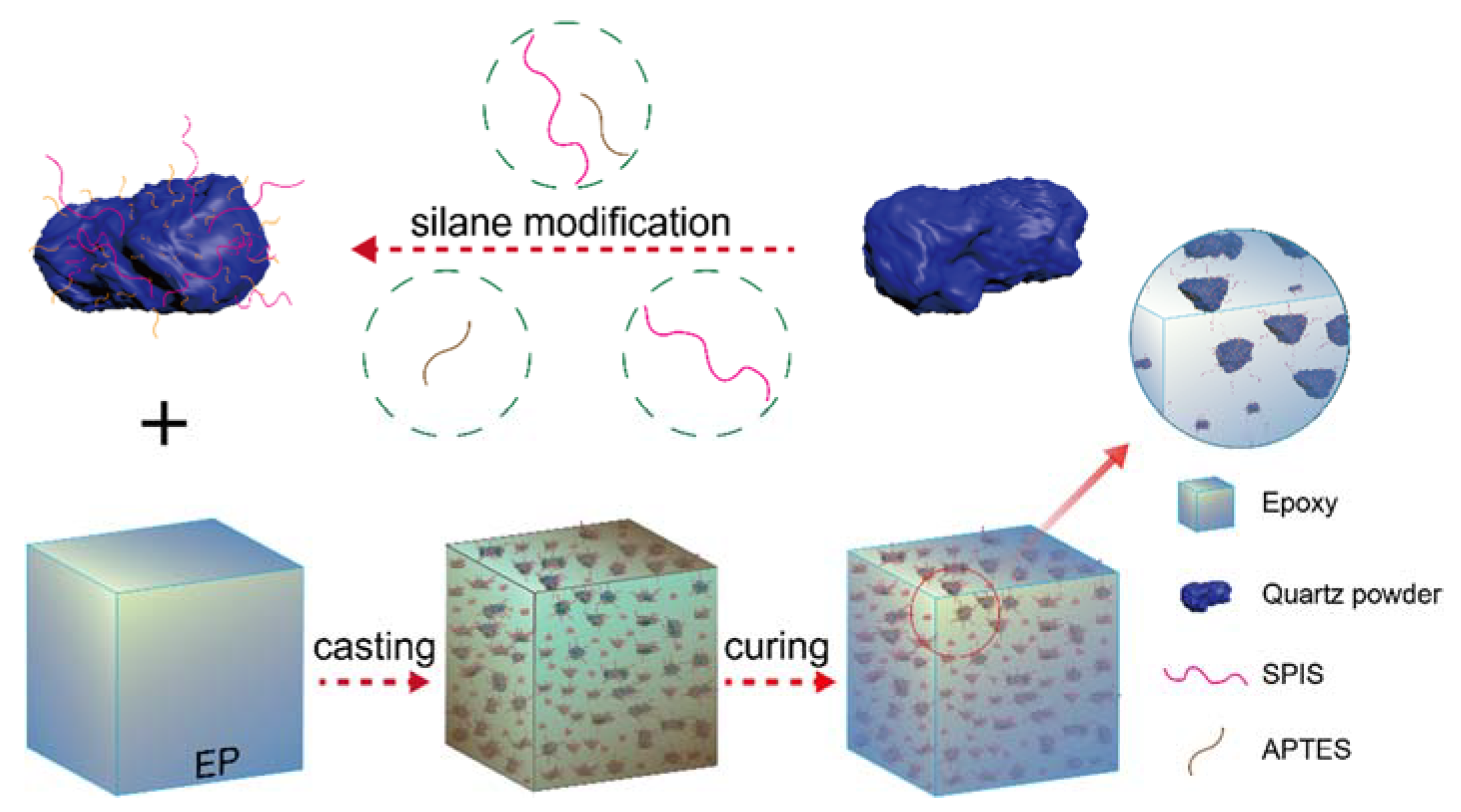
2.2.2. Fabrication of the QP–EP Composites

The EP and QP were placed in an oven at 70 °C for 30 min, and the EP, curing agent, and QP were gently mixed in a mass ratio of 1:1:2. This mixed powder was degassed in a vacuum oven at 70 °C for 20 min; then, it was poured into a mold to be pre-cured at 150 °C for 2 h and post-cured at 150 °C for 8 h in the oven. Afterward, the samples were naturally cooled to 25 °C. The preparation of the QP–EP composites is also illustrated in Figure 2.

2.2.3. Characterization

Fourier-transform infrared (FTIR; IRaffinity-1S, Shimazu Co, Ltd., Kyoto, Japan) spectroscopy was performed to determine the functional groups introduced on the QP surface. X-ray photoelectron spectroscopy (XPS; Escalab 250Xi, Thermo Fisher Scientific, Waltham, MA, USA) was performed to detect the chemical states and composition of the prepared composites. Furthermore, thermogravimetric analysis (TGA; STA499F5, NETZSCH-Gerätebau GmbH, Selb, Germany) was conducted to test the thermodynamic properties of the pristine and modified QPs.
Scanning electron microscopy (SEM; Nova Nano SEM 450, FEI Co, Hillsboro, OR, USA) was employed to investigate the dispersibility of the QPs (alone and in the EP matrix). The particle size distribution of particles was measured on the analyzer of Malvern Coulter (MS-3000, Malvern Panalytical Ltd., Malvern, UK). The shear viscosity of the EP/QP composites was measured using a Brookfield viscometer (DV-2T, Brookfield Co., Ltd. New York, NY, USA) at 70 °C, according to the ASTM 2396-86 standard, whereas their mechanical properties were evaluated using an electronic universal testing machine (AGS-X, Shimazu Co., Ltd., Kyoto, Japan) according to the GB/T 2567-2008 standard. The zeta potential of the surface-modified QPs was characterized via dynamic light scattering (DLS; Malvern ZetasizerNano ZS Instrument, Malvern Panalytical Ltd., Malvern, UK). For each DLS measurement, a 0.1 mg QP sample was sonicated for 3 min in 1 L of deionized water; then, 1 mL of the prepared suspension was used for testing.
The contact angles of the QPs and EP were conducted by a JC2000D contact angle measuring instrument (Shanghai Powerach Digital Technology Equipment Co. Ltd., Shanghai, China). The QPs before and after modification were compressed at 6.5 Mpa for 2 min to obtain a cylinder with a diameter of 10 mm and thickness of 1.5 mm. The measurements were performed in a sessile drop mold, and water and diiodomethane were used as the wetting solvents.

2.2.4. Estimation of Interfacial Energy

In order to calculate the interfacial energy between the filler and polymer, their surface energy at the mixing temperature needs to be known in advance, as well as the dispersive and polar components of the surface energy. First, the Owen–Wendt method [29] (Equations (1) and (2)) was adopted to acquire the surface energy by using the results of the contact angle measurement; then, the Guggenheim empirical formula [30] (Equation (3)) was used to calculate the surface energy at the mixing temperature, and finally, the interfacial energy was calculated through the harmonic mean equation [31] (Equation (4)).
γ S = γ S D + γ S D
γ L ( 1 + cos θ ) = 2 γ S D γ L D + 2 γ S P γ L P
where γ S represents the surface energy of the solid that needs to be acquired, and γ L represents the surface energy of the chosen liquid that is used to calculate the surface energy of the solid, and the superscripts of D and P represent the dispersive and polar components of the surface energy.
γ S , T M = γ S , T 0 ( 1 T 0 T M ) 11 / 9
where γ S ,   T 0 represents the known surface energy at the tested temperature, and γ S ,   T M represents the unknown surface energy of the target temperature.
γ 12 = γ 1 + γ 2 4 ( γ 1 D γ 2 D γ 1 D + γ 2 D + γ 1 P γ 2 P γ 1 P + γ 2 P )
where γ 1 or γ 2 represent the surface energy of the two components in contact, and γ 12 represents the calculated interfacial energy.

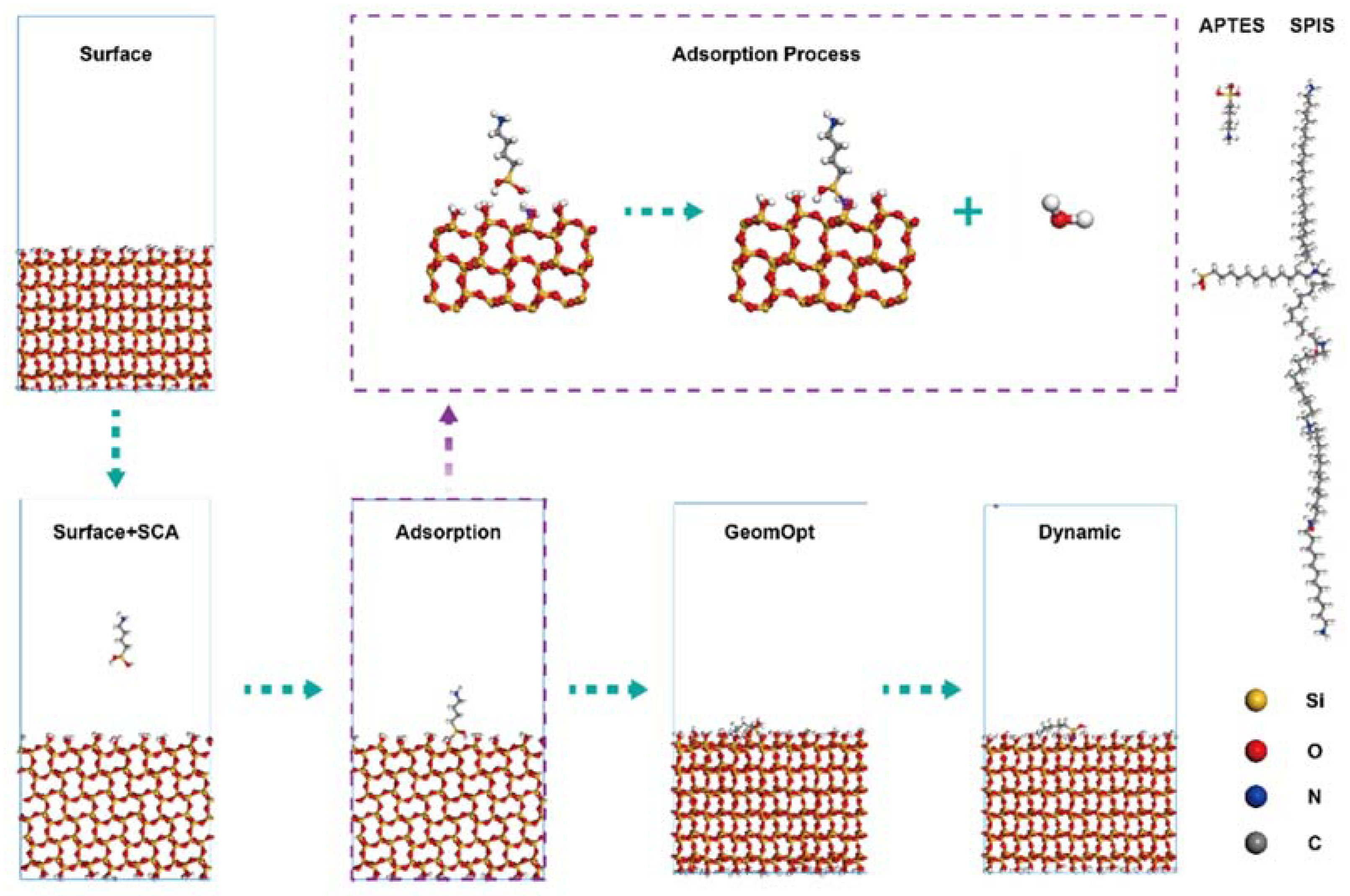
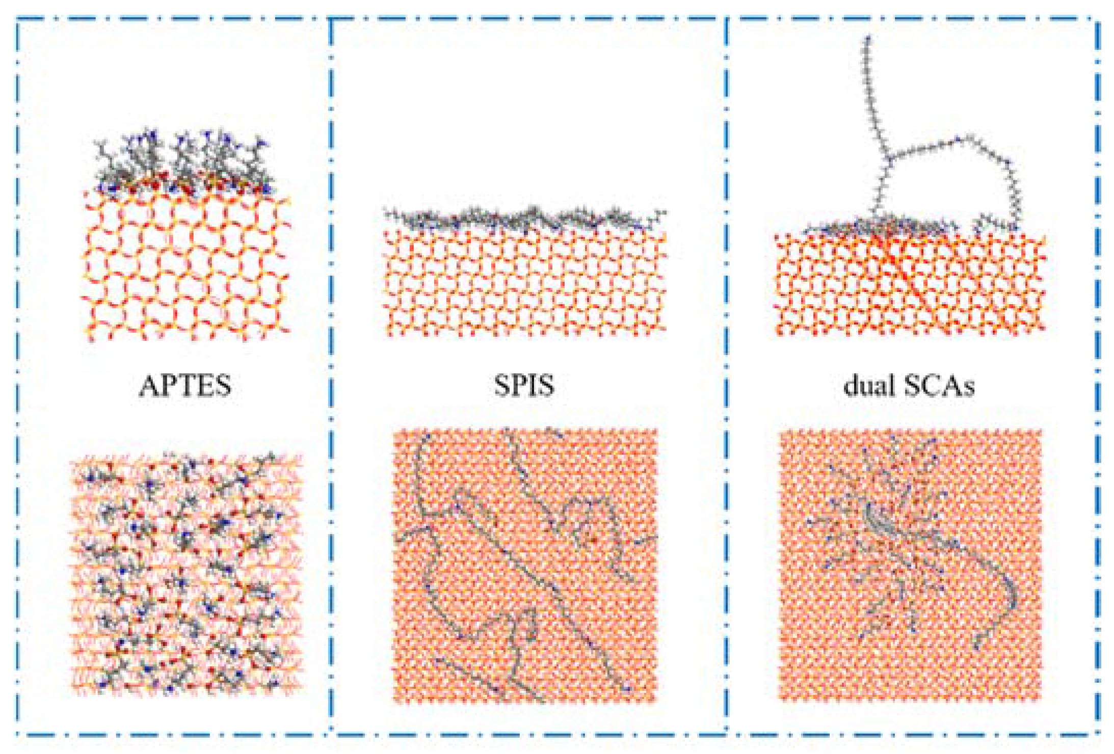
2.2.5. Molecular Dynamics Simulation

The molecular dynamics (MD) simulations were carried out by using the Forcite module incorporated in the Materials Studio 2021 (Accerlys software, San Diego, CA, USA). Three surface modules were constructed to study the adsorption characteristics of different SCAs. In this study, the quartz surface model (silica_Q3_4_7OH_5pct_ion) proposed by Emami et al. [32] was adopted. For APTES, the surface model was used without any further modification, and it was extended to a (2 × 2) supercell with a 140 Å vacuum slab above the modeled surface for the simulation of SPIS and the dual SCAs. The structural models of APTES and SPIS, along with the MD simulation of the SCAs, are shown in Figure 3. Moreover, the SCAs in the model were manually bonded to the quartz surface. For each simulation box, the MD simulations with a velocity scale thermostat of the NVT ensemble were used; the simulation time was 30 ps with a time step of 1 fs. A smart algorithm was used for the geometry optimization; the convergence thresholds for the energy, force, and displacement were set to 1 × 10⁻⁴ kcal·mol−1, 0.005 kcal·mol−1·Å−1, and 5.0 × 10⁻⁵ Å, respectively; and the COMPASS II [33] force field was adopted. Furthermore, the atom-based and Ewald [34] summation methods were adopted for the calculation of the van der Waals force and electrostatic energy. The cutoff distance for the van der Waals force was set to 15.5 Å, and the Ewald accuracy was set to 1 × 10⁻⁴ kcal/mol.

3. Results and Discussion

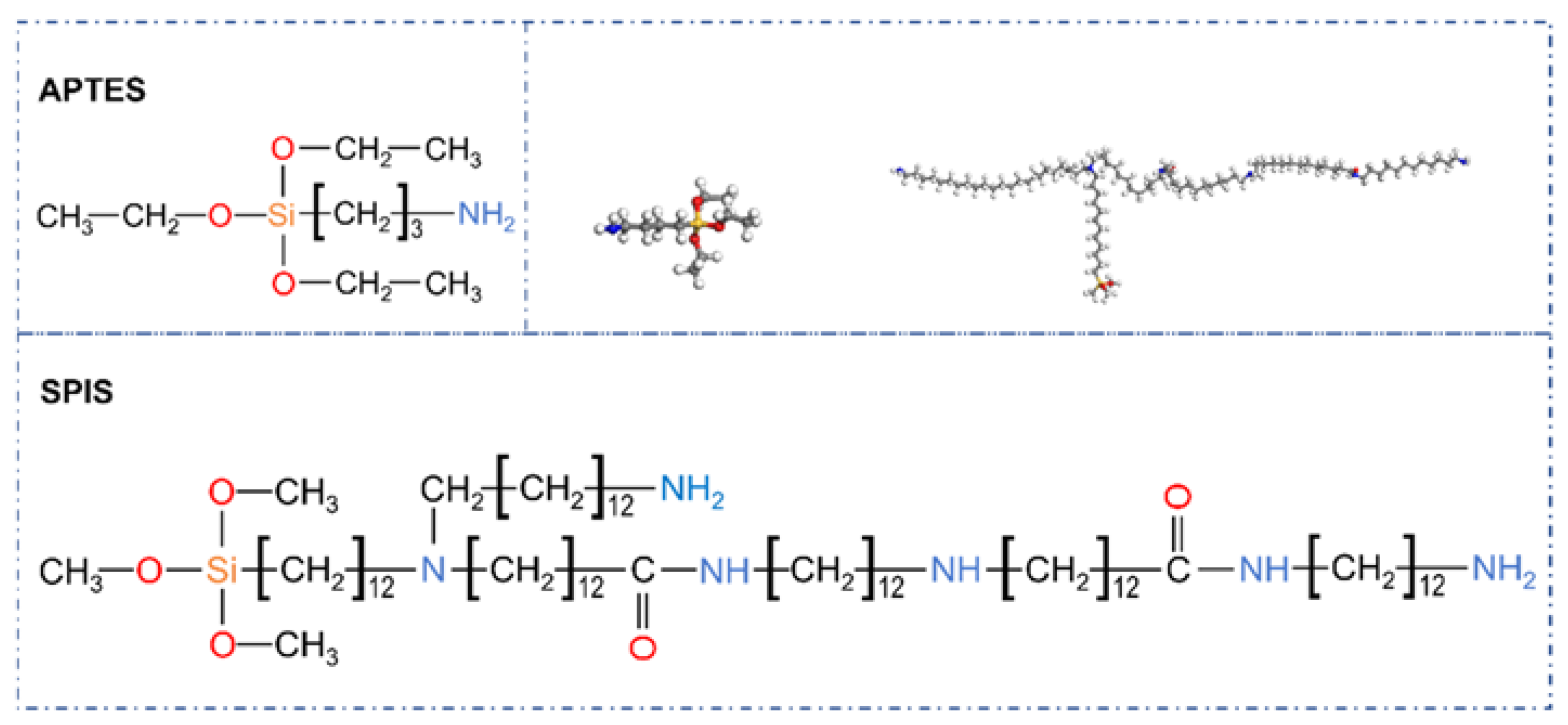
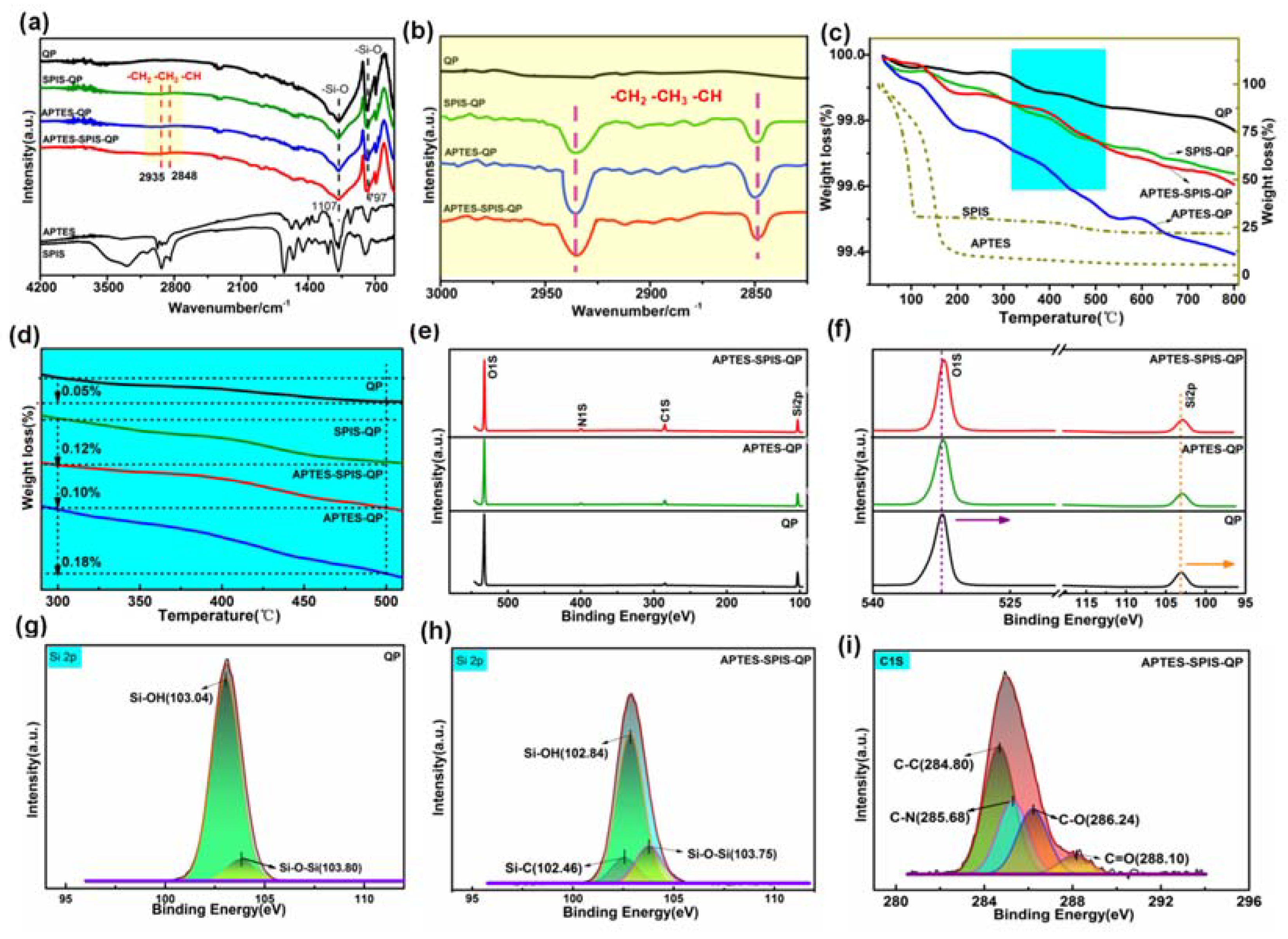
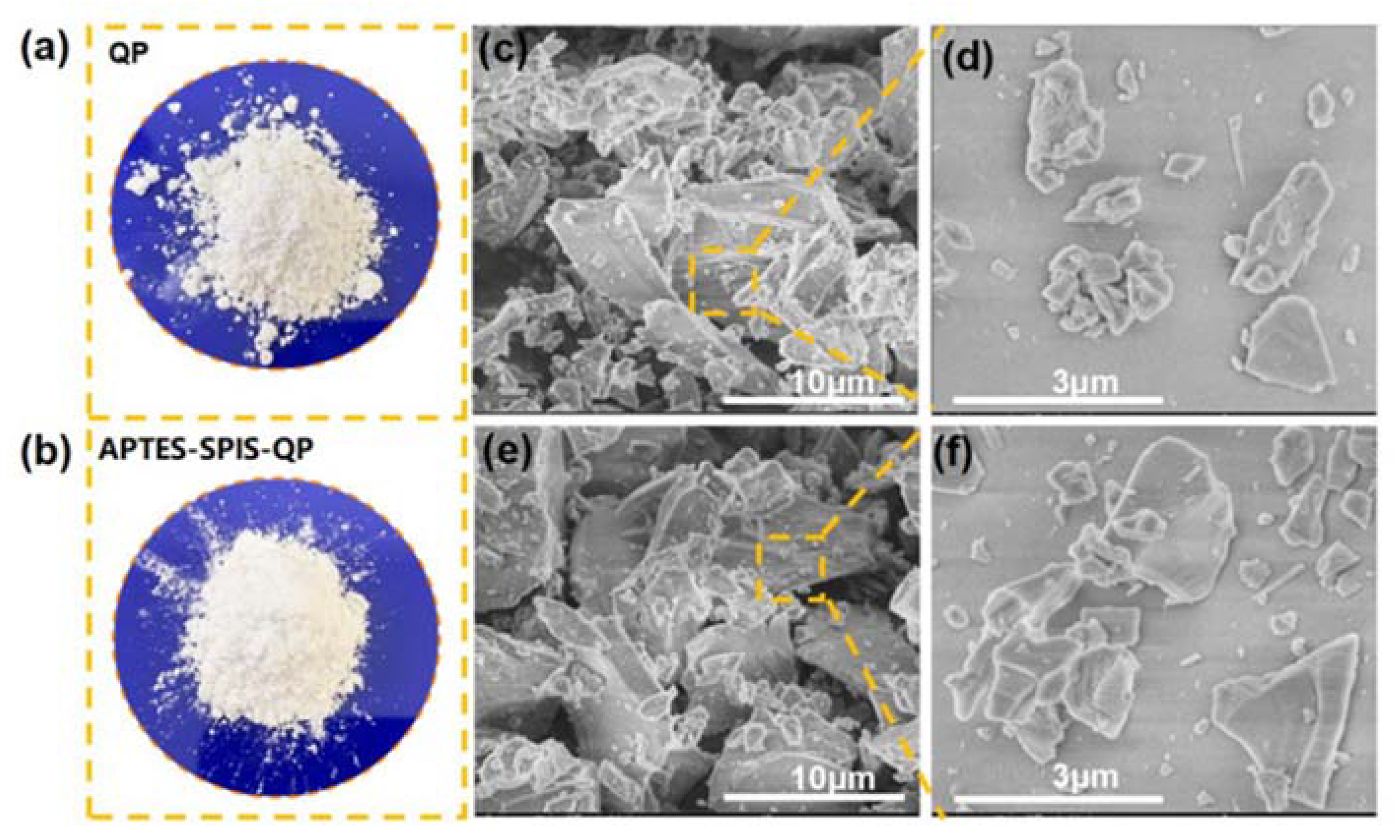
3.1. Surface Modification of QP with Single and Dual SCAs

The FTIR spectra were used to characterize the functional groups introduced to the QP surface (Figure 4a, b). For the pristine and SCA-treated QPs, the FTIR spectra exhibited peaks at approximately 1107 and 797 cm−1, respectively, which were typical peaks that could be attributed to the asymmetric stretching vibration and deformation vibration of Si–O–Si. In contrast to the pristine QP, the SCA-treated QP spectrum exhibited two peaks centered at 2935 and 2848 cm−1, which was attributed to the asymmetric and symmetric stretching vibrations of C–H, respectively, indicating the successful attachment of the SCAs to the QP surface [35].
Furthermore, TGA was used to examine the extent of SCA grafting on the QP surface and the thermal stability of the QP before and after the SCA treatment, and the corresponding results are shown in Figure 4c, d. For the SCA, more than 75% of the weight loss occurred within the temperature range of 50–200 °C, and the rate of weight loss slowed down beyond 200 °C. Compared to the SCA-treated QP, the untreated QP exhibited less weight loss within the whole temperature range, further proving the grafting of SCAs on the quartz surface. Notably, the QP modified by SPIS exhibited a negligible weight loss compared to that modified by APTES, implying that the quantity of APTES adsorbed to the quartz surface was more than that of the SPIS. The difference in the adsorption quantity was originally decided by their structures. The SPIS had a large molecular weight; it could occupy more surface area and prevent the adsorption of other molecules. Moreover, the amount of dual SCAs adsorbed on the QP surface was intermediate between APTES and SPIS, i.e., smaller than APTES and larger relative to the amount of adsorbed SPIS.
The XPS analysis was performed to examine the surface states and compositions of the as-obtained QP samples. The typical survey and high-resolution spectra are presented in Figure 4e, f. For the pristine QP, three main peaks located at 103.09, 284.80, and 532.44 eV were obtained, which could be attributed to Si 2p, C 1s, and O 1s at the quartz surface, respectively. C was possibly introduced by hydrocarbon contamination or CO2 adsorption from the ambient environment [36]. After the SCA treatment, a new peak appeared at ~400 eV, which belonged to N 1s. Furthermore, both the peak intensity and binding energy of Si 2p, C 1s, and O 1s exhibited a notable change. The C 1s spectrum of the modified sample (Figure 4i) contained four overlapping peaks, among which, one characteristic peak at 284.8 eV was assigned to the C–C bond, whereas the other three peaks at 285.68, 286.24, and 288.10 eV can be attributed to the C–N, C–O, and C–N bonds, respectively [35]. These results indicate that the SCA molecules bonded well to the quartz surface.
Notably, the main fitted peaks of Si 2p and O 1s of the modified samples shifted to lower binding energies compared with those of the pristine sample. For the O–H bond in the alcohol group, electrons would be closer to O because of the high electronegativity of O. After the SCA treatment, the bonded H was replaced by Si on the SCA. Si is more electronegative than H; thus, unlike the alcohol group, the bonding electrons are not attracted to O in this case, leading to the observed shift of the O 1s peaks to lower binding energies [37]. The Si 2p spectrum of the pristine sample was well-fitted by three peaks (Figure 4g), with binding energies of 103.04 and 103.80 eV for the Si–OH and Si–O–Si bonds, respectively [38]. For the modified QPs, a new peak corresponding to the Si–C bond was observed, primarily originating from the Si–C bond in the SCA molecules (Figure 4h). Compared to the pristine sample, the Si–O–Si peak of the SCA-treated sample shifted to a lower binding energy, suggesting the strong chemical adsorption of SCAs on the QP surface [39]. Furthermore, hydroxyl is an electron-donating group, which may also have caused the binding energy shift of Si 2p toward a lower energy [40]. Owing to the reaction of SCA with –OH, the amount of –OH decreased significantly, yielding a weakly intense Si–OH peak, which resulted in a shift toward lower binding energies [41].
The morphology of the pristine QP and the dual SCA-modified samples were characterized by SEM (Figure 5), and the average particle size of the as-obtained QP samples are presented in Table 1. The pristine particle exhibited conspicuous accumulation and aggregation. In contrast, the modified QP fine particles showed good dispersibility and reduced adhesion to each other. These results indicate that incorporating SCA reduces the particle aggregation of QP. All the SCAs could reduce the average particle size of the QP, and the QP samples modified by dual SCAs exhibited the smallest particle size.

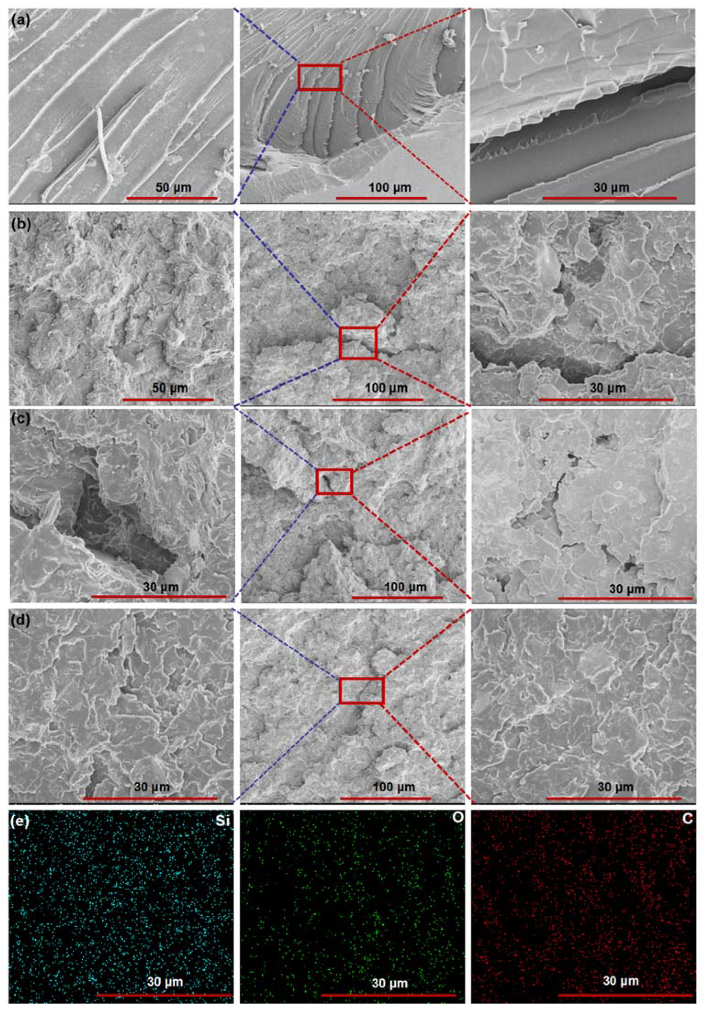
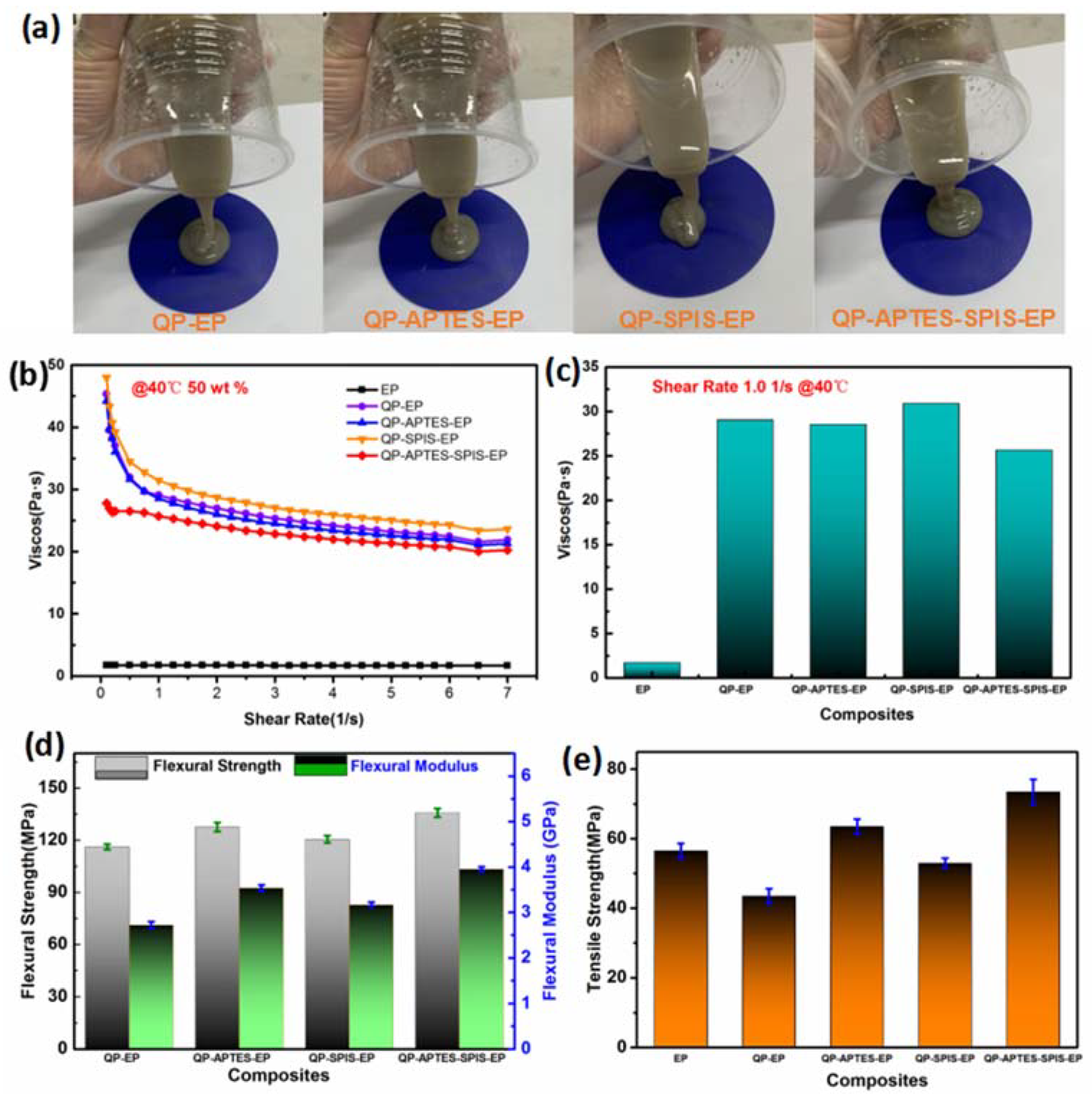
3.2. Dispersion and Performance of QP–EP Composites

According to the wetting theory of composites, the wetting of the filler by polymers is the primary condition for the adhesion to occur, so the contact angle of the QPs and EP was measured to predict their compatibility. The Owen–Wendt method, based on contact angle measurement, has been proven to be an effective way to estimate the surface energy, thus predicting the compatibility of fillers and polymers through interfacial energy [42], and a smaller interfacial energy means a better compatibility [43,44], which means the filler will disperse more evenly in the polymer matrix. The results of the contact angle measurement, as well as the derived surface energy and interfacial energy, are shown in Table 2. Among the SCAs used, the interfacial energy between the EP and dual SCAs-modified QP had the minimum value (15.72 mJ/m2), which was much lower than the interfacial energy between EP and QP that modified by APTES or SPIS (21.64 mJ/m2 for APTES and 25.64 mJ/m2 for SPIS). The estimated interfacial energy predicated that the dual SCA-modified QP had the best compatibility with EP, which also indicated that the dual SCAs grafted on the QP surface had a stronger interfacial adhesion with the EP matrix. Additionally, for the two components of the dual SCAs, short-chain APTES had a better compatibility with EP than long-chain SPIS. Based on the results of average particle size and the estimated interfacial energy, it could be inferred that dual SCA-modified QP would disperse more evenly in an EP matrix than single SCA, and its composites would also show a better performance.
To directly characterize the dispersion of modified QP in an EP matrix, SEM was carried out on the composites with different SCA-modified QPs, and the SEM micrographs of the fractured surfaces of the QP–EP composites are shown in Figure 6. Evidently, the fractured crack of pure EP (Figure 6a) was a smooth and straight glassy fractured surface, with cracks in different planes, and contained large fragments pulled out from the fractured surface. The morphology indicated that when the material was subjected to external forces, its internal crack development progressed almost unhindered because of the brittle fracture, which resulted in its poor mechanical strength [26]. After the composition of QP and EP, the fractured surfaces of the QP–EP composites were tougher, more irregular, and more divergent because of the incorporation of QP in the EP matrix (Figure 6b–d). Additionally, the fractured surfaces of the QP–EP composites with modified QP were very smooth, homogeneous, and possessed fewer holes and layers (Figure 6c and Figure 7d). This indicates that the SCA modification can effectively improve the dispersion of QP in an EP matrix. In particular, the EP matrix with dual SCA-modified QP (Figure 6d) showed the best fractured surface, revealing that the dual SCA-modified QP was evenly distributed in the EP matrix and exhibited the best compatibility with the matrix [45]. Figure 6e shows the EDS map of the dual SCA–QP–EP composites; the uniform distribution of Si, O, and C on the fractured surfaces confirmed that the QP particles were homogeneously dispersed in the EP matrix [46] (Figure 6e). What could be concluded and confirmed was that the dual SCA-modified QP had the best compatibility with EP, as well as the best dispersity.
Usually, the state of filler dispersion and interface interaction between the filler and the matrix are closely related to the rheological properties of polymer composites [47]. Moreover, a low viscosity is very helpful for the subsequent electronic packaging process [48,49]. The effects of different SCAs on the shear viscosity of the EP composites under 50 wt.% filler loading at 40 °C are shown in Figure 7a–c. The variation in the viscosity suggested that all the samples exhibited a shear-thinning behavior, which was similar with non-Newtonian fluids. The load of QP significantly influenced the streamline of the EP, and the friction between the QP and the EP matrix resulted in a large anelasticity, such that all the QP–EP composites exhibited higher viscosities than that of the pure EP [50].
In addition, compared to the modified samples, the pristine QP sample exhibited a higher viscosity over the entire testing range, except the single SPIS. Furthermore, among the SCAs used, the dual SCA modification resulted in the best rheological behavior, reducing the viscosity by 11.70% compared to that of the untreated QP–EP composites. This phenomenon was related to the dispersion of QP in the EP matrix and the interfacial adhesion between the QP and the EP. The decrease in the viscosity of the EP with the SCA-modified QP was possibly caused by a better dispersion of QP in the EP matrix than with the unmodified QP, which reduced the friction. Additionally, the increased viscosity of the single SPIS possibly originated from the combined effect of bad dispersion and a large interfacial adhesion, which resulted from the long alkyl chain that SPIS induced enhancing the interaction between the filler and matrix [51,52]. The viscosity test further proved that the dual SCA treatment effectively dispersed the QP in the EP matrix.
The effect of the single and dual SCA treatments on the flexural and tensile properties of the QP–EP composites is depicted in Figure 7d, e. All the composites showed mechanical properties superior to those of pure EP, thereby confirming that the introduction of QP was an effective process to improve the EP properties. Such an improvement was caused by a network generated by the dispersed QP. Furthermore, it could be seen that the flexural and tensile strengths of the EP with the SCA-modified QP were higher than those of the EP with untreated QP [53,54]. Compared to the untreated QP–EP composites, those treated with dual SCAs exhibited 16.89% higher flexural strength and 30.01% higher tensile strength. The SCA modification of QP further promoted the dispersion. Additionally, during the curing process, the amino group of the SCA interacted with the EP matrix, and the carbonyl group also formed hydrogen bonds, thus increasing the interfacial adhesion between the QP and the EP matrix. Thus, the EP composites with modified QP showed better mechanical properties. Additionally, the order of the flexural and tensile strengths followed that of the average particle size of the SCA-modified QP. Thus, the better the aggregation reduction of QP during the SCA modification process, the better the mechanical performance. The consistency between the average size of the QP particles and the mechanical properties indicated that the dispersion of QP in the EP matrix may have been the main factor that influenced the performance of the QP–EP composites.

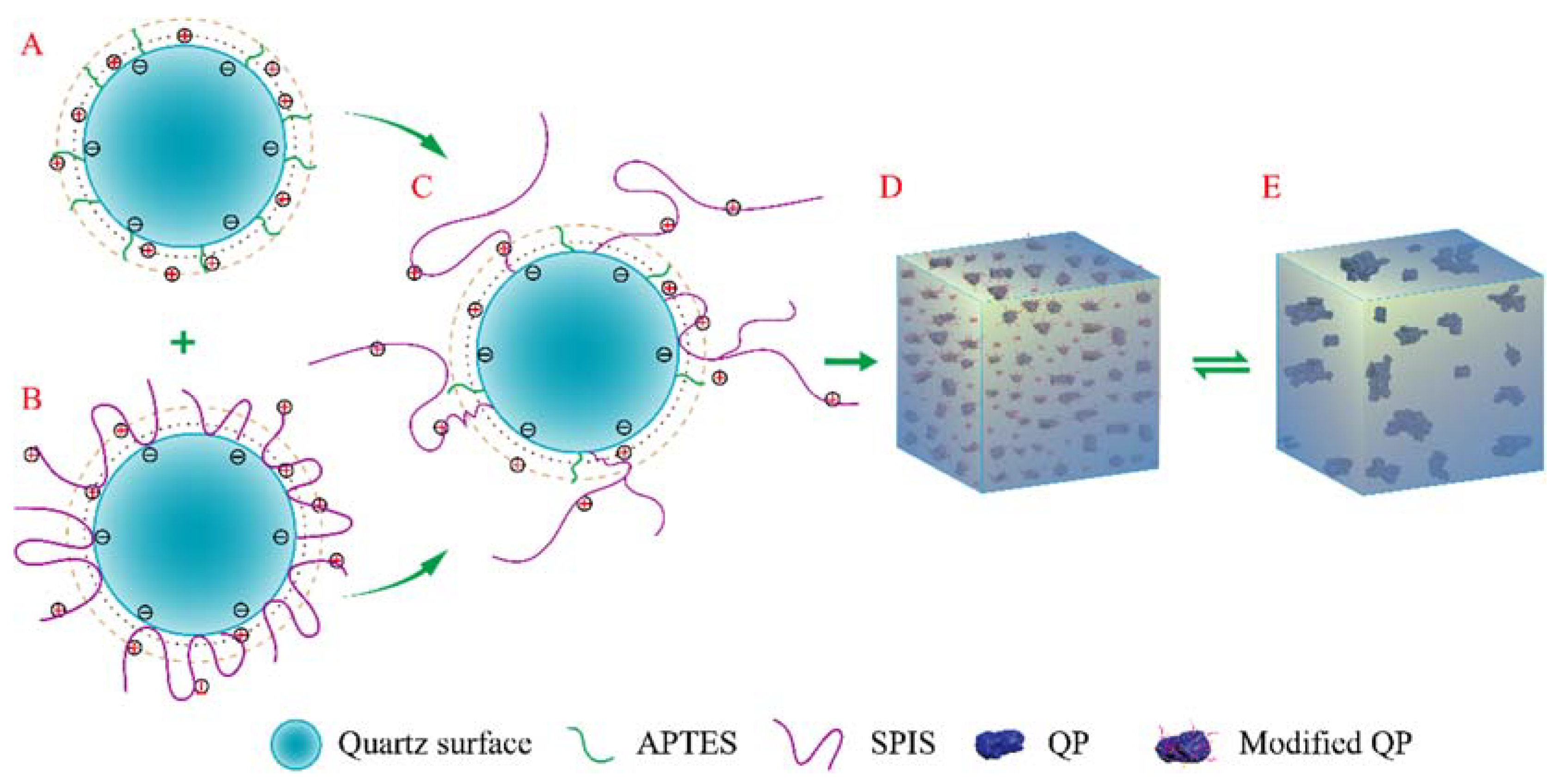
3.3. Dispersion Mechanism

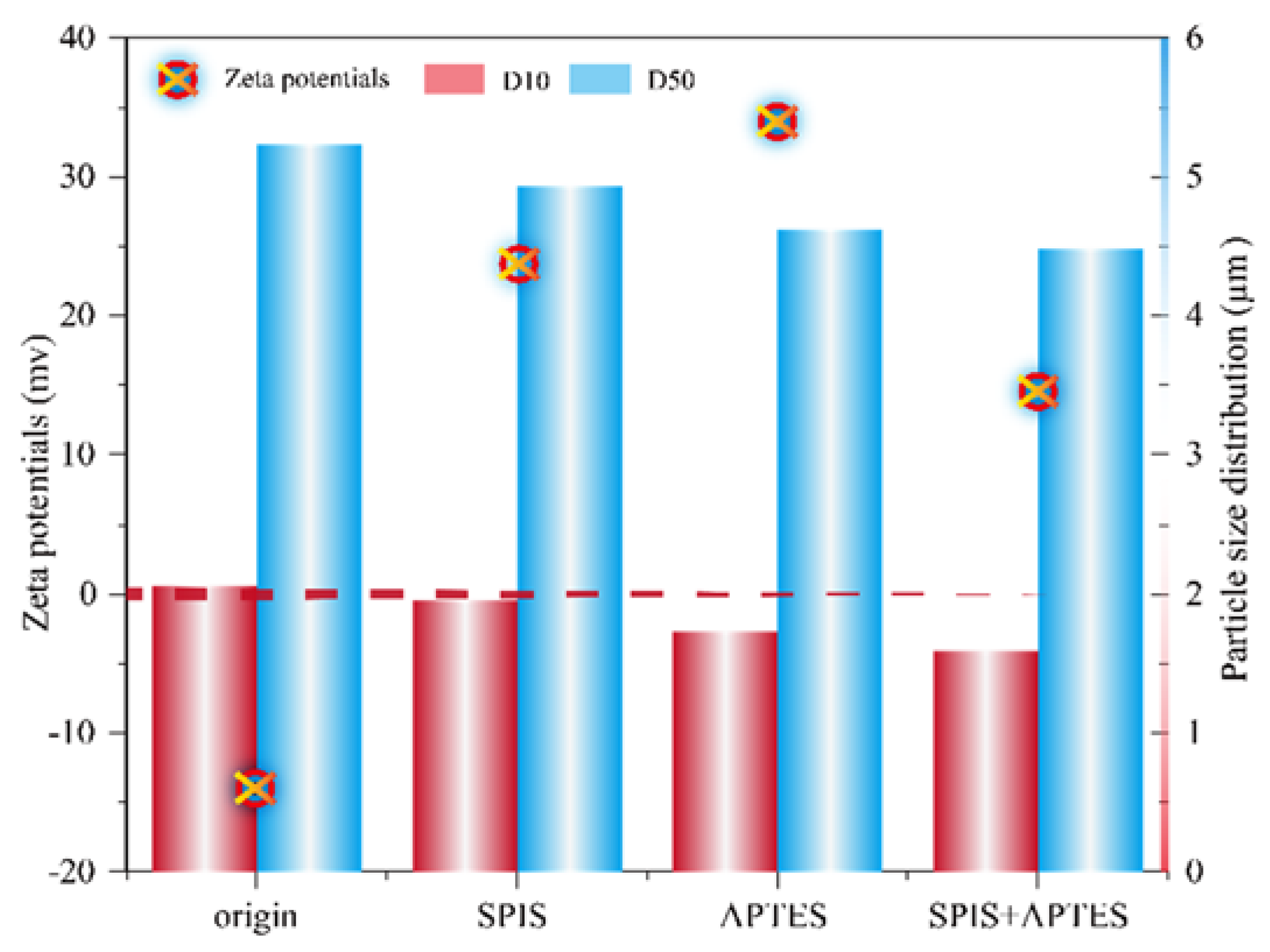
3.3.1. Aggregation Reduction of QP

For the SCAs used in this paper, the above results showed that better aggregation reduction means better dispersity in an EP matrix and mechanical properties. As for the interfacial adhesion, whether it also had a clear correlation remained unknown, so a zeta potential measurement was carried out to study the adsorption configuration and analysis the interfacial adhesion. Zeta potential provides a reference for the electronic force between particles, and a higher zeta potential of the same polarity indicates a higher electronic force and higher stability among the particles [55]. The zeta potential of the QPs treated with different SCAs and that of the pristine QP were measured, and the corresponding results are shown in Figure 8. The zeta potential of the pristine QP was negative (−14.25 mV), and its absolute value was insufficient to reduce the aggregation of the QP. The average particle size and zeta potential of the APTES-modified QP were 4.62 μm and 33.96 mV, respectively. Compared to the APTES, the SPIS-modified QP had a 32.27% lower zeta potential and 6.71% higher average particle size. In the case of the dual SCAs, the dual SCAs decreased the average particle size of the QP by 3.03% and decreased the average zeta potential by 57.24% compared to APTES. After the SCA modification, the potential changed from negative to positive, which could be attributed to the positively charged amino group in the SCA molecule. For the single SCA, a higher electrostatic force exhibited a better dispersion; hence, the electrostatic repulsion seems to play a key role in the dispersion of QP. However, SPIS is a high-molecular-weight compound, and the aggregation of QP may be improved by its steric hindrance stabilizing effect. However, the results indicated that the steric hindrance stabilization effect was constrained. The dual SCA-modified QP showed a better dispersion result with a smaller zeta potential, which means the steric hindrance stabilization effect of SPIS appeared again by using the dual SCAs. The dual SCAs could produce the best dispersion with the lowest zeta potential; thus, the steric hindrance effect must play a dominant role for dual SCAs, and the steric effect of SPIS might be influenced by APTES. The zeta potential and average size analysis indicated that the mixture of dual SCAs produced a better dispersion of the QP, exhibiting a synergistic effect between the SCAs.
To verify the effect of space steric hindrance stabilization on the reduction of aggregation, three surface models were constructed to simulate the aggregation and adsorption configuration of the SCAs on the quartz surface. In the first surface model, only APTES was considered, whereas in the second model, only the SPIS was adopted. In the third model, both these SCAs (dual SCAs) were included. The ratio of APTES and SPIS in the dual SCA model was the same as it was used in the experiment. Figure 9 shows the stable adsorption configuration extracted from the molecular dynamics simulation. When the surface was treated by SPIS (through a silanol reaction), the SPIS molecule remained on the surface, and an electrostatic attraction existed between the quartz surface and the amino group in the SPIS molecule (Figure 9, SPIS). Thus, the space steric hindrance stabilization effect could not be totally utilized because of this electrostatic attraction. This configuration explained that the SPIS-modified QP had a lower zeta potential and larger particle size at the same time. When both the APTES and SPIS were introduced simultaneously, the SPIS molecule stayed away from the quartz, and this configuration showed the best space steric hindrance stabilization effect. This was because the adsorbed APTES was able to prevent the total adsorption of SPIS on the quartz surface via the electrostatic repulsion between the positively charged amino groups of APTES and SPIS (Figure 9, Dual SCAs).

3.3.2. Dispersion Model–QP in EP Matrix

A schematic of the performance improvement mechanism of the QP–EP composites by dual SCAs is shown in Figure 10. The pristine QP was negatively charged in a slightly acidic environment and changed to positively charged after the SCA treatment (Figure 10a–c). The absolute value of the zeta potential also increased, indicating an increased stability. APTES was able to induce a stronger electronic repulsion force and a better dispersion, which was consistent with its action mechanism (Figure 10a). The SPIS molecule was totally adsorbed on the quartz surface because of the attractive force between the positively charged amino group in the SPIS and the negatively charged quartz surface (Figure 10b); thus, it showed a poor dispersion. Additionally, the adsorbed amino group could not play the SPIS’s advantage of long alkyl chains that could stretch into the EP matrix, generating a greater interfacial adhesion, neither could it introduce as much of the amino group as APTES, which meant fewer connections with the EP matrix, so the interfacial adhesion between the EP and SPIS-modified QP was smaller than that of the APTES. The dual SCAs yielded the best dispersion with the lowest electronic repulsion force because of the space steric hindrance stabilization effect. The adsorbed APTES prevented the adsorption of the amino group in the SPIS on the QP surface, thereby completely realizing the space steric hindrance stabilization effect of SPIS (Figure 10c). The dual SCAs significantly reduced the aggregation, thereby enabling an even distribution of the QP in the EP matrix (Figure 10d). The amino group and carbonyl group on the alkyl chains of SPIS stretched into and closely connected with the EP matrix, realizing the strong interfacial adhesion. Because of the enhanced dispersion of QP in the EP matrix and stronger interfacial adhesion, the EP exhibited a superior mechanical performance, including a relatively good rheological behavior, and an enhanced flexural strength and modulus.

4. Conclusions

By considering the aggregation reduction and interfacial compatibility at the same time, an efficient and economically designed dual SCA modification strategy of QP by adopting dual SCAs of different molecular weights (APTES and SPIS) was successfully proposed to improve its dispersion and interfacial adhesion, thus enhancing the performance of QP–EP composites. Different characterization methods proved that all SCAs could successfully graft on the quartz surface through chemical reactions, and the grafting structure was further explored through zeta potential measurement and molecular dynamics simulation. For the single SPIS, a totally adsorbed molecular chain limited its steric hindrance stabilization mechanism. However, the effect of SPIS in the dual SCAs was activated by electrostatic repulsion force from APTES; alone with the electrostatic stabilization mechanism, the dual SCAs have the best dispersion capacity. As can be seen (SEM) and measured (average particle size and contact angle measurement), dual SCA-modified QP has the least aggregation most effectively and had the best compatibility with EP. In addition, the adsorption configuration of the dual SCAs was more conducive for the amino and carbonyl groups of the SCA to interact with the EP matrix via chemical bonds and hydrogen bonds, thus strengthening the interfacial adhesion between the QP and EP matrix and improving the mechanical performance of the QP–EP composites. The as-prepared QP–EP composite exhibited an excellent performance with 11.70% lower viscosity, 16.89% higher flexural strength, and 30.01% higher tensile strength relative to the untreated QP–EP composites. This paper introduces a facile and extensible fabrication approach to design and remix modified agents based on molecular structures for potential industrial applications in the composites field.

Author Contributions

Conceptualization, P.L. and Z.R.; methodology, P.L., H.G. and Z.R.; software, Z.W. and E.X.; validation, L.M., H.G. and Z.R.; formal analysis, E.X. and L.X.; data curation, P.L. and X.Z.; writing—original draft preparation, P.L.; writing—review and editing, X.Z.; visualization, Z.W.; funding acquisition, P.L. and J.W. All authors have read and agreed to the published version of the manuscript.

Funding

This work was financially supported by the Key Research and Development Project of Anhui Province (CN) [202004a05020032] and Science and technology major special project of Anhui Province (CN) [201903a05020002].

Data Availability Statement

The raw/processed data required to reproduce these findings cannot be shared at this time due to technical or time limitations.

Acknowledgments

The authors thank Yuxiao Zhou for SEM measurements.

Conflicts of Interest

The authors declare no conflict of interest.

Abbreviations

QP, quartz powder; EP, epoxy resin; SCA, silane coupling reagent; APTES, 3-aminopropyl triethoxysilane; SPIS, silylated polyazamide silane; TGA, thermogravimetric analysis; XPS, X-ray photoelectron spectroscopy; SEM, scanning electron microscopy; MD, molecular dynamic simulation.

References

  1. Dong, R.; Wang, L.; Zhu, J. A novel SiO2–GO/acrylic resin nanocomposite: Fabrication, characterization and properties. Appl. Phys. A 2019, 125, 551. [Google Scholar] [CrossRef]
  2. Zhang, Z.; Ge, X.; Xing, R. Effects of different silane coupling agents on structure and properties of starch–chitosan–kaolin composites. J. Appl. Polym. Sci. 2019, 136, 48050. [Google Scholar] [CrossRef]
  3. Cheng, B.; Zhao, L.; Yu, J.; Zhao, X. Facile fabrication of SiO2/Al2O3 composite microspheres with a simple electrostatic attraction strategy. Mater. Res. Bull. 2008, 43, 714–722. [Google Scholar] [CrossRef]
  4. Baller, J.; Becker, N.; Ziehmer, M.; Thomassey, M.; Zielinski, B.; Muller, U.; Sanctuary, R. Interactions between silica nanoparticles and an epoxy resin before and during network formation. Polymer 2009, 50, 3211–3219. [Google Scholar] [CrossRef]
  5. Xing, J.; Deng, B.; Liu, Q. Effects if graphene nanoplatelets on the performance of polyphenylene sulfide composites produced by melt intercalation. High Perform. Polym. 2018, 30, 519–526. [Google Scholar] [CrossRef]
  6. Choi, S.; Kim, J. Thermal conductivity of epoxy composites with a binary-particle system of aluminum oxide and aluminum nitride filler. Compos. Part B Eng. 2013, 51, 140–147. [Google Scholar] [CrossRef]
  7. Smolka, M.G.; Wagenknecht, U.; Massadeh, S. The effect of silane-coated slag mineral on the mechanical and dynamic mechanical properties of unsaturated polyester composite materials. J. Adhes. Sci. Technol. 2020, 34, 1609–1627. [Google Scholar] [CrossRef]
  8. Kim, H.; Kim, H.G.; Kim, S.; Kim, S.S. PDMS-silica composite membranes with silane coupling for propylene separation. J. Membr. Sci. 2009, 344, 211–218. [Google Scholar] [CrossRef]
  9. Li, S.H.; Lin, M.M.; Toprak, M.S.; Kim, D.K.; Muhammed, M. Nanocomposites of polymer and inorganic nanoparticles for optical and magnetic applications. Nano Rev. 2010, 1, 5214. [Google Scholar] [CrossRef]
  10. Saba, N.; Tahir, P.M.; Jawaid, M. A review on potentiality of nano filler/natural fiber filled polymer hybrid composites. Polymer 2014, 6, 2247–2273. [Google Scholar] [CrossRef]
  11. Jin, F.L.; Li, X.; Park, S.J. Synthesis and application of epoxy resins: A review. J. Ind. Eng. Chem. 2015, 29, 1–11. [Google Scholar] [CrossRef]
  12. Rong, M.Z.; Zhang, M.Q.; Ruan, W.H. Surface modification of nanoscale fillers for improving properties of polymer nanocomposites: A. review. Mater. Sci. Technol. 2006, 22, 787–796. [Google Scholar] [CrossRef]
  13. Azizah, A.B.; Rozman, H.D.; Azniwati, A.A.; Tay, G.S. The effect of filler loading and silane treatment on kenaf core reinforced polyurethane composites: Mechanical and thermal properties. J. Polym. Environ. 2020, 28, 517–531. [Google Scholar] [CrossRef]
  14. Aziz, T.; Ullah, A.; Fan, H.; Jamil, M.I.; Khan, F.U.; Ullah, R.; Iqbal, M.; Ali, A.; Ullah, B. Recent Progress in Silane Coupling Agent with Its Emerging Applications. J. Polym. Environ. 2021, 29, 3427–3443. [Google Scholar] [CrossRef]
  15. Kango, S.; Kalia, S.; Celli, A.; Njuguna, J.; Habibi, Y.; Kumar, R. Surface modification of inorganic nanoparticles for development of organic–inorganic nanocomposites: A review. Process Polym. Sci. 2013, 38, 1232–1261. [Google Scholar] [CrossRef]
  16. Iijima, M.; Tsukada, M.; Kamiya, H. Effect of particle size on surface modification of silica nanoparticles by using silane coupling agents and their dispersion stability in methylethylketone. J. Colloid Interface Sci. 2007, 307, 418–424. [Google Scholar] [CrossRef]
  17. Xie, Y.; Hill, C.A.S.; Xiao, Z.; Militz, H.; Mai, C. Silane coupling agents used for natural fiber/polymer composites: A review. Compos. Part A Appl. Sci. Manuf. 2010, 41, 806–819. [Google Scholar] [CrossRef]
  18. Song, J.; Dai, Z.D.; Li, J.Y.; Zhao, H.C.; Wang, L.P. Silane coupling agent modified BN-OH as reinforcing filler for epoxy nanocomposite, High Perform. Polymers 2019, 31, 116–123. [Google Scholar] [CrossRef]
  19. Shokoohi, S.; Arefazer, A.; Khosrokhavar, R. Silane Coupling Agents in Polymer-based Reinforced Composites: A Review. J. Reinf. Plast. Compos. 2008, 27, 473–485. [Google Scholar] [CrossRef]
  20. Werner, R.; Krysztafkiewicz, A.; Jesionowski, T.; Jeczalik, J. Silane-modified sodium-aluminium silicates-fillers used in polyurethane elastomers. J. Adhes. Sci. Technol. 2012, 15, 1711–1724. [Google Scholar] [CrossRef]
  21. Jesionowski, T.; Krysztafkiewicz, A. Silicas modified with amino-and mercaptosilanes-fillers of urethane elastomers. Compos Interface 2012, 8, 243–248. [Google Scholar] [CrossRef]
  22. Hewitt, N. Compounding Precipitated Silica in Elastomers: Theory and Practice; William Andrew: Norwich, NY, USA, 2007. [Google Scholar]
  23. Muhamad, M.S.; Salim, M.R.; Lau, W.J. Surface modification of SiO2 nanoparticles and its impact on the properties of PES-based hollow fiber membrane. RSC Adv. 2015, 5, 58644–58654. [Google Scholar] [CrossRef] [Green Version]
  24. Hao, L.F.; Gao, T.T.; Xu, W.; Wang, X.C.; Yang, Q.S.; Liu, X.G. Preparation of crosslinked polysiloxane/SiO2 nanocomposite via in-situ condensation and its surface modification on cotton fabrics. Appl. Surf. Sci. 2016, 371, 281–288. [Google Scholar] [CrossRef]
  25. Yu, S.; Oh, K.H.; Hwang, J.Y.; Hong, S.H. The effect of amino-silane coupling agents having different molecular structures on the mechanical properties of basalt fiber-reinforced polyamide 6,6 composites. Compos. Part B Eng. 2019, 163, 511–521. [Google Scholar] [CrossRef]
  26. Wang, H.Y.; Sun, T.; Peng, C.; Wu, Z.J. Effect of different silane coupling agents on cryogenic properties of silica-reinforced epoxy composites. J. Index. Metr. 2016, 30, 24–37. [Google Scholar] [CrossRef] [Green Version]
  27. Mallakpour, S.; Madani, M. The effect of the coupling agents KH550 and KH570 on the nanostructure and interfacial interaction of zinc oxide/chiral poly(amide–imide) nanocomposites containing L-leucine amino acid moieties. J. Mater. Sci. 2014, 49, 5112–5118. [Google Scholar] [CrossRef]
  28. Mori, T.; Okada, Y.; Kamiya, H. Effect of surface modification of silica particles on interaction forces and dispersibility in suspension. Adv. Powder Technol. 2016, 27, 830–838. [Google Scholar] [CrossRef]
  29. Owens, D.K.; Wendt, R.C. Estimation of the Surface Free Energy of Polymers. J. Appl. Polym. Sci. 1969, 13, 1741–1747. [Google Scholar] [CrossRef]
  30. Mao, Z.; Zhang, J. Largely improved the low temperature toughness of acrylonitrile-styrene-acrylate (ASA) resin: Fabricated a core-shell structure of two elastomers through the differences of interfacial tensions. Appl. Surf. Sci. 2018, 444, 345–354. [Google Scholar] [CrossRef]
  31. Mao, Z.; Sun, H.; Zhang, J. Selective distribution of SrTiO3 in co-continuous composites: An effective method to improve the dielectric and mechanical properties. Compos. Pt. A Appl. Sci. Manuf. 2021, 143, 106312. [Google Scholar] [CrossRef]
  32. Emami, F.S.; Puddu, V.; Berry, R.J.; Varshney, V.; Patwardhan, S.V.; Perry, C.C.; Heinz, H. Force field and a surface model database for silica to simulate interfacial properties in atomic resolution. Chem. Mater. 2016, 26, 2647–2658. [Google Scholar] [CrossRef]
  33. Sun, H.; Jin, Z.; Yang, C.; Akkermans, R.; Robertson, S.; Spenley, N.; Miller, S.; Todd, S. COMPASS II: Extended coverage for polymer and drug-like molecule databases. J. Mol. Model. 2016, 22, 2647–2658. [Google Scholar] [CrossRef] [PubMed]
  34. Ewald, P.P. Die Berechnung optischer und elektrostatischer Gitterpotentiale. Ann. Phys. 1921, 369, 253–287. [Google Scholar] [CrossRef] [Green Version]
  35. Xu, G.; Xu, G.; Chang, W.; Wang, H. Fabrication of microsphere-like nano-MoO2 modified with silane coupling agent KH550. Mater. Res. Express 2019, 6, 115087–115094. [Google Scholar] [CrossRef]
  36. Wie, J.; Kim, M.; Kim, J. Enhanced thermal conductivity of a polysilazane-coated A-BN/epoxy composite following surface treatment with silane coupling agents. Appl. Surf. Sci. 2020, 529, 147091–147099. [Google Scholar] [CrossRef]
  37. Lin, P.; Pu, L.; Luan, M. Study on surface modification of natural power quartz by silane coupling agent KH-560. J. Heilongjiang Inst. Technol. 2012, 2, 9–11. [Google Scholar] [CrossRef]
  38. Luo, B.; Zhu, Y.; Sun, C.; Li, Y.; Han, Y. Flotation and adsorption of a new collector α-Bromodecanoic acid on quartz surface. Miner. Eng. 2015, 77, 86–92. [Google Scholar] [CrossRef]
  39. Yang, S.; Xu, Y.; Liu, C.; Soraya, D.; Li, C.; Li, H. Investigations on the synergistic effect of combined NaOl/SPA collector in ilmenite flotation. Colloid. Surf. A Physicochem. Eng. Asp. 2021, 628, 127267. [Google Scholar] [CrossRef]
  40. Wu, W.; Chen, J.Q.Y. Influence of the kinds and structure of silane coupling agent polymer grafting modification of the ultrafine silicon dioxide surface. J. Chin. Ceram. Soc. 2004, 5, 570–575. [Google Scholar] [CrossRef]
  41. Li, X.; Cao, Z.; Zhang, Z.; Dang, H. Surface-modification in situ of nano-SiO2 and its structure and tribological properties. Appl. Surf. Sci. 2006, 252, 7856–7861. [Google Scholar] [CrossRef]
  42. Tran, L.; Fuentes, C.; Dupont-Gillain, C.; van Vuure, A.; Verpoest, I. Understanding the interfacial compatibility and adhesion of natural coirfibre thermoplastic composites. Compos. Sci. Technol. 2013, 80, 23–30. [Google Scholar] [CrossRef]
  43. Rzeczkowski, P.; Krause, B.; Potschke, P. Characterization of Highly Filler PP/Graphite Composites for Adhesive Joining in Fuel Cell Applications. Polymers 2019, 11, 462. [Google Scholar] [CrossRef] [PubMed] [Green Version]
  44. Zhang, Q.; Wang, J.; Zhang, B.; Guo, B.; Yu, J.; Guo, Z. Improved electrical conductivity of polymer/carbon black composites by simultaneous dispersion and interaction-induced network assembly. Compos. Sci. Technol. 2019, 179, 106–114. [Google Scholar] [CrossRef]
  45. Xiao, C.; Li, D.; Zeng, D.; Lang, F.; Lin, Y. A comparative investigation on different silane coupling agents modified sericite mica/polyimide composites prepared by in situ polymerization. Polym. Bull. 2021, 78, 863–883. [Google Scholar] [CrossRef]
  46. Chen, C.; Wang, H.; Xue, Y.; Xue, Z.; Liu, H.; Xie, X.; Mai, Y. Structure, rheological, thermal conductive and electrical insulating properties of high-performance hybrid epoxy/nanosilica/AgNWs nanocomposites. Compos. Sci. Technol. 2016, 128, 207–214. [Google Scholar] [CrossRef] [Green Version]
  47. Chao, C.; Tang, Y.; Ye, Y.; Xue, Z.; Xue, Y.; Xie, X.; Mai, Y. High-performance epoxy/silica coated silver nanowire composites as underfill material for electronic packaging. Compos. Sci. Technol. 2014, 105, 80–85. [Google Scholar] [CrossRef]
  48. Hu, Y.; Chen, C.; Wen, Y.; Xue, Z.; Zhou, X.; Shi, D.; Hu, G.; Xie, X. Novel micro-nano epoxy composites for electronic packaging application: Balance of thermal conductivity and processability. Compos. Sci. Technol. 2021, 209, 108760. [Google Scholar] [CrossRef]
  49. Guo, Q.; Zhu, P.; Li, G.; Wen, J.; Wang, T.; Lu, D.; Sun, R.; Wong, C. Study on the effects of interfacial interaction on the rheological and thermal performance of silica nanoparticles reinforced epoxy nanocomposites. Compos. Part B 2017, 116, 388–397. [Google Scholar] [CrossRef]
  50. Rueda, M.; Auscher, M.; Fulchiron, R.; Périé, T.; Martin, G.; Sonntag, P.; Cassagnau, P. Rheology and applications of highly filled polymers: A review of current understanding. Prog. Polym. Sci. 2017, 66, 22–53. [Google Scholar] [CrossRef]
  51. Mishra, D.; Dehury, J.; Rout, L.; Satapathy, A. The effect of particle size, mixing conditions and agglomerates on thermal conductivity of BN-polyester and multi-sized BN-hybrid composites for use in micro-electronics. Mater. Today Proc. 2020, 26, 3187–3192. [Google Scholar] [CrossRef]
  52. Wu, W.; Cong, S. Silica and diatomite fillers modified fluorine rubber composites treated by silane-coupling agents. J. Vinyl Addit. Technol. 2019, 26, 55–61. [Google Scholar] [CrossRef]
  53. Wei, B.; Chang, Q.; Bao, C.; Dai, L.; Zhang, G. Surface modification of filter medium particles with silane coupling agent KH550. Colloid. Surf. A Physicochem. Eng. Asp. 2013, 434, 276–280. [Google Scholar] [CrossRef]
  54. Wang, L.; Tang, C.; Wang, X.; Zheng, W. Molecular dynamics simulation on the thermodynamic properties of insulating paper cellulose modified by silane coupling agent grafted nano-SiO2 cite. AIP Adv. 2019, 9, 125134. [Google Scholar] [CrossRef] [Green Version]
  55. Vallar, S.; Houivet, D.; el Fallah, J.; Kervadec, D.; Haussonne, J.M. Oxide slurries stability and powders dispersion: Optimization with zeta potential and rheological measurements. J. Eur. Ceram. Soc. 1999, 19, 1017–1021. [Google Scholar] [CrossRef]
Figure 1. Chemical structures of APTES and SPIS.
Minerals 12 00784 g001
Figure 2. Illustration of the QP–EP composite synthesis.
Minerals 12 00784 g002
Figure 3. MD simulation process of the SCAs.
Minerals 12 00784 g003
Figure 4. Surface coating analysis of the as-obtained samples. (a) FTIR spectra of the as-obtained samples. (b) Magnified images showing the absorption peaks of the organic functional groups, such as alkyl, –CH2, and –CH3 of the as-obtained samples. (c) TGA curves of the as-obtained samples. (d) Magnified TGA curves at 300–500 °C. (e) XPS spectra of the as-obtained samples. (f) Magnified spectra showing the O 1s and Si 2p peaks. (g) Si 2p spectrum of the pristine sample. (h) Si 2p spectrum of the sample modified by 2% APTES and 1% SPIS. (i) C 1s spectrum of APTES- and SPIS-modified sample.
Minerals 12 00784 g004
Figure 5. Morphology of the as-obtained samples. Photographs of the (a) pristine sample and those of (b) the samples modified by 2% APTES and 1% SPIS. SEM images of the (c,d) pristine sample and those of (e,f) the samples modified by 2% APTES and 1% SPIS.
Minerals 12 00784 g005
Figure 6. Morphology of the neat EP and its composites. Fractured surfaces of pure EP and QP–EP composites. (a) Pure EP; (b) QP–EP composites; (c) APTES–QP–EP composites; and (d) dual SCA–QP–EP composites. (e) Energy-dispersive spectroscopic mapping images of Si, O, and C on the QP–APTES–SPIS–EP composite surface.
Minerals 12 00784 g006
Figure 7. Mechanical properties of the neat EP and their composites. (a) Photographs of the flow properties of epoxy composites (b) Relationship between viscosity and shear rate. (c) Viscosity at a shear rate of 1.0 1/s. (d) Flexural strength and modulus. (e) Tensile strength.
Minerals 12 00784 g007
Figure 8. Average size and zeta potential of the surface-modified QP without and with the SCAs.
Minerals 12 00784 g008
Figure 9. Stable adsorption configuration of the different SCAs on quartz surface.
Minerals 12 00784 g009
Figure 10. Schematic showing the performance improvement mechanism of the QP–EP composites. (A) QP modified by APTES. (B) QP modified by SPIS. (C) QP modified by dual SCAs. (D) EP composites with dual SCAs modified QP. (E) EP composites with pristine QP.
Minerals 12 00784 g010
Table 1. D10 and D50 of the QP modified by different SCAs.
Sample NameD10/μmD50/μmD97/μm
Pristine QP2.065.2516.92
QP-SPIS1.964.9316.45
QP-APTES1.734.6216.31
QP-dual SCAs1.594.4815.92
Table 2. Measured contact angle and the calculated surface tension and interfacial tension.
SampleContact Angle (°)Surface Energy (70 °C, mJ/m2)Interfacial Energy
(mJ/m2)
H2OCH2I2γDγPγ
EP
QP
APTES
SPIS
Dual SCAs
109.00
27.25
38.60
27.25
53.50
83.00
42.50
36.50
22.50
33.50
10.12
18.43
21.07
24.05
23.32
0.52
25.15
19.29
21.46
11.98
10.64
43.58
40.36
45.51
35.30
-
26.06
21.64
25.64
15.72
Publisher’s Note: MDPI stays neutral with regard to jurisdictional claims in published maps and institutional affiliations.

