


A Simplified Model Predictive Control for Asymmetrical Six-Phase Induction Motors That Eliminates the Weighting Factor


CISE—Electromechatronic Systems Research Centre, University of Beira Interior, Calçada Fonte do Lameiro, P-6201-001 Covilhã, Portugal
*
Author to whom correspondence should be addressed.
Machines 2022, 10(12), 1189; https://doi.org/10.3390/machines10121189
Submission received: 31 October 2022
/
Revised: 3 December 2022
/
Accepted: 6 December 2022
/
Published: 8 December 2022
(This article belongs to the Special Issue Innovative Applications of Multiphase Machines)
Abstract
:The conventional model predictive control (MPC) is an attractive control scheme for the regulation of multiphase electric drives, since it easily exploits their inherent advantages. However, as the number of phases increases, the MPC’s complexity increases exponentially, posing a high computational burden. Additionally, the MPC still presents other issues related to the weighting factor design in the cost function. Accordingly, this paper proposes a low-complexity hysteresis model predictive current control (HMPCC) that can significantly reduce the computational burden, improve the motor’s performance, and completely avoid the weighting factor design. The proposed method is a hybrid control method, consisting of two distinct controls that complement one another. The hysteresis control is used to reduce the number of iterations per sampling period, thereby reducing the computational effort required to choose the voltage vector that actively produces torque/flux, and nullifying the weighting factor requirement. Finally, the MPC is used to improve the torque and current quality. The effectiveness of the proposed method is verified through experimental data, and the results emphasize the improvement of the proposed HMPCC scheme.
1. Introduction
Recently, the technological development of power electronic devices has allowed electric machines—especially multiphase machines—to become a potential solution for several industrial applications, such as the automotive industry, ship propulsion, and wind energy generation systems [1]. The appearance of such drives was motivated by the need for high-performance drive systems, which have rigorous levels of reliability, as an intrinsic advantage [2]. However, new challenges that need to be overcome have been highlighted by the scientific community. Therefore, work has been reported to address several challenges, such as high computational burden [3], reducing current harmonic distortion [4,5,6], parameter identification [7], fault detection, and post-fault operation [8].
In fact, multiphase machines present several advantages, with the main ones being higher degrees of freedom, post-fault reliability, and reduced current per phase [9]. However, the complexity and cost of the power converter also dramatically increase by where n is the number of phases, limiting their practical application. Among the multiphase machines, those with multiple three-phase windings (such as 6-phase, 9-phase, or 18-phase machines) are most frequently discussed. These machines have the benefits of all other multiphase machines but can use modular three-phase structures, providing an easier and cheaper transition from three-phase systems to multiphase systems [10].
The most researched configurations of multiphase machines in the literature are the six-phase machines. Nevertheless, the extension of the classic controls—from three-phase machines to multiphase machines—is not a straightforward process. In multiphase machines, it is necessary to control not only the flux/torque production (α-β subspace), but also the machine losses (x-y subspace). Hence, field-oriented control (FOC) with multiple inner proportional integer (PI) current controllers and direct torque control (DTC) [11] has been analyzed over the years. Moreover, model predictive control (MPC) has been one of the most popular control choices in the last decade. MPC has an inherent fast dynamic response as well as the capacity to easily include various control objectives when compared to classic linear controllers [11]. Usually, there are two types of MPC methods, namely, predictive current control (PCC) [12] and predictive torque control (PTC) [13]. However, PCC is most commonly used, so the research community has highlighted some challenges, especially when applied to multiphase machines. It is well known that the conventional PCC suffers from a heavy computational burden, since the available voltage vectors increase exponentially with the number of machine phases. In the case of asymmetrical six-phase motors fed by a six-phase two-level voltage source inverter (2L-VSI), there are control options, which means 64 different voltage vectors for regulation of the stator currents in six-phase machines. Therefore, the classic MPC, excluding redundant vectors, uses 49 voltage vectors to predict the future behavior of the power converters in each sampling period. The error between the predicted system outputs and their reference values is evaluated in the cost function. The voltage vector with the smallest error is then selected as the optimal control action and employed for the power converters in the subsequent sampling period, meaning that the classic MPC requires a high computational burden due to all of the combinations of voltage vectors being used in the prediction and evaluation stages [14]. The higher computational cost can be handled by either increasing the digital signal processor capability or decreasing the number of iterations in the MPC.
The first implementation of an MPC strategy for six-phase motor drives was reported in [15]. Therein, it was proven that by including components related to the current harmonics in the cost function, the current quality improves; however, this also substantially increases the computational effort. To solve this issue, several predictive schemes were proposed. Another interesting technique to get around the problem of computational effort of MPC is the use of multivector approaches based on the implementation of virtual voltage vector (VV) solutions [4,5,6]. In [4], a virtual vector method that adjusts the duty cycle of the VV according to the tracking error was proposed. To further mitigate the secondary currents (x-y subspace), new VV techniques termed “dynamic voltage vector” [5] and “hybrid multivector” [6] were proposed. The concept of dynamic voltage vectors was proposed in [5] to enhance the current quality, by calculating the duty cycle of two VVs with an online optimization. In [6], two different MPC approaches based on VVs were combined in a hybrid multivector MPC, where five VVs were adopted during each sampling period. This method can definitely improve the current quality, since the duty cycles are calculated precisely. However, when the VVs are designed offline [4,6], they present a limited capability to reduce the impact of system asymmetries. Additionally, they present increased computational effort and complexity, due to their use of multiple cost functions [5]. A simplified model predictive torque control (MPTC) for a six-phase permanent magnet synchronous motor (PMSM) was proposed in [16], where the selection of the active voltage vectors was based on stator flux position and torque errors. The number of active voltage vectors was reduced to three, thereby decreasing the computational time remarkably. Another alternative to simplify the implementation of the MPC algorithm is to directly obtain a reference voltage vector (RVV) with the deadbeat control (DB) and combine it with an MPC scheme, as presented in [3,17]. In these works, the DB technique was employed on six-phase drives, starting by dividing the α-β subspace into 12 equal regions. In each region, the RVV can be found, and the feasible voltage vectors can be selected accordingly. In [17], one voltage vector was selected; however, poor control might be achieved, especially at the extremities of the region. In [3], this issue was solved by selecting the large voltage vectors from the selected region along with the two closest large voltage vectors.
It is also known that MPC techniques depend on a controlled weighting factor design in the cost function to achieve the best torque/flux production, with the smallest copper losses [18]. When the weighting factor is not properly regulated, it can highly deteriorate the control’s performance with respect to the drive. Therefore, many attempts have been made to eliminate the weighting factor. In [19], the elimination of the weighting factor was based on the use of fixed rated values of voltages, currents, and torque, meaning that the weighting factor was always fixed, which may affect the control’s performance depending on the operation point of the converter. In [20], an intelligent optimization algorithm based on particle swarm optimization was introduced to coordinate torque currents and harmonic currents. However, intelligent algorithms increase the system’s complexity.
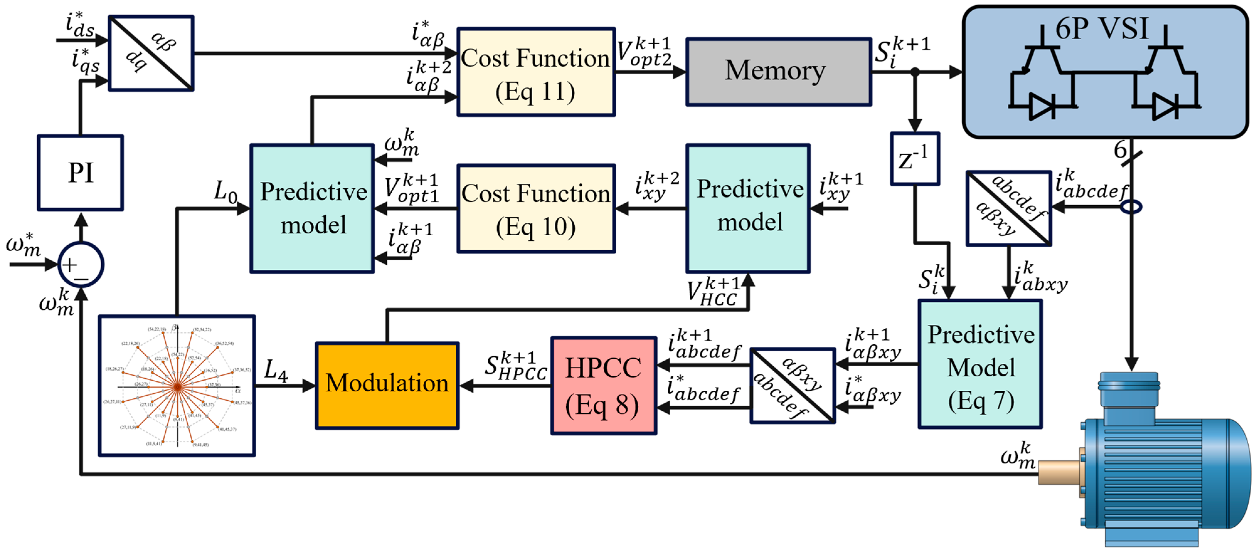
Unfortunately, the solutions presented so far, although promising, still show significant drawbacks, such as high computational cost, high complexity, and the dependency on the weighting factor. Accordingly, in this paper, these three issues are addressed together, providing reduced computational cost and enhanced control performance. Taking into account the aforementioned issues, a hysteresis model predictive current controller (HMPCC) is proposed. The proposed control scheme combines the robustness and simplicity derived from the hysteresis predictive current controllers (HPCCs) with the superior control performance derived from the MPC. HPCC provides a selection of an initial voltage vector that is processed by a modulation stage. Even though the HPCC itself may not select the best control action per sampling period, it can select a region where the optimal voltage vector can be found. Accordingly, a small group of largest voltage vectors and a null vector are selected, which can then be evaluated in the MPC without requiring a weighting factor, avoiding the tedious tuning work. Subsequently, the optimal voltage vector is selected and applied during the next sampling period. Moreover, to reduce the switching frequency, a memory stage is introduced. To the best of the authors’ knowledge, a less computationally demanding HMPCC, which aims to obtain superior control performance, has not yet been reported in the literature for asymmetrical six-phase induction motors (IMs). The proposed HMPCC reduces the number of voltage vectors, resulting in lower computational time, further enhancing the control’s performance. The performance of the proposed control was evaluated and confirmed by means of experimental results.
2. Asymmetrical Six-Phase Induction Motor Drives
The electric multiphase machine under study is an asymmetrical six-phase induction motor (IM) composed of two sets of three-phase windings spatially shifted by 30°. The neutral points of the two sets were isolated to simplify the control stage and improve the DC-link utilization. A six-phase 2L-VSI supplied the IM, as shown in Figure 1. With this configuration, the 2L-VSI provides available switching states. These switching states can be modeled using the vector , where each component represents the binary value of the behavior of each VSI leg, where if the upper switch of the leg i is on and the lower switch of the same leg is off, and if the opposite occurs.
The stator phase voltages can be obtained as a function of the DC-link voltage and the aforementioned vector [S] using the following expression:
Several reference frames and transformations have been widely used in the literature [21]; however, for control purposes, it is a common practice to represent the machine equations using the vector space decomposition (VSD) approach, where phase variables are referenced to a stationary reference frame composed of three sets of orthogonal subspaces. The α-β subspace is related to the flux/torque production, whereas the x-y subspace produces stator copper losses. On the other hand, the z1−z2 subspace is neglected because of the isolated neutral points in the design of the asymmetrical six-phase IM. Using the amplitude-invariant Clarke transformation, it is possible to map the phase voltages into VSD variables as follows (2):
Applying (2) for each switching state of the IM, it is possible to map the 64 possible control actions onto the α-β and x-y subspaces as shown in Figure 2. Each voltage vector is defined by the decimal number corresponding to the binary number of the switching state. Regarding the amplitude of the voltage vectors, they can be sorted in five groups: null , small , medium , medium–large , and large . It can be noted that the voltage vectors from group have the largest amplitude in the α-β subspace but the smallest amplitude in the x-y subspace. In contrast, vectors of group have the smallest amplitude in the α-β subspace but the largest amplitude in the x-y subspace.
Using standard assumptions [15], the model of this multiphase machine can be represented in the state-space representation by employing (3):
where represent the stator voltages, and are the currents from the stator and rotor, respectively. are the resistances of the stator and rotor, respectively, are the phase leakage inductances of the stator and rotor, respectively, is the mutual inductance between them, and is the rotor’s electrical angular speed. The mechanical equations of the asymmetrical six-phase IM are specified as (4)–(6):
where , , , , , and correspond to the inertia coefficient, friction coefficient, rotor mechanical speed, generated electromagnetic torque, load torque, and number of pole pairs, respectively.
3. Proposed HMPCC
3.1. HPCC Principle
The hysteresis current control (HCC) method has been commonly used in many power electronics applications, due to its simple implementation, fast dynamic response, and intrinsic robustness to parameter variations [22]. Moreover, the HCC technique is based on its applicability on nonlinear control techniques, low software requirements, high reliability, and fewer tracking errors [23]. The standard HCC operation is performed by comparing the actual phase current with the corresponding reference in a determined tolerance band, generating the switching states. However, due to several delays in the implementation stage, using the actual phases in the HCC can reduce the performance of the asymmetrical six-phase IM. Therefore, this paper proposes the HPCC, which is similar to the HCC; however, it uses a mathematical model to predict the phase currents. Based on the previous model Equation (3), by using the Euler method, the phase currents in the α-β axis, in their discrete form, can be predicted as follows [15]:
Then, using the inverse Clarke transformation (2), the predicted phases can be obtained. The HPCC algorithm in the six-phase IM uses six hysteresis comparators to generate the inverter input signals, as shown in Figure 3. Comparators use the error between the predicted phase current and the corresponding reference for each phase in order to ensure that the values are maintained within a defined hysteresis band, , so that if the error exceeds the upper limit of the band, the upper semiconductor is turned on and the lower semiconductor is turned off. On the other hand, if the error exceeds the lower limit of the band, the upper semiconductor is turned off and the lower one is turned on, ensuring that the current remains within the limits of the hysteresis band [24].
The hysteresis bandwidth value is fixed for better control performance. Therefore, a hysteresis bandwidth sets the standard for HPCC performance. HPCC works by directly controlling the motor phase currents. The following expression (8) summarizes the operational principle of HPCC:
where denotes the switching state of the upper semiconductor in the inverter arm of each phase, while the lower semiconductor takes the complementary state; and are the reference and predicted phase currents, respectively, where the subscript “” represents the phase. Regarding the speed regulation, this task is carried out using a PI controller. The output of the speed controller generates the reference value of the q-current (), whereas the reference value of the d-current is assumed to be constant and proportional to the rated magnetic flux.
3.2. Modulation Stage
Even though the HPCC is the improved version of the standard HCC, it has some limitations, especially in controlling the asymmetrical six-phase IM, since the HPCC can employ all of the possible switching states shown in Figure 2. Employing all of the possible switching states in an asymmetrical six-phase IM will result in higher switching losses and less efficiency due to the use of all magnitudes of voltage vectors, which is not suitable for high-power applications. Additionally, it is hard to integrate control constraints as in MPC. Under normal operation, the HPCC may not select the optimal voltage vector. However, it can select a region where the optimal voltage vector can be found. Therefore, the modulation stage is introduced in this method to select a small group of the feasible voltage vectors within that region. Accordingly, this paper proposes the combination of the HPCC with the MPC, allowing the number of iterations evaluated in the MPC to be reduced, resulting in a lower computational burden, reduced switching losses of the VSI, and obviation of the weighting factor design, thereby enhancing the drive’s performance.
In this modulation step, based on Equation (8), a voltage vector is obtained from the HPCC; this voltage vector will determine a region. Then, a combination of the largest voltage vectors from group is chosen for the prediction step. For instance, if the HPCC provides one voltage vector from the three vectors aligned in the α-β subspace (see Figure 4), this modulation stage chooses the selected largest voltage vector and the two largest voltage vectors nearby. Another case may exist: if the HPCC provides one medium voltage vector (), the modulation step chooses the two closest large voltage vectors (see Figure 4). Moreover, if the HPCC provides a null voltage vector, in this last case, the null voltage vector is chosen as the optimal voltage vector, and no large voltage vectors are chosen. Additionally, in each case, a null voltage vector is also added to improve the drive’s performance. Selecting only the large voltage vectors in the modulation stage leads to the mitigation of the current harmonic distortion, corresponding to reduced system losses and better power quality.
3.3. Predictive Current Control
Numerous schemes have been recently proposed for the high-performance regulation of electric drives. One of the recent and most promising controls is MPC, due to the ease of including restrictions in its cost function and its good dynamic response. MPC uses a forward Euler discretization technique to obtain the predictive model, which estimates the future states of the drive and then selects the most suitable control action for application in the next sampling period, by minimizing a cost function where the error between the predicted system outputs and their reference values is evaluated. For good control performance, the predictive model relies on the knowledge of some variables, e.g., the measured part, which includes the stator currents, rotor speed, and stator voltages; and the unmeasurable part, which refers to the rotor variables. Thus, to minimize the computational effort as much as possible, the method C1a from [25] is used in this paper, where the rotor currents () are lumped into one term—designated G—and they are estimated at every sampling period using past values of the measured variables. In standard MPC for an asymmetrical six-phase IM, 49 iterations are performed, resulting in a high computational effort, requiring higher-performance digital processors, which are expensive. Therefore, cost function (9) is used in the standard MPC, where all the voltage vectors are evaluated and the weighting factor has to be well estimated to achieve superior control performance:
where [, ] are set to zero. The constant K represents the weighting factor, and its value must be selected according to the control objectives.
On the other hand, the proposed method takes advantage of the use of the hybrid control solution; thus, the weighting factor can be eliminated in a simple way. Firstly, the largest feasible voltage vectors selected from Figure 4 are introduced in the cost function (10). It should be noted that the cost function (10) does not have α-β components, due to the fact that the HMPCC is a hybrid solution, constituted by two different controls, so the largest feasible voltage vectors are naturally voltage vectors that will produce torque/flux and, thus, there is no need to introduce them in the cost function, thereby simplifying the cost function and the computational effort.
Additionally, to improve the torque quality, a null voltage vector must be also evaluated, albeit in a secondary cost function (11). This cost function is exclusively for improving the torque quality; therefore, the previous voltage vector selected in (19) is now evaluated in (11) together with the null voltage vector. It should be noted that the null voltage vector cannot be evaluated in the previous cost function (10), since it does not produce x-y voltage or torque/flux.
The voltage vector with the smallest error in is chosen as the optimal voltage vector and applied to the six-phase inverter during the next sampling time. The proposed method evaluates three or four different voltage vectors per sampling period, without requiring tuning of the weighting factor, due to the hybrid solution, resulting in a significant reduction in the iteration steps and computation effort.
3.4. Memory Stage
Even though the HPCC provides more precision and, therefore, better regulation of the asymmetrical six-phase IM than the HCC, its switching frequency (fsw) is higher. Thus, to address the reduction in VSI switching losses, it is appropriate to select the optimal null voltage vector through a memory step. The memory step saves the last voltage vector employed to the 2L-VSI and, if a null voltage vector is selected as the optimal voltage vector, it compares the previous switching states of that previous voltage vector with the four different null voltage states. Then, the memory step selects the best null voltage vector among the four, reducing the VSI switching losses. For example, if V18 was employed, and Equation (10) chooses a null voltage vector as the optimal (Figure 5), the null voltage vector that suffers the fewest switching changes is V0, employing only two switching changes.
The same principle also applies to any other similar situation that might occur. This optimization is performed offline, so it does not add computational effort to the control.
In Figure 6, a simplified scheme of the proposed method is presented.
4. Experimental Validation
4.1. Experimental Test Bench
The performance of the proposed HMPCC was experimentally validated. The test bench used for the experiments is shown in Figure 7. It comprises an asymmetrical six-phase IM connected to a two-level dual three-phase VSI (Powerex POW-RPAK modules), using a single DC voltage source. The VSI is controlled in real time by a dSPACE DS1103 digital signal processor, with MATLAB/Simulink incorporated. The dSPACE reads and acquires data related to torque, rotation speed, and electrical quantities. The asymmetrical six-phase IM is loaded by coupling the shaft to an AC machine that acts as a generator. The AC machine is connected to a variable passive R load that dissipates the power, and the load torque is consequently speed-dependent. The parameters of the asymmetrical six-phase IM are listed in Table 1.
4.2. Experimental Results
Initially, the performance of the methods described throughout this paper was compared, namely, HCC, HPCC, MPC with all possible control actions (hereafter referred to as MPC49), MPC with the largest voltage vectors and the null vector (hereafter referred to as MPC13), and the proposed control HMPCC. The control methods were compared in a single test, where four control performance variables were analyzed: the total harmonic distortion (THD), the switching frequency (), the average execution time (), and the standard deviation of the x-y currents (). The THD of the six phases can be calculated as follows:
On the other hand, the standard deviation of the x-y currents is expressed as follows:
where is the current sample value, is the mean current value, and is the total number of samples.
Experimental tests were conducted in order to validate the proposed algorithm, its feasibility, and its control performance. To conduct a fair comparison, the sampling frequency was set to 20 kHz.
A first test (see Figure 8) was used to verify the steady-state performance with a constant reference speed of 1000 r/min and an imposed load torque of 7.4 Nm. In this test, the authors compared the performance of the aforementioned controls. An initial comparison showed that the HPCC and HCC have very low execution times due to their simplicity (see Table A1 in Appendix A); however, HPCC shows a big improvement in regulating the asymmetrical six-phase IM, presenting less harmonic distortion (Figure 8a,b), due to the use of the predictive mathematical model. Moreover, it can be seen that the THD decreases from 23.5% to 13.2% (see Table A1 in Appendix A). However, the HPCC has twice the switching frequency. On the other hand, under the same conditions, MPC49 (Figure 8c) has optimized α-β reference tracking and can strictly regulate the x-y currents, which are related to the drive’s performance, due to its predictive nature, selecting the best control action from a finite set of actions. MPC49 has a similar switching frequency to HPCC, due to the use of all magnitudes of voltage vectors from Figure 2, which implies more switching changes. Moreover, as expected, MPC49 has a higher computational burden. Conversely, MPC13 (Figure 8d) can reduce the computational effort from 36.7 µs to 24.5 µs (see Table A1 in Appendix A), since it evaluates 32 fewer control actions per sampling period; it can also reduce the switching frequency, because switching states from a large voltage vector to another large voltage vector involves fewer switches [26] and fewer parasitic currents (x-y) [15], since the large voltage vector in the α-β subspace represents the smallest vector in the x-y subspace. In Figure 8e, the performance of the proposed hybrid method is presented. It can be verified that the x-y components show a significant decrement compared to the previous controls, since this method uses a different cost function that does not resort to the weighting factor, unlike MPC13 or MPC49, thereby avoiding the complex tuning process. Furthermore, this pertinent decrease in the x-y components leads to enhanced efficiency in the machine without the requirement of sophisticated modulation schemes or additional controllers. Even though the proposed method is a combination of two distinct controls, the computational burden is similar to that of MPC13, achieving a reduction of 34% in the execution time when compared to MPC49. Moreover, the switching frequency is quite similar to that of MPC13. It is also worth mentioning that, if the HMPCC uses the standard cost function (Equation (9)), a similar performance to that of MPC13 is expected. Hereafter, only MPC49, MPC13, and the proposed HMPCC are compared, since they exhibit the most similar behavior and present the best performance.
A second test (see Figure 9) showed the THD, switching frequency values (), and the standard deviation of the x-y currents () for a steady-state performance under different speeds with active load and without load. In almost every case, the proposed method showed less THD (see Figure 9a) and switching frequency (see Figure 9b), with some exceptions (see Table A2 in Appendix A). This is because the proposed technique has zero dependency on the weighting factor, so it can provide better values of THD in the overall test; additionally, the memory stage takes advantage of the four different null vectors and, therefore, employs the best null voltage vector that provides fewer switching changes, which is more noticeable at lower speeds (see Table A2 in Appendix A). It can also be noted, for higher speed with active loads, that the proposed method has an increased switching frequency, but still similar to that of MPC49. This increase in the switching frequency is quite acceptable, since the HMPCC shows the best regulation of the x-y components for the different scenarios (see Figure 9c).
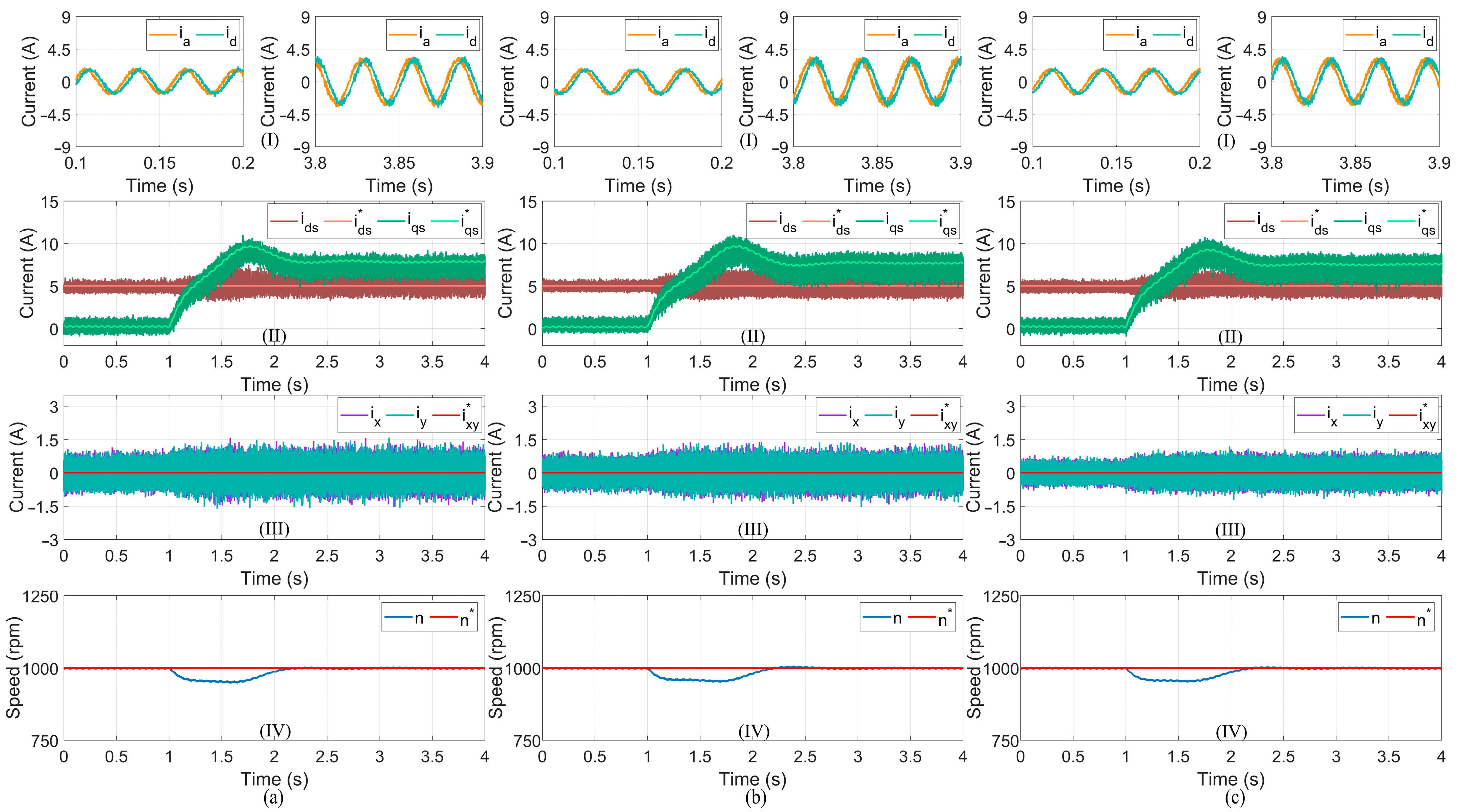
A third test (see Figure 10) verified the transient-state response of MPC49, MPC13, and the proposed method. The motor speed was set to 1000 r/min, with a transition load torque of 1.5 Nm at t = 1 s to 7.4 Nm. MPC49, MPC13, and HMPCC showed great dynamic responses and high accuracy in tracking the rotor speed. It was observed that the MPC49 tracked the d-q reference currents better, due to the use of all control actions. However, as before, the x-y currents were better regulated with the proposed method. This can be explained because the HMPCC uses a different cost function that does not evaluate the α-β subspace—only the x-y subspace (Equation (10)). This cost function cannot be used in standard MPC methods because it would choose a voltage vector that does not produce torque/flux and does not produce x-y currents, resulting in no motion being produced. This technique can only be employed in hybrid controls (i.e., composed of two different controls) that complement one another in different ways. Since HPCC is not good enough by itself, if combined with an MPC scheme, the overall performance can be improved, resulting in a totally different control. Thus, using a cost function that only controls the x-y components will better regulate the x-y currents, enhancing the efficiency of the machine.
A summary of the performance indicators for the different control strategies in Test 3 is presented in Table A3 in Appendix A. As with the previous results, the IM currents are better regulated with the proposed method, presenting a lower THD and (see Table A3 in Appendix A). The is lower in the proposed method due to the inclusion of the memory stage. Additionally, the computational effort is also smaller with the proposed method, even though the proposed method is composed of two different methods.
The fourth test (see Figure 11) verified the steady-state performance with a rated speed of 1500 r/min under high torque. We observed an evident deviation of the d-q currents from their reference values, since the MPC methods rely on precise parameters. This offset is more noticeable under a high load torque [27]. Under a high-stress scenario, both MPC49 (see Figure 11a) and MPC13 (see Figure 11b) show a similar performance in both the d-q and x-y components, with a similar THD, switching frequency, and standard deviation of the x-y currents (see Table A4 in Appendix A), since in this scenario the most commonly used voltage vectors are the largest voltage vectors. Additionally, it can be seen that the proposed method presents more ripple in the d-q currents. Indeed, such a slight increase in the d-q currents is quite acceptable considering the significant contribution offered by the proposed HMPCC. It can be also observed that the proposed HMPCC has similar values of THD and switching frequency (see Table A4 in Appendix A). However, the x-y components are better regulated (see Figure 11c) for the aforementioned reasons, enhancing the efficiency of the drive.
To further show the advantages of HMPCC, Table 2 establishes a comparison between FOC, DTC, MPC49, and HMPCC. It can be seen that, for the tuning parameters, DTC requires four tuning parameters, of which two are for the PI controllers and the other two are for the hysteresis controllers. FOC has five PI controllers, with which 10 parameters are calculated and tuned. On the other hand, MPC49 needs two parameters for the PI controller and one for the weighting factor in the cost function. The HMPCC requires three parameters: one for the six hysteresis controllers and two for the PI controllers. As for the internal controllers, DTC uses two hysteresis controllers, FOC uses four PI controllers, MPC49 uses a cost function to evaluate the stator current errors, and HMPCC uses six hysteresis controllers for each machine phase and two cost functions that can avoid the weighting factor parameter tuning. FOC requires a modulator to generate the switching states and, thus, has a fixed switching frequency, whereas the other three methods directly generate the switching states in their controls, not requiring a modulator. One of the major advantages of MPC49 relative to DTC and FOC is the ability to easily integrate multiple constraints into the cost function, as for DTC and FOC it is complicated to add constraints. In MPC methods (e.g., MPC49 and HMPCC), it is common to include the x-y currents [15] in the cost function, since in this way the harmonic distortion is well regulated, improving the overall system’s performance. In classic DTC, the main goal is to control the torque, disregarding the harmonic distortion, while in FOC the harmonic distortion is better regulated than in DTC, since it uses a modulator. However, it has much inferior performance in regulating the harmonic distortion when compared with MPC methods. Another significant feature of MPC methods (e.g., MPC49 and HMPCC) is the ability to predict the future optimal behavior of the six-phase IM, where in every control action the reference is compared with the predicted values, and the control action that presents the smallest error is employed, thereby presenting an excellent control dynamic. On the other hand, FOC presents a fast system dynamic since it directly controls the torque. As far as FOC is concerned, its dynamic is limited due to the use of a modulator that employs a null voltage vector in a transient state, thereby requiring a longer settling time [11]. As presented in Table 2, MPC49 presents a high computational burden, due to the fact that it evaluates 49 different switching states for each sampling time period. On the other hand, the HMPCC has the advantages of the classic MPC49, with the added advantage of a low computational cost, similar to that of DTC and FOC, without requiring weighting factor tuning in the cost function.
In summary, the proposed HMPCC overcomes the limitations of MPC49 and MPC13 in terms of better regulating the x-y components under all conditions. This enhanced performance is obtained without demanding a weight factor parameter. Additionally, this solution can be used with multiple voltage vector solutions to improve the current quality.
5. Conclusions
This paper proposes a low-complexity HMPCC where two distinct controls are combined (HPCC and MPC), which can greatly reduce the computational burden, decrease the current harmonics, and avoid the use of a weighting factor. Firstly, the HPCC provides a voltage vector and, accordingly, it selects the most appropriated large voltage vector from the α-β subspace. Subsequently, the MPC evaluates the feasible voltage vectors without requiring a weighting factor. The voltage vectors are reduced from 49 to 3 or 4 from the conventional MPC to the proposed algorithm, representing a reduction of approximately 34% in the execution time required. Consequently, the predictive control is less computationally demanding and does not require the tuning of the weighting factor, making it an attractive and cost-effective solution. Based on the experimental results, it can be concluded that the proposed method is effective in reducing the x-y currents without compromising the α-β components, providing enhanced control performance of the asymmetrical six-phase IM under the same conditions.
Author Contributions
Conceptualization, J.S. and A.J.M.C.; methodology, J.S. and A.J.M.C.; software, J.S.; validation J.S.; formal analysis, J.S. and A.J.M.C.; investigation, J.S. and A.J.M.C.; resources, A.J.M.C.; data curation, J.S.; writing—original draft preparation, J.S.; writing—review and editing, A.J.M.C.; visualization, J.S. and A.J.M.C.; supervision, A.J.M.C.; project administration, A.J.M.C.; funding acquisition, A.J.M.C. All authors have read and agreed to the published version of the manuscript.
Funding
This work was supported by the Portuguese Foundation for Science and Technology (FCT) under Projects UIDB/04131/2020, UIDP/04131/2020, and 2022.14121.BD.
Data Availability Statement
Not applicable.
Conflicts of Interest
The authors declare no conflict of interest.
Appendix A
Summary of performance indicators (i.e., the total harmonic distortion (THD), the switching frequency (), the average execution time (), and the standard deviation of the x-y currents ()) for the control strategies (i.e., MPC49, MPC13, and HMPCC) applied to the asymmetrical six-phase IM in the different tests.

Table A1.
Summary of the performance indicators for the control strategies applied to the asymmetrical six-phase IM (Test 1).
Table A1.
Summary of the performance indicators for the control strategies applied to the asymmetrical six-phase IM (Test 1).
| Controls | Speed (r/min) | Torque (Nm) | THD (%) | fsw (kHz) | σxy (A) | texe (µs) |
|---|---|---|---|---|---|---|
| HCC | 1000 | 7.4 | 23.5 | 2.3 | 1.374 | 19.72 |
| HPCC | 1000 | 7.4 | 13.2 | 4.2 | 0.600 | 21.48 |
| MPC49 | 1000 | 7.4 | 12.3 | 4.1 | 0.445 | 36.67 |
| MPC13 | 1000 | 7.4 | 13.2 | 3.3 | 0.400 | 24.47 |
| HMPCC | 1000 | 7.4 | 12.0 | 3.5 | 0.339 | 24.16 |
Table A2.
Summary of the performance indicators for the control strategies applied to the asymmetrical six-phase IM (Test 2).
Table A2.
Summary of the performance indicators for the control strategies applied to the asymmetrical six-phase IM (Test 2).
| Controls | Speed (r/min) | Torque (Nm) | THD (%) | fsw (kHz) | σxy (A) | texe (µs) |
|---|---|---|---|---|---|---|
| MPC49 | 300 | 1.5 | 7.4 | 6.1 | 0.167 | 36.67 |
| 600 | 1.5 | 8.6 | 4.2 | 0.203 | 36.65 | |
| 900 | 1.5 | 10.5 | 2.8 | 0.241 | 36.67 | |
| 1200 | 1.5 | 12.3 | 2.2 | 0.311 | 36.66 | |
| 1500 | 1.5 | 15.0 | 2.1 | 0.387 | 36.65 | |
| 300 | 3.4 | 8.6 | 6.1 | 0.195 | 36.67 | |
| 600 | 4.9 | 9.0 | 5.0 | 0.256 | 36.66 | |
| 900 | 6.7 | 8.9 | 3.8 | 0.319 | 36.67 | |
| 1200 | 8.6 | 8.6 | 3.1 | 0.387 | 36.66 | |
| 1500 | 10.6 | 8.3 | 2.5 | 0.454 | 36.66 | |
| MPC13 | 300 | 1.5 | 6.8 | 6.1 | 0.150 | 24.44 |
| 600 | 1.5 | 7.4 | 3.9 | 0.174 | 24.44 | |
| 900 | 1.5 | 8.6 | 2.6 | 0.215 | 24.45 | |
| 1200 | 1.5 | 11.5 | 2.1 | 0.312 | 24.43 | |
| 1500 | 1.5 | 14.5 | 2.0 | 0.379 | 24.42 | |
| 300 | 3.4 | 9.1 | 4.6 | 0.161 | 24.46 | |
| 600 | 4.9 | 9.4 | 3.5 | 0.221 | 24.45 | |
| 900 | 6.7 | 9.0 | 3.0 | 0.290 | 24.45 | |
| 1200 | 8.6 | 8.6 | 2.6 | 0.355 | 24.45 | |
| 1500 | 10.6 | 8.3 | 2.2 | 0.427 | 24.44 | |
| HMPCC | 300 | 1.5 | 6.8 | 4.5 | 0.119 | 24.18 |
| 600 | 1.5 | 7.4 | 3.5 | 0.146 | 24.10 | |
| 900 | 1.5 | 8.8 | 2.6 | 0.172 | 24.06 | |
| 1200 | 1.5 | 10.5 | 2.2 | 0.204 | 24.01 | |
| 1500 | 1.5 | 12.5 | 2.1 | 0.238 | 24.01 | |
| 300 | 3.4 | 8.7 | 4.1 | 0.137 | 24.15 | |
| 600 | 4.9 | 9.0 | 3.4 | 0.193 | 24.11 | |
| 900 | 6.7 | 8.7 | 3.0 | 0.244 | 24.10 | |
| 1200 | 8.6 | 8.4 | 2.7 | 0.290 | 24.07 | |
| 1500 | 10.6 | 8.0 | 2.4 | 0.330 | 24.05 |
Table A3.
Summary of the performance indicators for the control strategies applied to the asymmetrical six-phase IM (Test 3).
Table A3.
Summary of the performance indicators for the control strategies applied to the asymmetrical six-phase IM (Test 3).
| Controls | Speed (r/min) | Torque (Nm) | THD (%) | fsw (kHz) | σxy (A) | texe (µs) |
|---|---|---|---|---|---|---|
| MPC49 | 1000 | 1.5 | 14.3 | 2.8 | 0.274 | 36.64 |
| 1000 | 7.4 | 11.3 | 4.0 | 0.442 | ||
| MPC13 | 1000 | 1.5 | 12.7 | 2.5 | 0.254 | 24.45 |
| 1000 | 7.4 | 12.4 | 3.4 | 0.388 | ||
| HMPCC | 1000 | 1.5 | 12.4 | 2.3 | 0.184 | 24.09 |
| 1000 | 7.4 | 11.4 | 3.3 | 0.306 |
Table A4.
Summary of the performance indicators for the control strategies applied to the asymmetrical six-phase IM (Test 4).
Table A4.
Summary of the performance indicators for the control strategies applied to the asymmetrical six-phase IM (Test 4).
| Controls | Speed (r/min) | Torque (Nm) | THD (%) | fsw (kHz) | σxy (A) | texe (µs) |
|---|---|---|---|---|---|---|
| MPC49 | 1500 | 18.0 | 5.1 | 1.7 | 0.536 | 36.68 |
| MPC13 | 1500 | 18.0 | 4.9 | 1.6 | 0.503 | 24.45 |
| HMPCC | 1500 | 18.0 | 5.1 | 1.8 | 0.351 | 24.01 |
References
- Levi, E.; Barrero, F.; Duran, M.J. Multiphase Machines and Drives—Revisited. IEEE Trans. Ind. Electron. 2016, 63, 429–432. [Google Scholar] [CrossRef] [Green Version]
- Levi, E. Advances in Converter Control and Innovative Exploitation of Additional Degrees of Freedom for Multiphase Machines. IEEE Trans. Ind. Electron. 2016, 63, 433–448. [Google Scholar] [CrossRef] [Green Version]
- Serra, J.; Jlassi, I.; Cardoso, A.J.M. A Computationally Efficient Model Predictive Control of Six-Phase Induction Machines Based on Deadbeat Control. Machines 2021, 9, 306. [Google Scholar] [CrossRef]
- Luo, Y.; Liu, C. Multi-Vector-Based Model Predictive Torque Control for a Six-Phase PMSM Motor with Fixed Switching Frequency. IEEE Trans. Energy Convers. 2019, 34, 1369–1379. [Google Scholar] [CrossRef]
- Aciego, J.J.; González Prieto, I.; Duran, M.J.; Bermudez, M.; Salas-Biedma, P. Model Predictive Control Based on Dynamic Voltage Vectors for Six-Phase Induction Machines. IEEE J. Emerg. Sel. Top. Power Electron. 2021, 9, 2710–2722. [Google Scholar] [CrossRef]
- Gonzalez-Prieto, A.; Martin, C.; González-Prieto, I.; Duran, M.J.; Carrillo-Ríos, J.; Aciego, J.J. Hybrid Multivector FCS–MPC for Six-Phase Electric Drives. IEEE Trans. Power Electron. 2022, 37, 8988–8999. [Google Scholar] [CrossRef]
- Che, H.S.; Abdel-Khalik, A.S.; Dordevic, O.; Levi, E. Parameter Estimation of Asymmetrical Six-Phase Induction Machines Using Modified Standard Tests. IEEE Trans. Ind. Electron. 2017, 64, 6075–6085. [Google Scholar] [CrossRef] [Green Version]
- Garcia-Entrambasaguas, P.; González-Prieto, I.; Duran, M.J. Single-Index Open-Phase Fault Detection Method for Six-Phase Electric Drives. IEEE Trans. Ind. Electron. 2020, 67, 10233–10242. [Google Scholar] [CrossRef]
- Duran, M.J.; Levi, E.; Barrero, F. Multiphase Electric Drives: Introduction. In Wiley Encyclopedia of Electrical and Electronics Engineering; John Wiley & Sons, Ltd.: Hoboken, NJ, USA, 2017; pp. 1–26. ISBN 978-0-471-34608-1. [Google Scholar]
- Paredes, J.; Prieto, B.; Satrústegui, M.; Elósegui, I.; González, P. Improving the Performance of a 1-MW Induction Machine by Optimally Shifting from a Three-Phase to a Six-Phase Machine Design by Rearranging the Coil Connections. IEEE Trans. Ind. Electron. 2021, 68, 1035–1045. [Google Scholar] [CrossRef]
- Wang, F.; Zhang, Z.; Mei, X.; Rodríguez, J.; Kennel, R. Advanced Control Strategies of Induction Machine: Field Oriented Control, Direct Torque Control and Model Predictive Control. Energies 2018, 11, 120. [Google Scholar] [CrossRef]
- Jlassi, I.; Marques Cardoso, A.J. Model Predictive Current Control of Synchronous Reluctance Motors, Including Saturation and Iron Losses. In Proceedings of the 2018 XIII International Conference on Electrical Machines (ICEM), Alexandroupoli, Greece, 3–6 September 2018; pp. 1598–1603. [Google Scholar]
- Jlassi, I.; Marques Cardoso, A.J. Lookup-Table-Based Model Predictive Torque Control Without Weighting Factors for PMSM Drives. In Proceedings of the IECON 2019—45th Annual Conference of the IEEE Industrial Electronics Society, Lisbon, Portugal, 14–17 October 2019; Volume 1, pp. 1165–1170. [Google Scholar]
- Vazquez, S.; Rodriguez, J.; Rivera, M.; Franquelo, L.G.; Norambuena, M. Model Predictive Control for Power Converters and Drives: Advances and Trends. IEEE Trans. Ind. Electron. 2017, 64, 935–947. [Google Scholar] [CrossRef] [Green Version]
- Barrero, F.; Arahal, M.R.; Gregor, R.; Toral, S.; Duran, M.J. A Proof of Concept Study of Predictive Current Control for VSI-Driven Asymmetrical Dual Three-Phase AC Machines. IEEE Trans. Ind. Electron. 2009, 56, 1937–1954. [Google Scholar] [CrossRef]
- Luo, Y.; Liu, C. A Simplified Model Predictive Control for a Dual Three-Phase PMSM With Reduced Harmonic Currents. IEEE Trans. Ind. Electron. 2018, 65, 9079–9089. [Google Scholar] [CrossRef]
- Luo, Y.; Liu, C. Elimination of Harmonic Currents Using a Reference Voltage Vector Based-Model Predictive Control for a Six-Phase PMSM Motor. IEEE Trans. Power Electron. 2019, 34, 6960–6972. [Google Scholar] [CrossRef]
- Cortes, P.; Kouro, S.; La Rocca, B.; Vargas, R.; Rodriguez, J.; Leon, J.I.; Vazquez, S.; Franquelo, L.G. Guidelines for Weighting Factors Design in Model Predictive Control of Power Converters and Drives. In Proceedings of the 2009 IEEE International Conference on Industrial Technology, Churchill, VIC, Australia, 10–13 February 2009; pp. 1–7. [Google Scholar]
- Yang, Y.; Pan, J.; Wen, H.; Zhang, X.; Wang, Y.; Perdikakis, W. Model Predictive Control with Autotuning Weighting Factors for Single-Phase Six-Level Hybrid-Clamped Converters. IEEE Trans. Ind. Electron. 2021, 68, 7946–7956. [Google Scholar] [CrossRef]
- Fretes, H.; Rodas, J.; Doval-Gandoy, J.; Gomez, V.; Gomez, N.; Novak, M.; Rodriguez, J.; Dragičević, T. Pareto Optimal Weighting Factor Design of Predictive Current Controller of a Six-Phase Induction Machine Based on Particle Swarm Optimization Algorithm. IEEE J. Emerg. Sel. Top. Power Electron. 2022, 10, 207–219. [Google Scholar] [CrossRef]
- Zhao, Y.; Lipo, T.A. Space Vector PWM Control of Dual Three-Phase Induction Machine Using Vector Space Decomposition. IEEE Trans. Ind. Appl. 1995, 31, 1100–1109. [Google Scholar] [CrossRef]
- Jun, L.; Dazhi, W. Study and Simulation of a Novel Hysteresis Current Control Strategy. In Proceedings of the 2009 Second International Conference on Intelligent Computation Technology and Automation, Changsha, China, 10–11 October 2009; Volume 2, pp. 306–309. [Google Scholar]
- Mishra, T.; Devanshu, A.; Kumar, N.; Kulkarni, A.R. Comparative Analysis of Hysteresis Current Control and SVPWM on Fuzzy Logic Based Vector Controlled Induction Motor Drive. In Proceedings of the 2016 IEEE 1st International Conference on Power Electronics, Intelligent Control and Energy Systems (ICPEICES), Delhi, India, 4–6 July 2016; pp. 1–6. [Google Scholar]
- Palaniappan, R.G.; Vithayathil, J. A Control Strategy for Reference Wave Adaptive Current Generation. IEEE Trans. Ind. Electron. Control. Instrum. 1980, IECI-27, 92–96. [Google Scholar] [CrossRef]
- Martín, C.; Arahal, M.R.; Barrero, F.; Durán, M.J. Five-Phase Induction Motor Rotor Current Observer for Finite Control Set Model Predictive Control of Stator Current. IEEE Trans. Ind. Electron. 2016, 63, 4527–4538. [Google Scholar] [CrossRef]
- Durán, M.J.; Gonzalez-Prieto, I.; Gonzalez-Prieto, A. Large Virtual Voltage Vectors for Direct Controllers in Six-Phase Electric Drives. Int. J. Electr. Power Energy Syst. 2021, 125, 106425. [Google Scholar] [CrossRef]
- Mesai Ahmed, H.; Jlassi, I.; Marques Cardoso, A.J.; Bentaallah, A. Model-Free Predictive Current Control of Synchronous Reluctance Motors Based on a Recurrent Neural Network. IEEE Trans. Ind. Electron. 2022, 69, 10984–10992. [Google Scholar] [CrossRef]
Figure 1.
Asymmetrical six-phase IM fed by a six-phase 2L-VSI.

Figure 2.
Voltage vectors in the α-β ((a) plots) and x-y ((b) plots) subspaces for an asymmetrical six-phase IM.
Figure 2.
Voltage vectors in the α-β ((a) plots) and x-y ((b) plots) subspaces for an asymmetrical six-phase IM.

Figure 3.
Operation of the hysteresis current controller.

Figure 4.
Selection of the voltage vectors in the modulation stage in HMPCC.

Figure 5.
Memory stage: selecting the best null voltage vector.

Figure 6.
Proposed HMPCC scheme for an asymmetrical six-phase IM.

Figure 7.
General view of the experimental setup.

Figure 8.
Test 1: HCC ((a) plots), HPCC ((b) plots), MPC49 ((c) plots), MPC13 ((d) plots), and the proposed HMPCC ((e) plots)). From top to bottom: (I) α and β currents; (II) x and y currents; (III) the a, b, and c phase currents.
Figure 8.
Test 1: HCC ((a) plots), HPCC ((b) plots), MPC49 ((c) plots), MPC13 ((d) plots), and the proposed HMPCC ((e) plots)). From top to bottom: (I) α and β currents; (II) x and y currents; (III) the a, b, and c phase currents.

Figure 9.
Test 2: THD ((a) plots), switching frequency ((b) plots)), and standard deviation of the x-y currents ((c) plots)) for MPC49, MPC13, and the proposed method under no load and with active load.
Figure 9.
Test 2: THD ((a) plots), switching frequency ((b) plots)), and standard deviation of the x-y currents ((c) plots)) for MPC49, MPC13, and the proposed method under no load and with active load.

Figure 10.
Test 3: MPC49 ((a) plots), MPC13 ((b) plots), and the proposed HMPCC ((c) plots)). From top to bottom: (I) a and d phase currents; (II) d and q currents; (III) x and y currents; (IV) motor speed.
Figure 10.
Test 3: MPC49 ((a) plots), MPC13 ((b) plots), and the proposed HMPCC ((c) plots)). From top to bottom: (I) a and d phase currents; (II) d and q currents; (III) x and y currents; (IV) motor speed.

Figure 11.
Test 4: MPC49 ((a) plots), MPC13 ((b) plots), and the proposed HMPCC ((c) plots)). From top to bottom: (I) the a and d phase currents; (II) d and q currents; (III) x and y currents; (IV) motor speed.
Figure 11.
Test 4: MPC49 ((a) plots), MPC13 ((b) plots), and the proposed HMPCC ((c) plots)). From top to bottom: (I) the a and d phase currents; (II) d and q currents; (III) x and y currents; (IV) motor speed.

Table 1.
Asymmetrical six-phase IM parameters.
| Parameters | Values |
|---|---|
| Power () | 7.5 |
| DC-Link Voltage () | 300 |
| Ipeak () | 8.35 |
| 1500 | |
| 1.03 | |
| 0.8208 | |
| 0.199 | |
| 0.0059 | |
| 0.0059 | |
| 0.01 |
Table 2.
Summary of the indicators for the classic control strategies and the proposed method applied to the asymmetrical six-phase IM.
Table 2.
Summary of the indicators for the classic control strategies and the proposed method applied to the asymmetrical six-phase IM.
| DTC | FOC | PCC49 | HMPCC | |
|---|---|---|---|---|
| Tuning Parameters | 4 | 10 | 3 | 3 |
| Internal Controller | 2 Hysteresis | 4 PI | 1 Cost Function | 6 Hysteresis and 1 Cost Function |
| Fixed Switching Frequency | No | Yes | No | No |
| System Constraints Inclusion | Difficult | Difficult | Easy | Easy |
| Harmonic Distortion Regulation | Bad | Medium | Very Good | Very Good |
| System Dynamics | Fast | Slow | Fast | Fast |
| Average Execution Time | 20.4 µs | 18.8 µs | 36.7 µs | 24.2 µs |
Publisher’s Note: MDPI stays neutral with regard to jurisdictional claims in published maps and institutional affiliations. |
© 2022 by the authors. Licensee MDPI, Basel, Switzerland. This article is an open access article distributed under the terms and conditions of the Creative Commons Attribution (CC BY) license (https://creativecommons.org/licenses/by/4.0/).
Share and Cite
MDPI and ACS Style
Serra, J.; Cardoso, A.J.M. A Simplified Model Predictive Control for Asymmetrical Six-Phase Induction Motors That Eliminates the Weighting Factor. Machines 2022, 10, 1189. https://0-doi-org.brum.beds.ac.uk/10.3390/machines10121189
AMA Style
Serra J, Cardoso AJM. A Simplified Model Predictive Control for Asymmetrical Six-Phase Induction Motors That Eliminates the Weighting Factor. Machines. 2022; 10(12):1189. https://0-doi-org.brum.beds.ac.uk/10.3390/machines10121189
Chicago/Turabian StyleSerra, João, and Antonio J. Marques Cardoso. 2022. "A Simplified Model Predictive Control for Asymmetrical Six-Phase Induction Motors That Eliminates the Weighting Factor" Machines 10, no. 12: 1189. https://0-doi-org.brum.beds.ac.uk/10.3390/machines10121189
Note that from the first issue of 2016, this journal uses article numbers instead of page numbers. See further details here.