
Combined Soft Grasping and Crawling Locomotor Robot for Exterior Navigation of Tubular Structures


1
Department of Industrial Engineering, New Mexico State University, Las Cruces, NM 88003, USA
2
Bioinspired and Biomimetic Robotics (Bio2Robotics) Laboratory, New Mexico State University, Las Cruces, NM 88003, USA
3
Department of Mechanical & Aerospace Engineering, New Mexico State University, Las Cruces, NM 88003, USA
*
Author to whom correspondence should be addressed.
Machines 2024, 12(3), 157; https://0-doi-org.brum.beds.ac.uk/10.3390/machines12030157
Submission received: 29 December 2023
/
Revised: 17 February 2024
/
Accepted: 21 February 2024
/
Published: 24 February 2024
(This article belongs to the Special Issue Biorobotic Locomotion and Cybernetic Control)
Abstract
:This paper presents the design, development, and testing of a robot that combines soft-body grasping and crawling locomotion to navigate tubular objects. Inspired by the natural snakes’ climbing locomotion of tubular objects, the soft robot includes proximal and distal modules with radial expansion/contraction for grasping around the objects and a longitudinal contractile–expandable driving module in-between for providing a bi-directional crawling movement along the length of the object. The robot’s grasping modules are made of fabrics, and the crawling module is made of an extensible pneumatic soft actuator (ePSA). Conceptual designs and CAD models of the robot parts, textile-based inflatable structures, and pneumatic driving mechanisms were developed. The mechanical parts were fabricated using advanced and conventional manufacturing techniques. An Arduino-based electro-pneumatic control board was developed for generating cyclic patterns of grasping and locomotion. Different reinforcing patterns and materials characterize the locomotor actuators’ dynamical responses to the varying input pressures. The robot was tested in a laboratory setting to navigate a cable, and the collected data were used to modify the designs and control software and hardware. The capability of the soft robot for navigating cables in vertical, horizontal, and curved path scenarios was successfully demonstrated. Compared to the initial design, the forward speed is improved three-fold.
1. Introduction
Inspection and health monitoring of infrastructure such as overhead power lines, cables and wire rope, poles, pipes, and pipelines in industrial settings, ships, bridges, streetlamps, lighting rod poles, facilities, warehouses, and outdoor facilities is crucial for reducing the chance of catastrophic accidents and high cost of maintenance and operations. Due to the complex, costly, hazardous, and labor-intensive nature of these tasks, robots and autonomous systems have been developed, utilized, and studied to perform them [1,2,3,4]. Over the past 60 years, several robots have been designed and developed to perform these tasks. These robots can be categorized into the following groups: (1) pole/pipe-climbing, (2) cable climbing, and (3) rope-wire climbing. Remote and direct sensing systems can be integrated to enable these robots to measure and detect properties of the structures and search for and find defects for either repair or replacement procedures. Navigating varying-shape structures using autonomous robots has recently emerged, with various applications, e.g., space exploration, urban search-and-rescue, and inspection, maintenance, and repair of infrastructure. Effective operation requires robots to have versatile locomotion that adapts easily to different environments with a low cost of transportation. The mentioned conventional rigid robots are developed for traversing structures with a specific configuration. The areas for improvement that future research might focus on are as follows: (1) Developing robots that can handle more complex structures like curved poles or branching pipes. (2) Creating better obstacle negotiation capabilities. (3) Exploring alternative adhesion and locomotion methods for increased efficiency and versatility. (4) Simplifying operations and enhancing autonomy for wider practical applications. For comprehensive reviews of conventional (rigid) climbing robots, refer to [1,5,6,7,8,9,10].
To achieve higher maneuverability while navigating complex shape structures, the recent advancements in soft robotics enhance the capabilities of robots by incorporating compliant and structurally deformable bodies that generate a higher complex motion compared to their rigid counterparts and adapt to different environments, tasks, while reducing the possibility of damaging the structures [11,12]. In particular, textile-based (fabrics) and pneumatic artificial muscles (i.e., McKibben actuators) are capable of providing a high load-to-weight ratio [4,13,14]. Despite many research efforts in soft robots’ locomotion and grasping, two growing research areas in soft robotics, the combination of locomotion and grasping capabilities in one soft robotic platform has not been sufficiently studied [4,15,16,17,18]. Yet, there is a unique challenge created by combined grasping–locomotion regarding carrying a payload without compromising its motion capabilities or shape morphing to adjust changes in the robot’s center of mass [15].
Soft crawling robots have gained significant attention due to their expected efficient interactions with varying surroundings and their potential to perform a wide range of tasks, including search and rescue, inspecting infrastructure, surveillance, delivering medications, and assisting humans [19]. In particular, these robots can facilitate the navigation of tubular environments such as pipes and cables and prevalent structural shapes in industrial buildings and infrastructure for inspection and monitoring tasks. Several works in the past developed in-pipe robots [20,21] with various locomotion mechanisms such as worm-like [22], walk-type [23], wheel-base [24], screw-type [25], and snake-type [26]. Worm-like robots that create anchoring forces that allow for a peristaltic wave, which creates locomotion through acrylic pipes [20,27], are the most common type. On the other hand, methods of traversing exterior tubular objects have also been considered; a comprehensive review by Chattopadhyay et al. [21] surveys different locomotion methods of pipe-climbing robots. However, most of these systems consist of traditional rigid robots that are bulky, heavy, and high-cost [28,29,30]. The study concluded that by applying a hybrid system, robots can overcome the problem of motion singularity, especially when steering or navigating complex structures. In addition, biologically inspired robots [31] can address the limitations.
Inspired by the vertical tree climbing locomotion of natural snakes as shown in Figure 1a, for example, Python reticulatus climbing with a variant of concertina locomotion [32,33,34], this work demonstrates the capabilities of a pneumatically actuated soft robot with combined locomotion and grasping features as shown in Figure 1b as a new concept for locomotion along exterior tubular structures while inspecting the structure in close proximity. The design and fabrication procedures of the proposed soft robot with simultaneous locomotion and grasping capabilities, a low weight, and a high power-to-weight ratio are presented. Soft actuators associated with grasping (fabric-based inflatable actuator) and locomotion were characterized. The robot was prototyped, and its locomotion was tested successfully in a laboratory setting for vertical and up-and-down curve navigation. Our contribution can be listed as follows: (1) a fully soft robot design is developed with combined grasping and locomotion capabilities, (2) the presented soft robot can adapt its locomotion to a variety of tubular structures with different configurations and topologies, such as curved, vertical, near vertical, and horizontal, right angles and pole, cable, and rope wire, and (3) a lightweight design with safe and reliable working with very high force-to-weight ratio actuators that result in a robot with a low cost of transport (CoT) compared to its rigid conventional counterparts [1].
The organization of this paper is as follows. Section 2 includes the system description, the design consideration of the soft robots, the prototyping process, the control system design, and the testing and demonstration of the robot’s capabilities. Section 2.1 describes the overall system of the soft robot, its components, and the combined grasping and crawling locomotor concept. In Section 2.2, the designing and prototyping of the soft robot are discussed, which includes the theoretical model of the geometry of the soft fabric actuator design in terms of the design parameters presented in Section 2.2.1 and the details of the soft fabric actuators and the elastomer-based fabrication of the expandable locomotor actuators in Section 2.2.2. Moreover, in Section 2.3, the electro-pneumatic-based control of the soft robot, including both hardware and algorithm, is discussed. Section 3 presents the results of the experimental testing on the locomotion of the soft robot navigating two structures’ configurations. Finally, Section 4 discusses the findings of this study, the power consumption calculation and determining the cost of transportation, alternative approaches to improve the robot’s locomotion performance, and the limitations of the system.
2. Materials and Methods
2.1. System Description
This work presents a soft robot designed to move across tubular structures such as cables, pipes, and tubes. The robot is composed of three sections: the proximal section with a soft grasping element called a grabber/holder actuator (G/HA); the middle section with three ePSAs; and the distal section with a second G/HA. Figure 2 demonstrates the robot’s sequences of grabbing and crawling movements along a tubular structure. The robot’s movement involves four repeating steps, starting with air pressure entering the proximal section, then the middle section, and finally the distal section. The robot then releases air pressure from the proximal section and middle section before reintroducing pressure into the proximal section and releasing air pressure from the distal section. This cycle repeats until the robot has traveled the desired distance along the desired structure. Soft robots are susceptible to material failures and ruptures, and therefore this robot is designed to be fully modular and can be easily disassembled. Each ePSA can be separated and replaced from its connecting point on the G/HAs, and each G/HA can be separated into three soft fabric actuators (SFAs). This feature allows the user to replace any damaged component with minimal effort and also aids in attaching the robot to tubular structures. The robot is hollow along its center to allow the tubular structure to pass through it. Since the G/HAs are made up of easy-to-disassemble SFAs, the user only needs to separate the connection between the two SFAs on each end to place the robot over the tubular structure before re-closing the connection on the SFAs. This soft robot is not constructed with standard rigid robot parts, which means its actuators can be resized to fit along any tubular structure by using larger bladders, sleeves, and SFAs. It is scalable for use along any object similar in shape to a cable.
2.2. Design and Prototyping
The design considerations include (1) the minimum grasping force for the textile-based inflatable bladders to carry the overall weight of the robot without slippage while adapting to the varying size of the tubular object (inner diameter), (2) the optimal displacement and the rate of displacement of the elastomeric extensible actuator for achieving a feasible speed of navigation while still staying flexible enough to adapt to varying shapes and the curvature path of tubular structures, and (3) being light-weight, having a low cost of transportation, and having safe interactions with the exterior surface of structures.
2.2.1. Fabric-Based Soft Actuators for the Grasping Action
Due to their high strength-to-weight ratio, high load-carrying capacity, and range of achievable actuation modalities, pneumatically actuated fabric-based or textile-based soft robots and actuators have been increasingly developed for use in several applications, including soft wearable robots [35,36], soft robotic grippers [37,38], linear and angular motor pouches [39], and programmable bending deformation [40]. In this work, thermoplastic polyurethane (TPU)-coated fabric (Seattle Fabrics Inc., Seattle, WA, USA) with a Young’s modulus of 127.81 MPa [37] was utilized to make the inflatable air cells for the proximal and distal G/HA elements of the robot. The material withstands higher pressures and does not exhibit continuous expansion compared to the prevailing rubbery/elastomer-based soft actuators. Thus, it generates a larger force needed for interaction with tubular structures, providing potentially high friction/adhesion forces with varying surfaces of the structure, and grasps firmly to hold the robot in place.
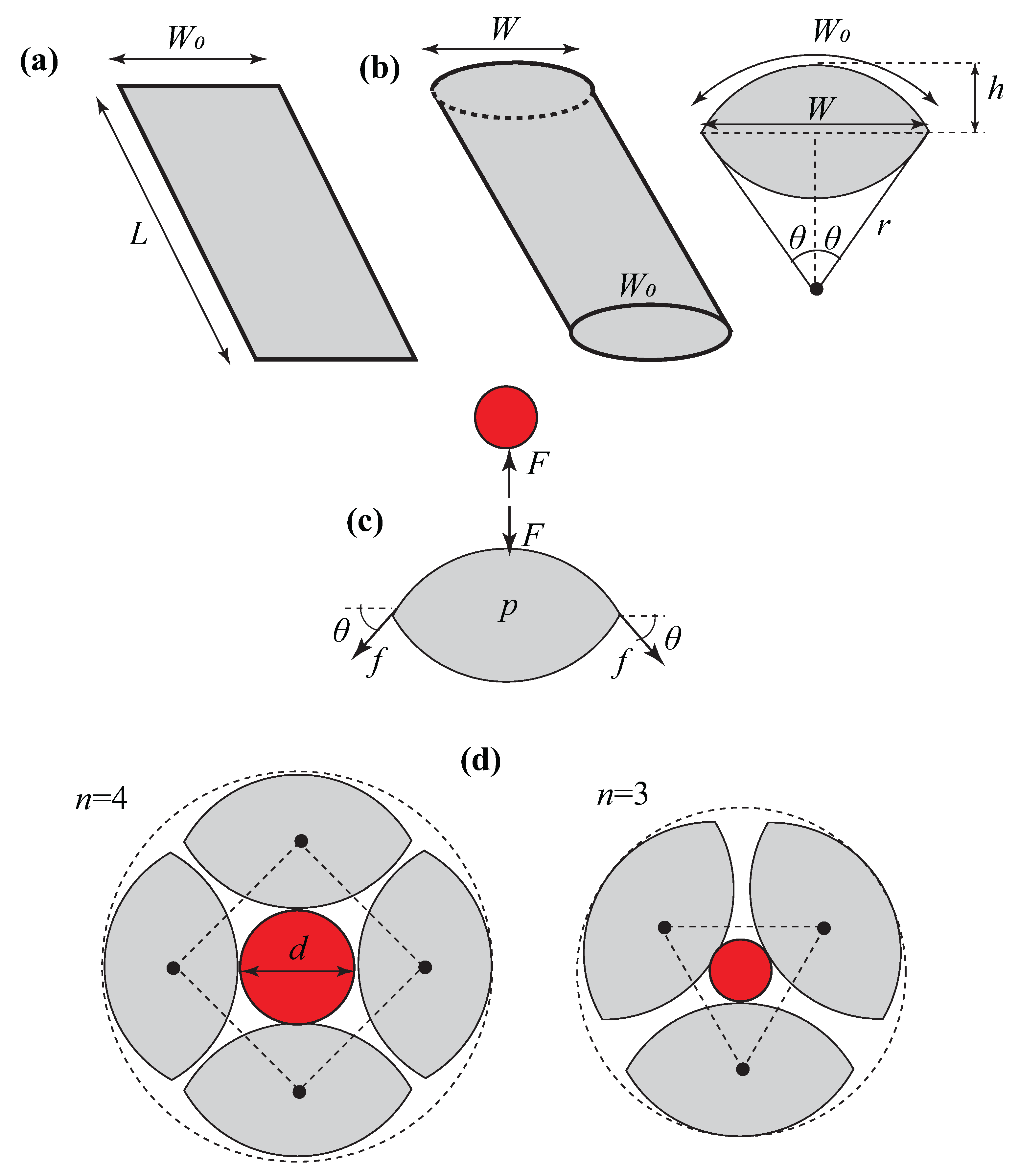
Figure 3a,b show a single SFA air cell before inflation and after inflation, respectively. Each air cell is cut from fabric with a length of L and a width of . After inflation, the length is constant, but the air cell contacts laterally, so it has a current width of W. The geometry of the cross-section of each inflated air cell, as shown in Figure 3b, can be described as follows:
where r, , and h are the radius of the arc, the half angle of the arc, and the distance from the center line of each air cell to the peak of the arc. The volume of the chamber can be obtained by
Figure 3c shows the forces acting on each SFA. We can write the balance of forces acting on each air cell as follows:
where P is the gauge pressure, L is the length of the chamber, and W is the current width of the air cells after inflation. As shown in Figure 3c, F is the external force exerted on each SFA by the tubular structure and f is the tension force, which is given by
where t is the thickness of the fabric or the wall thickness of the air cell chamber, and is the circumferential stress in the fabric and can be calculated based on the virtual cross-section of the area at the end side of the chamber as follows:
h is given by Equation (3). Substituting Equations (7) and (1)–(3) into Equation (5) yields
Considering the air cell as a thin-wall chamber and the material constitutive model of the fabric as an isotropic elastic material (Hook’s law), the axial stress , radial stress , and circumferential strain can be obtained as follows:
where is Poisson’s ratio (≈0.4 for the nylon fabric) and E is Young’s modulus of the fabric, and we assume that there are no stretches in the fabric width, which results in no circumferential strain. Solving for from Equations (9)–(11) gives
By comparing Equations (7) and (12), r and h can be obtained as follows:
Figure 3d shows examples of the G/HA element with three and four air cells conforming around the exterior of a structure; the geometrical configuration dictates that the diameter of the tubular structure is given by
where n is the total number of air cells. On the other hand, the anti-slippery condition during holding/grasping by the air cell requires that
where is the total weight of the soft robot and is the friction coefficient. Equation (16) indicates a constraint on the minimum grip force and actuation pressure.
Based on the theoretical models derived in Section 2.2.1 for the SFA and G/HA, the design parameters include the material, initial dimensions (i.e., length and width), number of air cells, actuation pressure, and range of diameters of the structure that G/HA wraps around.
2.2.2. Prototype
As shown in Figure 4, the soft robot comprises two main components: the extensible pneumatic soft actuator (ePSA) and the G/HA. The G/HA is created by attaching three SFAs with hook and loop fasteners, as shown in Figure 4. Each SFA is made of plastic fabric on one side, allowing a heat sealer to melt two plastic sides together. To create each SFA, first cut out a rectangle of plastic fabric that is 60 mm wide and 200 mm long, with a flap on one side that is 30 mm wide by 160 mm long and lies 20 mm above the base of the larger rectangle. Fold the rectangle in half so that the plastic sides are touching each other, which creates a shape that is mm in length. Next, place the fabric on a sealer and seal each side of the larger rectangle from the inside out, where the air pressure will be held. Seal the side flap, but it does not need to be airtight. Cut a hole in the middle of the top of the larger rectangle, and insert surgical tubing through the hole with at least 20 mm inside the pouch and 30 mm outside. Seal the areas around the tubing with hot glue, and adhere the tube to the SFA.
To make the G/HA, cut 50 mm lengths of hook and loop fasteners and attach the hook side to the extending flap of the SFA. Position the SFA so the flap points to the left before attaching the hooks to the fabric. Flip the SFA over and adhere the loop side to the left side of the SFA (where there is no flap) at the same height as the flap. With the hooks facing upward, use cyanoacrylate glue to adhere a stick to the right side of the SFA. The stick should be 100 mm tall, 7 mm in diameter, and extend 14 mm above the SFA. This is where the ePSAs will attach to the G/HA. Assemble the G/HA by attaching three SFAs with hook and loop fasteners, ensuring that the tube on each SFA points in the same direction. Once two G/HAs are made, place the ends of each PAM on the extended sticks and attach them using a hose clamp. Repeat this procedure for both ends of the PAM to connect both G/HAs. The connector end of each PAM should face in the same direction and be exposed for easy access when connecting them to the air valve.
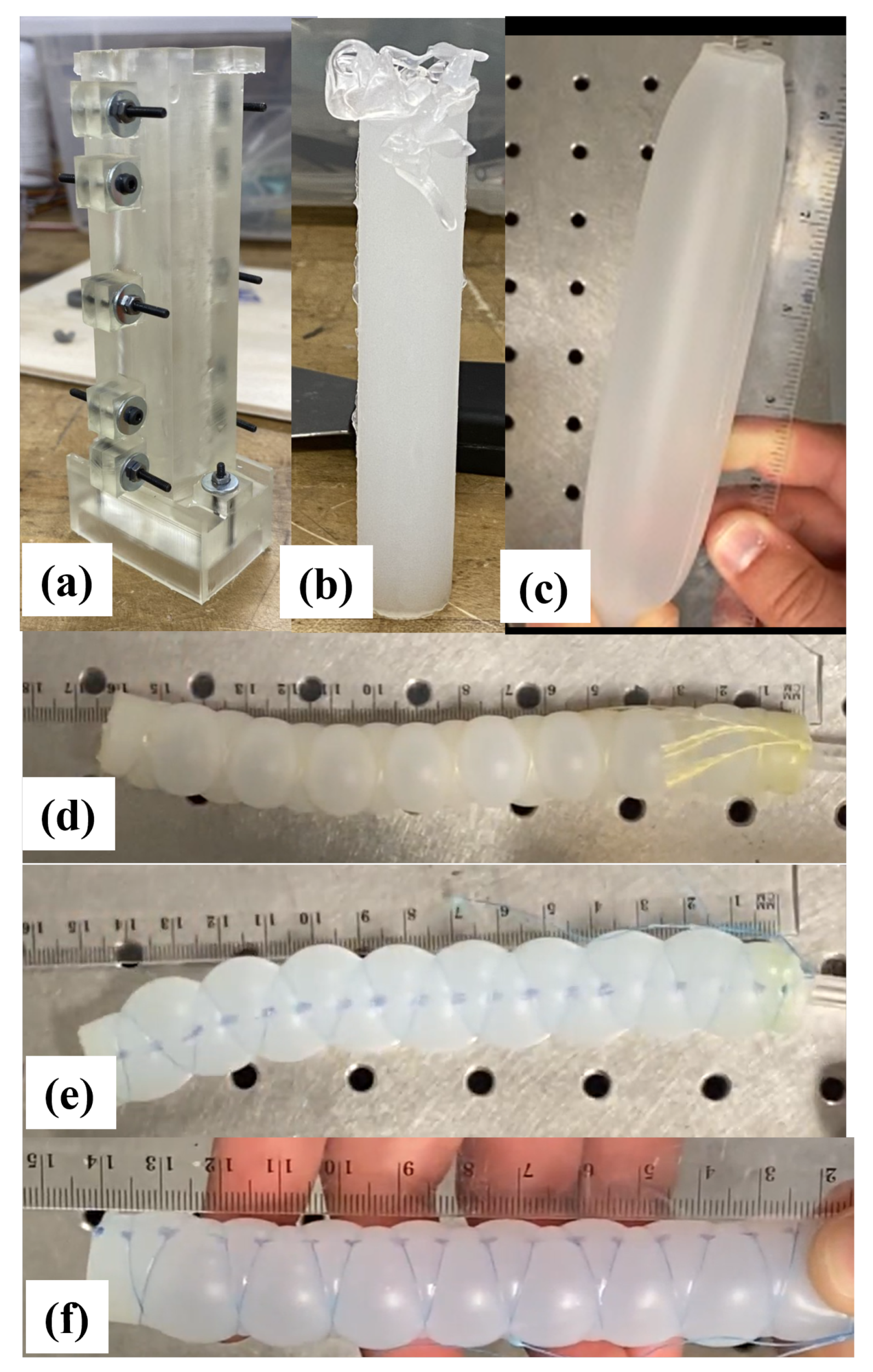
Additionally, extensible pneumatic soft actuators (ePSAs) for integration with the robotic platform were developed and tested, as shown in Figure 5. The key steps included: (1) Mold design and printing: 3D molds for the ePSAs were designed using CAD software, ensuring precise dimensions and tolerances to achieve the desired actuator shapes and performance. The casting molds were printed using an SLA 3D printer (Form 3, Formlabs, Somerville, MA, USA) with clear resin, known for its accuracy and ability to produce high-quality molds for casting elastomers. (2) ePSA casting: EcoFlex 00-50, a soft and flexible silicone material, was chosen for casting the ePSAs due to its suitable elongation and strength properties. ePSAs were cast, incorporating a different type of reinforcing material to explore their effects on performance, including Kevlar line (Figure 5d), Super Slick V2 10 lb weight test fishing line (Figure 5e), and Super Slick V2 20 lb weight test fishing line (Figure 5e). (3) Elongation vs. pressure testing: each ePSA type was tested to measure its elongation (stretch) under varying pressure loads. These data were essential for understanding the actuators’ force–displacement characteristics and suitability for specific applications in the soft robotic system. (4) Adapter design and fabrication: custom adapters, the gray color caps shown in Figure 4, were designed and printed using the Formlabs printer to seamlessly integrate the ePSAs with the soft robot. These adapters ensured proper alignment and attachment of the actuators, enabling effective force transmission and movement control.
2.3. Control System: Hardware and Algorithm
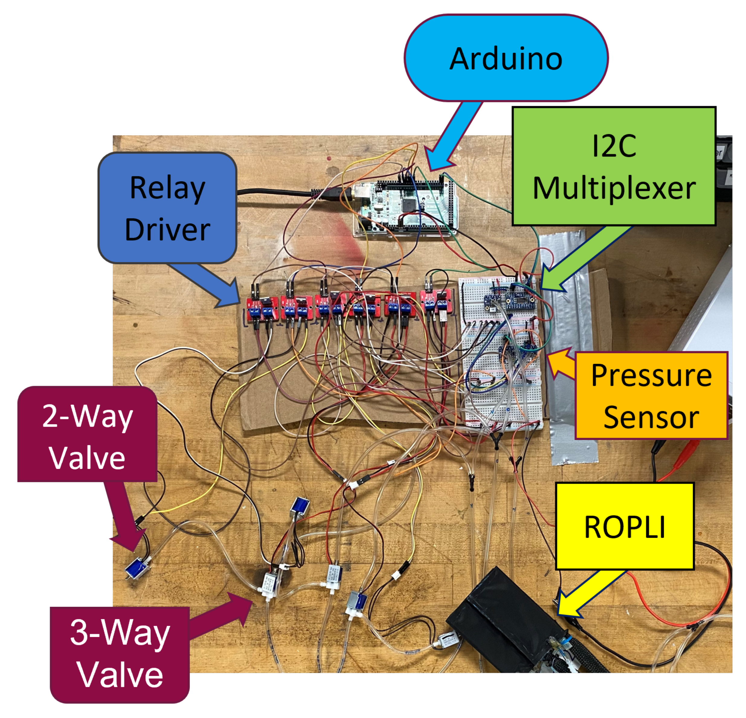
Like many other soft robots, the presented robotic system uses a pneumatic control board to control its movement. The electro-pneumatic control system designed for the robot’s operation is illustrated in Figure 6. The control board regulates pressurized air from the pneumatic airline to each robot section. An Arduino board is used as the microcontroller to control the operation of the electronic and pneumatic components. The prototype of the control board is shown in Figure 5. The pneumatic logic of the controller uses a combination of 2-way and 3-way solenoid valves to inflate individual sections of the soft robot that correspond to the repeating seven steps required for movement, as shown in Figure 2. Each section of the robot has a 2-way valve, a 3-way valve, and a pressure sensor, as illustrated in Figure 6. Pressurized air from the main valve is sent to each 3-way valve, and the air pressure is delivered to a specific section of the soft robot. When that section of the robot is inflated to the necessary air pressure, the 3-way valve will maintain that pressure until the next step in the movement cycle. At this point, the air from the section will be released back through the 3-way valve into the 2-way valve. Here, the 2-way valve will release that air into the atmosphere and then close again, ready for the next time air needs to flow through the 3-way valve into the robot. A schematic of the control diagram with the pneumatic and electronic connections for the two grasping SFA components and three ePSA elements is shown in Figure 7.
2.4. Testing and Demonstration
The soft actuators responsible for the crawling locomotor (i.e., ePSA) were experimentally characterized for three reinforcement materials. The displacement was measured for a range of pressure actuation. In addition, the time response of the solenoid valves in the opening and closing stages was tested. The soft robot, shown in Figure 4, was tested on a horizontal tubular path line to determine the average speed compared to the previous prototype’s performance [4]. Finally, the soft navigation of two different configurations of the tubular structure was demonstrated, including (1) downhill and uphill navigation of a curved path and (2) vertical movement up and down a straight path.
3. Results
The soft robot’s grasping and locomotor elements are characterized. The ePSA-based soft robot’s locomotion was tested in laboratory settings by attaching it to a tubular structure (cable) in two different configurations: (1) traversing a curved path uphill and downhill, and (2) traversing a vertical path up and down. The robot traverses along the cable using the actuation sequences designed in the proposed algorithm. The locomotion was recorded over time, and the results were collected for further analyses, design optimization, and control algorithm modification.
3.1. Soft Actuator Characterization
Initial testing of ePSA variations (Figure 5d–f) indicated that the Kevlar coil form was the preferred actuator for the soft robot’s movement. It created a displacement that was 45% longer than its original length as shown in Figure 8. While the other two variations extended by 50% of their original length, they required 8 and 9 psi to inflate to their optimal length, while the Kevlar coil form only required 7 psi (48.3 kPa). With limitations to the valves that currently control airflow to the soft robot, the 45% increased length at 7 psi (48.3 kPa) was the superior option.
The air cells can theoretically achieve a maximum angle of that leads to , the minimum radius and maximum height of the arc of the chamber, respectively. The required maximum pressure is , which is based on the material properties of the selected fabrics ( MPa) and their thickness ( mm), thus the maximum actuation pressure is 43.8 kPa. However, experimental observations showed that the air cells can only achieve a maximum height of 50% of the theoretical one, i.e., . Also, in order to grasp a larger range of diameter, there is a trade-off between the minimum pressure for the required grip force and greater height. For a friction coefficient of , the current soft robot with three air cells () requires a grip force F of at least 3.27 N. Given the length mm and width mm of each SFA in the G/HA, the required pressure is kPa. The current soft robot can grasp a cable with a maximum diameter of mm. Due to the deformation of the SFA around the cable, the actual diameter can go up to 60 mm for the current design.
3.2. Solenoid Valve Response Time Characterization
The time it takes for a solenoid valve to transition from an open to a closed position or vice versa is known as its response time. It is important to note that the response time differs when energizing or de-energizing a solenoid valve, particularly when using an alternating current. To determine the response time for solenoid valves, the European Fluid Power Committee (C.E.T.O.P.) has established a standard measurement procedure. However, it is worth noting that some valve manufacturers may use different definitions or measurement procedures. When opening the valve, the response time is the duration between energizing the solenoid and reaching 90% of the stabilized outlet pressure. The response time for closing the valve is defined as the duration from de-energizing the solenoid until the pressure drops to 10% of the test pressure. The test is conducted using air at 6 bars at 20 °C.
3.3. Soft Robot Average Speed Comparison
The first generation of our soft robot [4] traversed with an average speed of 0.257 cm/s. With the implementation of ePSA (the Kevlar coil), the soft robot was found to traverse at an average speed of 0.202 cm/s. This outcome shows a reduction in the speed of the soft robot, even though the displacement after a single cycle for the ePSA-based soft robot is 5 cm. In contrast, a displacement of 1.27 cm was achieved for the McKibben pneumatic artificial muscle-based soft robot. Discrepancies in speed were caused by a non-optimal pneumatic control board programming algorithm and the bending in ePSA due to its weight, which is higher than McKibben PAM. To address the former issue, a series of modifications were applied to the control algorithms, including changing the timing and sequences of the inflation and deflation of the combined grasping–crawling locomotor as well as the actuation pressure of ePSA. For the timing, the time to inflate (TTI) and deflate (TTD) was set to 1 s.
Additionally, the following algorithm of sequences was applied: Step (1) Inflate the proximal SFA, deflate the distal, and halfway through the proximal inflation, begin the middle ePSA’s inflation. Step (2) Inflate the distal SFA and deflate the proximal SFA and middle ePSA halfway through the distal inflation. These modifications resulted in a 94.6% increase in the soft robot’s average speed (0.5 cm/s) compared to the McKibben-based soft robot [4]. We also noticed that the proximal G/HA slips back when ePSAs deflate and pull the back segment forward, and the proximal G/HA drags when pulled forward. Increasing the gripping force of the SFA helped to increase the average speed to 0.61 cm/s (a 137.3% increase). Moreover, by increasing the inflation pressure of the ePSA from 8.5 psi to 9.0 psi (56.0 kPa), the average speed reached 0.641 cm/s, 149.4% faster than the McKibben-based soft robot locomotion.
3.4. Downhill and Uphill Navigation of a Curved Tubular Structure
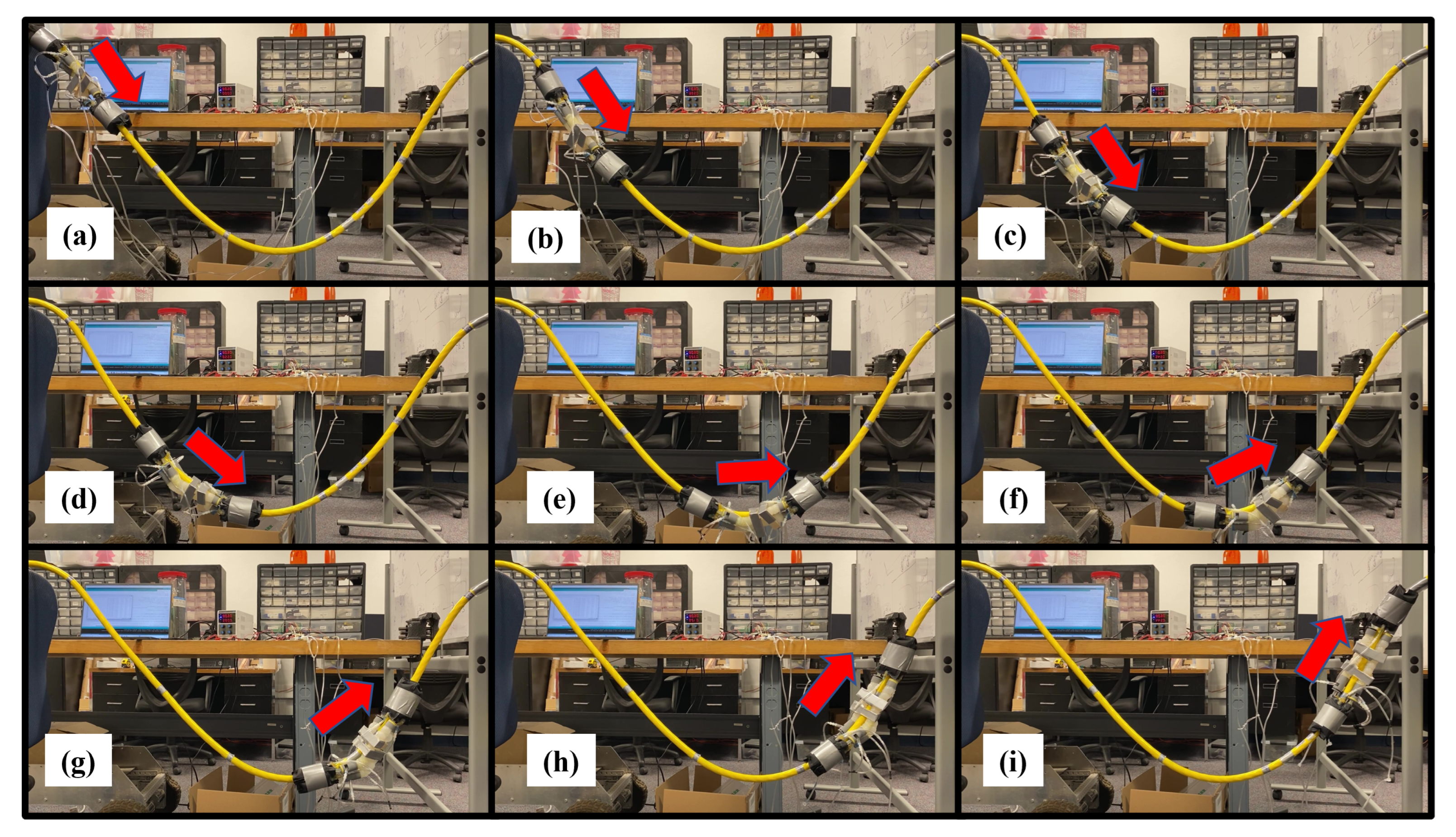
The total distance traveled was 1.59 m in 4.63 min, with an average speed of 5.72 mm/s, and compared to the downhill-only 250 mm traverse, which had an average speed of 6.41 mm/s, it was 10.8% slower. The soft robot did not show any difficulty in going downhill or uphill, but it did take a long time to traverse such a tight curve. Since the ePSA struggled to elongate straight along this curve, we expect that the addition of stabilizing fixtures along the length of the ePSA will fix the problem and increase the speed. Figure 9a–i shows the snapshots of the soft robot’s combined grasping and crawling locomotion along the curved path. The full video of the robot’s locomotion is available in the Supplementary Files, Video S1.
3.5. Vertical Up and Down Navigation
The distance covered was 153 cm in 3 min 22 s (going down) and 153 cm in 3 min 24 s (going up). The average speed was 7.54 mm/s for the full trip, while the speed going down was 7.57 mm/s and going up was 7.5 mm/s. The change comparing going downhill and then uphill to going downhill only for the first 250 mm of the traverse was 17.6% faster.
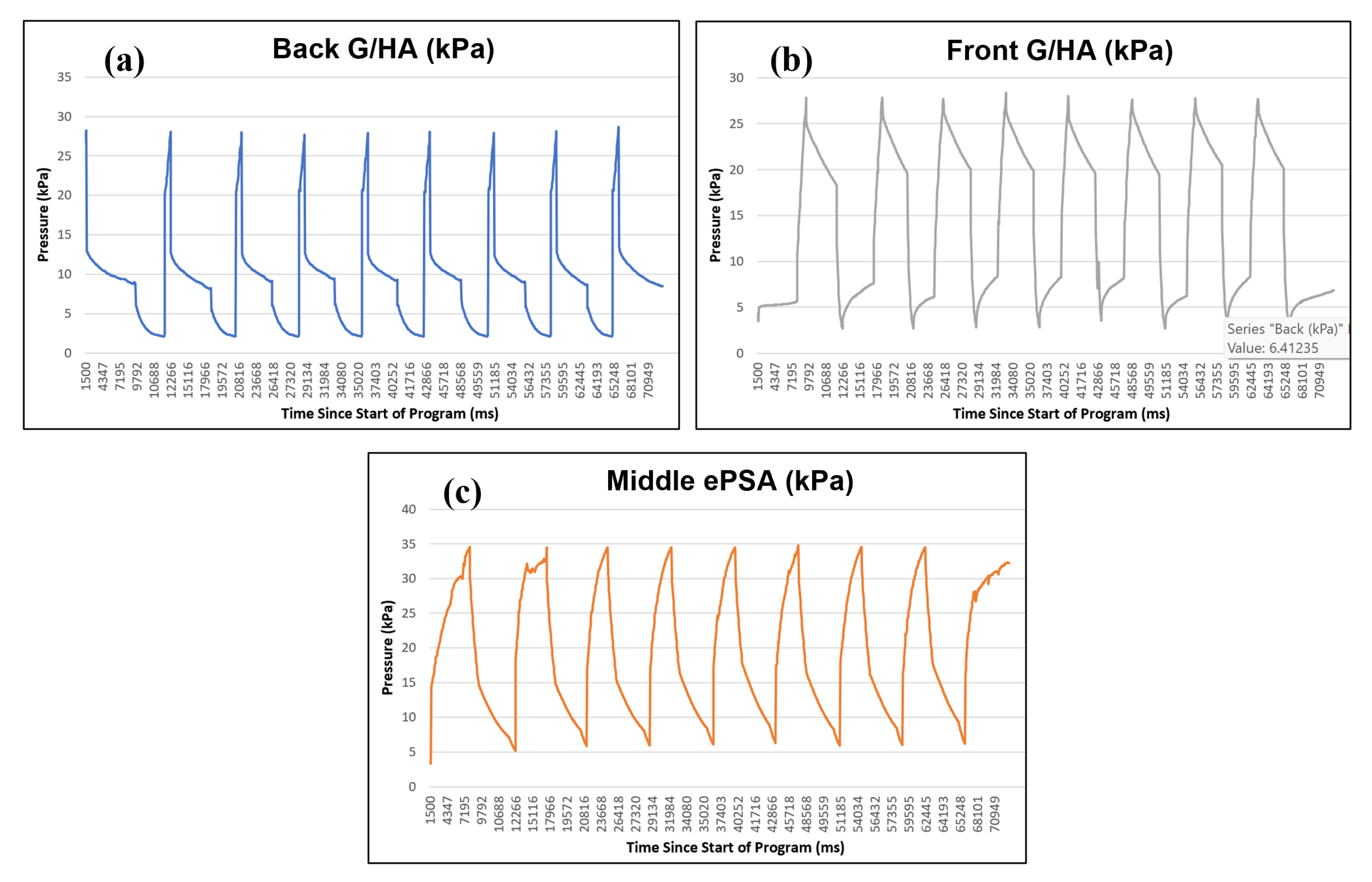
The soft robot had no trouble going either straight down or straight up and was actually faster doing this than when it was moving along a curve. Figure 10a–f shows the snapshots of the soft robot’s locomotion exterior during the up-and-down navigation of a vertical path. The full video of the robot’s locomotion is available in the Supplementary Files, Video S2. The pressure variations in each segment of the soft robot are shown in Figure 11. The results show that the fabric-based air cells can be fully expanded in approximately 500 ms. This rapid response is due to the fact that the input pressure mainly inflates the fabric chamber rather than stretching the material to generate elastic deformation, as opposed to the situation for elastomeric/rubbery materials. The actuation speed is mainly restricted by the flow rate of the pneumatic system, i.e., valves and tubing length, as well as the size of the air cells. The actuation speed can be further enhanced by shortening the length of tubes, using high-frequency solenoid valves, and reducing the effective volume of the chamber. Figure 11c shows the cyclic actuation pattern of the ePSA, with an average time of 2.85 s for full extension and 5.5 s for full contraction. The contraction phase happens passively, whereas the extension is actively driven by pressurized air. Thus, the speed of contraction fully depends on the material’s dynamic response. Additionally, the results show a difference in the pressure profiles of the proximal and distal G/HAs, as shown in Figure 11a,b. During our tuning of the control system’s specific sequences of timing for the locomotion of the soft actuator, as shown in Figure 12, in order to achieve a greater forward speed, we realized that a faster inflation/deflation process of the front G/HA combined with the simultaneous expansion of the ePSA leads to a faster forward movement of the robot, while a slower inflation/deflation of the back G/HA helps with the stability of forward movement without any noticeable slipping back movements during the compression of the ePSA modules. Moreover, in each cycle of locomotion, the front (distal) G/HA is actively pushed by the ePSA while the back (proximal) G/HA is passively pulled by the ePSA, which causes two different time responses and different pressure profiles for the distal and proximal G/HA. This difference in timing is illustrated in Figure 12 using the state number and arrows, in which the length is the relative duration of the transition between the states. The back G/HA has three states during each cycle, while the front G/HA has four states and the ePSA has two states, as labeled by color-coded numbers. The horizontal location between the states of each element shows the relative timing of operation of the distal, proximal, and middle actuators. The results show that the controller was able to provide a consistent cyclic pattern of required pressure for the successful straight down and up locomotion of the soft robot, as shown in Figure 10.
4. Discussion
Cost of Transportation: Compared to conventional (rigid) climbing robots [5], our soft robot has a significantly lower cost of transportation for carrying out similar tasks. For example, CCRobot-I [41] has a total mass of 15 kg and traverses the cable vertically at a speed of 0.05 m/s. For climbing a distance of 1 m, this locomotion requires a power of 7.4 W. While our soft robot, with a total mass of 0.1 kg and a speed of 0.008 m/s, traverses a vertical distance of 1 m with only 0.0079 W. This is a reduction of about 937-fold, which emphasizes the significance of using a light-weight soft body design and soft actuators with a high force-to-weight ratio. Other rigid climbing robots [1] with larger weights and higher speeds need more power to carry out the same task.
Navigation versatility: Most conventional inspection robots are designed and developed for carrying out a specific task with a single locomotion mode that leads to navigating a straight vertical path or close to a vertical path. In contrast, the presented soft robot with inherent compliance and flexibility can navigate various path configurations, such as vertical and curved paths, as demonstrated in this work (see Figure 9 and Figure 10).
Payload: Conventional inspection robots have shown a very high payload capacity, in the range of 8 to 40 kg [1,5,41]; compared to the total mass of the robots, we can estimate a payload-to-weight ratio of about 0.67 to 2. With the current range of actuation pressure, 0–4 psi (0–28.0 kPa), the presented soft robot in this work can carry a payload more than three times its own weight. Although the payload-to-weight ratio exceeds that of conventional robots, the payload capacity is significantly smaller than that of conventional inspection robots. The payload capacity can be increased by increasing the number of air cells and ePSA middle actuators. Note that increasing this actuator will cause an increase in the required pneumatic components and thus increase the robot’s weight as well.
Locomotion performance: Compared to our first soft robot generation [4], the performance of the soft robot locomotion has significantly improved (three-fold increase in average speed). However, the achieved speed (approximately 8.0 mm/s) is still lower than that of conventional inspection robots (between 50 and 300 mm/s). To address this limitation, using a higher actuation pressure, solenoid valves with a higher operation frequency, and active contraction for the ePSA would improve the performance. The difference between the active extension and passive contraction, as shown in Figure 12, causes the need to plan different timings for actuation of the distal and the proximal G/HA, thus achieving slower locomotion. A miniature pressurizing/vacuuming pump enables the soft robot’s active contraction and faster locomotion motion.
5. Conclusions
This paper presents a soft robot that combines soft-body grasping with crawling locomotion to navigate tubular objects. The robot includes proximal and distal modules for grasping around objects and a driving module for bi-directional crawling movement. The robot was made using advanced and conventional manufacturing techniques and was tested in a laboratory setting to navigate a cable. The robot demonstrated its capability to navigate cables in vertical, horizontal, and curved path scenarios, with a three-fold improvement in forward speed compared to the initial design.
In future work, the design and prototyping of shape-morphing soft-bodied mechanisms will be studied to facilitate traversing over or through typical obstacles found on tubular structures while integrating portable sensors with remote/wireless communication for data collection. Additionally, research into the use of miniature pumps and portable batteries will be conducted to enable the operation of the soft robot outside of a laboratory environment. This would result in a portable and functional robot for testing in the field.
Supplementary Materials
The following supporting information can be downloaded at: https://eltnmsu-my.sharepoint.com/:f:/g/personal/mahdihj_nmsu_edu/EnJyTuT2Og1FszZASajpqHsBDvvd3MLiUexz2-GRMfMRLw?e=Pui3GF (accessed on 29 December 2023), Video S1: Downhill and uphill navigation of a curved tubular structure; Video S2: Vertical up and down navigation.
Author Contributions
Conceptualization, N.M. and M.H.-J.; methodology, N.M. and M.H.-J.; software, N.M.; validation, N.M.; formal analysis, N.M.; investigation, N.M. and M.H.-J.; resources, M.H.-J.; data curation, N.M.; writing—original draft preparation, N.M. and M.H.-J.; writing—review and editing, M.H.-J.; visualization, N.M.; supervision, M.H.-J.; project administration, M.H.-J.; funding acquisition, M.H.-J. All authors have read and agreed to the published version of the manuscript.
Funding
The first author, Nicolás Mendoza, was supported by the New Mexico Alliance for Minority Participation (AMP): Undergraduate Research Scholar (URS) funded by National Science Foundation (NSF) grant No. HRD-1826758.
Institutional Review Board Statement
Not applicable.
Informed Consent Statement
Not applicable.
Data Availability Statement
Data will be provided upon request.
Conflicts of Interest
The authors declare no conflicts of interest.
Abbreviations
The following abbreviations are used in this manuscript:
| G/HA | Grabber/holder actuator |
| C.E.T.O.P. | European Fluid Power Committee |
| ePSA | Extensible pneumatic soft actuator |
| SFA | Soft fabric actuator |
| TTI | Time to inflate |
| TTD | Time to deflate |
References
- Fang, G.; Cheng, J. Advances in Climbing Robots for Vertical Structures in the Past Decade: A Review. Biomimetics 2023, 8, 47. [Google Scholar] [CrossRef] [PubMed]
- Katrasnik, J.; Pernus, F.; Likar, B. A survey of mobile robots for distribution power line inspection. IEEE Trans. Power Deliv. 2009, 25, 485–493. [Google Scholar] [CrossRef]
- Katrasnik, J.; Pernus, F.; Likar, B. New robot for power line inspection. In Proceedings of the 2008 IEEE Conference on Robotics, Automation and Mechatronics, Chengdu, China, 21–24 September 2008; IEEE: Piscataway, NJ, USA, 2008; pp. 1195–1200. [Google Scholar]
- Mendoza, N.; Nemati, H.; Haghshenas-Jaryani, M.; Dehghan-Niri, E. An Inflatable Soft Crawling Robot with Nondestructive Testing Capability for Overhead Power Line Inspection. In Proceedings of the ASME International Mechanical Engineering Congress and Exposition, Columbus, OH, USA, 30 October–3 November 2022; American Society of Mechanical Engineers: New York, NY, USA, 2022; Volume 86670, p. V005T07A021. [Google Scholar]
- Fang, Y.; Wang, S.; Bi, Q.; Cui, D.; Yan, C. Design and Technical Development of Wall-Climbing Robots: A Review. J. Bionic Eng. 2022, 19, 877–901. [Google Scholar] [CrossRef]
- Megalingam, R.K.; Sakthiprasad, K.; Sreekanth, M.; Vivek, G.V. A survey on robotic coconut tree climbers–existing methods and techniques. IOP Conf. Ser. Mater. Sci. Eng. 2017, 225, 012201. [Google Scholar] [CrossRef]
- Seo, T.; Jeon, Y.; Park, C.; Kim, J. Survey on Glass And Façade-Cleaning Robots: Climbing Mechanisms, Cleaning Methods, and Applications. Int. J. Precis. Eng. Manuf.-Green Technol. 2019, 6, 367–376. [Google Scholar] [CrossRef]
- Cai, S.; Ma, Z.; Skibniewski, M.J.; Bao, S. Construction automation and robotics for high-rise buildings over the past decades: A comprehensive review. Adv. Eng. Inform. 2019, 42, 100989. [Google Scholar] [CrossRef]
- Bogue, R. Climbing robots: Recent research and emerging applications. Ind. Robot. Int. J. Robot. Res. Appl. 2019, 46, 721–727. [Google Scholar] [CrossRef]
- Hou, S.; Dong, B.; Wang, H.; Wu, G. Inspection of surface defects on stay cables using a robot and transfer learning. Autom. Constr. 2020, 119, 103382. [Google Scholar] [CrossRef]
- Shah, D.; Yang, B.; Kriegman, S.; Levin, M.; Bongard, J.; Kramer-Bottiglio, R. Shape Changing Robots: Bioinspiration, Simulation, and Physical Realization. Adv. Mater. 2021, 33, 2002882. [Google Scholar] [CrossRef]
- Cianchetti, M.; Calisti, M.; Margheri, L.; Kuba, M.; Laschi, C. Bioinspired locomotion and grasping in water: The soft eight-arm OCTOPUS robot. Bioinspir. Biomim. 2015, 10, 035003. [Google Scholar] [CrossRef] [PubMed]
- Lopez, M.; Haghshenas-Jaryani, M. A Muscle-Driven Mechanism for Locomotion of Snake-Robots. Automation 2022, 3, 1–26. [Google Scholar] [CrossRef]
- Lopez, M.; Haghshenas-Jaryani, M. A Study of Energy-Efficient and Optimal Locomotion in a Pneumatic Artificial Muscle-Driven Snake Robot. Robotics 2023, 12, 89. [Google Scholar] [CrossRef]
- Yin, A.; Lin, H.C.; Thelen, J.; Mahner, B.; Ranzani, T. Combining locomotion and grasping functionalities in soft robots. Adv. Intell. Syst. 2019, 1, 1900089. [Google Scholar] [CrossRef]
- Sanfilippo, F. Combining grasping with adaptive path following and locomotion for modular snake robots. Int. J. Mech. Eng. Robot. Res. 2022, 11, 59–65. [Google Scholar] [CrossRef]
- Salvietti, G.; Zhang, H.X.; Gonzalez-Gòmez, J.; Prattichizzo, D.; Zhang, J.W. Task priority grasping and locomotion control of modular robot. In Proceedings of the 2009 IEEE International Conference on Robotics and Biomimetics (ROBIO), Guilin, China, 19–23 December 2009; pp. 1069–1074. [Google Scholar] [CrossRef]
- Asfour, T.; Borrás, J.; Mandery, C.; Kaiser, P.; Aksoy, E.E.; Grotz, M. On the dualities between grasping and whole-body loco-manipulation tasks. Robot. Res. 2018, 2, 305–322. [Google Scholar]
- Chen, S.; Cao, Y.; Sarparast, M.; Yuan, H.; Dong, L.; Tan, X.; Cao, C. Soft Crawling Robots: Design, Actuation, and Locomotion. Adv. Mater. Technol. 2020, 5, 1900837. [Google Scholar] [CrossRef]
- Zhang, B.; Fan, Y.; Yang, P.; Cao, T.; Liao, H. Worm-Like Soft Robot for Complicated Tubular Environments. Soft Robot. 2019, 6, 399–413. [Google Scholar] [CrossRef]
- Chattopadhyay, P.; Ghoshal, S.; Majumder, A.; Dikshit, H. Locomotion Methods of Pipe Climbing robots: A Review. J. Eng. Sci. Technol. Rev. 2018, 11, 154–165. [Google Scholar] [CrossRef]
- Roh, S.g.; Choi, H.R. Differential-drive in-pipe robot for moving inside urban gas pipelines. IEEE Trans. Robot. 2005, 21, 1–17. [Google Scholar]
- Yousef, B.F.; Bastaki, N. Worm robot with dynamic adaptation to pipe diameter for in-pipe inspection. Int. J. Eng. Innov. Technol. 2014, 3, 286–292. [Google Scholar]
- Xu, Z.L.; Lu, S.; Yang, J.; Feng, Y.H.; Shen, C.T. A wheel-type in-pipe robot for grinding weld beads. Adv. Manuf. 2017, 5, 182–190. [Google Scholar] [CrossRef]
- Li, P.; Ma, S.; Lyu, C.; Jiang, X.; Liu, Y. Energy-efficient control of a screw-drive pipe robot with consideration of actuator’s characteristics. Robot. Biomim. 2016, 3, 11. [Google Scholar] [CrossRef]
- Wakimoto, S.; Nakajima, J.; Takata, M.; Kanda, T.; Suzumori, K. A micro snake-like robot for small pipe inspection. In Proceedings of the MHS2003, 2003 International Symposium on Micromechatronics and Human Science (IEEE Cat. No. 03TH8717), Nagoya, Japan, 19–22 October 2003; IEEE: Piscataway, NJ, USA, 2003; pp. 303–308. [Google Scholar]
- Cianciarulo, F.; Garbulinski, J.; Chambers, J.; Pillsbury, T.; Wereley, N.; Cross, A.; Trivedi, D. Analysis of an anchoring muscle for pipe crawling robot. In Proceedings of the SPIE Smart Structures + Nondestructive Evaluation, Long Beach, CA, USA, 12–17 March 2023; Volume 12481, p. 1248108. [Google Scholar] [CrossRef]
- Han, S.C.; An, J.; Moon, H. A remotely controlled out-pipe climbing robot. In Proceedings of the 2013 10th International Conference on Ubiquitous Robots and Ambient Intelligence (URAI), Jeju, Republic of Korea, 30 October–2 November 2013; IEEE: Piscataway, NJ, USA, 2013; p. 126. [Google Scholar]
- Baghani, A.; Ahmadabadi, M.N.; Harati, A. Kinematics modeling of a wheel-based pole climbing robot (UT-PCR). In Proceedings of the Proceedings of the 2005 IEEE international Conference on Robotics and Automation, Barcelona, Spain, 18–22 April 2005; IEEE: Piscataway, NJ, USA, 2005; pp. 2099–2104. [Google Scholar]
- Mampel, J.; Gerlach, K.; Schilling, C.; Witte, H. A modular robot climbing on pipe-like structures. In Proceedings of the 2009 4th International Conference on Autonomous Robots and Agents, Wellington, New Zealand, 10–12 February 2009; IEEE: Piscataway, NJ, USA, 2009; pp. 87–91. [Google Scholar]
- Adams, W. A Novel, Bio-Inspired, Soft Robot for Water Pipe Inspection. Master’s Thesis, Arizona State University, Tempe, AZ, USA, 2019. [Google Scholar]
- Savidge, J.A.; Seibert, T.F.; Kastner, M.; Jayne, B.C. Lasso locomotion expands the climbing repertoire of snakes. Curr. Biol. 2021, 31, R7–R8. [Google Scholar] [CrossRef] [PubMed]
- Jayne, B.C. What defines different modes of snake locomotion? Integr. Comp. Biol. 2020, 60, 156–170. [Google Scholar] [CrossRef]
- Jayne, B.C.; Newman, S.J.; Zentkovich, M.M.; Berns, H.M. Why arboreal snakes should not be cylindrical: Body shape, incline and surface roughness have interactive effects on locomotion. J. Exp. Biol. 2015, 218, 3978–3986. [Google Scholar] [CrossRef]
- O’Neill, C.T.; McCann, C.M.; Hohimer, C.J.; Bertoldi, K.; Walsh, C.J. Unfolding Textile-Based Pneumatic Actuators for Wearable Applications. Soft Robot. 2021, 9, 163–172. [Google Scholar] [CrossRef] [PubMed]
- Nguyen, P.H.; Zhang, W. Design and Computational Modeling of Fabric Soft Pneumatic Actuators for Wearable Assistive Devices. Sci. Rep. 2020, 10, 9638. [Google Scholar] [CrossRef]
- Zhang, Z.; Long, Y.; Chen, G.; Wu, Q.; Wang, H.; Jiang, H. Soft and lightweight fabric enables powerful and high-range pneumatic actuation. Sci. Adv. 2024, 9, eadg1203. [Google Scholar] [CrossRef] [PubMed]
- Khin, P.M.; Yap, H.K.; Ang, M.H.; Yeow, C.H. Fabric-based actuator modules for building soft pneumatic structures with high payload-to-weight ratio. In Proceedings of the 2017 IEEE/RSJ International Conference on Intelligent Robots and Systems (IROS), Vancouver, BC, Canada, 24–28 September 2017; pp. 2744–2750. [Google Scholar] [CrossRef]
- Niiyama, R.; Sun, X.; Sung, C.; An, B.; Rus, D.; Kim, S. Pouch Motors: Printable Soft Actuators Integrated with Computational Design. Soft Robot. 2015, 2, 59–70. [Google Scholar] [CrossRef]
- Lee, H.; Oh, N.; Rodrigue, H. Expanding Pouch Motor Patterns for Programmable Soft Bending Actuation: Enabling Soft Robotic System Adaptations. IEEE Robot. Autom. Mag. 2020, 27, 65–74. [Google Scholar] [CrossRef]
- Zheng, Z.; Hu, S.; Ding, N. A Biologically Inspired Cable Climbing Robot: CCRobot—Design and Implementation. In Proceedings of the 2018 IEEE International Conference on Robotics and Biomimetics (ROBIO), Kuala Lumpur, Malaysia, 12–15 December 2018; pp. 2354–2359. [Google Scholar] [CrossRef]
Figure 1.
A natural snake climbs a tree through a repetitive movement that includes grasping and contraction of its body. Three phases of climbing: (a) after full body contraction, (b) grasping at the proximal segment and extension of the body, (c) grasping at both proximal and distal ends and beginning of contraction [32]; and (d) the presented bioinspired soft grasping and crawling locomotor robot with two grasping elements at the proximal and distal ends marked by red boxes as well as an extension/contraction element at the middle segment marked by a blue box.

Figure 2.
A schematic demonstrating the sequences of the locomotion of the soft robot, including body grasping/releasing and extension/contraction.
Figure 2.
A schematic demonstrating the sequences of the locomotion of the soft robot, including body grasping/releasing and extension/contraction.

Figure 3.
A single SFA air cell (a) before inflation and (b) after inflation; (c) forces acting on SFA during the contact with exterior of a tubular structure, and (d) examples of the G/HA element with three and four air cells conforming around the exterior of a tubular structure.
Figure 3.
A single SFA air cell (a) before inflation and (b) after inflation; (c) forces acting on SFA during the contact with exterior of a tubular structure, and (d) examples of the G/HA element with three and four air cells conforming around the exterior of a tubular structure.

Figure 4.
A prototype of the soft robot, including body grasping/releasing and extension/contraction modules.
Figure 4.
A prototype of the soft robot, including body grasping/releasing and extension/contraction modules.

Figure 5.
Extensible pneumatic soft actuator (ePSA): (a) 3D-printed casting mold for making (b) untrimmed elastomer-based soft actuator right after demolding, (c) inflated soft actuator, (d) ePSA reinforced with Kevlar line, (e) ePSA reinforced with Super Slick V2 10 lb weight test (fishing line), and (f) ePSA reinforced with Super Slick V2 20 lb weight test (fishing line).

Figure 6.
Electro-pneumatic controller hardware for operation of the soft crawling robot.

Figure 7.
Schematic of the controller diagram.

Figure 8.
Comparison of the displacement versus actuation pressure for three different variations of ePSA.
Figure 8.
Comparison of the displacement versus actuation pressure for three different variations of ePSA.

Figure 9.
Snapshots of locomotion of the soft inflatable crawling robot (a–e) downhill and (e–i) uphill, i.e., traversing a curved tubular path.
Figure 9.
Snapshots of locomotion of the soft inflatable crawling robot (a–e) downhill and (e–i) uphill, i.e., traversing a curved tubular path.

Figure 10.
Snapshots of locomotion of the soft inflatable crawling robot vertically (a–f) from up to down, i.e., traversing a vertical tubular path.
Figure 10.
Snapshots of locomotion of the soft inflatable crawling robot vertically (a–f) from up to down, i.e., traversing a vertical tubular path.

Figure 11.
Measured pressure of the three soft segments of the crawling robot during its cyclic locomotion.
Figure 11.
Measured pressure of the three soft segments of the crawling robot during its cyclic locomotion.

Figure 12.
Comparison of timing sequences of actuation pressure of the three soft segments of the crawling robot during its cyclic locomotion. States of pressure actuation are marked by numbers for each segment.
Figure 12.
Comparison of timing sequences of actuation pressure of the three soft segments of the crawling robot during its cyclic locomotion. States of pressure actuation are marked by numbers for each segment.

Disclaimer/Publisher’s Note: The statements, opinions and data contained in all publications are solely those of the individual author(s) and contributor(s) and not of MDPI and/or the editor(s). MDPI and/or the editor(s) disclaim responsibility for any injury to people or property resulting from any ideas, methods, instructions or products referred to in the content. |
© 2024 by the authors. Licensee MDPI, Basel, Switzerland. This article is an open access article distributed under the terms and conditions of the Creative Commons Attribution (CC BY) license (https://creativecommons.org/licenses/by/4.0/).
Share and Cite
MDPI and ACS Style
Mendoza, N.; Haghshenas-Jaryani, M. Combined Soft Grasping and Crawling Locomotor Robot for Exterior Navigation of Tubular Structures. Machines 2024, 12, 157. https://0-doi-org.brum.beds.ac.uk/10.3390/machines12030157
AMA Style
Mendoza N, Haghshenas-Jaryani M. Combined Soft Grasping and Crawling Locomotor Robot for Exterior Navigation of Tubular Structures. Machines. 2024; 12(3):157. https://0-doi-org.brum.beds.ac.uk/10.3390/machines12030157
Chicago/Turabian StyleMendoza, Nicolás, and Mahdi Haghshenas-Jaryani. 2024. "Combined Soft Grasping and Crawling Locomotor Robot for Exterior Navigation of Tubular Structures" Machines 12, no. 3: 157. https://0-doi-org.brum.beds.ac.uk/10.3390/machines12030157
Note that from the first issue of 2016, this journal uses article numbers instead of page numbers. See further details here.