
Blaise Pascal’s Mechanical Calculator: Geometric Modelling and Virtual Reconstruction

 ,
,  , and
, and 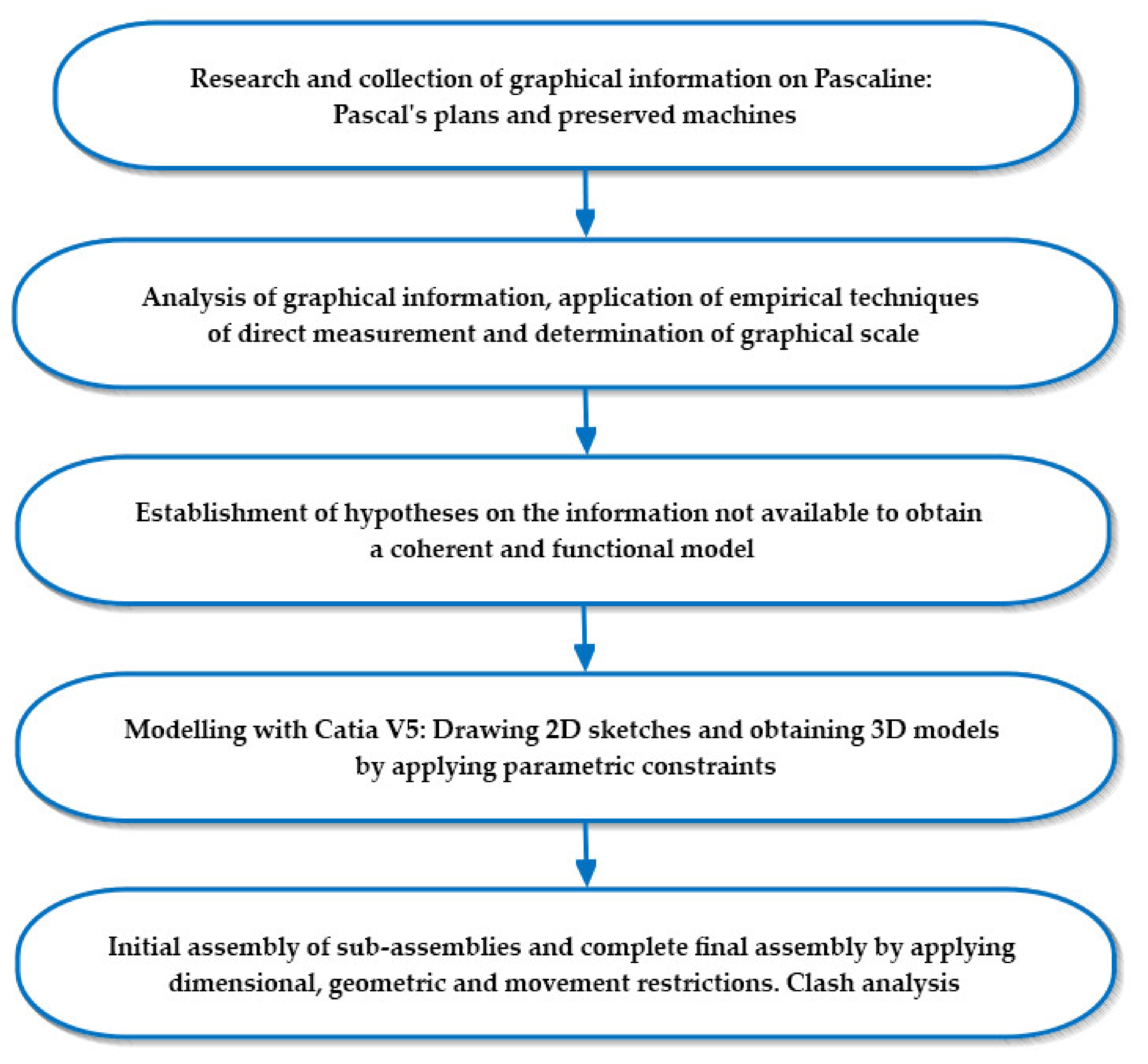
Abstract
:1. Introduction
- The possibility of developing user interaction applications that allow knowing the operation of the invention, detailed knowledge of each of its components or the materials from which they were manufactured.
- The possibility of incorporating its WebGL model into a website.
- The possibility of obtaining realistic virtual recreations for public display or printing said 3D CAD model using additive manufacturing techniques.
2. Materials and Methods
3. Results and Discussion
3.1. Considerations and Operation
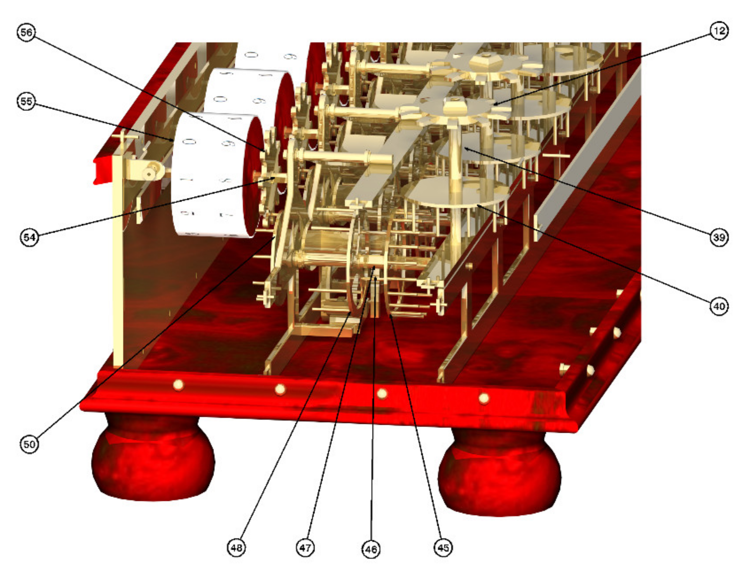
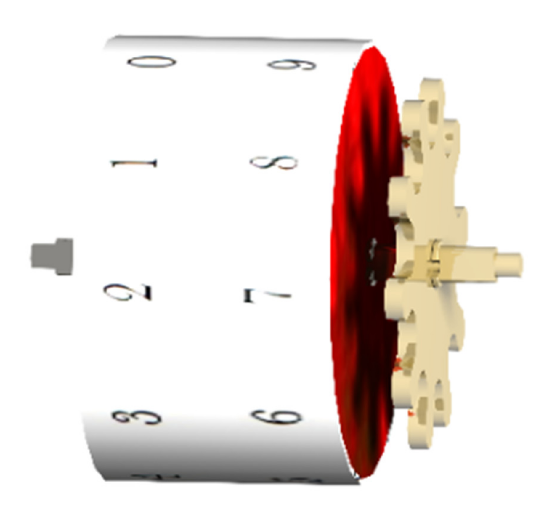
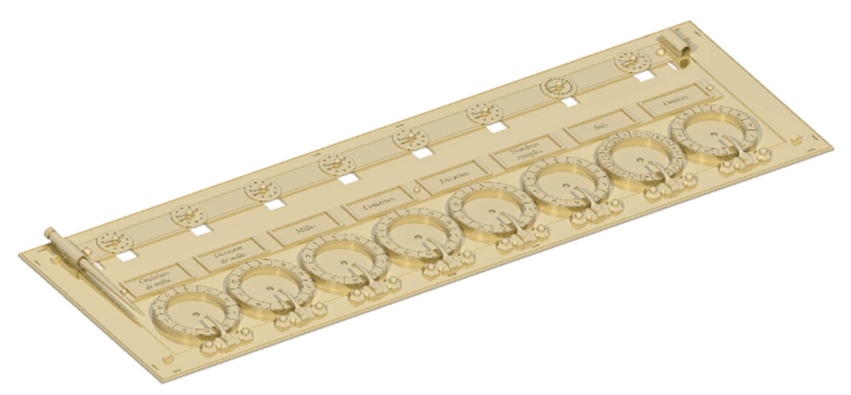
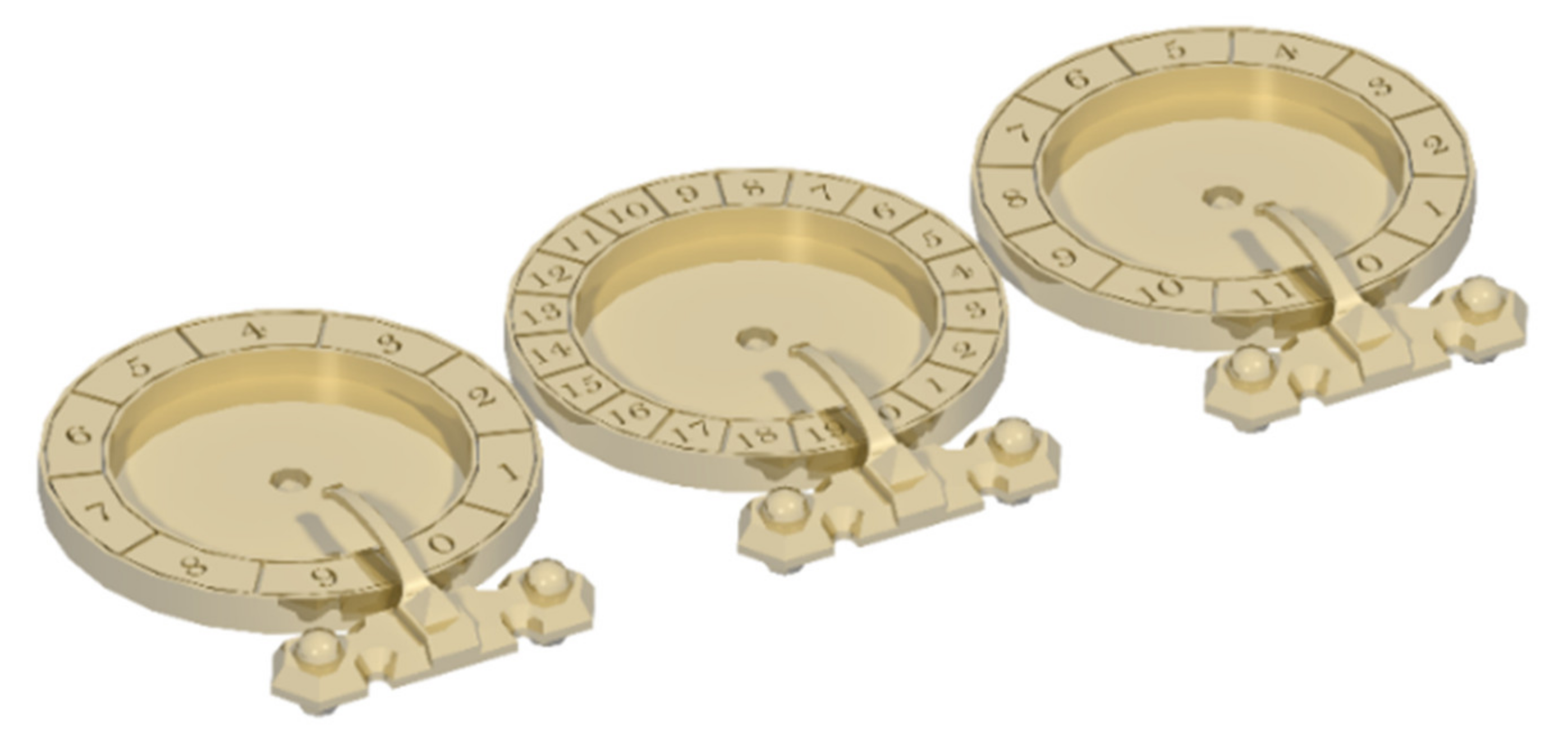
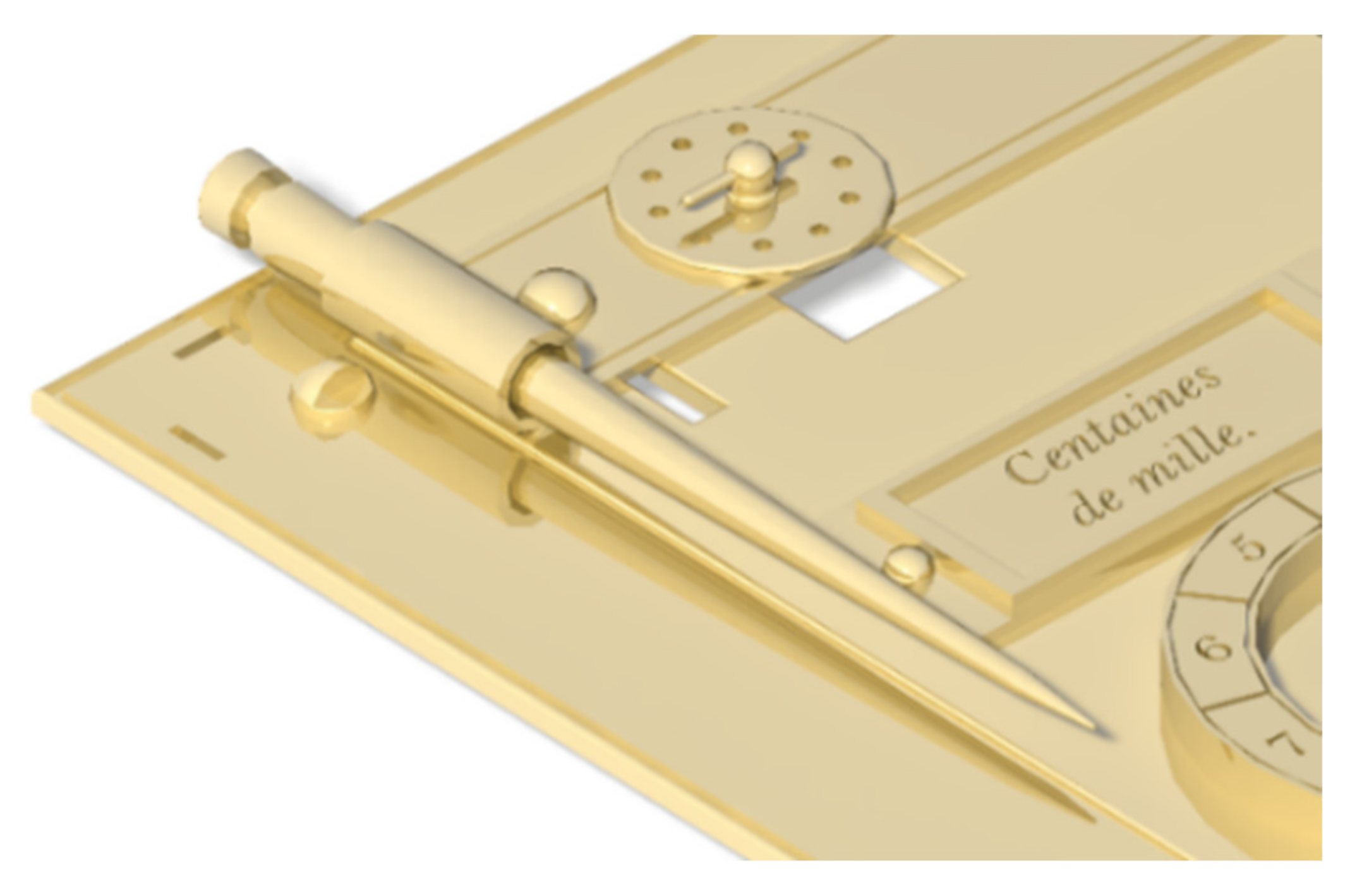
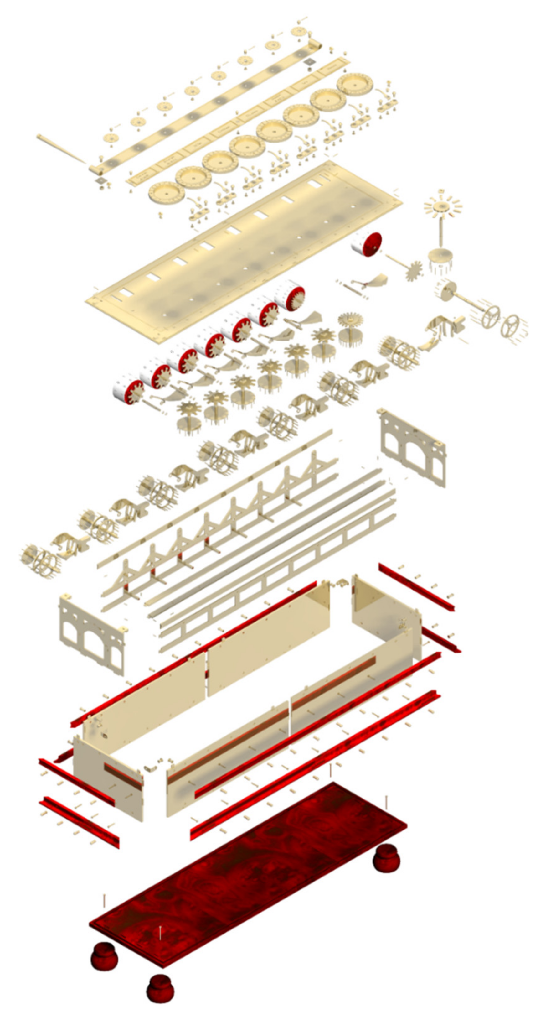
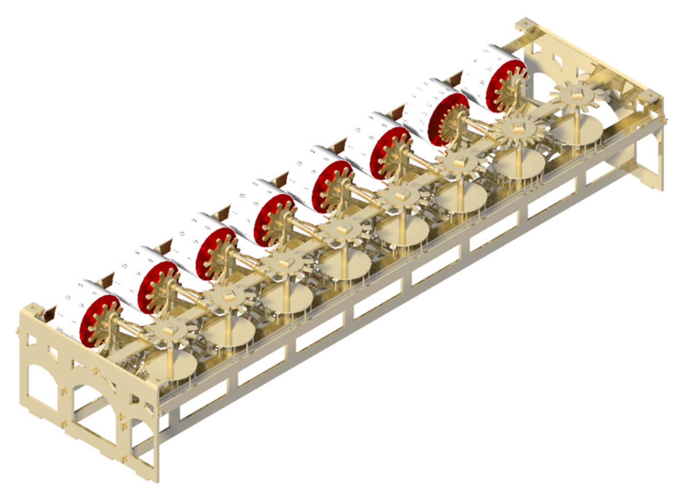
3.2. Modelling of Elements and Assembly of Subsets
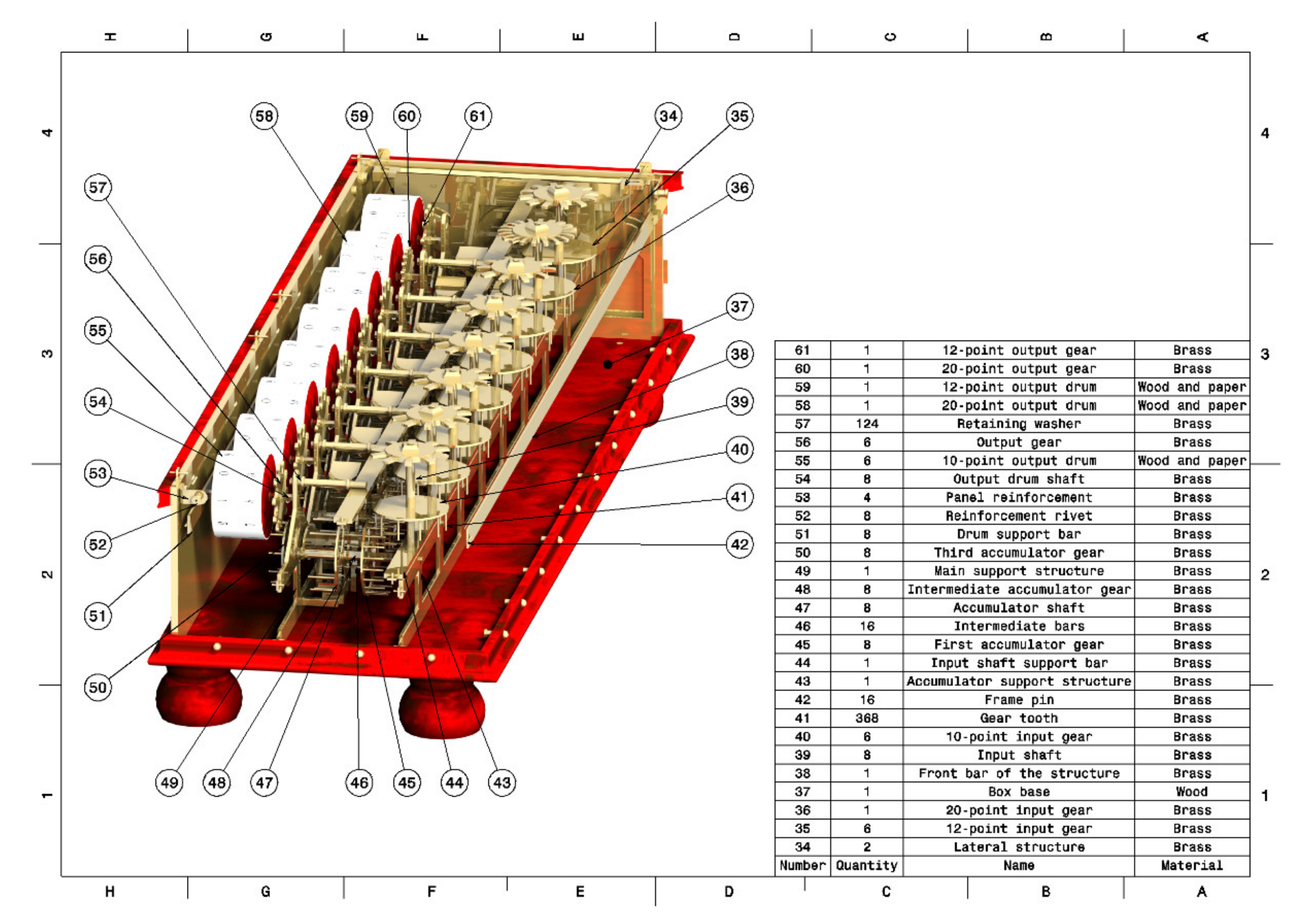
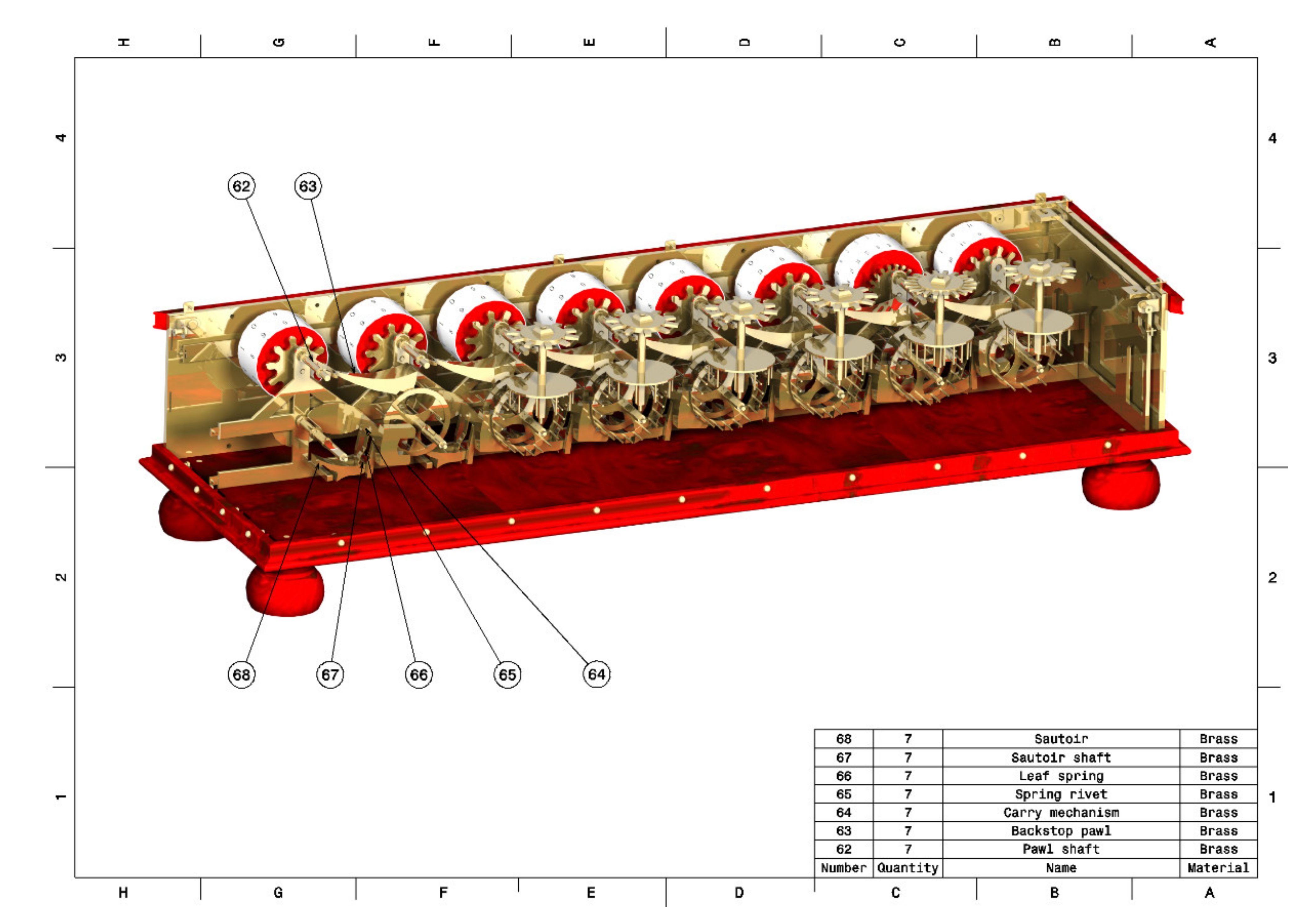
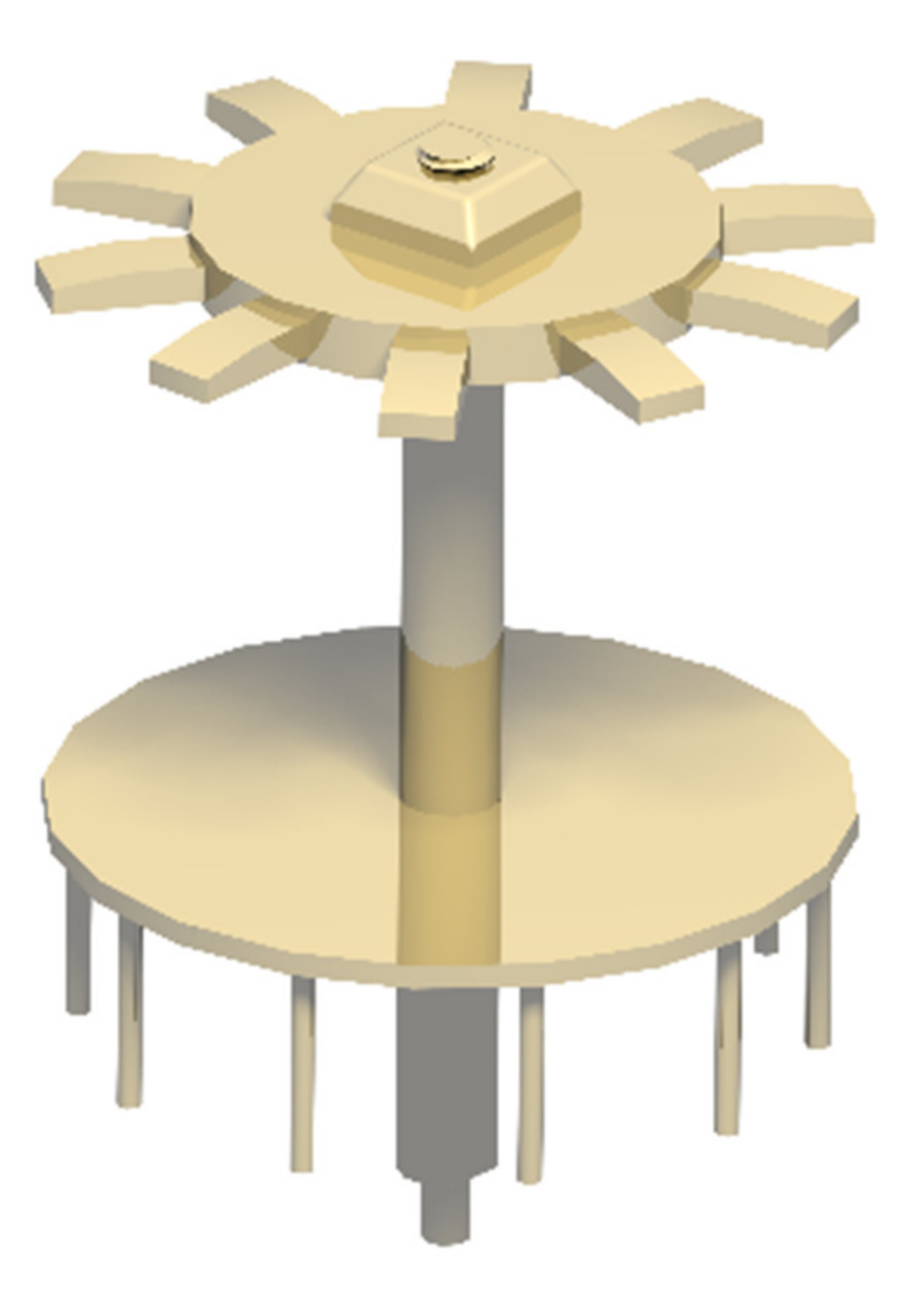
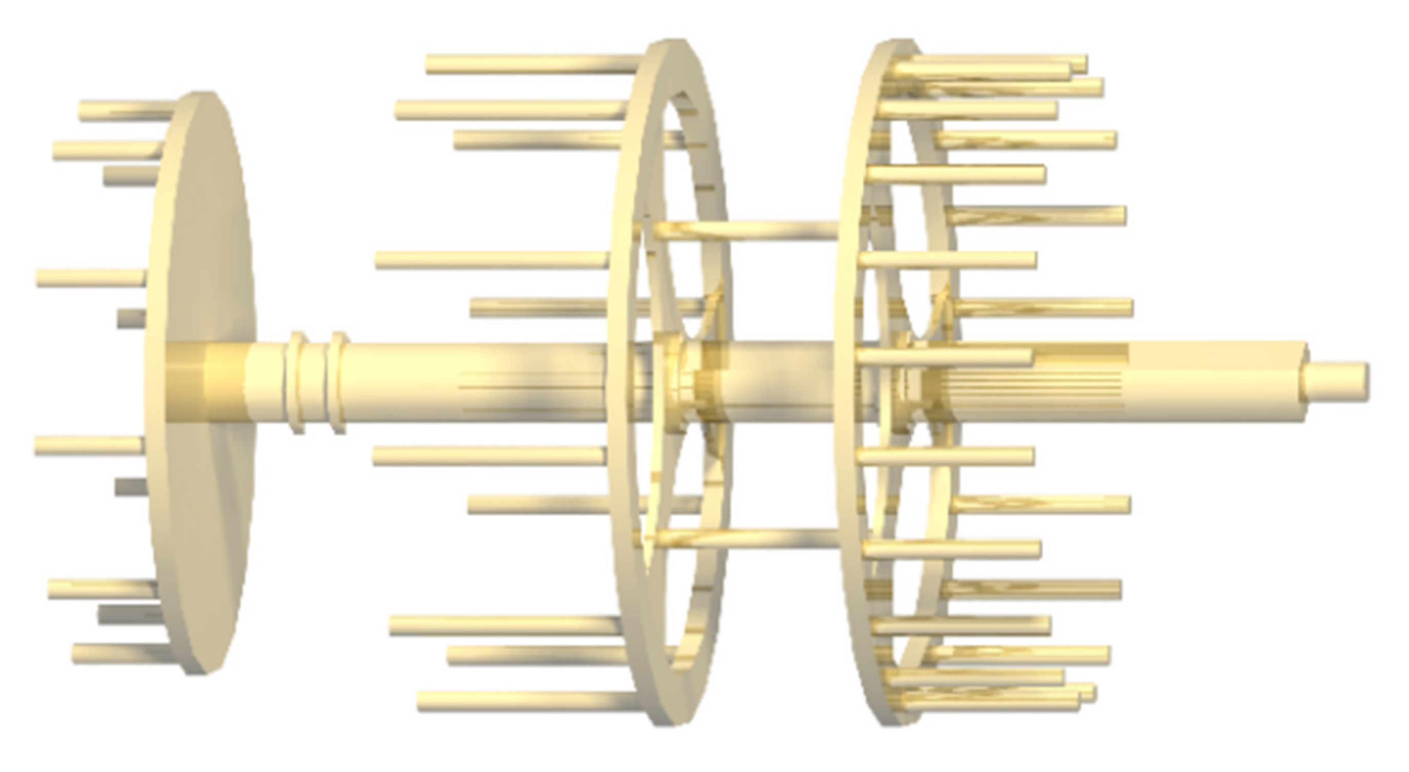
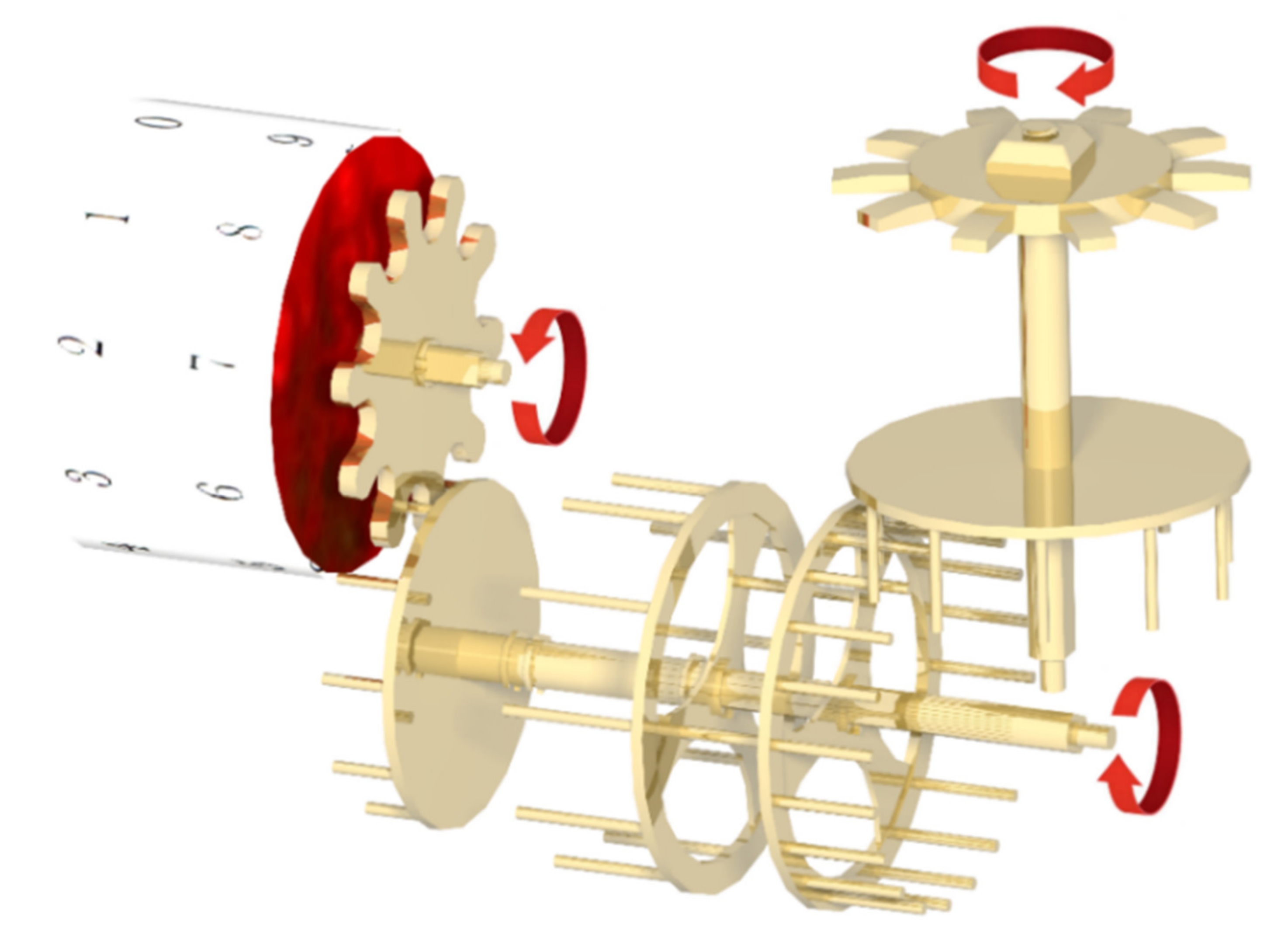
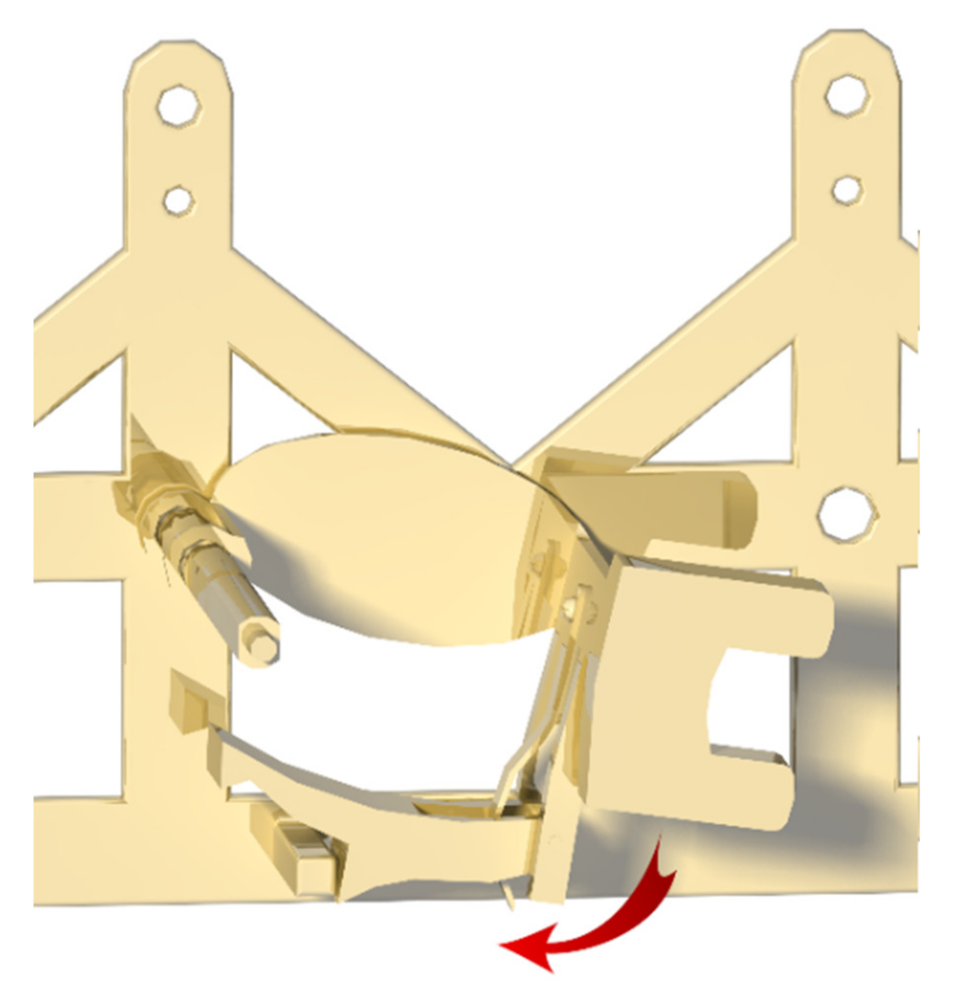
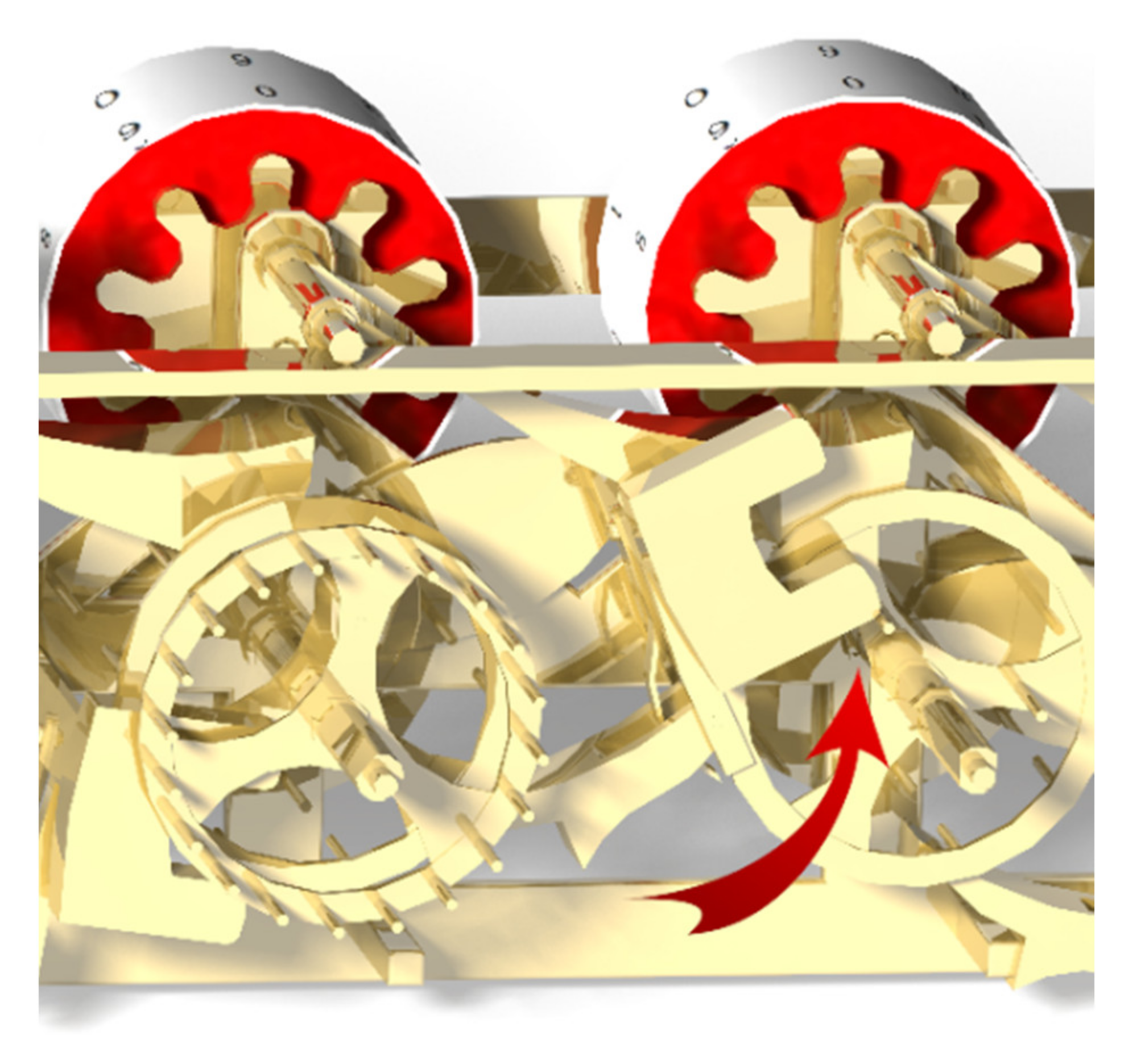
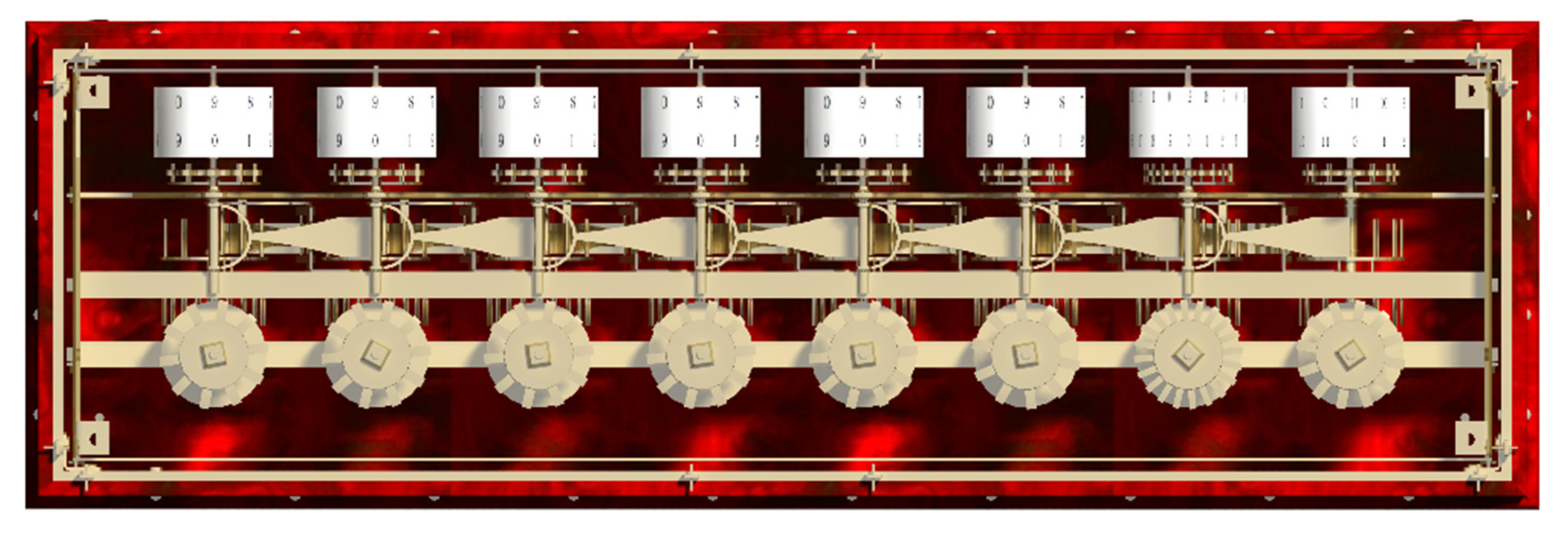
3.2.1. Modelling the Internal Mechanism
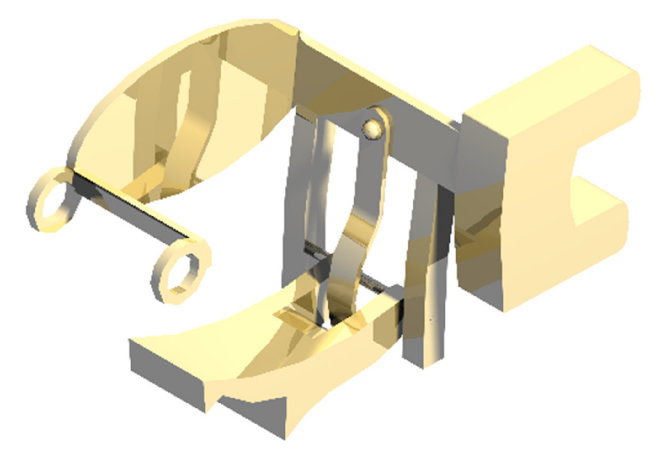
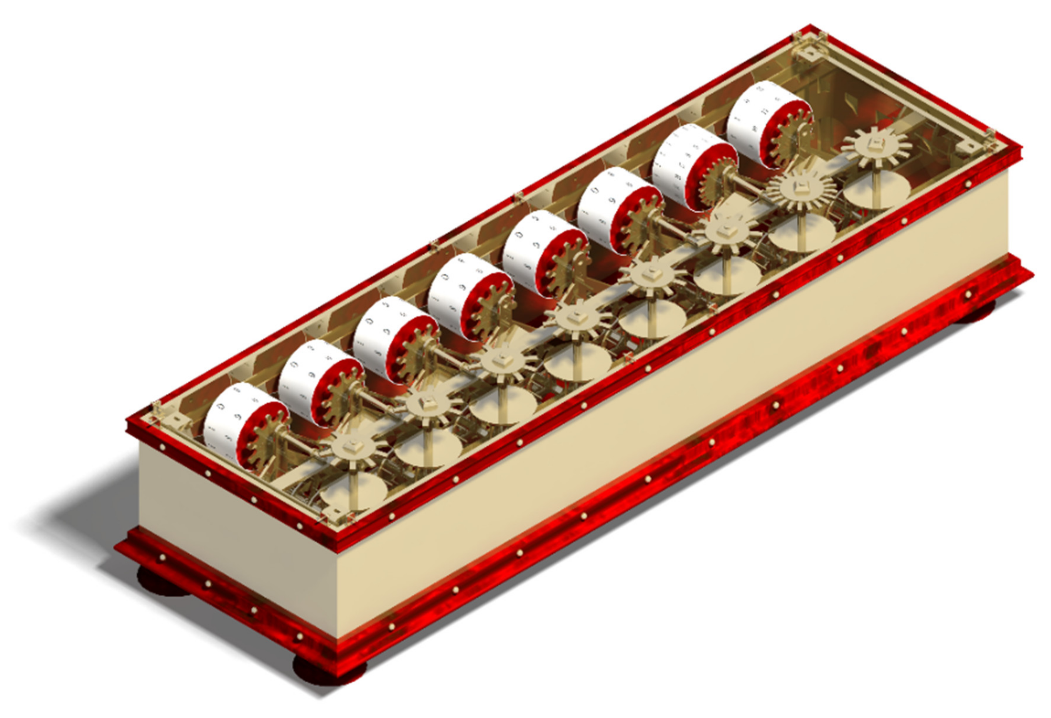
3.2.2. Modelling of the Structure
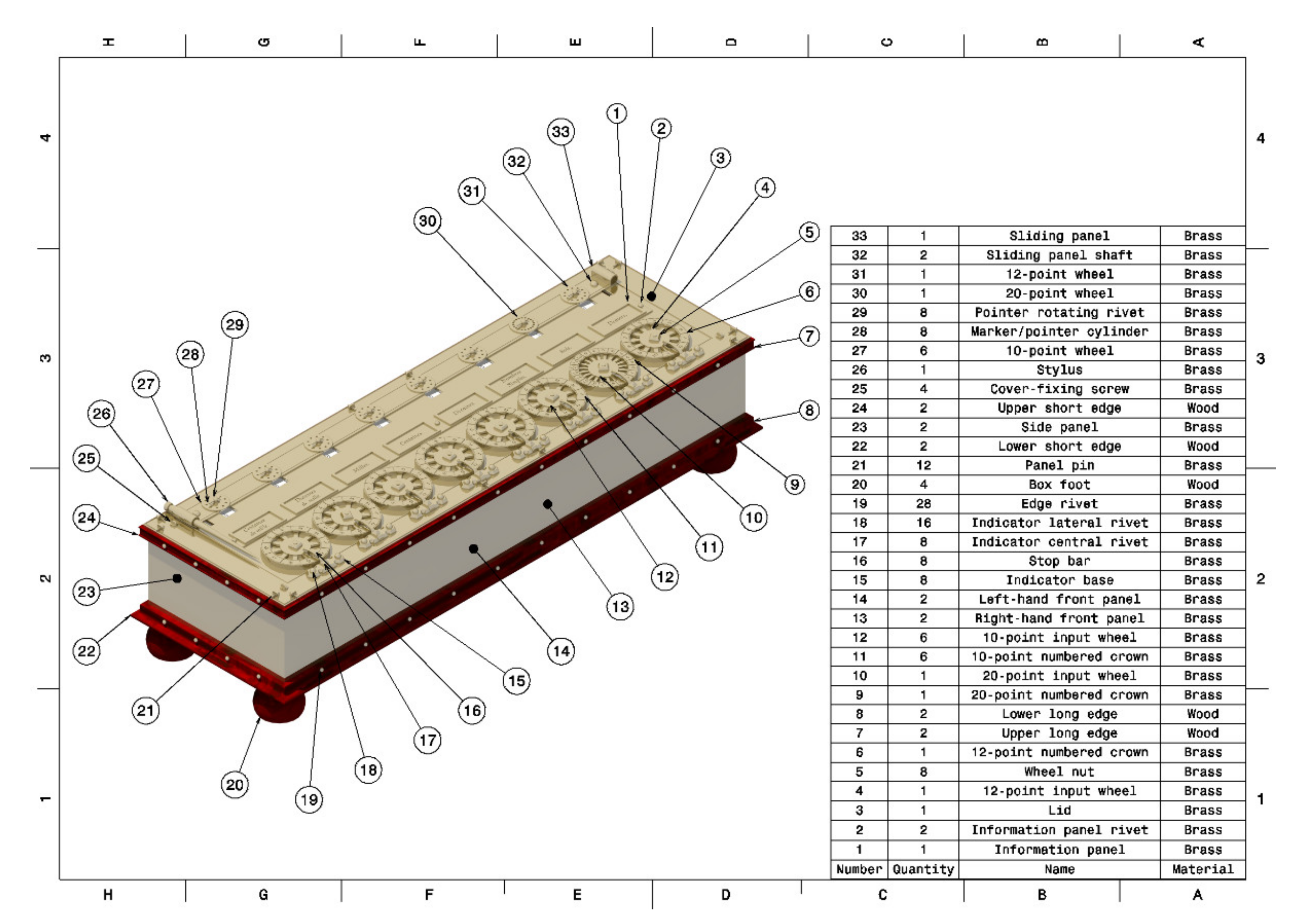
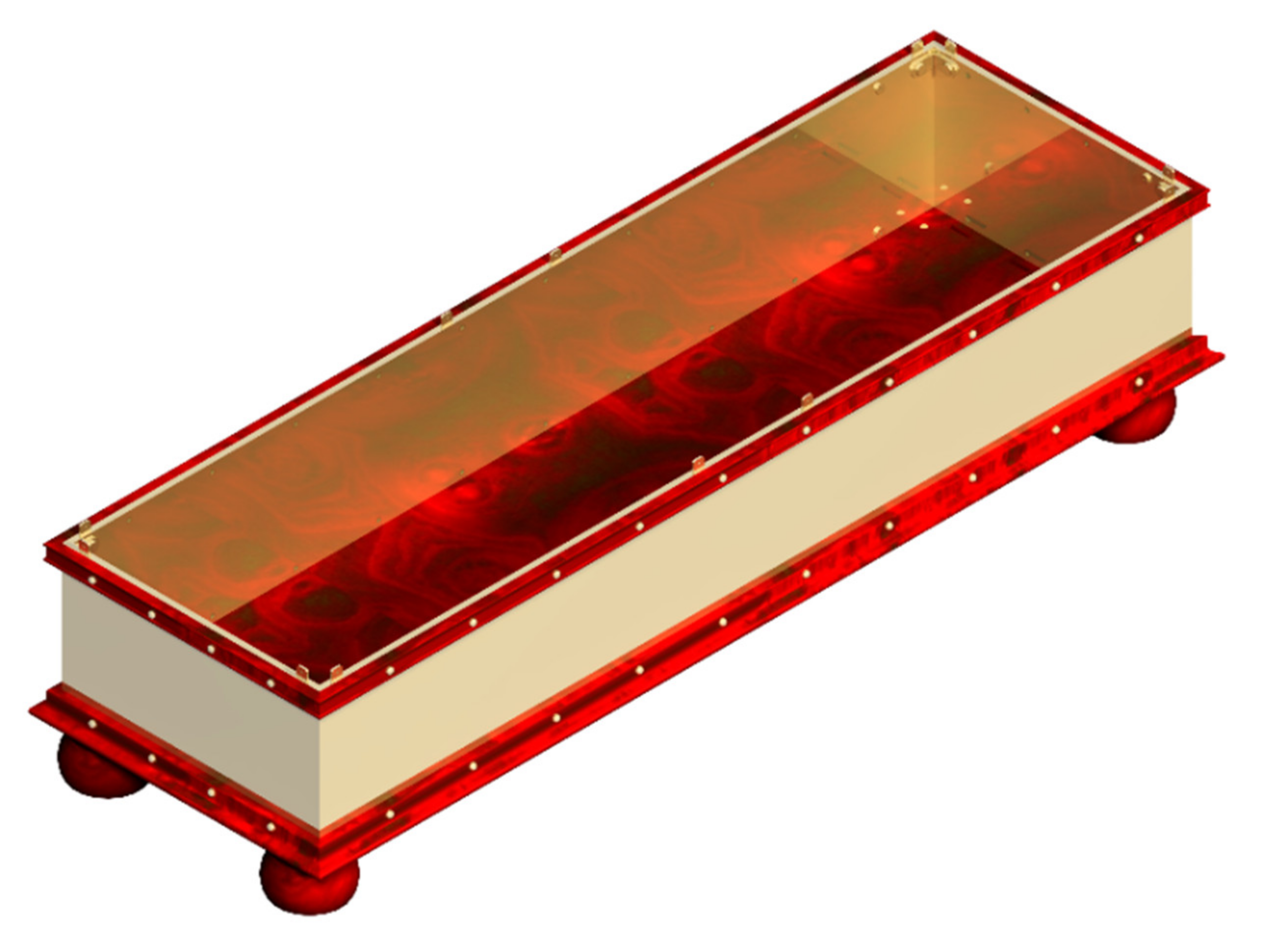
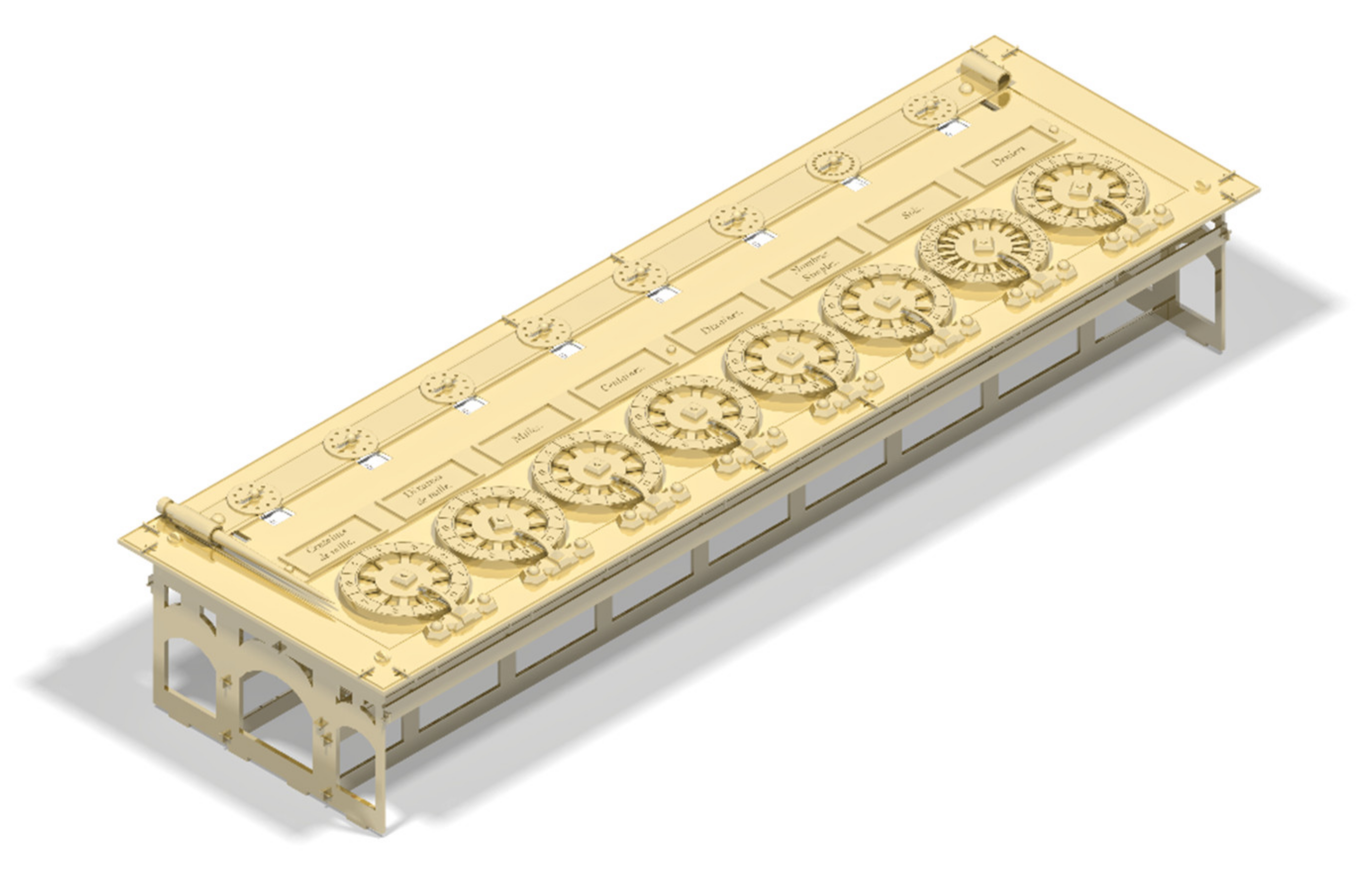
3.2.3. Modelling of the External Part
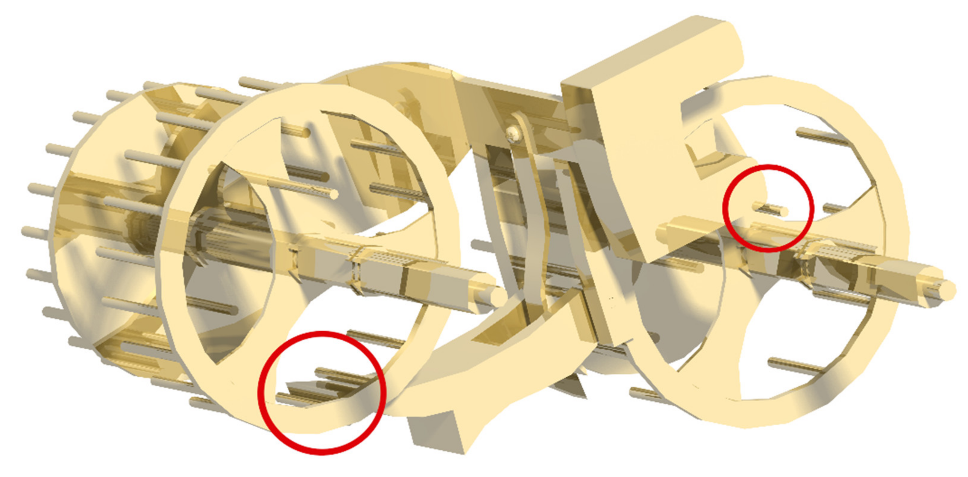
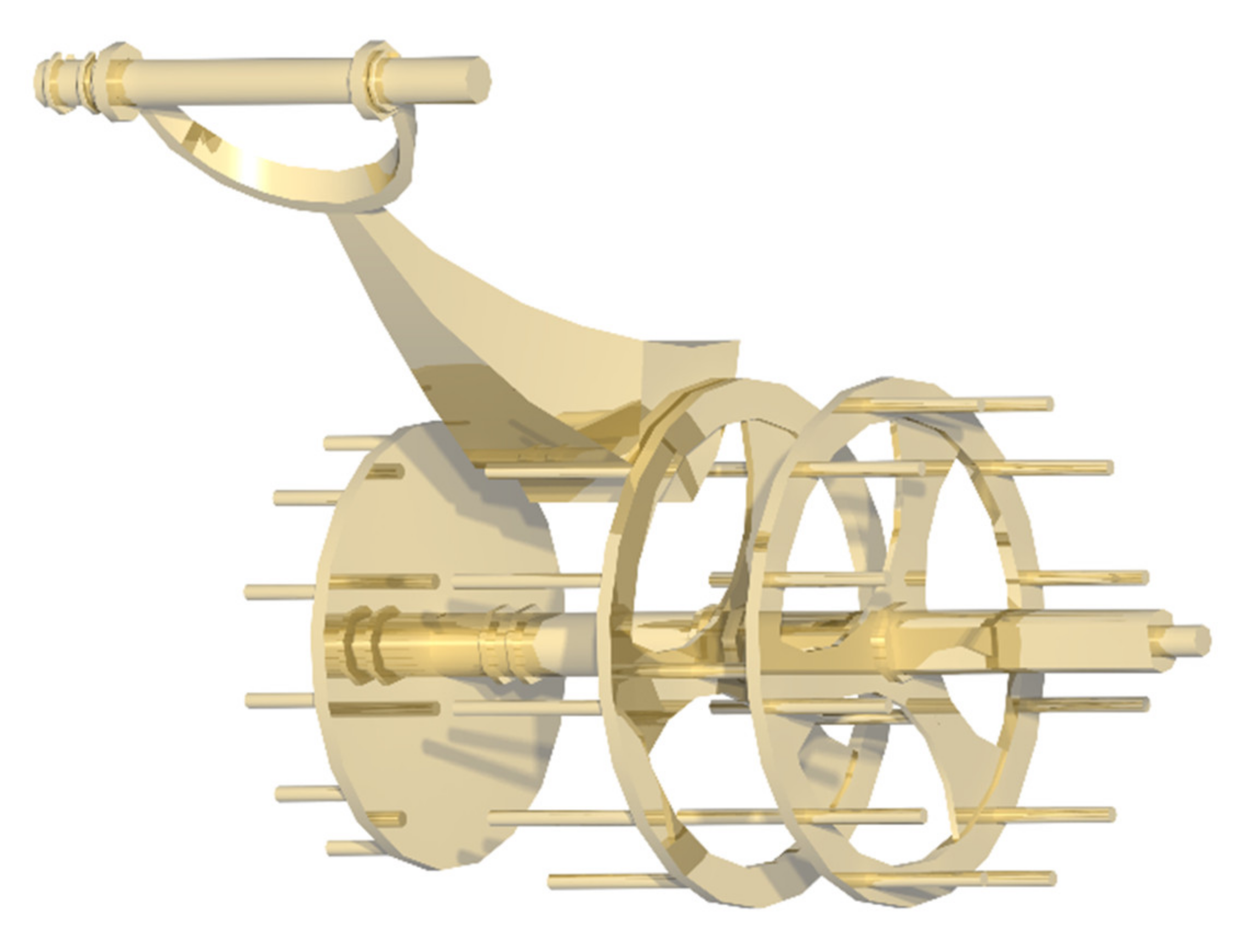
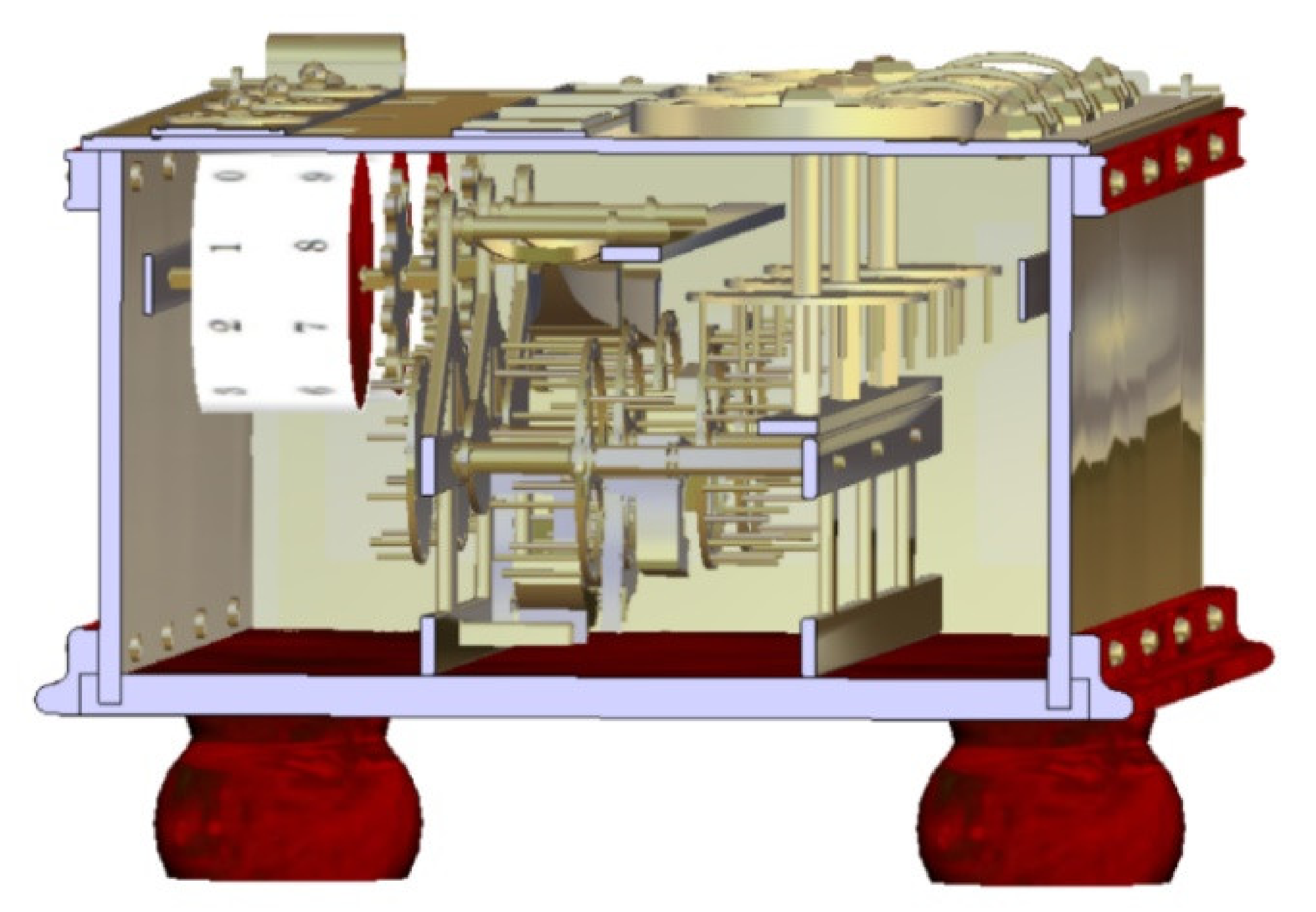
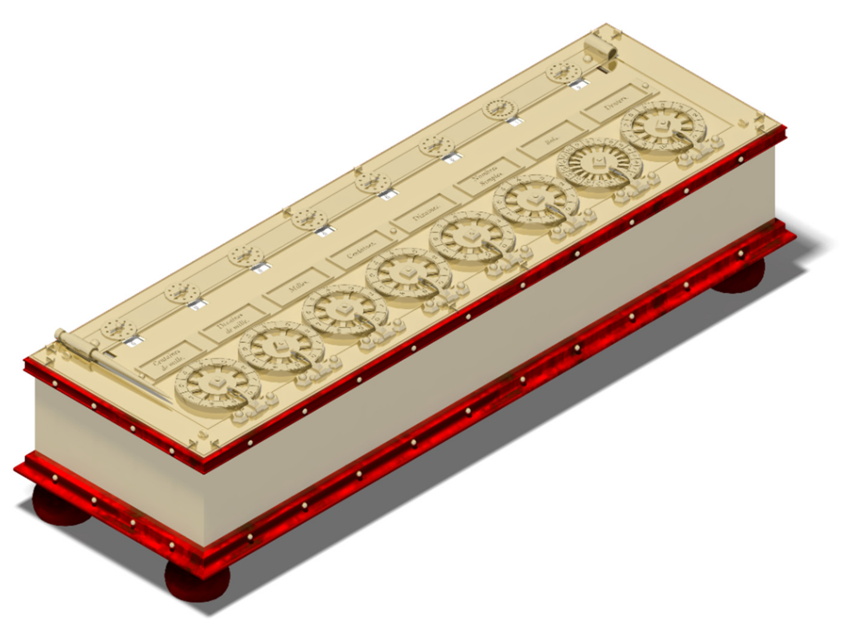
3.3. Final Assembly
4. Conclusions
Author Contributions
Funding
Institutional Review Board Statement
Informed Consent Statement
Data Availability Statement
Acknowledgments
Conflicts of Interest
References
- Pascal, B. Obra Completa; Villar Ezcurra, A., Ed.; Gredos: Madrid, Spain, 2012. (In Spanish) [Google Scholar]
- Russo, T.A. Antique Office Machines: 600 Years of Calculating Devices; Schiffer Publishing: Atglen, PA, USA, 2001. [Google Scholar]
- García Merayo, F. Pascal: Un Genio Precoz; Nivola: Madrid, Spain, 2007. (In Spanish) [Google Scholar]
- Gutiérrez Vázquez, S. Blaise Pascal: Un matemático virtuoso. Suma 2012, 70, 105–114. (In Spanish) [Google Scholar]
- Balard, M.; Genet, J.P.; Rouche, M. De los Bárbaros al Renacimiento (Iniciación a la Historia); Akal: Madrid, Spain, 1989. (In Spanish) [Google Scholar]
- Arithmetical Machines & Instruments. Pascal’s Calculators: Distinguishing Originals from Replicas. Available online: http://www.ami19.org/Pascaline/IndexPascaline-English.html (accessed on 3 July 2021).
- Akg-Images. Zu Pascal, Addiermaschine. Available online: https://www.akg-images.de/CS.aspx?VP3=SearchResult&VBID=2UMESQ6X7PSJO&SMLS=1&RW=1 (accessed on 3 July 2021).
- Williams, M.R. History of Computing Technology; IEEE Computer Society: Los Alamitos, CA, USA, 2009. [Google Scholar]
- Pascaline~1650—Working Exemplar Based on Surviving Machines. Available online: http://metastudies.net/pmwiki/pmwiki.php?n=Site.Pascaline1652 (accessed on 3 July 2021).
- Bruderer, H. The Antikythera Mechanism. Commun. ACM 2020, 63, 108–115. [Google Scholar] [CrossRef] [Green Version]
- Rojas-Sola, J.I.; De la Morena-De la Fuente, E. Agustín de Betancourt’s Optical Telegraph: Geometric Modeling and Virtual Reconstruction. Appl. Sci. 2020, 10, 1857. [Google Scholar] [CrossRef] [Green Version]
- Del Río-Cidoncha, G.; Rojas-Sola, J.I.; González-Cabanes, F.J. Computer-Aided Design and Kinematic Simulation of Huygens’s Pendulum Clock. Appl. Sci. 2020, 10, 538. [Google Scholar] [CrossRef] [Green Version]
- Rojas-Sola, J.I.; De la Morena-De la Fuente, E. The Hay Inclined Plane in Coalbrookdale (Shropshire, England): Geometric Modeling and Virtual Reconstruction. Symmetry 2019, 11, 589. [Google Scholar] [CrossRef] [Green Version]
- Rojas-Sola, J.I.; Galán-Moral, B.; De la Morena-De la Fuente, E. Agustín de Betancourt’s Double-Acting Steam Engine: Geometric Modeling and Virtual Reconstruction. Symmetry 2018, 10, 351. [Google Scholar] [CrossRef] [Green Version]
- Rojas-Sola, J.I.; De la Morena-De la Fuente, E. Digital 3D reconstruction of Betancourt’s historical heritage: The dredging machine in the Port of Kronstadt. Virtual Archaeol. Rev. 2018, 9, 44–56. [Google Scholar] [CrossRef] [Green Version]
- Rojas-Sola, J.I.; De la Morena-De la Fuente, E. Geometric Modeling of the Machine for Cutting Cane and Other Aquatic Plants in Navigable Waterways by Agustín de Betancourt y Molina. Technologies 2018, 6, 23. [Google Scholar] [CrossRef] [Green Version]
- Rojas-Sola, J.I.; De la Morena-De la Fuente, E. Agustin de Betancourt’s Wind Machine for Draining Marshy Ground: Approach to Its Geometric Modeling with Autodesk Inventor Professional. Technologies 2017, 5, 2. [Google Scholar] [CrossRef] [Green Version]
- Bucolo, M.; Buscarino, A.; Famoso, C.; Fortuna, L.; Gagliano, S. Automation of the Leonardo da Vinci Machines. Machines 2020, 8, 53. [Google Scholar] [CrossRef]
- Franco, W.; Ferraresi, C.; Revelli, R. Functional analysis of Piedmont (Italy) ancient water mills aimed at their recovery or reconversion. Machines 2019, 7, 32. [Google Scholar] [CrossRef] [Green Version]
- Marruganti, M.; Frizziero, L. Maintainability of a gearbox using design for disassembly and augmented reality. Machines 2020, 8, 87. [Google Scholar] [CrossRef]
- Frizziero, L.; Liverani, A.; Caligiana, G.; Donnici, G.; Chinaglia, L. Design for disassembly (DfD) and augmented reality (AR): Case study applied to a gearbox. Machines 2019, 7, 29. [Google Scholar] [CrossRef] [Green Version]
- Principles of Seville. Available online: http://smartheritage.com/wp-content/uploads/2016/06/PRINCIPIOS-DE-SEVILLA.pdf (accessed on 3 July 2021).
- London Charter. Available online: http://www.londoncharter.org (accessed on 3 July 2021).
- Pascal, B. Oeuvres de Blaise Pascal; Bossut, C., Ed.; Chez Detune: La Haye, The Netherlands, 1779. [Google Scholar]
- Tickoo, S. Catia V5 R20 for Designers; CADCIM Technologies: West Lafayette, IN, USA, 2010. [Google Scholar]


Publisher’s Note: MDPI stays neutral with regard to jurisdictional claims in published maps and institutional affiliations. |
© 2021 by the authors. Licensee MDPI, Basel, Switzerland. This article is an open access article distributed under the terms and conditions of the Creative Commons Attribution (CC BY) license (https://creativecommons.org/licenses/by/4.0/).
Share and Cite
Rojas-Sola, J.I.; del Río-Cidoncha, G.; Fernández-de la Puente Sarriá, A.; Galiano-Delgado, V. Blaise Pascal’s Mechanical Calculator: Geometric Modelling and Virtual Reconstruction. Machines 2021, 9, 136. https://0-doi-org.brum.beds.ac.uk/10.3390/machines9070136
Rojas-Sola JI, del Río-Cidoncha G, Fernández-de la Puente Sarriá A, Galiano-Delgado V. Blaise Pascal’s Mechanical Calculator: Geometric Modelling and Virtual Reconstruction. Machines. 2021; 9(7):136. https://0-doi-org.brum.beds.ac.uk/10.3390/machines9070136
Chicago/Turabian StyleRojas-Sola, José Ignacio, Gloria del Río-Cidoncha, Arturo Fernández-de la Puente Sarriá, and Verónica Galiano-Delgado. 2021. "Blaise Pascal’s Mechanical Calculator: Geometric Modelling and Virtual Reconstruction" Machines 9, no. 7: 136. https://0-doi-org.brum.beds.ac.uk/10.3390/machines9070136