Effect of Preload on the Vibrations of EHL Angular Contact Ball Bearings: Theoretical and Experimental Results


1
Department of Aerospace Engineering, Faculty of Engineering, Ostim Teknik University, Ankara 06374, Turkey
2
Sabitek Engineering Ind. Trade. Co., Ltd., Ankara 06200, Turkey
3
Department of Mechanical Engineering, Faculty of Engineering, Gazi University, Ankara 06570, Turkey
*
Authors to whom correspondence should be addressed.
Lubricants 2022, 10(3), 46; https://0-doi-org.brum.beds.ac.uk/10.3390/lubricants10030046
Submission received: 28 January 2022
/
Revised: 8 March 2022
/
Accepted: 10 March 2022
/
Published: 16 March 2022
(This article belongs to the Special Issue Special Issue in Elastohydrodynamics: Remembering Ramsey Gohar)
Abstract
:The vibrations of a shaft in rotary mechanical systems supported by angular contact ball bearings are investigated theoretically and experimentally for various preloads in this paper. In the theoretical part of the study, a dynamic bearing model is presented, a rigid shaft supported by EHL angular contact bearing has been modelled as 5 DoF. Non-linear equations of motion are solved numerically by the Runge–Kutta method. In the second part of the study, an experimental setup that enables performing different operating cases has been designed to validate the theoretical results. Theoretical and experimental data are investigated and compared in both time and frequency domains and the results are compared. It is observed from both the theoretical and experimental studies that preload has a significant effect on the vibration behaviour. Results show that the increase in preload reduces the amplitude of the variable compliance frequencies of bearing, the natural frequency of system is shifted to a higher value, and using signal processing with an envelope spectrum gives better results in spectral analysis; small deviations occur between the theoretical and the experimental data due to modulation and noise from machine elements such as gear, motor, misalignment, waviness, etc. Therefore, the presented dynamic bearing model can be used with a reasonable accuracy to examine effect of preload on the vibration of shaft-bearing system.
1. Introduction
Rolling element bearings are used as common bearing type in rotary mechanical systems in order to provide load-motion transfer by reducing the friction between two machine elements. However, even if they are geometrically perfect, their noise generation and nonlinear vibration characteristics, being on the vibration transmission path between the shaft and the housing, make it necessary to examine the dynamic behaviour of the bearings in terms of design-life-condition-efficiency evaluations of mechanical systems. The dynamic behaviour of the shaft-bearing system has been studied experimentally and theoretically by many researchers for this reason. The vibration and noise data obtained from the system is a good indicator of the system’s health. Hence, these studies are very commonly used in the predictive maintenance of the systems.
When the literature is reviewed, simplified bearing models are mostly used in theoretical studies to understand the contribution of each part. Likewise, signal processing techniques (such as spectral analysis, spectral kurtosis, wavelet transformation, envelope analysis, etc.) are most widely applied to the complex data obtained from experimental setup, in the way of decomposing the vibration signal to obtain each part’s contribution. However, in investigation of the bearing vibrations it is an inevitable step to define a more realistic dynamic model of bearing. In some studies, the vibrations caused by the rolling element faults (waviness, out of roundness, misalignment, dent, etc.) were examined in the bearings for constant preload, and the variation of the frequency spectrum changes depending on this imperfection was presented separately theoretically and experimentally [1,2].
Rahnejat and Gohar [3] studied the vibration of a ball bearing in the elastohydrodynamic condition. They expressed the instantaneous EHL contact force by incorporating the isoviscose contribution in the dimensionless contact force expression derived by Mostofi [4] from the solution of the EHL problem for the pure squeezing motion. They applied Cameron’s quasi-dynamic method for the solution. They showed that even in the presence of EHL film, BPF may appear in the spectrum.
Johns-Rahnejat and Gohar [5] experimentally investigated the effect of dimensionless speed and load on the EHL pressure distribution for circular point contact. They showed that the EHL pressure peak is conforming closely to the maximum Hertzian pressure and the size of the spike reduces with increasing load.
Aini et al. [6] examined the vibration of a precision shaft bearing with five DoF using an improved model based on Rahnejat’s. This EHL contact ball bearing model also allows the examination of different loading combinations. They argued the effect that the damping is caused by EHL film. Aktürk and Gohar [7] investigated the damping effect of elastomeric O-ring for reducing vibrations. They incorporated the effect of the stiffnesses and damping of elastomer dampers to 3 DoF shaft-bearing system EoM as the mechanical Voigt model.
Aini et al. [8] has employed a 5 DoF model of a rigid shaft supported by a pair of angular contact ball bearings employing dry Hertzian contact with omitting lubrication effect. This model enables that the study of various operating conditions.
Akturk et al. [9] examined the effects of varying balls and preload on the vibration characteristics of the bearing shaft system with a 5 DoF mathematical model and showed that the system is extremely sensitive to these parameters because the non-linear contact stiffness affects the ball passage vibrations. Hence, they suggested that the number of balls and amount of preload should be increased to reduce the untoward effect of ball passage vibrations.
Vahid et al. [10] obtained a solution of the isothermal EHL problem by employing the multi-level multi-grid method for a wide range of operating conditions. Thus, they have improved the accuracy of the numerical solution compared with the conventional finite difference method. They have compared the results with experimental measurements and found good agreement. Further, they have solved the transient EHL problem [11] for point contact by using Newton–Raphson scheme with a low relaxation factor and have got in agreement in literature.
Karacay and Akturk [12] applied spectral analysis to the shaft vibrations for predictive maintenance using an improved model for the grinding spindle originally developed by Akturk [13]. The outer ring, inner ring, and rolling element defects in the bearings were modelled first separately and later all together, hence the load–deformation relations in the contact were investigated. The ball passage frequency (BPF) and its sub and super-harmonics were observed even for perfect bearings. They stated that resonance occurs when these frequencies coincide with the system’s natural frequencies. Karacay and Akturk [14] used vibration measurements and signal analysis for condition monitoring to receive important information about the defects. They show that examining the vibration spectrum may deliver information on the type of defects, besides the time domain analysis of vibration signature such as peak-to-peak amplitude, root mean square, crest factor, and kurtosis.
Wijnant et al. [15] investigated the dynamic behaviour of EHL contact theoretically. They have expressed the characteristic of the contact by curve fitting from the results via dimensionless EHL parameter grouping, and then examined the dynamic behaviour of the shaft-bearing system according to this EHL contact characteristic. Zhang et al. [16] further extended the range of the dimensionless load and dimensionless lubricant parameter given by Wijnant [17] in the transient EHL contact problem, achieving contact stiffness and damping for wider operating conditions of bearing.
Mohammadpour et al. [18] introduced thermo-elastohydrodynamic analysis of a roller bearing under heavy loads. They showed that a mixed EHL regime is more prevalent than fully EHL and dry friction which is often assumed in literature to be unrealistic. They noted that a transient tribodynamic analysis is crucial in the aspect of friction, wear, thermal stability, and fatigue.
Alfares et al. [19] studied the thermal effects on the performance of ball bearing of machine tools spindle-bearing system with taking into consideration different system working parameters. They have combined a thermal model with 5 DoF spindle bearing model based on Aini et al. In this study, the dominant heat generation source is assumed to be contact friction of bearing components and the solution is obtained using thermal energy balance on each node of the bearing components. They stated that the effect of initial preload on the heat generation is small and the heat generation rate is directly proportional to the shaft speed.
Harsha [20] investigated the effect of preload and the number of balls in a perfect bearing with his proposed model. He used the Hertzian contact theory and obtained equations of motion by using Lagrange’s equations. He shows that the amplitude of the vibrations is considerably reduced if the number of balls and preload are correctly selected. Bai [21] studied the effects of axial preload of ball bearing on the nonlinear dynamic characteristics of a rotor-bearing system using a bearing model. He stated that the effects of centrifugal force and gyroscopic moment may be ignored if the outer ring is stationary and the inner ring is displaced under bearing loads. He used constant damping ball equilibrium when modelling ball bearing. He shows that the bifurcation margins of an unbalanced rotor-bearing system enhance notably if sufficient axial preload is applied. Zhang [22] defined a nonlinear dynamic model of the rotor-bearing system to study the preload and contact angle variation of the bearing. In his quasi-dynamic model, firstly the static ball deformations are obtained, then, the dynamic ball deformations are also be obtained using resolved dynamic displacements of the rotor. He considered the rotor unbalance and for preload used constant damping and neglected the lubrication effect. He stated that the contact angle change significantly affects the loads on the bearing and made the BPF more noticeable.
Sopanen and Mikkola [23,24] modeled ball bearings with Hertzian type contact forces incorporating the EHL effect. They also added scattered and regional bearing defects to their model and compared the results of defects for various situations. The model was integrated into a commercially available dynamic system analysis program (MSC.ADAMS) to calculate the relationship between shaft vibrations and the contribution of bearings to these vibrations were obtained for different defect cases.
Akturk [25] has introduced waviness of running surfaces for angular contact ball bearings in his model and he found out that severe vibrations occur for some order of waviness in inner and outer rings. He also showed that the wavy surface of a ball is caused by vibration at two frequencies: the cage speed and the wave passage frequency of the ball.
Karacay [26] investigated the 5 DoF vibration behaviour of the shaft bearing system in his PhD thesis, and later the model has been developed to express bearing defects and shaft misalignment. It has been shown that using signal processing techniques on model data results, vibrations related to bearing faults can be detected. He stated that the most effective technique in detecting the defects in bearing elements from these vibrations is wavelet transformations. Bal [27] further improved Akturk’s [13] model by adding the elastohydrodynamic lubrication to examine the effect of lubrication on the vibration behaviour of the shaft bearing system.
Methods used in the detection of bearing errors in the literature are classified as vibration and acoustic measurements, temperature measurements, and wear analysis. Among these, vibration measurements are the most widely used method [28,29,30]. Many researchers have achieved successful results with spectral analysis methods in the detection of bearing faults [31,32]. Spectral statistical tools can give complementary insights into the conditions of running bearings. From these tools, Kurtosis measurements are capable of revealing the specific frequency bands in which energy bursts are released, and cyclostationary analysis can reveal the presence of periodic energy fluctuations. Bearing faults, in general, are determined as the variation of spectral amplitudes in the variable compliance frequencies of bearing components in low-frequency bands (0–5 kHz) [31].
Vibrations caused by bearing faults occur at the variable compliance frequencies of the bearing components. A sensor and a data collection system acquiring vibration data from the system and analyzing the data with the proper method are needed in order to obtain machine failures caused by bearings from vibration data and to be detected by data analysis [33,34].
Dybała [35] studied a technique using amplitude level-based decomposition to extract the signal of interest from the raw vibration signals of rolling bearing, which works real-time and is completely automatic. To this aim, a low-energy bearing vibration signal buried in a high-energy vibration signal generated by other elements of the machine such as gears, was decomposed using simple and inverse Fourier transform to two components: a high-amplitude (high-energy) and a low-amplitude (low-energy). The low-energy bearing signal of the machine is used for construction of health indicators.
Establishing the experimental setup and getting results in experimental studies is also an important part. The other important part is data acquiring and analysis. The evaluation of results can be misleading if the acquisition of data is not done properly [25,36].
Walford and Stone [37] modelled an experimental setup to measure the relative displacement of the shaft centre with respect to the bearing housing for different preloads and shaft speeds. Ocak et al. [38] developed an algorithm that can predict motor operating speed and bearing failure frequencies using vibration data from induction motors. In order to investigate the accuracy of this algorithm, they artificially created defects on the inner and outer ring surfaces of the motor bearings with the electric arc, and they collected the vibration data through this system and compared the results with the algorithm developed by the researchers. Li et al. [39] suggested a new noise suppressor and signal processing method (HFRT and ALE) for detecting defect depth from experimentally obtained vibration data of bearings with a single localized surface defect.
Researchers have applied two different approaches in their experimental studies to examine the vibration of regional imperfections. In the first of these approaches, they have tracked changes in vibration response by operating the bearing until failure occurs [40]. Here, the occurrence of the error is accelerated either by excessive preloading or due to the lack of lubricant from the bearing. In the second approach, they have measured the vibration response of the bearing by deliberately creating defects in the bearing elements with acid erosion, spark erosion, scratching, scraping, or mechanical notching techniques and comparing the data obtained with those of defect-free bearings. Tandon and Choudhury [41] have created defects in the inner ring and balls using the spark erosion method and measured the acoustic emission of defective and defect-free bearings of different sizes. They have stated that the amplitude of the acoustic emission signal exceeding the voltage level for small defect sizes is a very good parameter for defect detection in the ball and inner ring.
Some researchers have chosen the method of processing and analyzing data collected from a working system. Singh et al. [42] experimentally studied the vibrations in an induction machine and processed the data obtained from the system using signal processing techniques in order to obtain detailed information for simultaneous machine monitoring and error detection. Ericsson [43] compared the performance of different wavelet-based vibration analysis techniques for automatic detection of regional defects in bearings in rotating machines. Akturk et al. [44] demonstrated the stages of determining bearing failure with predictive maintenance methods from the vibrations of a system that has a misalignment problem. Al-Najjar [45], within the scope of the predictive maintenance program, focused on the determination of bearing damage, the reasons for their occurrence, the measures to be taken to make sufficient use of the lifetime of the bearings, and the strategies for effective maintenance. Orhan et al. [46] aimed to detect early error occurrence by periodically measuring and analyzing vibration on a machine operating under real operating conditions, and showed that vibration analysis can be used effectively in factories as a predictive maintenance method in determining bearing damage.
A large number of different techniques have been applied with the recent developments in mathematical algorithms, filtering techniques, mathematical transformations, and computer programs [47,48]. Studies on all these advanced error detection techniques continue and studies on systems that automatically report errors using these techniques continue.
In recent years, there has been an increase in the application of the envelope analysis method for the diagnosis and processing of machine vibration signals. Tse et al. [49] made fault detection using the envelope analysis method in ball bearings and investigated the benefits and flexibility of this method in their study. Randall et al. [32] scrutinized the relationship between spectral correlation and envelope analysis in the diagnosis of error signals in rotating machines and bearings and presented techniques for determining the defects using the envelope analysis method and special filtering methods from sudden impacts caused by the ball passing over the error when the error occurs in the bearing components. Mendel et al. [50] used signal processing techniques, frequency filters, Hilbert transform, and spectral analysis to classify faults in bearings. Lacey [51] processed the vibration data obtained by the envelope analysis method and observed the changes in these frequency regions after determining the frequency regions of the bearing elements.
Moreover, besides of application of envelope analysis method, an open-source test rig software platform and neural network-based platform are also used for diagnosing rolling bearings data of experimental setup lately. Xu et al. [52] show the effect of clearance on vibration characteristic. For this purpose, they have introduced a 6 DoF deep groove ball bearing model and validated it by the experimental setup. In their study, they employed a dry contact model using Hertz contact theory and constant damping. They showed that vibration magnitude and dynamic force is increased and width reduced when clearance increases. Ruan et al. [53] show a dynamic simulation model, within defects for the whole bearing test bench developed with OpenModelica in Python. They have examined bearing fault diagnosis using a data driven convolution neural network (CNN). They pointed out that using simulation data as auxiliary of experimental data to train CNN may improve the fault classification accuracy.
The main objectives of this study is to provide a dynamic EHL contact bearing model to investigate the effect of preload on the vibration behaviour. For this purpose, a dynamic bearing model was proposed and a shaft-bearing theoretical model was developed for mathematical simulation and an experimental setup established to compare results both of them. When modelling dynamic EHL contact ACBB, viscous damping is introduced and an isothermal EHL condition is assumed. In this research, the results obtained from the experimental and theoretical systems are operated at different shaft speeds and preloads. The data obtained from the numerical solution of the theoretical model and the data obtained from the experimental model is investigated separately and later compared. Signal processing techniques are used to remove the masking and noise effect in the experimental data (caused by the effects of motor, gear, noise, etc.), the results are compared and presented in the time and frequency domain.
With this study, the effect of preload on the shaft and variable compliance frequencies of bearing can be determined using the proposed EHL contact dynamic bearing model. Results are corroborated with the established setup, the differences between the result of the theoretical and experimental model are determined. Thus, the performance of the proposed dynamic bearing model is evaluated and a complicated experimental setup designed that can perform different operating cases such as misalignment, varied shaft weight, speed, bearing preload, etc. Besides, not only spectral analysis but also envelope spectrum and time-domain signal processing techniques are applied on the modulated vibration data of experimental setup to obtain bearing frequencies.
2. Shaft—ACBB System Theoretical and Experimental Modelling
2.1. Theoretical Modelling
2.1.1. EHL Angular Contact Ball Bearing Modelling
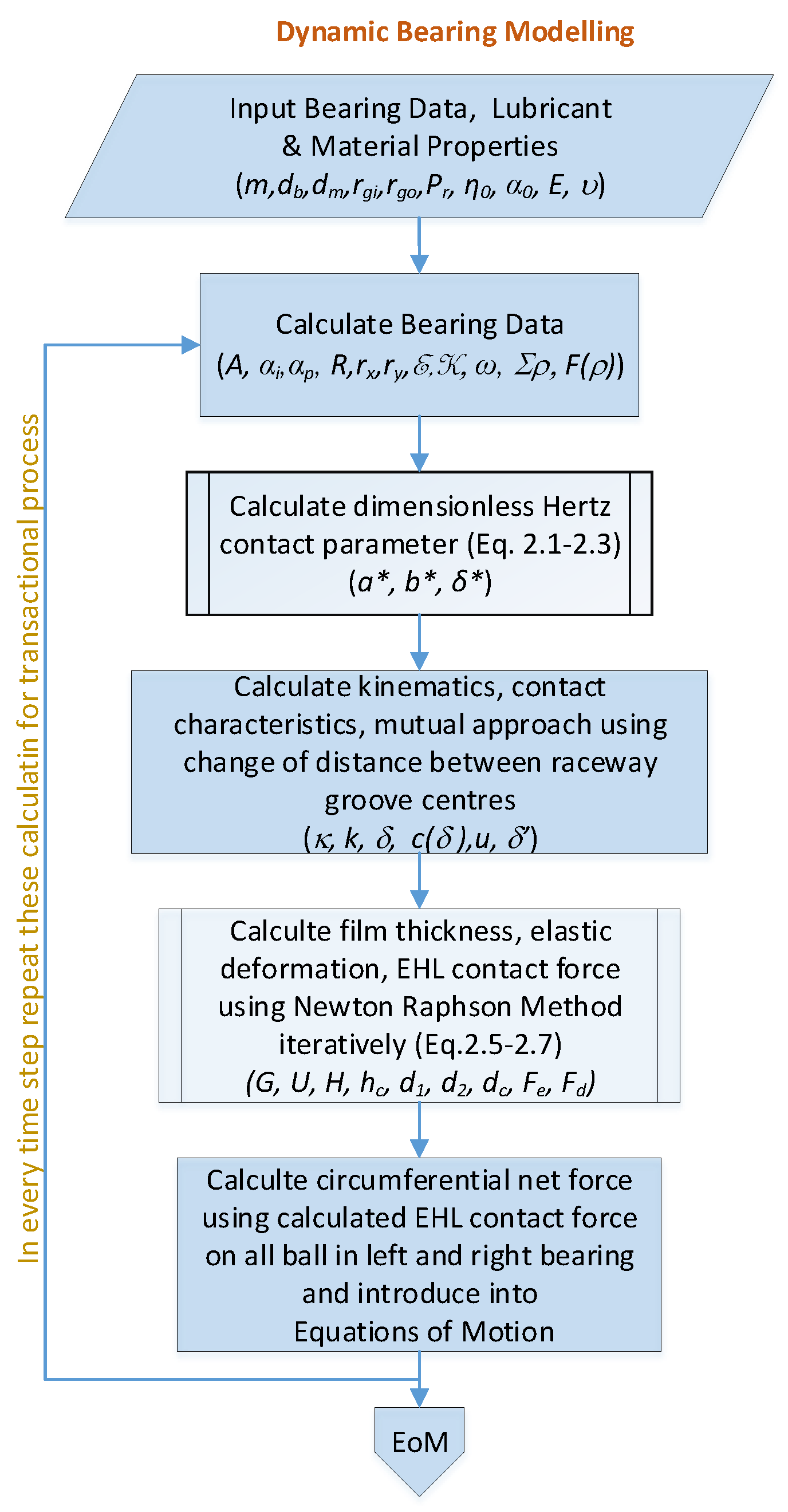
In order to determine the characteristics of bearing, a dynamic bearing model is established. The contact theory approach is based on and Hertz’s contact theory is used for modeling. The algorithm [27] is presented in Appendix A to the established dynamic bearing model. To calculate the load–deflection relationship, for the Hertz contact parameter, the relationship between the elliptic contact parameter with the curvature difference and the first and the second kind of elliptical integral is used. An approximate analytical solution of first and second kind elliptic integrals [54] is employed to calculate , , and k given in Equations (1)–(4).
For the contact characteristic, deformation and film thickness at each contact must be obtained [55]. Then, the resultant net force on the bearing can be calculated using the EHL contact force on each rolling element. To calculate dimensionless central film thickness equation (as a function of dimensionless load, dimensionless speed, dimensionless material property, and ellipticity ratio) Equation (5) [56] is used.
For the quasi-static case from Figure 1, elastic deformation (along the ball–ring contact angle direction) can be calculated as the sum of film thickness and mutual approach by Equation (6) [57].
Hereby, each contact in the bearing can be modelled as a Kelvin–Voigt element shown in Figure 2 and the contact force can be determined iteratively for a given mutual approach by the quasi-static method. For the mutual approach in Equation (6), the expression derived by Akturk [13] is used.
The EHL contact force can be calculated using the Newton–Raphson method quasi-statically by Equation (7). The solution method is given in detail by Bal [57]. For the main source of damping, the dissipative force represented in Equation (7), it is assumed that it is induced by the viscous losses in the lubricant. For the dissipative force, hysteretic damping [58] could be used as an alternative depending on the working conditions.
When a rolling element rotates between the inner and outer rings, it is continuously in contact with the rings at different points and contact geometry continuously changes. Hence contact deformation and film thickness also change continuously. Therefore at every timestep, these parameters should be re-calculated.
2.1.2. Rigid Rotor Supported by ACBB System
A spindle shaft is modelled as a rigid shaft bearing system supported by ACBB as shown in Figure 3. To determine the dynamic behaviour of the shaft-bearing system, it is necessary to obtain the time solution of the system for different operating conditions. The external forces and loads acting on the shaft bearing system and the coordinate system are also shown in Figure 3.
In modelling, the shaft-bearing system accepted as 5 DoF, fully flooded isothermal EHL conditions and Newtonian fluid behaviour are assumed. Simplified pure rolling (no-slip) contact theory is used for kinematic analyses. The shaft is assumed to rigid to eliminate its flexural natural modes (rigid body mode considered), and the damping consists of a lubricant effect.
The time-dependent angular position of ball is given Equation (8), therefore, equations of motion are given (Equation (9)).
The equation of motion is solved using the Runge–Kutta method to examine the dynamic behaviour of the shaft-bearing system and the time-dependent response is obtained. With the rotation of the shaft, the contact geometry, oil film thickness, and contact characteristics value of each ball change depending on the solution of the equations of motion.
2.2. Experimental Studies
An experimental setup presented in Figure 4 is designed and constructed to validate the theoretical results. Experimental data can be obtained for different preloads, shaft speeds, and operating conditions in which simulated in the theoretical model using this setup. In addition, different shaft weights, misalignment, rotated mounting of bearings, and bearing defects can also be tested.
FAG7206 X-life type angular contact ball bearings are used in the experimental setup. A three-phase electric motor and a PLC system to control inputs and outputs are also used. There is a frequency inverter for speed adjustment and an encoder to ensure the accuracy of the set shaft speed. The experimental setup contains a bolt and nut mechanism to give preload, S type load cell to measure the amount of preload, a precision jack to adjust the misalignment of the two bearings, a tightening bolt mechanism on the bearing ring to give a measurable diametrical error, a Cardan shaft to prevent pruning while preloading, and a bed system that can give misalignment. Concentric additional masses can be attached to the shaft for studied scenarios.
For rolling element bearing analysis, the idle side is used to acquire data, as there will be Cardan shaft and engine vibrations on the engine side.
3. Results and Discussion
3.1. Simulation Results
In order to examine the effect of preload, the shaft-bearing (geometrically flawless) system model is simulated in the range of 400 rpm to 5000 rpm in increments of 200 rpm for EHL condition. Shaft vibrations that occur at all DoF are given in Figure 5 in the time domain for a selected case. Bearing geometry and system data for computation can be found in Appendix B and Appendix C respectively and calculated bearing variable compliance frequencies are given in Appendix D.
3.1.1. Effect of Preload in Time Domain
Vibrations in the x-axis for different preloads are given in Figure 6. It can be seen that the vibration peak to peak amplitudes decrease with the increase in preload. This is because the preload increases rigidity and the clearance inside the bearing is not available. However, it should be noted that over preloading can cause an increase in stress on the bearing elements and adversely affect the material life and wear. The same situation exists in vibrations of in the other directions, but it is not given here for sake of brevity.
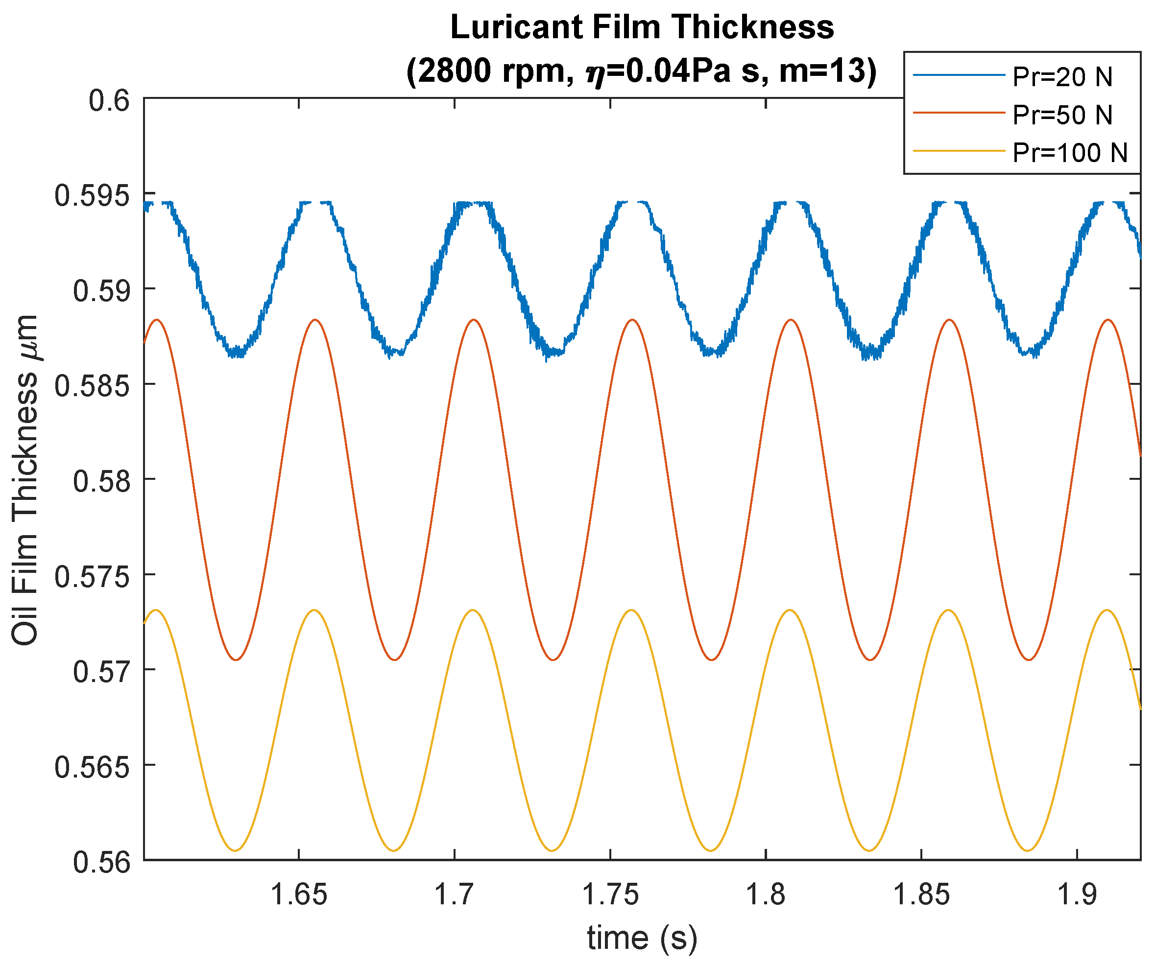
The film thickness decreases with preload as seen in Figure 7. Increasing the load increases the film pressure. Hence, increased preload leads to a decrease in the amount of oil entering the contact region, and further increasing the load can cause starved lubrication.
In this paper, EHL film thickness was calculated using the quasi-static approach iteratively using Equations (5)–(7). The film thickness, calculated by assuming that it converges to the steady-state at every timestep, however, has an actual oscillating around the magnitude of this calculated value. The effect of the preload on central film thickness and changes of thickness at the ball in the time domain is given in Figure 7.
Increasing preload is also increasing contact angle, as seen in Figure 8. This makes bigger thrust load and thrust vibrations. Additionally, the unloaded region will not be available with increasing preload.
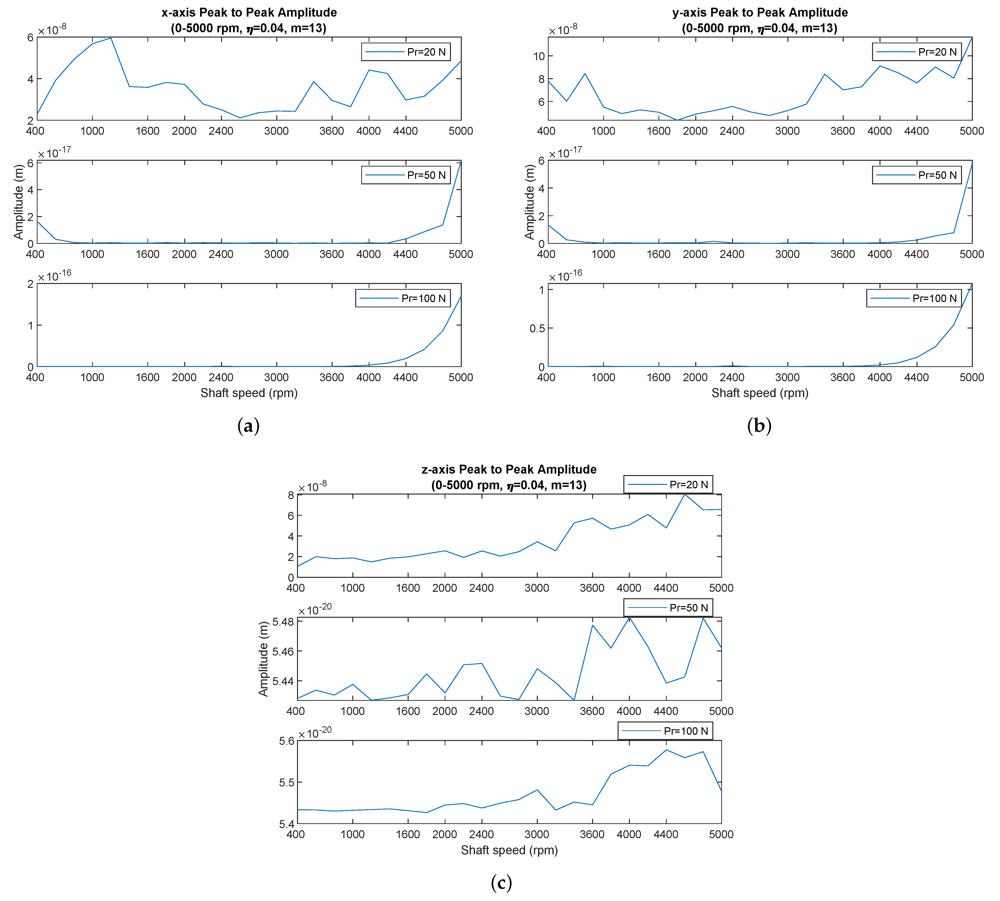
The effect of preloading can be observed in vibration peak to peak amplitudes in Figure 9 also. There is a decrease in the vibration amplitudes in the x and y axis when the preload is increased. This is because of an increase of the contact stiffness as it behaves as a hardening spring whose deformation depends on the preload. Hence, with larger preloads, the vibration amplitudes associated with the BPV will be reduced. This decrease is about 9 times when it is increased from 20 N to 50 N, while it is very small when it is increased from 50 N to 100 N. It is seen that the amplitudes have a similar change in the peak-to-peak z axis for 20 N to 50 N preload. This is due to the load shifting to the z axis with the increase in preload.
3.1.2. Effect of Preload in Frequency Domain
In order to examine the simulation results in the frequency domain, FFT transformation has been applied. The effect of preload can also be observed in the frequency spectrum. It is noteworthy that BPF level and its harmonics decrease with the increasing of preload, considering the vibrations in the x, y, and z axis in Figure 10. It is also seen that the vibration amplitudes in the x axis are greater as the shaft load is acting in the x axis direction.
It is observed that the natural frequency of the system is stimulated in the 1000 Hz band in the x and y axis spectra. The natural frequencies in the x and y directions are also different from each other since the anisotropic contact characteristic and the shaft weight acts in the x direction.
Vibrations at lower frequencies in the z-axis are another noticeable situation. It is observed that axial vibration bandwidth is increased two times with the preload increased to 200 N. However, vibrations in the z-axis exhibit a more complex behaviour with increasing preload.
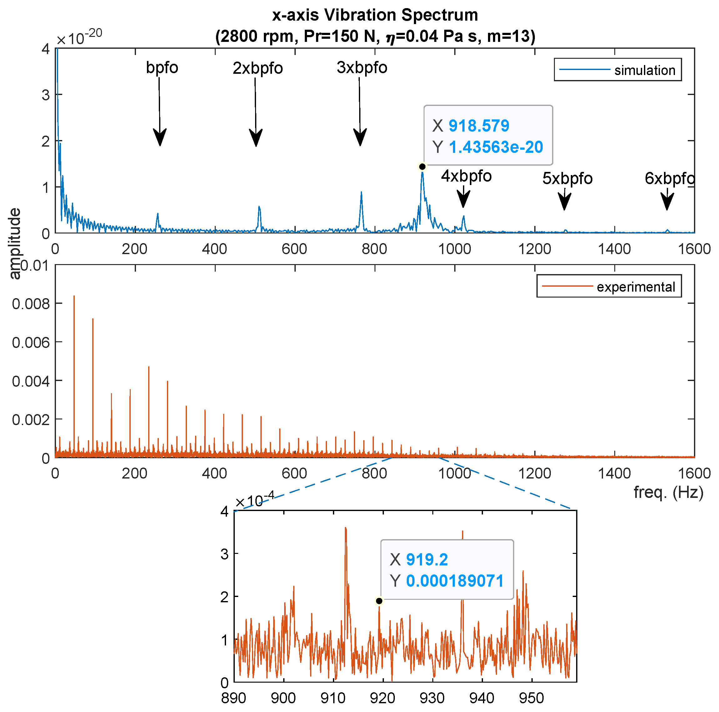
On the other hand, as can be seen from the analytical approach given in Appendix E, the natural frequency increases with preload, in other words, the natural frequency shifts towards higher values. This shifting can be seen in Figure 10. When preload changed from 50 N to 150 N, the natural frequency in x direction is shifted from 833.1 Hz to 918.5 Hz and the natural frequency in y direction is shifted from 830.1 Hz to 915 Hz. Shifting of system natural frequencies will carry the risk of resonating with BFP and its sub-harmonics at higher frequencies.
3.2. Experimental Results
In the experimental study, accelerometers were attached both in the vertical (x-axis) and in the horizontal (y-axis) directions to the bearing housing on the idler side of the experimental setup, and data were collected for 5 s after the steady-state condition is reached. The sampling frequency of the accelerometers is 25,600 Hz. With the experimental setup, data were acquired from 400 rpm to 3000 rpm shaft speed with 200 rpm steps for each case.
In the experimental part of the study, a total of 14 different shaft speeds were performed for each scenario, and spectrum analysis was performed after the envelope analysis. For more detailed information and cases may be found in [36].
Effect of Preload
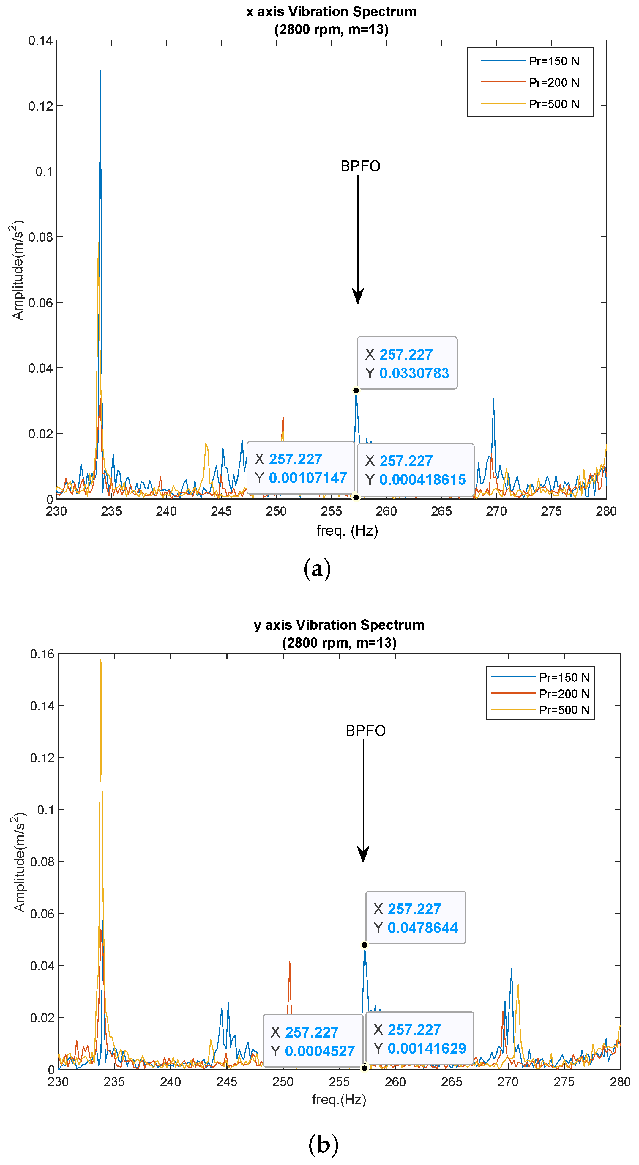
Vibrations data on x-axis acquired from the experimental setup are presented in Figure 11 for the selected speeds. It is observed that there is a decrease in the peak-to-peak vibration amplitudes in parallel with the results obtained in the theoretical study. However, this decrease is less noticeable when the preload is increased from 200 N to 500 N. This is because the 500 N preload is higher than the bearing catalogue value, and the increased deformation in the rolling element leads to the hardening-spring characteristic, thus increasing the contact stiffness.
It is considered that vibrations in the y-axis of Figure 12, similar to the x-axis, there is a decrease in the peak-to-peak vibration amplitudes with the increase in preload, and the amount of decrease is a little less for a preload increased to 500 N.
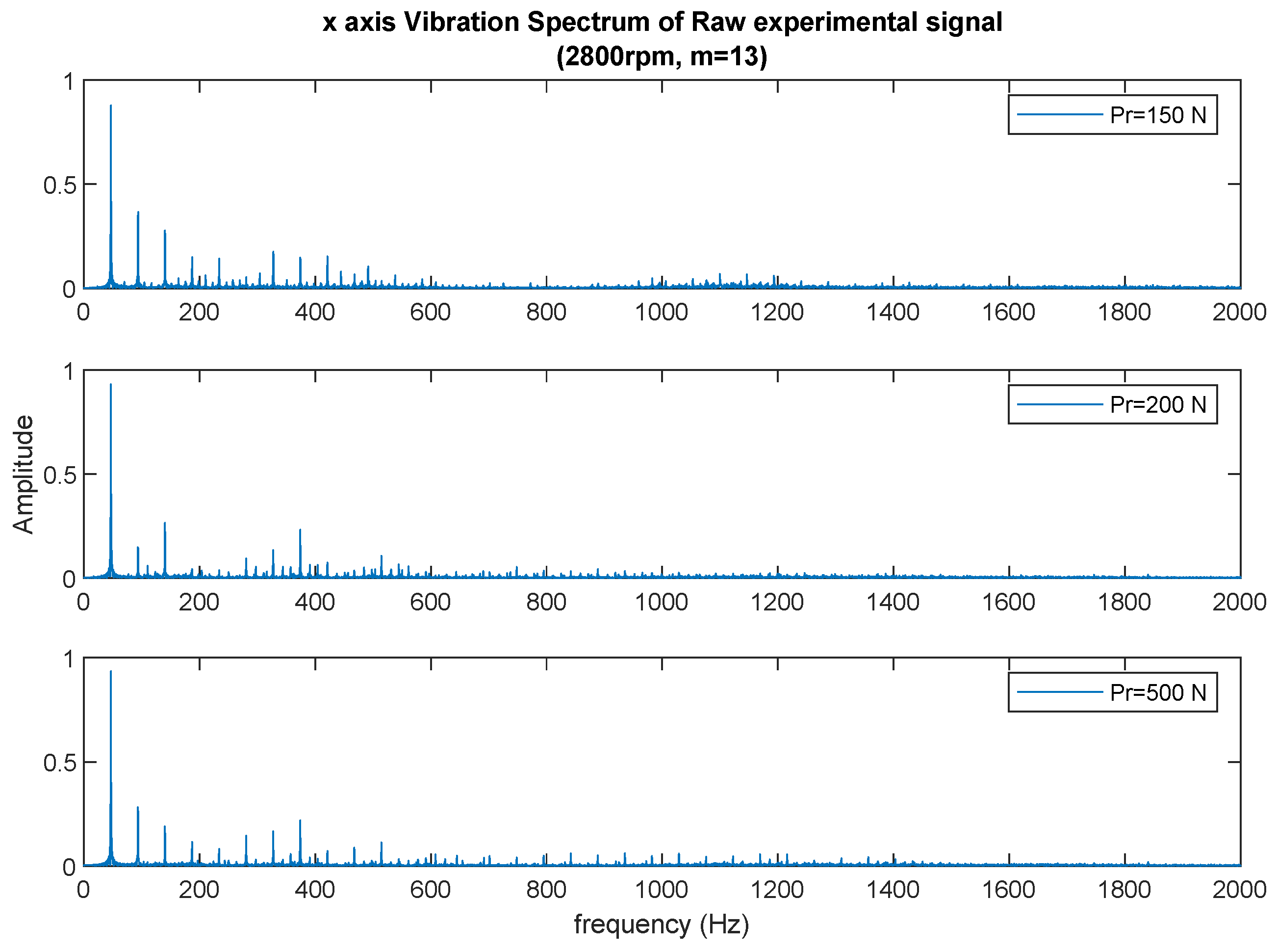
For more details, the values in the frequency spectrum should be scrutinized. In Figure 13, the waterfall diagrams of vibrations in the x-axis are presented for different preloads. Vibration amplitudes increase with increasing shaft speeds and high amplitudes are not seen at low shaft speeds both in the x-axis and in the y-axis direction. The reason for the increase in amplitudes with the increase of shaft speeds is that the experimental setup contains some inevitable untoward anomalies that are resonated by shaft speed excitation, such as misalignment. Generally, the amplitudes in the x-axis direction are greater than the amplitudes in the y-axis direction due to the weight of the shaft acting in the x direction. This situation was also encountered in theoretical study.
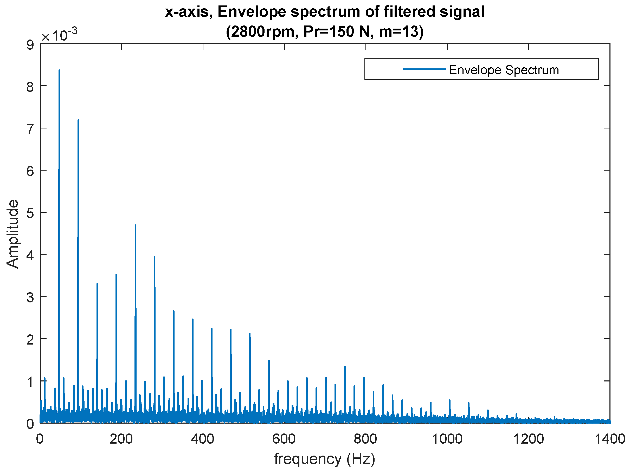
Vibration peaks at shaft speed and its harmonics are clearly dominant in the spectrum of raw experimental data for 2800 rpm shaft speed in Figure 14. An envelope analysis was performed on the experimental data in order to see the effect of preload and the results are given in Figure 15.
Digital signal processing (DSP) methods are widely used to examine cyclostationary signals seen in rotating and reciprocating machines. Preprocessing (remove speed fluctuation/order tracking), kurtogram (determining optimum band for filtering and demodulation), filtering, and envelope analysis methods were used to examine bearing frequencies in experimental data.
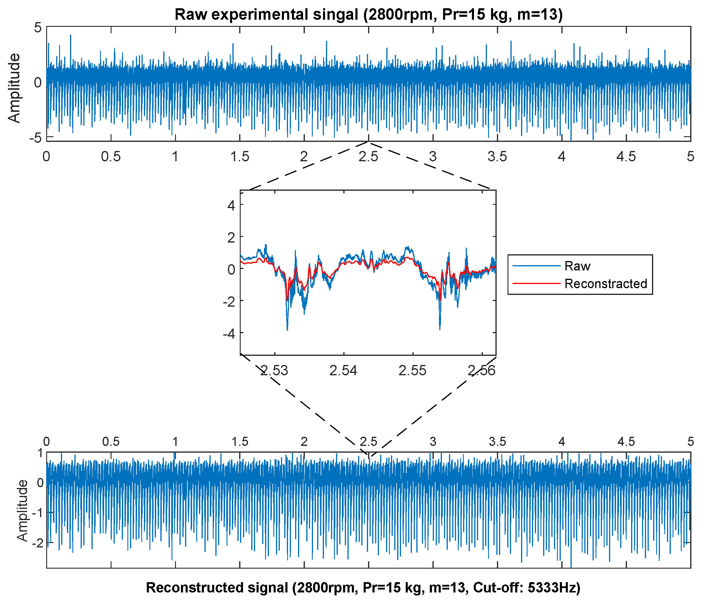
Since there are also noise and non-repeating amplitudes in the experimental signal and the high-frequency region does not contain the data of interest, a band-pass filter is applied to the experimental data, and then envelope analysis is performed.
Even though the unit of the acceleration data is changed as a result of the envelope analysis, since the signal will be obtained physically showing the same properties as the raw signal, the frequency spectrum of the obtained signal will coincide with the real situation for examination and interpretation. In the light of the information obtained in the theoretical study, the signal for the 5 kHz cut-off frequency was regenerated using inverse FFT since there were no interesting data at high frequencies. Afterwards, 25 Hz 1.6 kHz band-pass filtering was applied, and the optimum bandwidth and time window for demodulation with envelope analysis were determined by kurtogram. Bearing frequencies were examined in the envelope spectrum from the obtained results. Figure 15 shows the regenerated signal using the inverse FFT for the raw data and the 5 kHz cut-off frequency. Thus, the signal is free from high-frequency components and noise.
The signal obtained from the experimental data with DSP and the kurtosis of the raw signal is given in Figure 16. After DSP, kurtosis increased from 4.5775 to 18.519 (4 times). In the envelope spectrum, the shaft frequency and harmonics in the filtered band are also obvious.
However, BPF and its harmonics are seen in the x-axis envelope spectrum in Figure 17. The appearance of amplitudes on BPF and its harmonics is an expected situation and this was also encountered in theoretical study. Similarly, the ball passage vibrations can be seen in the y-axis frequency spectrum in Figure 18.
In order to understand the effect of preloading, the x-axis spectrum of the raw data is given together for different preload values in Figure 19. In the raw data of shaft vibrations, small differences in the amplitudes of the shaft frequency and its harmonics are noticeable for various preloads. This situation can be the imperfection of the experimental setup or due to the relatively high preload values. This may lead to the conclusion that excessive preloading after an optimum preload value will not provide benefits in terms of vibration severity.
However, when looking at the spectrum of the raw experimental data in Figure 19, it is observed that the vibration amplitudes on the ball passage vibrations decrease 10 times when the preload is increased from 150 N to 200 N, while the vibration amplitudes are still in the same order when it is increased from 200 N to 500 N. This result indicates that excessive preload does not provide expected benefit. We should also take into account the unit change of the acceleration data in the obtained signal by envelope analysis; it will change the amplitudes even though it does not physically affect the frequency spectrum.
3.3. Comparison
In order to determine the effect of preload, the theoretical and experimental data were investigated simultaneously. The peaks at BPF and its harmonics are observed in both the theoretical and experimental x-axis spectrum in Figure 20. However, the peak at the natural frequency of the system at 918.6 Hz, which is apparently seen in the theoretical results, stands out at 919.2 Hz in experimental data.
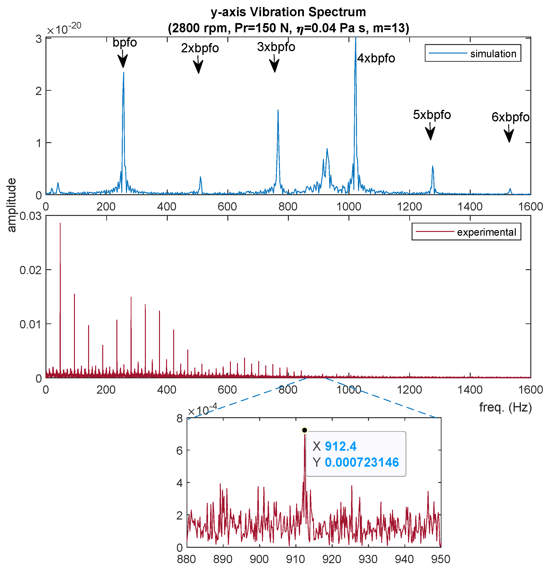
In both the theoretical and experimental y-axis spectrum in Figure 21, the BPF and its first six harmonics are present in the theoretical results. The natural frequency of the shaft is seen at 913 Hz.
Natural frequencies in the x and y axis are different. In addition, after envelope analysis in experimental data, shaft frequency and harmonics are still dominant. From the results its seen that the theoretical model corresponds with the experimental setup.
4. Conclusions
In this paper, vibrations of the shaft-bearing system which are supported by elastohydrodynamic lubricated ball bearings are investigated theoretically and experimentally.
In order to perform dynamic bearing modelling, elastic and hydrodynamic effects are defined and a contact model is established using the relationship between them. Especially the spindle is modelled with 5 DoF and vibration behaviour is analyzed. In order to investigate the vibration behaviour of the system, the equations of motion for EHL condition are solved for different preload and shaft speeds, and the variable compliance frequencies of the bearings and the natural frequencies of the system are determined. For this, EHL theory, simplified rolling contact theory, and system dynamics theory were used. Both the time and the frequency response of the system are presented.
In the experimental setup, 3 DoF (1 horizontal y-axis and 2 vertical x-axis (one of them servo coupled side the other idle side of the shaft)) measurements are fulfilled. The data acquired from the idle side is used for envelope and spectral analysis.
Results obtained from the theoretical model and the experimental setup have been compared. The relationship between preload and vibration behaviour of shaft bearing system is presented for different speeds. Similar results are obtained from both of the theoretical model and experimental setup, for investigating the effect of preload on the vibration behaviour. Therefore, the EHL contact dynamic bearing model presented in the study can be used with a reasonable accuracy to examine effect of preload on the shaft-bearing system. Additionally, using spectral analysis together with time-domain signal processing technics has given better results for obtaining variable compliance frequencies of bearing. The considered conclusions are given as follows:
- Vibration amplitudes and BPV peak-to-peak amplitudes are decreased by increasing preload. This attenuation on the amplitute of BPV is reached to 10 times. However, at the same time, the natural frequency of system is shifted a higher value. This shifting is apparently seen in the results of both proposed theoretical model and experimental study.
- It is observed that increased preload has reduced the visibility of the bearing variable compliance frequencies and harmonics in the frequency spectrum.
- Axial vibration bandwidth is increased approximately two times with increased preload. However, vibrations in the z-axis exhibit a more complex behaviour with increasing preload. An increase in the contact angle with preload can cause an increase in the axial mode vibrations.
- Using signal processing with envelope spectrum gives better results in obtaining of bearing variable compliance frequencies. Kurtosis is increased four times by using a signal processing technique.
Author Contributions
H.B. and K.A.: conceptualization of this study, methodology, software, data curation, writing—original draft preparation. T.K. and N.A.: coordinating and supervising. All authors have read and agreed to the published version of the manuscript.
Funding
This research received no external funding.
Data Availability Statement
The result data presented in this study are available in figures and tables.
Conflicts of Interest
The authors declare no conflict of interest.
Nomenclature
| Dimensionless semimajor and semiminor axis of contact ellipse | |
| A | Distance between raceway grove center, m |
| c | Viscous damping factor, Ns/m |
| Elastic contact deformations, m | |
| Elastic contact deformations at contact centre, m | |
| Ball diameter, m; pitch diameter, m | |
| Modulus of elasticity, reduced module of elastacity, N/m2 | |
| Frequency, ball passage frequency, Hz | |
| Normal EHL contact force; dissipative force; elastic restoring force; Hertz normal force, N | |
| G | Dimensionless materials parameter, |
| Film thickness m; central film thickness, m | |
| H | Dimensionless film thickness, |
| k | Stiffness factor, N/m |
| m | Number of balls, kg |
| n | Rotational speed of the spindle, rpm |
| M | Mass of shaft, kg |
| p | Pressure, Pa |
| Preload, N | |
| Radii of curvature, m | |
| R | Curvature sum, ball centre focus radius under zero load, m |
| Q | External forces, N |
| u | Surface velocity in direction of motion , m/s |
| U | Dimensionless speed parameter, |
| t | Time, s |
| W | Dimensionless load parameter, |
| Coordinate axis, m | |
| Pressure-viscosity coefficient, Pa | |
| Instantaneous contact angle; unloaded contact angle; | |
| preloaded contact angle, rad | |
| Mutual approach between contacting bodies m | |
| Complete elliptic integral of the second kind | |
| Ellipticity parameter, a/b | |
| Complete elliptic integral of the first kind | |
| Viscosity, Pa s | |
| Curvature, | |
| , | Angular velocity, cage angular velocity, rad/s |
| The angle between the fixed and moving reference axis, rad/s | |
| Rock angle of the shaft about x axis, rad | |
| Rock angle of the shaft about y axis, rad | |
| Abbreviations | |
| ACBB | Angular Contact Ball Bearing |
| EHL | Elasto Hydrodynmic Lubrication |
| BPF | Ball Pass Frequency |
| BPV | Ball Passage Vibrations |
| BSF | Ball Spin Frequency |
| DSP | Digital Signal Procecessing |
| PLC | Programmable Logic Controller |
Appendix A. Bearing Modelling
The bearing modelling algorithm can be seen in Figure A1.
Figure A1.
ACBB modelling algorithm.

Appendix B. Bearing Geometry
The angular contact ball bearing dimensions and parameters can be seen in Figure A2.
Figure A2.
Angular contact ball bearing geometry.

Appendix C. System Data for Numerical Computation
Rigid shaft bearing system data used in simulation and the experimental setup are given in Table A1 and Table A2.

Table A1.
Shaft and bearing data for simulation and experimental setup.
| Description | Dimension |
|---|---|
| Type | Angular Contact Ball Bearing |
| Outer Raceway Diameter | m |
| Outer Ring Diameter | m |
| Inner Ring Diameter | m |
| Inner Raceway Diameter | m |
| Pitch Diameter | m |
| Inner Ring Groove Radius | m |
| Outer Ring Groove Radius | m |
| Bearing Width | m |
| Ball Diameter | m |
| Number of Balls | |
| Unloaded Contact Angle | m |
| Young Module | GPa |
| Poisson Ratio | |
| Type | Rigid Shaft |
| Diameter | m |
| Length | m |
| Mass | kg |
| Lenght between Bearings | m |
| Lenght CG to Bearing | , m m |
| Lubricant Properties | Pas, Pa |
Table A2.
Sensor data.
| Measurement Place | Accelometer No | Sensivity (mv/ms2) | Sensivity (mv/g) |
|---|---|---|---|
| Idle side Horz. y-axis | AI8 1438 | 0.818 | 8.02 |
| Idle side Vert. x-axis | AI1 1439 | 0.797 | 7.83 |
| Motor side Vert. x-axis | AI9 1437 | 0.797 | 7.82 |
Appendix D. Variable Compliance Frequancies of Bearing
FAG 7206—angular contact ball bearing variable compliance frequencies are found in Table A1. They can be calculated using Equations (A1)–(A3).
Table A3.
Bearing frequencies.
| Speed (rpm) | Cage Freq. (Hz) | BSF (Hz) | BPFO (Hz) | BPFI (Hz) |
|---|---|---|---|---|
| 200 | 1.4023 | 7.843984 | 18.229699 | 25.1036 |
| 400 | 2.8046 | 15.687969 | 36.459398 | 50.2073 |
| 600 | 4.2069 | 23.531953 | 54.689097 | 75.3109 |
| 800 | 5.6091 | 31.375938 | 72.918795 | 100.4145 |
| 1000 | 7.0114 | 39.219922 | 91.148494 | 125.5182 |
| 1200 | 8.4137 | 47.063907 | 109.378193 | 150.6218 |
| 1400 | 9.8160 | 54.907891 | 127.607892 | 175.7254 |
| 1600 | 11.2183 | 62.751876 | 145.837591 | 200.8291 |
| 1800 | 12.6206 | 70.595860 | 164.067290 | 225.9327 |
| 2000 | 14.0228 | 78.439845 | 182.296989 | 251.0363 |
| 2200 | 15.4251 | 86.283829 | 200.526687 | 276.1400 |
| 2400 | 16.8274 | 94.127814 | 218.756386 | 301.2436 |
| 2600 | 18.2297 | 101.971798 | 236.986085 | 326.3472 |
| 2800 | 19.6320 | 109.815783 | 255.215784 | 351.4509 |
| 3000 | 21.0343 | 117.659767 | 273.445483 | 376.5545 |
Appendix E. Effect of Preload on the Natural Frequency
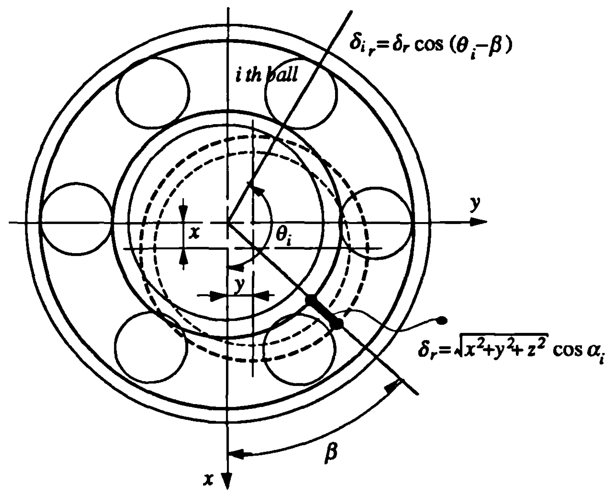
Akturk [13] shows that the maximum deflection will be caused at the angle due to the displacement of the inner ring centre in the direction for an angular contact ball bearing in Figure A3. This deflection is given by Equation (A4) and angle can be calculated with Equation (A4).
Figure A3.
The force on the ith ball due to the shaft centre deflection [13].
Figure A3.
The force on the ith ball due to the shaft centre deflection [13].

If the total forces in the directions are calculated:
where m is the number of balls and .
From these forces the stiffness coefficients in the directions can be derived. For brevity here only x direction will be derived. The force in the x direction can be written as Equation (A10).
where,
As Equation (A10) suggests, for a given time , S is constant. Therefore the derivation of Equation (A10) with respect to the deflection will give an instantaneous linear stiffness around a value of as:
The approximate natural frequency of the system in the x direction, around the deflection will be Equation (A13):
If the deflection is considered in terms of a constant deflection and a small variation around , Equation (A13) will take the form of:
References
- Wardle, F.P. Vibration forces produced by waviness of the rolling surfaces of thrust loaded ball bearings Part 1: Theory. Proc. Inst. Mech. Eng. Part J. Mech. Eng. Sci. 1988, 202, 305–312. [Google Scholar] [CrossRef]
- Wardle, F.P. Vibration forces produced by waviness of the rolling surfaces of thrust loaded ball bearings Part 2: Experimental Validation. Proc. Inst. Mech. Eng. Part J. Mech. Eng. Sci. 1988, 202, 313–319. [Google Scholar] [CrossRef]
- Rahnejat, H.; Gohar, R. The Vibrations of Radial Ball Bearings. Proc. Inst. Mech. Eng. Part J. Mech. Eng. Sci. 1985, 199, 181–193. [Google Scholar] [CrossRef] [Green Version]
- Mostofi, A. Oil Film thickness and Pressure Distribution in Elastohydrodynamic Elliptical Contacts. Ph.D. Thesis, Department of Mechanical Engineering Imperial College of Science and Technology Unıversity of London, London, UK, 1981. [Google Scholar]
- Johns-Rahnejat, P.M.; Gohar, R. Measuring contact pressure distributions under elastohydrodynamic point contacts. Tribotest 1994, 1, 33–53. [Google Scholar] [CrossRef]
- Aini, R.; Rahnejat, H.; Gohar, R. Vibration Modeling of Rotating Spindles Supported by Lubricated Bearings. J. Tribol. 2000, 124, 158–165. [Google Scholar] [CrossRef]
- Aktürk, N.; Gohar, R. Damping the Vibrations of a Rigid Shaft Supported by Ball Bearings by Means of External Elastomeric O-ring Dampers. Proc. Inst. Mech. Eng. Part J. Eng. Tribol. 1994, 208, 183–190. [Google Scholar] [CrossRef]
- Aini, R.; Rahnejat, H.; Gohar, R. A five degrees of freedom analysis of vibrations in precision spindles. Int. J. Mach. Tools Manuf. 1990, 30, 1–18. [Google Scholar] [CrossRef]
- Aktürk, N.; Uneeb, M.; Gohar, R. The Effects of Number of Balls and Preload on Vibrations Associated With Ball Bearings. J. Tribol. 1997, 119, 747–753. [Google Scholar] [CrossRef]
- Jalali, D.V.; Rahnejat, H.; Gohar, R.; Jin, Z.M. Prediction of oil-film thickness and shape in elliptical point contacts under combined rolling and sliding motion. Proc. Inst. Mech. Eng. Part J. Eng. Tribol. 2000, 214, 427–437. [Google Scholar] [CrossRef] [Green Version]
- Vahid, D.J.; Rahnejat, H.; Jin, Z.M.; Downson, D. Transient analysis of isothermal elastohydrodynamic circular point contacts. Proc. Inst. Mech. Eng. Part J. Mech. Eng. Sci. 2001, 215, 1159–1172. [Google Scholar] [CrossRef] [Green Version]
- Karaçay, T.; Aktürk, N. Vibrations of a grinding spindle supported by angular contact ball bearings. Proc. Inst. Mech. Eng. Part J. Multi-Body Dyn. 2008, 222, 61–75. [Google Scholar] [CrossRef]
- Aktürk, N. Dynamics of a Rigid Shaft Supported by Angular Contact Ball Bearings. Ph.D. Thesis, Department of Mechanical Engineering Imperial College of Science and Technology Unıversity of London, London, UK, 1993. [Google Scholar]
- Karacay, T.; Akturk, N. Experimental diagnostics of ball bearings using statistical and spectral methods. Tribol. Int. 2009, 42, 836–843. [Google Scholar] [CrossRef]
- Wijnant, Y.H.; Wensing, J.A.; Nijen, G.C. The influence of lubrication on the dynamic behaviour of ball bearings. J. Sound Vib. 1999, 222, 579–596. [Google Scholar] [CrossRef]
- Zhang, Y.Y.; Wang, X.L.; Yan, X.L. Dynamic Behaviors of the Elastohydrodynamic Lubricated Contact for Rolling Bearings. J. Tribol. 2012, 135, 021501. [Google Scholar] [CrossRef]
- Wijnant, Y.H. Contact Dynamics in the Field of Elastohydrodynamic Lubrication. Ph.D. Thesis, University of Twente, Enschede, The Netherlands, 1998. [Google Scholar]
- Mohammadpour, M.; Johns-Rahnejat, P.; Rahnejat, H. Roller bearing dynamics under transient thermal-mixed non-Newtonian elastohydrodynamic regime of lubrication. Proc. Inst. Mech. Eng. Part J. Multi-Body Dyn. 2015, 229, 407–423. [Google Scholar] [CrossRef] [Green Version]
- Alfares, M.; Saleem, O.; Majeed, M. Analytical study of thermal variation impact on dynamics of a spindle bearing system. Proc. Inst. Mech. Eng. Part J. Multi-Body Dyn. 2019, 233, 871–898. [Google Scholar] [CrossRef]
- Harsha, S.P.; Sandeep, K.; Prakash, R. Effects of Preload and Number of Balls on Nonlinear Dynamic Behavior of Ball Bearing System. Int. J. Nonlinear Sci. Numer. Simul. 2003, 4, 265–278. [Google Scholar] [CrossRef]
- Bai, C.; Zhang, H.; Xu, Q. Effects of axial preload of ball bearing on the nonlinear dynamic characteristics of a rotor-bearing system. Nonlinear Dyn. 2008, 53, 173–190. [Google Scholar] [CrossRef]
- Zhang, X.; Han, Q.; Peng, Z.; Chu, F. A new nonlinear dynamic model of the rotor-bearing system considering preload and varying contact angle of the bearing. Commun. Nonlinear Sci. Numer. Simul. 2015, 22, 821–841. [Google Scholar] [CrossRef]
- Sopanen, J.; Mikkola, A. Dynamic model of a deep-groove ball bearing including localized and distributed defects. Part 1: Theory. Proc. Inst. Mech. Eng. Part J. Multi-Body Dyn. 2003, 217, 201–211. [Google Scholar] [CrossRef]
- Sopanen, J.; Mikkola, A. Dynamic model of a deep-groove ball bearing including localized and distributed defects. Part 2: Implementation and results. Proc. Inst. Mech. Eng. Part J. Multi-Body Dyn. 2003, 217, 213–223. [Google Scholar] [CrossRef]
- Aktürk, N. The Effect of Waviness on Vibrations Associated with Ball Bearings. J. Tribol. 1999, 121, 667–677. [Google Scholar] [CrossRef]
- Karaçay, T. Açısal Temaslı Rulmanlarla Yataklanmış Şaftların Dinamiği ve Rulman Hatalarının Deneysel Analizi (Experimental Analysis of a Dynamics of a Shaft Supported by Defective Angular Contact Ball Bearings). Ph.D. Thesis, The Department of Mechanical Engineering, Faculty of Engineering, Gazi University, Ankara, Turkey, 2006. [Google Scholar]
- Bal, H. Rüzgâr Türbinlerinde Kullanılan ElastoHidrodinamik Yağlamalı Rulmanların Dinamik Davranışının İncelenmesi, (Investigation of Dynamic Behaviour of Elasto-Hydrodynamic Lubricated Rolling Bearing Using in Wind Turbines). Ph.D. Thesis, The Department of Mechanical Engineering, Faculty of Engineering, Gazi University, Ankara, Turkey, 2018. [Google Scholar]
- Barthel, K. The shock pulse method for determining the condition of anti-friction bearings. In Proceedings of the Machinery Vibration Monitoring Analysis Seminar, Sponsored by the Vibration Institute, February 1978. [Google Scholar]
- De Azevedo, H.D.M.; Araújo, A.M.; Bouchonneau, N. A review of wind turbine bearing condition monitoring: State of the art and challenges. Renew. Sustain. Energy Rev. 2016, 56, 368–379. [Google Scholar] [CrossRef]
- Tallian, T.E.; Gustafsson, O.G. Progress in rolling bearing vibration research and control. ASLE Trans. 1965, 8, 195–207. [Google Scholar] [CrossRef]
- Miyachi, T.; Seki, K. An Investigation of Early Detection of Defects in Ball Bearings by Vibration Monitoring (3rd Report, Detection Limit of Flaking). Tech. Rep. Natl. Aerosp. Lab. 1986. [Google Scholar] [CrossRef]
- Randall, R.B.; Antoni, J.; Chobsaard, S. The relationship between spectral correlation and envelope analysis in the diagnostics of bearing faults and other cyclostationary machine signals. Mech. Syst. Signal Process. 2001, 15, 945–962. [Google Scholar] [CrossRef]
- Khanam, S.; Tandon, N.; Dutt, J. Fault size estimation in the outer race of ball bearing using discrete wavelet transform of the vibration signal. Procedia Technol. 2014, 14, 12–19. [Google Scholar] [CrossRef] [Green Version]
- Prashad, H. The effect of cage and roller slip on the measured defect frequency response of rolling-element bearings. ASLE Trans. 1987, 30, 360–367. [Google Scholar] [CrossRef]
- Dybała, J. Diagnosing of rolling-element bearings using amplitude level-based decomposition of machine vibration signal. Measurement 2018, 126, 143–155. [Google Scholar] [CrossRef]
- Ateş, K. Açısal Temaslı Rulmanlarda Montaj Hatalarının Titreşimlere Etkisinin Teorik ve Deneysel İncelenmesi (Theorical And Experimental Investigaton of Angular Contact Ball Bearing Vibrations with Mounting Errors). Ph.D. Thesis, The Department of Mechanical Engineering, Faculty of Engineering, Gazi University, Ankara, Turkey, 2019. [Google Scholar]
- Walford, T.; Stone, B. The measurement of the radial stiffness of rolling element bearings under oscillating conditions. J. Mech. Eng. Sci. 1980, 22, 175–181. [Google Scholar] [CrossRef]
- Ocak, H.; Loparo, K.A. Estimation of the running speed and bearing defect frequencies of an induction motor from vibration data. Mech. Syst. Signal Process. 2004, 18, 515–533. [Google Scholar] [CrossRef]
- Li, Y.; Zhang, C.; Kurfess, T.; Danyluk, S.; Liang, S. Diagnostics and prognostics of a single surface defect on roller bearings. Proc. Inst. Mech. Eng. Part J. Mech. Eng. Sci. 2000, 214, 1173–1185. [Google Scholar] [CrossRef]
- Kim, P.Y. A review of rolling element bearing health monitoring. III—Preliminary test results on eddy current proximity transducer technique. In Proceedings of the International Conference on Vibrations in Rotating Machinery, Heslington, UK, 11–13 September 1984; pp. 119–125. [Google Scholar]
- Choudhury, A.; Tandon, N. Application of acoustic emission technique for the detection of defects in rolling element bearings. Tribol. Int. 2000, 33, 39–45. [Google Scholar] [CrossRef]
- Singh, G. Experimental investigations on induction machine condition monitoring and fault diagnosis using digital signal processing techniques. Electr. Power Syst. Res. 2003, 65, 197–221. [Google Scholar]
- Ericsson, S.; Grip, N.; Johansson, E.; Persson, L.E.; Sjöberg, R.; Strömberg, J.O. Towards automatic detection of local bearing defects in rotating machines. Mech. Syst. Signal Process. 2005, 19, 509–535. [Google Scholar] [CrossRef] [Green Version]
- Aktürk, N.; Uneeb, M. Application of vibration monitoring to rotating machinery. Gazi Üniv. Fen Bilim. Enstitüsü Derg. 1997, 10, 419–433. [Google Scholar]
- Al-Najjar, B. Accuracy, effectiveness and improvement of vibration-based maintenance in paper mills: Case studies. J. Sound Vib. 2000, 229, 389–410. [Google Scholar] [CrossRef]
- Orhan, S.; Aktürk, N.; Çelik, V. Vibration monitoring for defect diagnosis of rolling element bearings as a predictive maintenance tool: Comprehensive case studies. NDT E Int. 2006, 39, 293–298. [Google Scholar] [CrossRef]
- Prabhu, R. Rolling bearing diagnostics. In Proceedings of the Indo-US Symposium on Emerging Trends in Vibration and Noise Engineering, New Delhi, India, 18–20 March 1996; pp. 311–320. [Google Scholar]
- Devendiran, S.; Manivannan, K. Vibration based condition monitoring and fault diagnosis technologies for bearing and gear components—A review. Int. J. Appl. Eng. Res. 2016, 11, 3966–3975. [Google Scholar]
- Tse, P.W.; Peng, Y.; Yam, R. Wavelet analysis and envelope detection for rolling element bearing fault diagnosis—Their effectiveness and flexibilities. J. Vib. Acoust. 2001, 123, 303–310. [Google Scholar] [CrossRef]
- Mendel, E.; Rauber, T.W.; Varejão, F.M.; Batista, R.J. Rolling element bearing fault diagnosis in rotating machines of oil extraction rigs. In Proceedings of the 2009 17th European Signal Processing Conference, Glasgow, UK, 24–28 August 2009; pp. 1602–1606. [Google Scholar]
- Lacey, S.J. An overview of bearing vibration analysis. Maint. Asset Manag. 2008, 23, 32–42. [Google Scholar]
- Xu, M.; Feng, G.; He, Q.; Gu, F.; Ball, A. Vibration Characteristics of Rolling Element Bearings with Different Radial Clearances for Condition Monitoring of Wind Turbine. Appl. Sci. 2020, 10, 4731. [Google Scholar] [CrossRef]
- Ruan, D.; Chen, Y.; Gühmann, C.; Yan, J.; Li, Z. Dynamics Modeling of Bearing with Defect in Modelica and Application in Direct Transfer Learning from Simulation to Test Bench for Bearing Fault Diagnosis. Electronics 2022, 11, 622. [Google Scholar] [CrossRef]
- Antoine, J.F.; Visa, C.; Sauvey, C.; Abba, G. Approximate Analytical Model for Hertzian Elliptical Contact Problems. J. Tribol. 2006, 128, 660–664. [Google Scholar] [CrossRef]
- Gohar, R. Elastohydrodynamic, 2nd ed.; CRC Press: London, UK, 2001. [Google Scholar]
- Downson, D.; Hamrock, B. Ball Bearing Lubrication: The Elastohydrodynamics of Elliptical Contacts, 1st ed.; A Wiley-Interscience Publication: New York, NY, USA, 1981. [Google Scholar]
- Bal, H.; Aktürk, N. Vibration modeling of wind turbine shaft as rigid shaft supported by EHL contact ball bearings with overhung disc system. Tribol. Int. 2020, 151, 106481. [Google Scholar] [CrossRef]
- Hunt, K.H.; Crossley, F.R.E. Coefficient of Restitution Interpreted as Damping in Vibroimpact. J. Appl. Mech. 1975, 42, 440–445. [Google Scholar] [CrossRef]
Figure 1.
Elastic deformation due to squeezing motion and oil film thickness.

Figure 2.
Dynamic bearing model.

Figure 3.
Shaft-bearing system.

Figure 4.
Experimental setup.

Figure 5.
Shaft vibrations.

Figure 6.
The x-axis vibration for different preload.

Figure 7.
Oil film thickness variation with preload.

Figure 8.
Effect of the different preload to contact angle variation.

Figure 9.
Effect of the different preload to peak-to-peak amplitudes in (a) x axis, (b) y axis, (c) z axis.
Figure 9.
Effect of the different preload to peak-to-peak amplitudes in (a) x axis, (b) y axis, (c) z axis.

Figure 10.
Effect of the different preloads on the vibration spectrum (theoretical) in (a) x axis, (b) y axis, (c) z axis.
Figure 10.
Effect of the different preloads on the vibration spectrum (theoretical) in (a) x axis, (b) y axis, (c) z axis.

Figure 11.
Effect of preload on vibrations along the x-axis.

Figure 12.
Effect of preload on vibration along the y-axis.

Figure 13.
Waterfall spectrum along x-axis for different preload and speed (a) N, (b) N, (c) N.

Figure 14.
Effect of preload on vibration spectrum along the x axis.

Figure 15.
Raw and reconstructed vibration signal (cut off: 5.33 KHz).

Figure 16.
Envelope and kurtosis of raw and reconstructed experimental data.

Figure 17.
Envelope spectrum of the x axis.

Figure 18.
Envelope spectrum of the y axis.

Figure 19.
Effect of preload on vibration spectrum along the (a) x axis, (b) y axis.

Figure 20.
Comparison of vibration spectrum along x-axis.

Figure 21.
Comparison of vibration spectrum along the y-axis.

Publisher’s Note: MDPI stays neutral with regard to jurisdictional claims in published maps and institutional affiliations. |
© 2022 by the authors. Licensee MDPI, Basel, Switzerland. This article is an open access article distributed under the terms and conditions of the Creative Commons Attribution (CC BY) license (https://creativecommons.org/licenses/by/4.0/).
Share and Cite
MDPI and ACS Style
Bal, H.; Ateş, K.; Karaçay, T.; Aktürk, N. Effect of Preload on the Vibrations of EHL Angular Contact Ball Bearings: Theoretical and Experimental Results. Lubricants 2022, 10, 46. https://0-doi-org.brum.beds.ac.uk/10.3390/lubricants10030046
AMA Style
Bal H, Ateş K, Karaçay T, Aktürk N. Effect of Preload on the Vibrations of EHL Angular Contact Ball Bearings: Theoretical and Experimental Results. Lubricants. 2022; 10(3):46. https://0-doi-org.brum.beds.ac.uk/10.3390/lubricants10030046
Chicago/Turabian StyleBal, Hikmet, Kerem Ateş, Tuncay Karaçay, and Nizami Aktürk. 2022. "Effect of Preload on the Vibrations of EHL Angular Contact Ball Bearings: Theoretical and Experimental Results" Lubricants 10, no. 3: 46. https://0-doi-org.brum.beds.ac.uk/10.3390/lubricants10030046
Note that from the first issue of 2016, this journal uses article numbers instead of page numbers. See further details here.