The Effect of Surface Morphology of Tapered Rolling Bearings in High-Speed Train on Grease Lubrication

1
School of Mechanical Engineering, Southwest Jiaotong University, 111 Section One, North Second Ring Road, Chengdu 610031, China
2
Department of Mechanical Invention Examination, Patent Examination Cooperation Sichuan Center of the Patent Office, CNIPA, Chegdu 610200, China
*
Author to whom correspondence should be addressed.
Lubricants 2020, 8(7), 76; https://0-doi-org.brum.beds.ac.uk/10.3390/lubricants8070076
Submission received: 3 June 2020
/
Revised: 29 June 2020
/
Accepted: 3 July 2020
/
Published: 14 July 2020
Abstract
:With the extensive coverage of the rail transit system, ensuring the safe operation of rail vehicles is an important prerequisite. Insufficient lubrication will cause friction and wear of axle box bearings, which is directly related to ensured safety of high-speed trains. A non-Newtonian elastohydrodynamic lubrication(EHL) between tapered rolling elements and inner ring of axle box bearing in high-speed trains was established by numeric simulation. The input parameters of working conditions, including velocity, acceleration and plastic viscosity, were changed, considering the actual application and their influence trends on film-forming characteristics were analyzed. As a result, a phase of acceleration of starting or a process of braking at a low speed tends to occur mixed lubrication. Therefore, a method of optimizing surface morphology of rolling elements was adopted to improve lubrication. Based on comparison experiments, it was recommended that RMS roughness was greater than 0.03 μm and less than 0.1 μm and kurtosis was three and skewness was negative in a range of −1 to −0.5 and texture direction was parallel to rotation direction. The optimized surface promotes the transition from mixed-lubrication to full film lubrication, which alleviated the problem of surface damage due to insufficient lubrication and prolongated the service life.

1. Introduction
Due to complex working conditions and long-period operation, about 30% of faults occur in rolling bearings. Double row tapered rolling elements are widely used in axle box bearing of high-speed trains. With improvement of materials and structures, most failures of rolling elements are surface damage related to lubrication such as spalls and cracks [1]. Therefore, this study focuses on the study of improving lubrication by optimizing the surface morphology of rolling elements and tries to find a kind of surface morphology which can impel to the transition from mixed-lubrication to full film lubrication to reduce friction and wear.
Research efforts have made to move the field forward in recent decades. As early as in 1959, a relationship of elastic deformation and viscosity–pressure was established by Dowson and Higginson [2]. Based on their theories, Chao-Ho, Hsu and L. Rong-Tsong [3] published a research on an advanced multilevel solution for EHL. Grease with same formulation exhibits better high shear stability compared the oil, making a significant contribution to film thickness [4,5], which is depended on different viscosity, thickener type and concentration [6]. The effects of temperature are considered to the numeric analysis of EHL and the research results [7,8,9] show that thermal effects on the minimum film thickness become remarkable at high rolling speeds. As the research progresses, Bonaventure [10] and Choo J.W et al. [11,12] indicated that rough surfaces in contact will affect lubrication. Max and Taee et al. [13,14,15] analyzed the effects of surface texture on lubrication. Moreover, Zhu et al. [16] studied lubrication state based on measured 3D surface roughness. Simulation calculation of EHL was also applied to axle box bearings. Yan, Wang and Zhai [17] established a heat generation model for raceway and rib of railway bearings by theory of EHL.
All above promoted the development of research of elastohydrodynamic lubrication however there are seldom related to lubrication of axle box bearings with rough surface in multiple actual conditions of high-speed trains. As a result, a non-Newtonian elastohydrodynamic lubrication between tapered rolling elements and inner ring of axle box bearing in high-speed trains is established. It is analyzed the degree to which surface optimization improves lubrication in the actual working conditions of high-speed trains which tends to form insufficient lubrication. Main work focuses on the two points.
- (a)
- The working conditions which tend to form mixed-lubrication are determined in high-speed trains. It is the phase of acceleration of starting or the process of braking at a low speed;
- (b)
- Mixed lubrication can be transitioned to full film lubrication by optimizing surface morphology of rolling element. A theoretical suggestion on surface morphology of rolling element is provided for surface machining. It is recommended that roughness is greater than 0.03 μm and less than 0.1 μm, kurtosis is 3, skewness is negative in a range of −1 to −0.5 and texture direction is parallel to rotation direction.
2. Governing Equations
2.1. Analysis of Motion and Geometry
ωi is angular velocity of bearing inner ring. ωc is angular velocity of rolling element and ωb is the rotation angular velocity. V0 is running speed of high-speed trains and Dr represents wheel diameter. D and d represent the diameters of each end of tapered rolling element. di is inner ring diameter. The linear speed u(y) of rolling element which is decided by the linear velocity u1r(y) at the contact point with inner ring and the linear velocity u2r(y) at the contact point with outer ring can be derived as Equations (5)–(7) according to a study [18].
θ1 and θ2 represent the angles between generatrix and axis of tapered rolling element in Figure 1a. On y-axis, the coordinate of small end of the rolling element modified by a method of cutoff generatrix is yd in Figure 1b. The larger one is yx. and yd-yx stands for untrimmed length. Some parameters are shown in Table 1.
Xin, Xout respectively represent entry and exit coordinates of plug flow area in Figure 1c. Direction of film thickness is along z axis. Radius of round corners of a rolling element are considered into film thickness. h1(x, y) represents a geometry height of the original contact before deformation expressed by Equation (8) and Equation (9) and it is shown in Figure 1b.
2.2. Reynolds Equation
The Herschel–Bulkley model [19] is used to describe the constitutive equation of grease flow characteristic, which can be written as Equation (10)
The thickness hp in plug flow region can be expressed by Equation (11).
τy is yield stress. τ is yield shear force. When τ is assumed to be 0, the shear layer thickness hp equals to 0. ŋ is a viscosity parameter. ṙ is shear rate and n is flow index. Reynolds equation [20] of grease lubricant can be expressed by Equation (12).
The boundary condition was given as Equation (13).
2.3. Film Thickness Equation
Lubricant film thickness [18] which is formed between the trimmed tapered rolling element and inner ring can be expressed by Equations (14) and (15).
where E is effective elastic modulus. h0 is rigid body displacement. h1(x, y) is a height of original geometry explained in Equation (8). ζ (x, y) is the imitated 3D rough profile [21,22,23]. v (x, y) is elastic deformation of surface.
2.4. Pressure–Viscosity Relationship
Pressure–viscosity relationship [18] can be expressed by Equation (16).
The dimensionless parameter z0 is expressed by Equation (17).
where α is viscous-pressure coefficient, ŋ0 is lubricant viscosity in current environment. A rotational rheometer(MCR302) manufactured by Anton Paar is adopted to test values of α and ŋ0 at different temperatures.
2.5. Density–Pressure Model
The density–pressure model [18] can be expressed by Equation (18).
where ρ0 is lubricant density in current environment.
2.6. Load Equation
Load equation [18] is defined as:
2.7. Working Condition
Axle-box bearing often needs to bear heavy load. The radial force Fr of rolling bearing is shown in Figure 2. q represents the number of rolling elements and ᴪ stands for the angle between radial load and roller. When ᴪ is equal to zero, the rolling element bears the maximum load and occurs the maximum contact deformation. Furthermore, the rolling element at that position is marked as No.0. based on some computational findings [24] and the maximum load of No.0 rolling element can be expressed as Equation (20). The existence of bearing clearance will affect load distribution. Hereto a preload is applied to adjust or eliminate the original clearance in initial phase. With bearing rolling, the bearing clearance in a dynamically changing process will still change load distribution. The study of [25] depicts negative radial clearance increases the number of rollers borne by load and brings about a decrease of the contact load on a single. The larger contact load is, more likely it is to cause insufficient lubrication, so the contact load under the non-clearance state when bearing clearance γ = 0 and range angle of contact distribution ψl = 90° is calculated in this study.
where Z is the number of rolling elements and ε is the load distribution coefficient. When γ = 0, ε = 1/2. The contact load is equal to the maximum load at the moment.
2.8. Simulating Non-Gaussian Rough Surface by FFT
The non-Gaussian sequence [26] with specified skewness Sk and kurtosis Ku is obtained by Johnson distributed conversion system to generate a non-Gaussian random rough surface.
Skewness indicates a degree of the upper and the lower which deviate from a certain surface height. It denotes as Equation (22).
The kurtosis describes a degree of flatness of a surface which is expressed by Equation (23).
The filter function h(k, l) is used to filter a non-Gaussian random sequence η(I, J) to obtain the height distribution function z (I, J) of the rough surface with certain skewness and kurtosis.
where I = 0, 1, …, N-1; J = 0, 1, …, M-1; n = N/2; m = M/2.
The height distribution function z (I, J) is transformed by fast Fourier transformation (FFT) shown in Formula (25).
The non-Gaussian random sequence η(I, J) is generated by a random number generator and is marked by A(ꞷx, ꞷy) after FFT. Else, H(ꞷx, ꞷy) is calculated by Equations (26)–(27).
Exponential form of the autocorrelation function Rz is shown in Equation (26).
where βx, βy are auto-correlation lengths in x direction and y direction and λ represents texture direction which is defined as λ = βx/βy. Sq represents the mean square root of surface roughness.
The probability density function Sx(ꞷx, ꞷy) of the random rough surface is the Fourier transform of autocorrelation function Rz.
The probability density function Sη(ꞷx, ꞷy) of the input sequence is a constant.
The real surface morphology of a tapered rolling element is measured by a white light interferometer and the simulated surface with the same morphology parameters, specifically Sq = 0.167 μm, Ku = 3, Sk = 0, βx = 10 μm, βy = 10 μm, are shown in Figure 3. Surface optimization is performed based on the rough surface.
3. Numeric Procedure
Dimensionless basic equations are required to reduce computational complexity and facilitate analysis [27]. The dimensionless quantities are defined such as G* = αE, P = p/pH, ρ* = ρ/ρ0, ŋ* = ŋ/ŋ0, X = x/b, Y = y/b, Z = z/h, W = w/ERxl, b = w/(π/pH), pH = Eb/Rx, 1/Rx = 1/R1 + 1/R2. Some symbols involved in formulas are explained in Appendix A. The solution domain is determined as −4b ≤ X ≤ 2b and −1L ≤ Y ≤ 1L. The computational grid covering the domain consists of 513 × 1025 nodes which is the densest among three layers. Refer to the actual geometric shape of roller bearing and the modification of cutoff generatrix, equivalent curvature radius is Rx = 11.6 mm and contact length is L = 48.94 mm. The maximum axle load of CRH3 (a model of China railways high-speed trains) is 17t [28] and it is applied to subsequent calculation. Hereby, the No. 0 tapered rolling element which is selected as the research object bears a load of 9959.3 N. The parameters of surface morphology are set according to measured results by white light interferometer, specifically Sq = 0.167 μm, Ku = 3, Sk = 0, βx = 10 μm, βy = 10 μm.
Compared with oil lubricants, grease lubricants shows better characteristics on adhesion and application temperature and pressure resistance, so they are widely used in axel box bearings in high-speed trains. A rotary rheometer (MCR302) is applied to get plastic viscosity and plasticity index of grease lubricant. In the experiment shear rate increased successively from 0 to 500 s−1 which was divided into 15 groups to measure corresponding viscosity and torque under different shear pressures. The experiment temperature changed from −10 °C to 70 °C with an increase gradient of 20 °C, which is a typical range of ambient temperature in the driving process of high-speed trains. Values of α and ŋ0 at different temperatures could be computed by the method in the study of [29] and some of values are published is shown in Table 2.
Due to the limitation of experimental conditions, it was difficult to test the lubrication of rolling bearing in high-speed trains. Therefore, simulation results were compared with the experimental results of the study [30] to verify the effectiveness of simulation model. According to the experiment description, all measurements were recorded under an ambient temperature of 16 °C and the load between the steel roller and the glass plate was 653 N and the rolling speed (u) was set to 0.015 m/s. Figure 4 shows the experimental results of film thickness along the axial direction of the roller with three types of grease. The other conditions were the same except some property parameters of grease in simulation model and the simulated results were shown in Figure 5. Given the differences of that, the simulation result of around 275 nn compared with the experimental film thickness of about 200 nn were within an acceptable range as well as the simulated the maximum pressure.
4. Results and Discussion
4.1. Film Forming Characteristics in Actual Working Conditions
Input parameters of simulation model, including velocity, acceleration and plastic viscosity, were changed to simulate the lubrication of tapered rolling bearings during driving process of high-speed trains. Film thickness and pressure distributions were analyzed in different working conditions. Finally, it was determined that a phase of acceleration of starting or a process of braking at a low speed tends to cause mixed lubrication.
4.1.1. Effect of Velocity
The influence of velocity and environmental temperature on film-forming was analyzed in 14 working conditions. Figure 6a expresses pressure distribution and film thickness at different running speeds of high-speed trains in 10 °C. Figure 6b shows the same results in 70 °C ambient temperature. The average film thickness and the minimum film thickness varying with velocities were shown in Figure 6c and different colors of lines were used to distinguish results formed in different temperatures.
As seen from Figure 6a,b, the film thickness decreased with reduction of velocity meanwhile pressure peak increased and pressure fluctuated obviously no matter in 10 °C or in 70 °C. It is worth noting that the minimum film thickness at ends of rolling element was fairly thin when running speed was 25 km/h. Film thickness in some points had reached the minimum value of 0.01 μm seen from the black line in Figure 6b. It indicated that rigid contact had occurred at these points. Therefore, low driving speed was easy to cause mixed-lubrication [31]. Running speed was directly related to entrainment velocity. The lubricant at a low entrainment velocity were subjected to relatively prolonged load so that it brings about large pressure fluctuations and thinner film thickness.
In Figure 6c, the line of average film thickness at 70 °C is below that at 10 °C. There was a same trend for the other two lines of the minimum film thickness. Therefore, insufficient lubrication was tended to occur at high temperature. It should be noted that the influence of temperature discussed in this paper was limited to change of plastic viscosity and plasticity index in simulation models. Plastic viscosity of lubricant was sensitive to temperature so that rheological behavior of grease was different with temperature [2]. In general, high temperature and low speed will weaken lubrication. Running speed at 25 km/h and temperature at 70 °C were taken as a fixed working condition in following simulation calculation.
4.1.2. Effect of Acceleration
Figure 7 shows distribution of pressure and film thickness when acceleration varies from 0 m/s2 to 1.2 m/s2 which is an actual range of acceleration in high-speed trains.
It is clear that increase of acceleration causes great fluctuations on pressure and multiple lows on film thickness simultaneously in Figure 7a,b. Even if the acceleration is zero, the lubrication state is still belonging to mixed-lubrication because the minimum film thickness stays 0.01 μm in Figure 7c. The line of the average film thickness also shows a downward trend with increase of acceleration. Along with acceleration increasing to 1.2 m/s2, average film thickness gets smaller and smaller even goes down to 0.418 μm and rigid contact occurs in more points. When the acceleration bumps up, the entrainment velocity of lubricant has not rapidly increased but pressure sudden enhance. As a result, pressure fiercely fluctuates and film thickness decreases.
In a word, a decrease in velocity, a rise at temperature or an increase in acceleration will result deficient lubrication. When acceleration is 1.05 m/s2 and environment temperature is 70 °C and running speed is 25 km/h there is already in mixed lubrication. Hence, to what extent can surface morphology modification achieve improvement of mixed-lubrication is discussed in the certain working condition (a = 1.05 m/s2, T = 70 °C, v0 = 25 km/h).
4.2. Film Forming Characteristics on Micro Rough Surface
4.2.1. Effect of Texture Direction and Surface Roughness
The cloud map of film thickness represents different distribution gradients of film thickness in the surfaces with different texture directions and roughness.
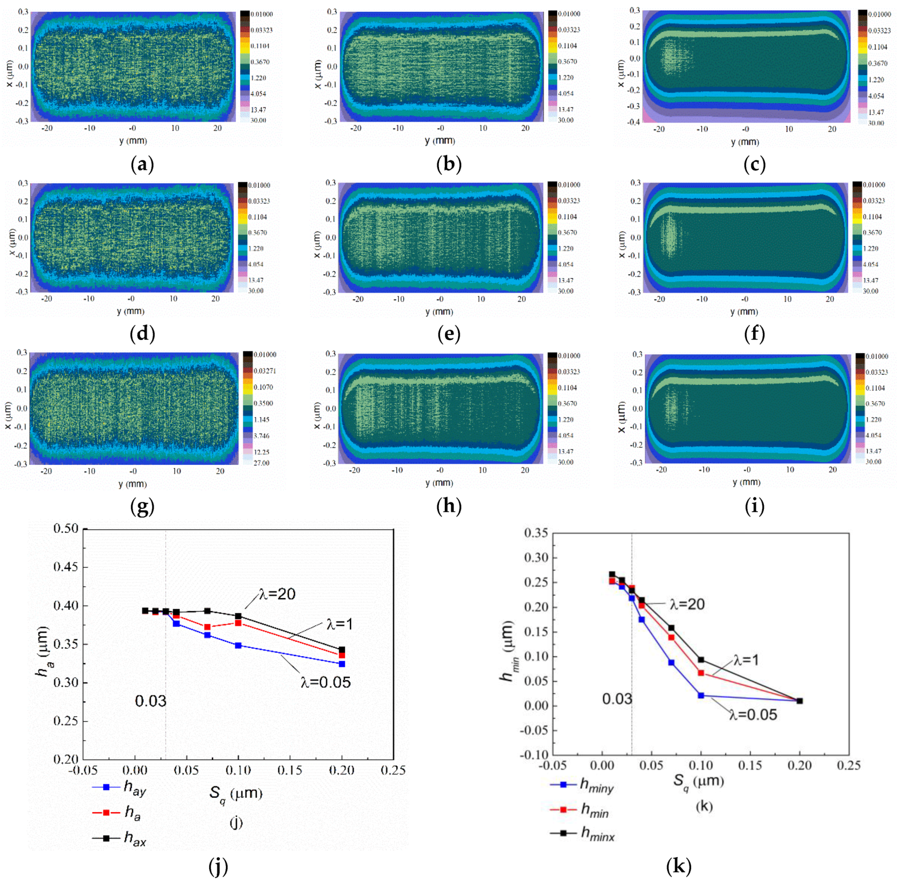
In each row of Figure 8a–e, film performs smaller fluctuations and light-colored area shrinks as roughness decreases, indicating the contact area is covered by thicker film thickness. Sq represents a degree of deviation from the mean value of surface height. Therefore, the large value of Sq is easy to form more obvious rough peaks and pits in contact area, which causes fluctuation amplitude of pressure to increase. Conversely, with a reduction of Sq from 0.2 μm to 0.01 μm average film thickness under all texture directions basically shows an increasing trend but individual values are deviated that due to the randomness of surface morphology in Figure 8. In Figure 8k, as Sq goes from 0.2 μm to 0.1 μm, the minimum film thickness increases from 0.01 μm to 0.09 μm (λ = 20) indicating that lubrication is transformed from mixed-lubrication to full film lubrication. However, further reduction of roughness has no significant effect on improving lubrication when roughness is less than 0.03 μm.
Texture direction can be represented by ratio of auto-correlation lengths. Three different texture directions are set to analyze the influence on film thickness (λ = 20; λ = 1; λ = 0.05). When λ is 0.05, texture direction is y direction.
It is worth noting that the cloud maps of film thickness in the y-texture direction had obviously more densely light-colored regions seen from each column of Figure 8a–i. Oppositely, fluctuation amplitudes of film thickness decreased and sparse light-colored regions were formed in surfaces having x-texture direction (λ = 20), especially on relatively rough surfaces. Moreover, among surfaces with three different texture directions, the average film thickness was the thickest on a surface with x-texture direction (λ = 20) when the roughness was same in Figure 8j. It also showed x-texture direction was conducive to improving the minimum film thickness in Figure 8k. When the texture direction was parallel to rolling direction, surface roughness was less of a hindrance to flow of the lubricant. Despite this, the effect of texture direction on lubrication was weakened as Sq was below 0.03 μm. Finally, the texture direction was set in the x direction (λ = 20) which was consistent with rolling direction and surface roughness was recommended to be 0.03 μm to optimize lubrication.
4.2.2. Effect of Skewness Sk and Kurtosis Ku
On the basis of initial optimization of texture direction and surface roughness, the effect of skewness and kurtosis on further improvement of lubrication will be studied in this section. Five different Sk values from positive to negative are combined with three different Ku (Ku1 = 3; Ku2 = 5; Ku3 = 8) together to form 15 different surfaces.
When changing the value of kurtosis in condition of Sk = 0, the pressure and film thickness at the central position of x direction are sliced for contrast shown in Figure 9a. Distinct fluctuations appear in film thickness as kurtosis is large, which is same as the trend in pressure. Until Ku grows to 5, a slope of the red line goes down in Figure 9b. In other words, the effect of kurtosis on average film thickness becomes weak in the interval of 5–8. Ku is an indicator which represents the sharpness or flatness of surface profile. When Ku is less than 3 the surface performs flat relatively, whereas it is with more sharp tops as Ku is larger than 5. However, the effect of kurtosis on improving film thickness is extremely limited. As a result, kurtosis can be used to reduce fluctuations of film thickness but it little helps to enhance thickness of film on a nearly smooth surface (Sq = 0.03 μm). All above, an appropriate value of Ku should be less than 3.
When the surface roughness is 0.03 μm and kurtosis is 3, Sk has no obvious effect on further improving lubrication. The five cloud maps in Figure 10a–e depict the film thickness formed in different surfaces when value of Sk is changed from −0.75 to 0.75. The light-colored area decreases slightly as Sk goes from positive to negative. It is seen from Figure 10f the average film thickness hardly changes when Sk continuously decreases. However, skewness makes only a small contribution to film thickness in a nearly smooth surface, it still helps to reduce the maximum pressure when it goes from positive to negative. There are more pits to retain lubricant in rough surface with lower Sk so that a small percentage of load may be supported by lubricant film, which helps the diminution of maximum pressure. Therefore, it is better to set Sk to a negative value.
The optimized surface with recommend skewness and kurtosis will further contribute to make the tapered rolling element retain in a full-film lubrication avoiding the occurrence of boundary lubrication and mixed-lubrication in typical working conditions of running high-speed trains, which will greatly reduce micropitting corrosion. Else, even if micropitting occurs, the contact area of the rigid contact will be increased and contact pressure will be reduced due to the relatively flat surface and more pits existing. As a result, the degree of influence on surface morphology will also decrease correspondingly.
5. Concluding Remarks
The conclusion of this paper can be summarized.
- On precondition of maximum-allowable axle load in high-speed trains, insufficient lubrication will occur when the temperature and acceleration increase and running speed of high-speed trains decreases. Therefore, considering of actual working conditions of high-speed trains, in this study, a certain working condition of simulation model was set as 70 °C ambient temperature and acceleration of 1.05 m/s2 and running speed of 25 km/h. As a result, mixed-lubrication is formed in that condition;
- When surface roughness was less than 0.1 μm, lubrication state could be transformed from mixed-lubrication to full film lubrication but it was less useful for improving lubrication when it was less than 0.03 μm. Texture-direction parallel to the rotation direction of rolling element was conducive to lubrication;
- When the surface of rolling element was nearly smooth, kurtosis less than three could reduce fluctuations of film thickness a bit. However, a negative value of skewness had little influence on film-forming of lubricant, it had some influence on reducing the maximum pressure of film.
RMS roughness of tapered roller bearing ring after polishing was about 20 nm by forced-induced rheological polishing [32]—a flexible processing technique. It completely met the machining requirement of surface RMS roughness in this study. The rolling element with specific skewness and kurtosis recommended in this study could be formed by laser composite texture processing technology [33] with corresponding laser parameters. The optimization for surface morphology of tapered rolling element plays an important role on improving lubrication, which made mixed-lubrication formed in some real working conditions transform to full film lubrication. The improvement in lubrication will reduce friction and wear of axle box bearing, which on one hand, reduces the occurrence of early failures and prolongs service life and on the other hand improves driving safety.
Author Contributions
H.W.: H.W. is with Patent Examination Cooperation Sichuan Center of the Patent Office. The simulation calculation of elastohydrodynamic lubrication and writing of this paper were done when H.W. was studying for master degree in Southwest Jiaotong Univesity and participated in Sichuan Science and Technology Program. H.H.: H.H. is a lecturer at Southwest Jiaotong University. A Feature Extraction Method for Vibration Signal of Bearing Incipient Degradation(SCI)’ & ’Blind Source Separation and Dynamic Fuzzy Neural Network for Fault Diagnosis in Machines(EI)’ were published when H.H. researched fault diagnosis. Analysis of lubrication and fault mechanism and revision of the paper were done when in charge of Sichuan Science and Technology Program. S.Y.: S.Y. is currently studying for master degree in vehicle engineering with Southwest Jiaotong University and researching intelligent fault diagnosis methods of rolling bearing. W.G.: Electric drive control of emus is studied when W.G. is a master degree candidate in Southwest Jiaotong University. All authors have read and agreed to the published version of the manuscript.
Funding
This research was funded by Sichuan Science and Technology Program, Grant Number 19GJHZ0061.
Conflicts of Interest
The authors declare no conflicts of interest.
Appendix A
| E | = Integrated elastic modulus, 2.198e5Mpa | = Load, N | |
| = Pressure-viscosity exponent, m2/N | = X-coordinate (rolling direction), m | ||
| = Hertzian contact radius, m | = Y-coordinate, m | ||
| = Radius of Hertzian contact circle, m | = Viscosity of lubricant, Ns/m2 | ||
| = Film thickness, m | = Viscosity coefficient at an ambient temperature, Ns/m2 | ||
| = Shear layer thickness, m | = Film thickness ratio | ||
| = Rigid central film thickness, m | = Density, kg/m3 | ||
| = Average central film thickness, m | = Density in ambient condition, kg/m3 | ||
| = The maximum Hertzian contact pressure, Pa | = Effective radius in x-z plane, m | ||
| = Film pressure, Pa | = Effective radius in y-z plane, m | ||
| = Length of the rolling element, m | u1,u2 | = Velocities of surface1 and surface2, m/s |
References
- Di Puccio, F. Analytical Modeling of an Oblique Edge Crack in Rolling Contact Fatigue. Math. Probl. Eng. 2018, 2018, 1–12. [Google Scholar] [CrossRef] [Green Version]
- Dowson, D.; Higginson, G.R. A Numerical Solution to the Elasto-Hydrodynamic Problem. J. Mech. Eng. Sci. 1959, 1, 6–15. [Google Scholar] [CrossRef]
- Chao-Ho, H.; Rong-Tsong, L. Advanced multilevel solution for elastohydrodynamic lubrication circular contact problem. Wear 1994, 177, 117–127. [Google Scholar] [CrossRef]
- Lugt, P.M. Modern advancements in lubricating grease technology. Tribol. Int. 2016, 97, 467–477. [Google Scholar] [CrossRef]
- Vengudusamy, B.; Kuhn, M.; Rankl, M.; Spallek, R. Film forming behavior of greases under starved and fully flooded EHL conditions. Tribol. Trans. 2016, 59, 62–71. [Google Scholar] [CrossRef]
- Cousseau, T.; Björling, M.; Graça, B.; Campos, A.; Seabra, J.H.O.; Larsson, R. Film thickness in a ball-on-disc contact lubricated with greases, bleed oils and base oils. Tribol. Int. 2012, 53, 53–60. [Google Scholar] [CrossRef] [Green Version]
- Yoo, J.-G.; Kim, K.-W. Numerical analysis of grease thermal elastohydrodynamic lubrication problems using the Herschel-Bulkley model. Tribol. Int. 1997, 30, 401–408. [Google Scholar] [CrossRef]
- Pandey, R.K.; Ghosh, M.K. Thermal effects on film thickness and traction in rolling/sliding EHL line contacts—an accurate inlet zone analysis. Wear 1996, 192, 118–127. [Google Scholar] [CrossRef]
- Sountaree, R.; Mongkol, M. Analysis of Two Surfaces in Line Contact under TEHL with Non-Newtonian Lubricants. Appl. Mech. Mater. 2011, 148, 736–742. [Google Scholar] [CrossRef]
- Bonaventure, J.; Cayer-Barrioz, J.; Mazuyer, D. Transition Between Mixed Lubrication and Elastohydrodynamic Lubrication with Randomly Rough Surfaces. Tribol. Lett. 2016, 64, 2–13. [Google Scholar] [CrossRef]
- Choo, J.W.; Olver, A.V.; Spikes, H.A. The influence of transverse roughness in thin film, mixed elastohydrodynamic lubrication. Tribol. Int. 2007, 40, 220–232. [Google Scholar] [CrossRef]
- Torabi, A.; Akbarzadeh, S.; Salimpour, M.R.; Taei, M. Effect of surface roughness pattern on transient mixed elastohydrodynamic lubrication. Surf. Topogr. Metrol. Prop. 2015, 4, 15001. [Google Scholar] [CrossRef]
- Marian, M.; Tremmel, S.; Wartzack, S. Microtextured surfaces in higher loaded rolling-sliding EHL line-contacts. Tribol. Int. 2018, 127, 420–432. [Google Scholar] [CrossRef]
- Taee, M.; Torabi, A.; Akbarzadeh, S.; Khonsari, M.; Badrossamay, M. On the Performance of EHL Contacts with Textured Surfaces. Tribol. Lett. 2017, 65, 85. [Google Scholar] [CrossRef]
- Mo, S.; Zhang, T.; Jin, G.; Zhu, S.; Gong, J.; Bian, J. Elastohydrodynamic Lubrication Characteristics of Spiral Bevel Gear Subjected to Shot Peening Treatment. Math. Probl. Eng. 2018, 2018, 1–12. [Google Scholar] [CrossRef]
- Zhu, N.; Hu, Y.-Z. A Computer Program Package for the Prediction of EHL and Mixed Lubrication Characteristics, Friction, Subsurface Stresses and Flash Temperatures Based on Measured 3-D Surface Roughness. Tribol. Trans. 2001, 44, 383–390. [Google Scholar] [CrossRef]
- Yan, K.; Wang, N.; Zhai, Q.; Zhu, Y.; Zhang, J.; Niu, Q. Theoretical and experimental investigation on the thermal characteristics of double-row tapered roller bearings of high speed locomotive. Int. J. Heat Mass Transf. 2015, 84, 1119–1130. [Google Scholar] [CrossRef]
- Xu, H. Analysis of Hydrodynamic Lubrication of Oil Film between Elastic Rolling Elements. Master’s Thesis, Qingdao University of Technological, Qingdao, China, 2011. [Google Scholar]
- Kauzlarich, J.J.; Greenwood, J.A. Elastohydrodynamic Lubrication with Herschel-Bulkley Model Greases. ASLE Trans. 1972, 15, 269–277. [Google Scholar] [CrossRef]
- Peiran, Y.; Shizhu, W. A Generalized Reynolds Equation for Non-Newtonian Thermal Elastohydrodynamic Lubrication. J. Tribol. 1990, 112, 631–636. [Google Scholar] [CrossRef]
- Nelias, D.; Antaluca, E.; Boucly, V.; Creţu, S. A Three-Dimensional Semianalytical Model for Elastic-Plastic Sliding Contacts. J. Tribol. 2007, 129, 761–771. [Google Scholar] [CrossRef]
- Liu, S.; Wang, Q.; Liu, G. A versatile method of discrete convolution and FFT (DC-FFT) for contact analyses. Wear 2000, 243, 101–111. [Google Scholar] [CrossRef]
- Litvak, M.Y.; Malyugin, V.I. Poly-Gaussian models of a non-Gaussian randomly rough surface. Tech. Phys. 2012, 57, 524–533. [Google Scholar] [CrossRef]
- Deng, S.; Jia, Q. Design Principle of Rolling Bearing; China Standards Press: Beijing, China, 2008. [Google Scholar]
- Yang, X.; Pan, L.; Xiao, H. Research on the influence of radial clearance to the load of four-row conical roller bearing based on boundary element method. J. Eng. Des. 2014, 21, 191–197. [Google Scholar]
- Wang, Y.; Liu, Y.; Zhang, G.; Wang, Y. A Simulation Method for Non-Gaussian Rough Surfaces Using Fast Fourier Transform and Translation Process Theory. J. Tribol. 2017, 140, 021403. [Google Scholar] [CrossRef]
- Hu, Y.-Z.; Zhu, N. A Full Numerical Solution to the Mixed Lubrication in Point Contacts. J. Tribol. 1999, 122, 1–9. [Google Scholar] [CrossRef]
- Wang, B.M. High. Speed Motor Car Assembly and Bogie; AARSC: Chengdu, China, 2008. [Google Scholar]
- Wang, X.L.; Gui, C.L.; Zhu, Y.B. Determination and research of rheological parameters of homemade grease. J. Tribol. 1997, 17, 232–235. [Google Scholar]
- Wang, Z.; Shen, X.; Chen, X.; Tao, D.; Shi, L.; Liu, S. Experimental investigation of EHD grease lubrication in finite line contacts. Friction 2018, 7, 237–245. [Google Scholar] [CrossRef] [Green Version]
- Wilson, W.R.; Kalpakjian, S. Low-Speed Mixed Lubrication of Metal-Forming Processes. CIRP Ann. 1995, 44, 205–208. [Google Scholar] [CrossRef]
- Li, M.; Lyu, B.; Yuan, J.; Yao, W.; Zhou, F.; Zhong, M. Evolution and equivalent control law of surface roughness in shear-thickening polishing. Int. J. Mach. Tools Manuf. 2016, 108, 113–126. [Google Scholar] [CrossRef]
- Xie, X. The Study on Anti-Stick-Slip Phenonmenon and Reducing Friction of Sliding Machine Tool Guideways Based on Laser Composite Micro Textures. Doctoral Dissertation, Jiangsu University, Jiangsu, China, 2018. [Google Scholar]
Figure 1.
Tapered rolling elements and plug flow region. (a) Tapered rolling element of high-speed trains and inner ring; (b) tapered rolling element; (c) plug-flow region and direction of grease flow.
Figure 1.
Tapered rolling elements and plug flow region. (a) Tapered rolling element of high-speed trains and inner ring; (b) tapered rolling element; (c) plug-flow region and direction of grease flow.

Figure 2.
Axle-box bearing.

Figure 3.
Surfaces of a tapered rolling element. (a) Surface of rolling element scanned by white light interferometer; (b) imitated surface of rolling element.
Figure 3.
Surfaces of a tapered rolling element. (a) Surface of rolling element scanned by white light interferometer; (b) imitated surface of rolling element.

Figure 4.
Experimental film thickness along axial direction with different thickener types.

Figure 5.
Simulation film thickness h and pressure P along y axial direction.

Figure 6.
Effect of temperature and velocity on lubrication (a0 = 1.05 m/s2, W = 9959 N). (a) T = 10 °C, pressure P and film thickness H of center line in y direction; (b) T = 70 °C, pressure P and film thickness H of center line in y direction; (c) average film thickness ha and the minimum film thickness hmin at different driving speeds and temperatures.

Figure 7.
Effect of acceleration on the lubrication (W = 9959 KN, v0 = 25 km/h, T = 70 °C). (a) Pressure P of center line in y direction; (b) pressure P and film thickness H of center line in x direction; (c) average film thickness ha and the minimum film thickness hmin at different acceleration.
Figure 7.
Effect of acceleration on the lubrication (W = 9959 KN, v0 = 25 km/h, T = 70 °C). (a) Pressure P of center line in y direction; (b) pressure P and film thickness H of center line in x direction; (c) average film thickness ha and the minimum film thickness hmin at different acceleration.

Figure 8.
Effect of surface roughness and texture direction on film thickness (a = 1.05 m/s2, T = 70 °C and v0 = 25 km/h). (a–i) Cloud maps of film thickness formed on surfaces with different Sq and λ; (j) The average film thickness ha in each texture direction with different roughness; (k) minimum film thickness hmin in each texture direction with different roughness. (a) Sq = 0.2 μm; λ = 0.05, (b) Sq = 0.07 μm; ë = 0.05, (c) Sq = 0.01 μm; ë = 0.05, (d) Sq = 0.2 μm; λ=1, (e) Sq = 0.07 μm; ë = 1, (f) Sq = 0.01 μm; ë = 1, (g) Sq = 0.2 μm; ë = 20, (h) Sq = 0.07 μm; ë = 20, (i) Sq = 0.01 μm; ë = 20.

Figure 9.
Effect of kurtosis Ku on film thickness and pressure (Sq = 0.03 μm, λ = 20, Sk = 0). (a) Pressure P and film thickness H of center line in x direction; (b) minimum film thickness hmin and average film thickness ha as Ku changing from 3 to 8.
Figure 9.
Effect of kurtosis Ku on film thickness and pressure (Sq = 0.03 μm, λ = 20, Sk = 0). (a) Pressure P and film thickness H of center line in x direction; (b) minimum film thickness hmin and average film thickness ha as Ku changing from 3 to 8.

Figure 10.
Effect of the skewness Sk on film thickness and the maximum pressure (Sq = 0.03 μm, λ = 20, Ku = 3). (a–e) Cloud maps of film thickness with different Sk; (f) average film thickness ha and the maximum pressure Pmax with Sk changing from −0.75 to 0.75. (a) Sq = 0.03 μm, λ = 20, Ku = 3, Sk = 0.75, (b) Sq = 0.03 μm, λ = 20, Ku = 3, Sk = 0.35, (c) Sq = 0.03 μm, λ = 20, Ku = 3, Sk=0, (d) Sq = 0.03 μm, λ = 20, Ku = 3, Sk = −0.35, (e) Sq = 0.03 μm, λ = 20, Ku = 3, Sk = −0.75.


Table 1.
Geometric parameters of the tapered rolling bearings.
| Parameters | Value | Parameters | Value |
|---|---|---|---|
| Length of rolling element, L (mm) | 48.9 | Angle of cone of outer raceway θ1 (°) | 9 |
| Average radius of rolling element R1 (mm) | 26.7 | Angle of cone of inner raceway θ2 (°) | 2 |
| Average radius of inner raceway R2 (mm) | 170.6 | Contact angle between rolling element and outer ring αo (°) | 11 |
| Arc radius of modified end Ry (mm) | 45.0 | Contact angle between rolling element and inner ring αi (°) | 8 |
Table 2.
Lubricant parameters.
| Parameter | Value | Parameter | Value |
|---|---|---|---|
| The yield stress in 10 °C, τy (Pa) | 556.79 | The yield stress in 70 °C, τy (Pa) | 348.3 |
| The plastic viscosity in 10 °C, ŋ0 (Pa.s) | 8.229 | The plastic viscosity in 70 °C, ŋ0 (Pa.s) | 0.899 |
| The plasticity index in 10 °C, α (Pa−1) | 0.696 | The plasticity index in 70 °C, α (Pa−1) | 0.929 |
| Environmental density of the grease ρ0 (kg.m−3) | 870 | The bulk density ρg (kg.m−3) | 7850 |
© 2020 by the authors. Licensee MDPI, Basel, Switzerland. This article is an open access article distributed under the terms and conditions of the Creative Commons Attribution (CC BY) license (http://creativecommons.org/licenses/by/4.0/).
Share and Cite
MDPI and ACS Style
Wang, H.; Huang, H.; Yu, S.; Gu, W. The Effect of Surface Morphology of Tapered Rolling Bearings in High-Speed Train on Grease Lubrication. Lubricants 2020, 8, 76. https://0-doi-org.brum.beds.ac.uk/10.3390/lubricants8070076
AMA Style
Wang H, Huang H, Yu S, Gu W. The Effect of Surface Morphology of Tapered Rolling Bearings in High-Speed Train on Grease Lubrication. Lubricants. 2020; 8(7):76. https://0-doi-org.brum.beds.ac.uk/10.3390/lubricants8070076
Chicago/Turabian StyleWang, Heli, Haifeng Huang, Sibo Yu, and Weijie Gu. 2020. "The Effect of Surface Morphology of Tapered Rolling Bearings in High-Speed Train on Grease Lubrication" Lubricants 8, no. 7: 76. https://0-doi-org.brum.beds.ac.uk/10.3390/lubricants8070076
Note that from the first issue of 2016, this journal uses article numbers instead of page numbers. See further details here.