1. Introduction
Tribology is the science and technology concerning the interaction of solid surfaces in relative motion. The word tribology derives from the Greek word “tribos” that means rubbing. The topics covered by this word are various and include the study of lubricants, lubrication, friction, wear and bearings [
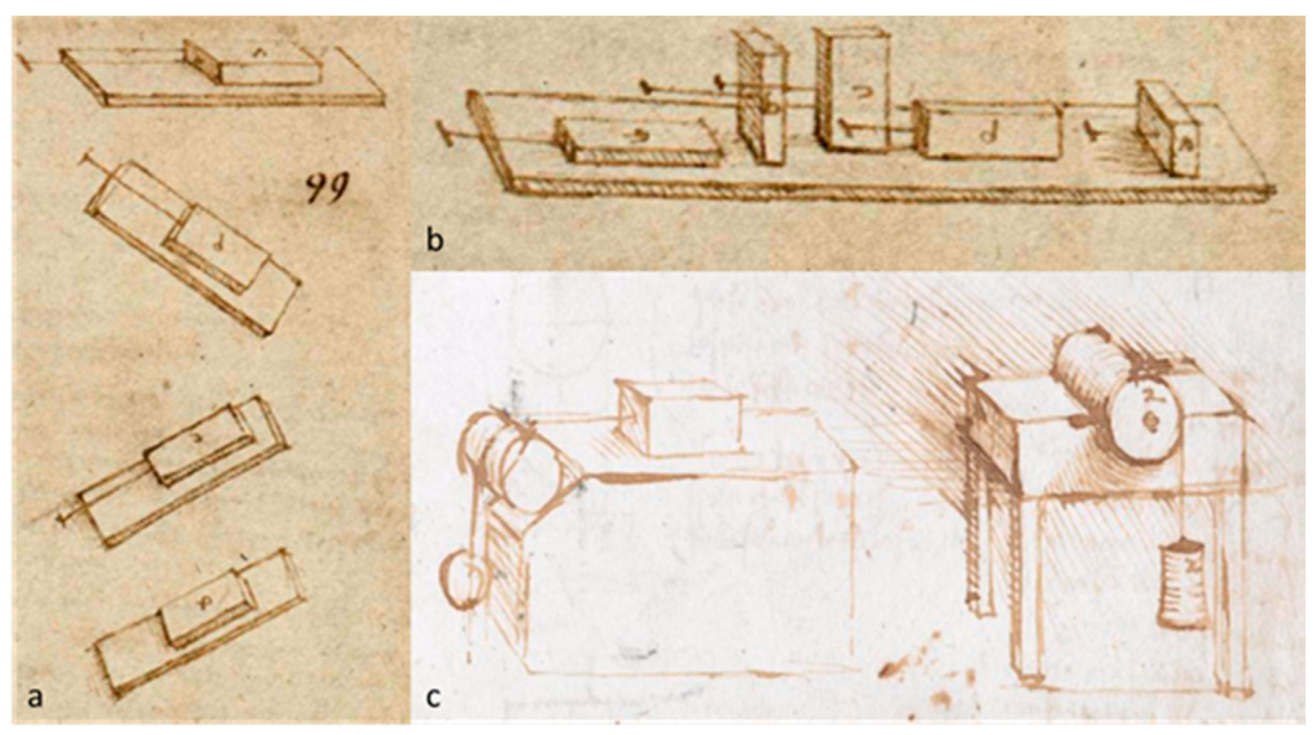
1]. Leonardo Da Vinci was one of the first to carry out and to report studies in the field of tribology, at the end of the XVth century; he had not only performed experimental studies concerning friction but he had also developed diverse ingenious schemes for the measurement of friction. His work remained unpublished until the twentieth century when Dowson [
2] presented his monumental study regarding the history of tribology. It is fascinating to note how the Da Vinci’s studies on friction still remain scientifically significant today [
3]. An example of Leonardo’s sketches published by Dowson is shown in
Figure 1.
Although this research topic has been studied for centuries, new analytical, numerical, and experimental methods have continued to evolve and be developed due to the intrinsic difficulty of the examination of materials’ tribological properties. Indeed, they do not only depend on the type of material and the relative properties, but also on the geometry, surface conditions and topography. In addition, the measurements are also affected by several working conditions such as the pressure distribution within the contact interface, relative speed, sliding distance, temperature and relative humidity [
4,
5,
6]. Consequently, extensive experimental studies adopting the most effective and robust methodologies become absolutely necessary for a deep understanding of tribological phenomena. To overcome the measurement and testing difficulties, a large amount of testing devices has been developed in the last centuries. These devices, variously called tribometers, tribotesters or friction testers (FTs), are widely used to study the friction phenomena of completely different materials, with a particular interest towards viscoelastic ones due to their advantageous characteristics, intrinsically variable in different application working ranges, and therefore particularly suitable for vibration and noise isolation or impact and impulsive shock absorption.
Starting from a particular interest in the study and in the characterization of the viscoelastic materials, the review aims to illustrate and to discuss the experimental devices designed and developed for the study of the rubber friction, being of crucial aspect in completely different contexts, e.g.,: shoe soles, O-ring sealing, conveyor belt and automotive applications, where the vehicle dynamics, the design of the apposite control systems, and the performance- and safety-focus are largely affected by what happens at the tyre/road interface in terms of friction generation mechanisms [
7,
8,
9,
10].
The review focuses on the devices that aim to study the friction between tyres and the road. It is worth highlighting that there is no limitation on the type of rubber that can be used for the friction and wear tests to be carried out with such kinds of devices, but the most commonly exploited testing conditions simulate the typical working contact conditions in the field of tyres, which are not necessarily reflected in other fields or standards. As for the latter point, it should be noted that there are some differences between the two main standards, the International Standards Organization (ISO) and the International American Standard for Testing and Materials (ASTM). For example, although in ASTM there are several indications concerning the proper selection of a method to measure the friction properties of a generic material, there are no any particular specifications for the determination of the rubber friction properties [
11]. In ASTM G115-10, the “Standard Guide to Measure and Report Friction Coefficients” is also included in the ASTM Friction Test Standards so that users can choose which method may be most suitable for a particular application [
12]. The methods for the determination of rubber friction are instead described in the ISO 15113 standards. This international standard refers to a linear movement and, unlike the previous ones, does not describe in details the test apparatus, but rather only provides a guide on the experimental arrangement, procedures and on the parameters to be taken into consideration to perform a robust measurement pipeline. Furthermore, the ISO standard gives indications about the normal loads and speeds to be used within testing, additionally providing procedures for the preliminary preparation of sliding surfaces under analysis [
13].
In the majority of theoretical studies on the frictional properties of materials, friction is represented using the friction model developed by Amontons and Coulomb, who claim that the frictional force is proportional to the normal force or load. However, as demonstrated initially by Bowden and Tabor [
14,
15] and by other authors later, Coulomb friction models are not fully reliable in case of viscoelastic materials like rubber [
16,
17]. Indeed, the main characteristics of the rubber friction, nowadays widely accepted and experienced, are dependent on normal force and sliding speed, temperature and a real contact area with highly-non-linear relations. These parameters play a key role in the study of the frictional behaviour of viscoelastic materials and can be used as a classification criterion to distinguish the devices and the studies to be conducted on rubbers and those to be performed in the tyre field. For instance, in a great amount of studies on rubber friction, tests are conducted at very low experimental speeds (lower than 1 mm/s) [
18], so that the temperature effect in the contact area can be neglected [
19] while tests conducted within the typical tyre working conditions should be generally performed at speeds in the order of meters per second.
Another crucial objective of a modern tribometer employable for tyre studies should consist in giving the possibility to work with specific samples of countersurface, i.e., an asphalt sample, since there could be a significant amount of reasons affecting the pavement characteristics: mix designs, plant operations, existing pavement conditions, or operations of the paver. It is quite obvious that it becomes really difficult to obtain the desired pavement characteristics in laboratory since even particular paving operations or peculiar mixture transformation during the compaction process phase may deeply modify the countersurface characteristics and therefore the viscoelastic behaviour of the tyre rubbers during the tyre-road interaction. For this reason, depending on a testing facility employed, it is always recommended to make sure to work with the pavement surface as similar as possible to the real one, extracting samples from a real tarmac surface for indoor testing or allowing to perform the analyses directly on track for outdoor testing with the aim to reproduce completely real test conditions. In case the test rig is employable for outdoor testing, it should be preferred since it allows one to not alter the geometries under study.
As already mentioned, the knowledge of the tyre friction behaviour and of the parameters affecting the phenomenon is an important topic both for academicians and industrial researchers, involving crucial aspects such as safety, performance, durability and environmental concerns [
5]. To this end, a series of test benches have been developed by universities, research institutions and tyre makers. The laboratory tests, in addition to being less expensive compared to outdoor tests, offer the possibility to carry out measurements in almost completely controlled environmental conditions, allowing one to vary sliding speed, normal load, temperature, and other parameters in wide ranges. Another important advantage of testing tyre tread block elements in the laboratory lays in the fact that the investigations can be made at a very early stage of the tyre development, when an eventual change within the compound composition is still relatively cheap and can be easily performed, optimizing as a consequence the tyre tread geometry of sipes or other design features. The goal of the test benches is to carry out tests, not only hardly reproducible outdoors, but also representative and transferable to large-scale tyre testing. A previous investigation of these devices was conducted by Moldenhauer [
20] in 2010 as part of his Ph.D. thesis. The work done by Moldenhauer has been deeply analysed, and, in the authors’ opinion, further enrichment is required in order to provide a more complete analysis of the devices developed in recent years. Furthermore, Moldenhauer’s study is limited to the description from the constructive point of view, while this review aims to analyse also the experimental outputs obtained, with the aid of published research references.
The paper is organized as follows: firstly, an insight on the theoretical aspects of the rubber friction is reported to provide the reader with a panorama of the main approaches and to point out the most critical aspects; then an overview of the experimental devices developed in the last fifteen years is illustrated. Such an overview cannot be complete, since there is a large number of devices used in universities’ research departments or in the tyre industry, not always accessible, but it still represents a quite complete report of the current techniques and methodologies, with particular reference to dry contact conditions. Tribometers can be classify based on the contact mechanism/geometry (area, line or point contact) of the tested material with the counter-face [
21]; the type of motion of the moving part [
22] (linear, rotary/rolling, reciprocating, or a combination); the element motion-actuated. Referring to the type of motion,
Section 3,
Section 4 and
Section 5 are respectively dedicated to Rolling FTs, Linear FTs and Other Types, which includes the devices that are not attributable to the other two categories.
2. Theoretical Description of Rubber Friction
The friction properties of elastomers such as rubber have been extensively studied for decades [
23,
24,
25,
26]. The tribological properties of rubber depend on many parameters, e.g., surface roughness, speed, normal load, lubrication, temperature and material properties. A fundamental study in this field was conducted by Grosch in his pioneering work [
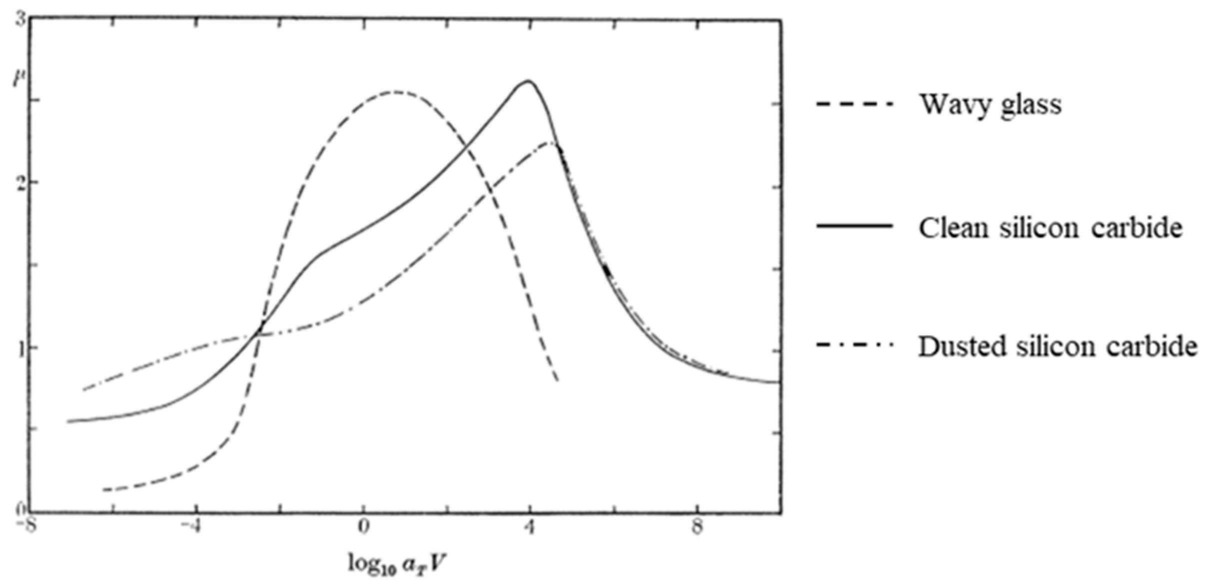
25], where different types of rubber were experimentally analysed on diverse hard surfaces, mentioning two distinct processes taking part at the generation of the friction phenomena: the adhesion, akin to a molecular relaxation process, and a deformation process in which energy is lost due to the cyclic stress of the rubber due to the surface roughness [
19], also known as the hysteretic component of friction. The friction coefficient evaluations obtained from experimental studies or mathematical models are usually plotted on a graph as a function of the sliding speed, this kind of representation is also called a “master curve”. This curve can be also parametrized for other variables such as load and temperature. The master curve of rubber on a rigid rough surface exhibits, in general, two distinct peaks. The first, being attributed to the adhesive component of friction, occurs in general at low sliding velocity, whereas the second one, referring to the hysteretic contribution occurs at higher sliding velocity [
27]. A typical example of a master curve is represented in
Figure 2, where the friction coefficient for a styrene butadiene rubber (SBR) rubber sliding on three different surfaces is reported.
Subsequently, other researchers such as Greenwood and Williamson (GW) [
28] introduced a concept involving the contribution of the true contact area on friction. In particular, the formulation of the GW theory is based on Archard’s [
29] previous idea of multi-asperity contact. They approximated the roughness of the surface as an ensemble of spheres having the same radius randomly distributed over the mean plane to take into account of the surface statistics.
Over the years, some other studies such as the ones by Bush at al. [
30,
31], Heinrich, Kluppel and others [
32,
33,
34] proposed further contributions based on the original GW theory. Multi-asperity contact models, based on Greenwood and Williamson theory, represent one of the two most used approaches to account for the true contact area on the friction mechanisms. Another widely adopted approach has been developed by Persson [
35], whose theory, in contrast to the GW models, removes the assumption that the true contact area is smaller than the nominal contact area [
36], considering the extreme case of full contact conditions between a rigid rough surface and an initially flat elastic half-space. Such theory takes partial contact into account requiring that, in case of adhesionless contacts the stress probability distribution vanishes when the local normal surface stress is fading. It also assumes that the power spectral density (PSD) of the deformed elastic surface is the same as the rough surface below [
37]. The theory provides formulas, needing as inputs only the PSD surface and the elastic properties of the contacting bodies. A recent study by Carbone and Bottiglione [
38] compared the two different approaches, stating that Persson’s rubber contact and friction theory, and the subsequent theories based on it, are more accurate. Although theories on rubber friction have evolved over the years, they still present diverse limitations associated with the adhesive and the viscoelastic component of friction [
39]. Under this light, appears evident the centrality of an experimental approach and how important the setup of the different testing fixtures is.
3. Rolling Friction Testers
This category of devices makes use of the principles of double disc tribometers, which consist of two discs rotating against each other. This kind of tribometers are also known with different names such as: ring on ring, roll on roll, rolling sliding apparatus, etc. In the field of tyres, these tests equipment reproduce, on a small scale, the design of the “tyre on drum” test machine.
Liu et al. [
40,
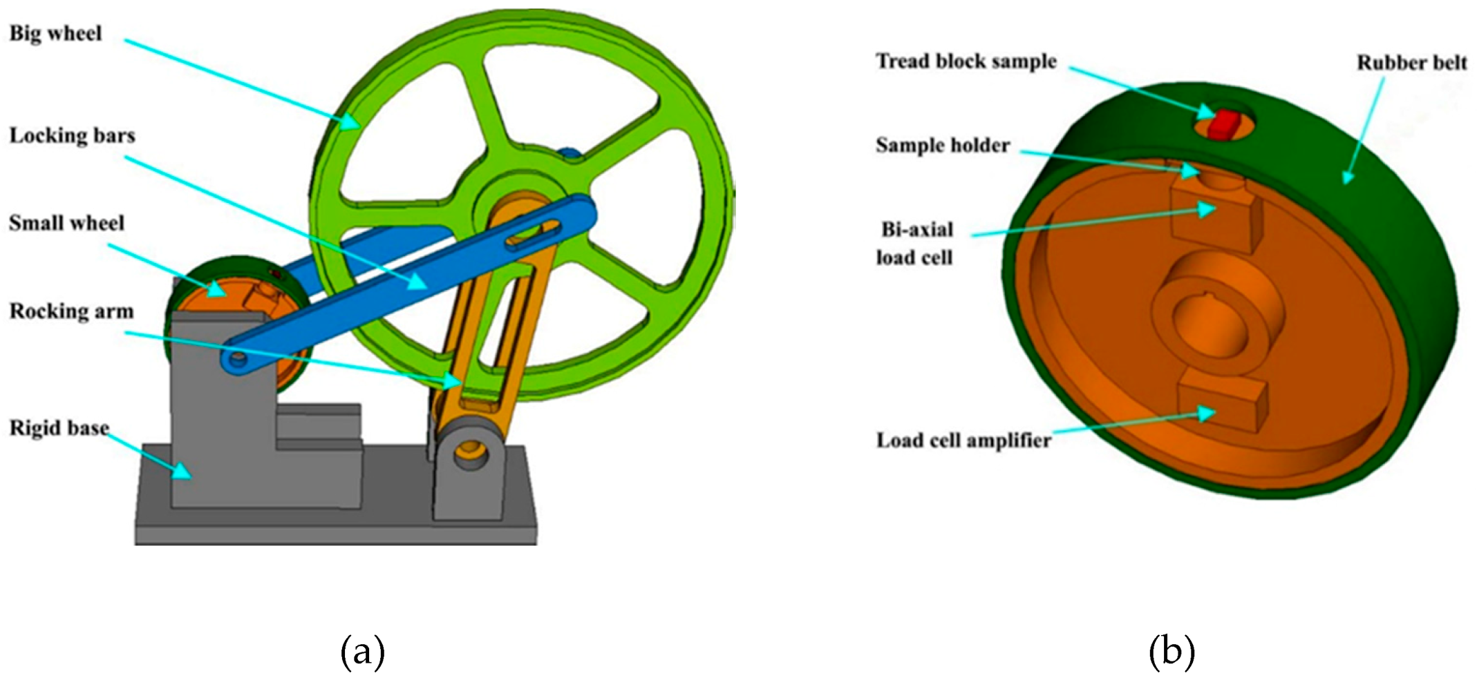
41] have developed a high-speed rolling test rig aiming to simulate the impact and release mechanisms of tread block. As shown in
Figure 3, the device consists of a small wheel with a rubber belt coating, which drives a big wheel with a steel surface. The small wheel is mounted directly on a solid base and is driven by an electric motor, while the big wheel is mounted on a solid base by a moving rocking arm; lastly another couple of stiff arms are used to lock the wheel shaft position, to obtain the desired value of interference between the two wheels and to apply a compression to the tread block sample.
The main elements of the driving wheel are:
an electric motor, driven by an inverter (DF51, Moeller,)
a rubber belt, attached around the outside surface, with a hole to allow installation of the tread block sample
a biaxial load cell embedded inside and interposed between the tread block and the sample holder
a load cell amplifier
a thermocouple placed in contact of the sample, used to measure operating temperature
a slip ring unit
The main technical specifications are summarized in the
Table 1.
With the aim of the investigation regarding the contact forces between the tread block and the road, the authors conducted several tests, varying both the speed (at three speed levels of 150, 300, 600 rpm), and the interferences in the 0.1–0.3 mm range.
With the high-speed rolling test rig, it is possible to simulate the impact and release mechanisms of a tread block. The main drawback of this device is related to the use of the asphalt surface, for two reasons: firstly, it is difficult to make a curved asphalt sample; secondly, when the big wheel is covered by a rough surface, the tread-block sample comes in contact with the wheel only partially.
A different approach for rolling FT is proposed by Lundberg et al. [
42], involving a new experimental device that allows detailed studies of the rolling contact force between a tread block and a relative substrate. The device, called compact internal drum (CID), aims to simulate a realistic impact and release mechanism for the tread block-substrate contact and enables force measurements.
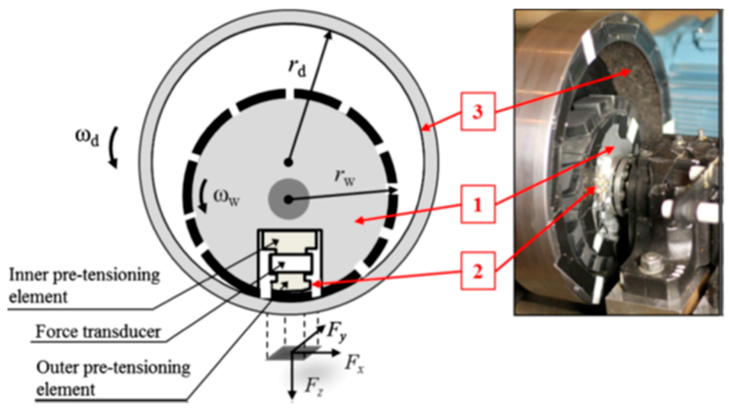
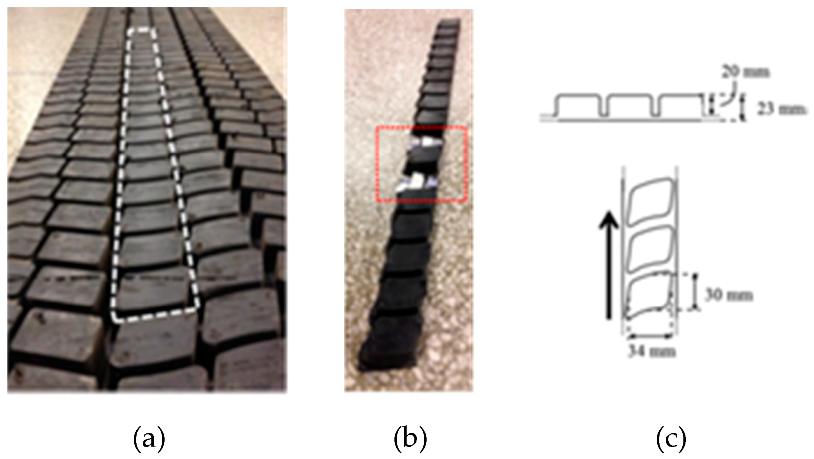
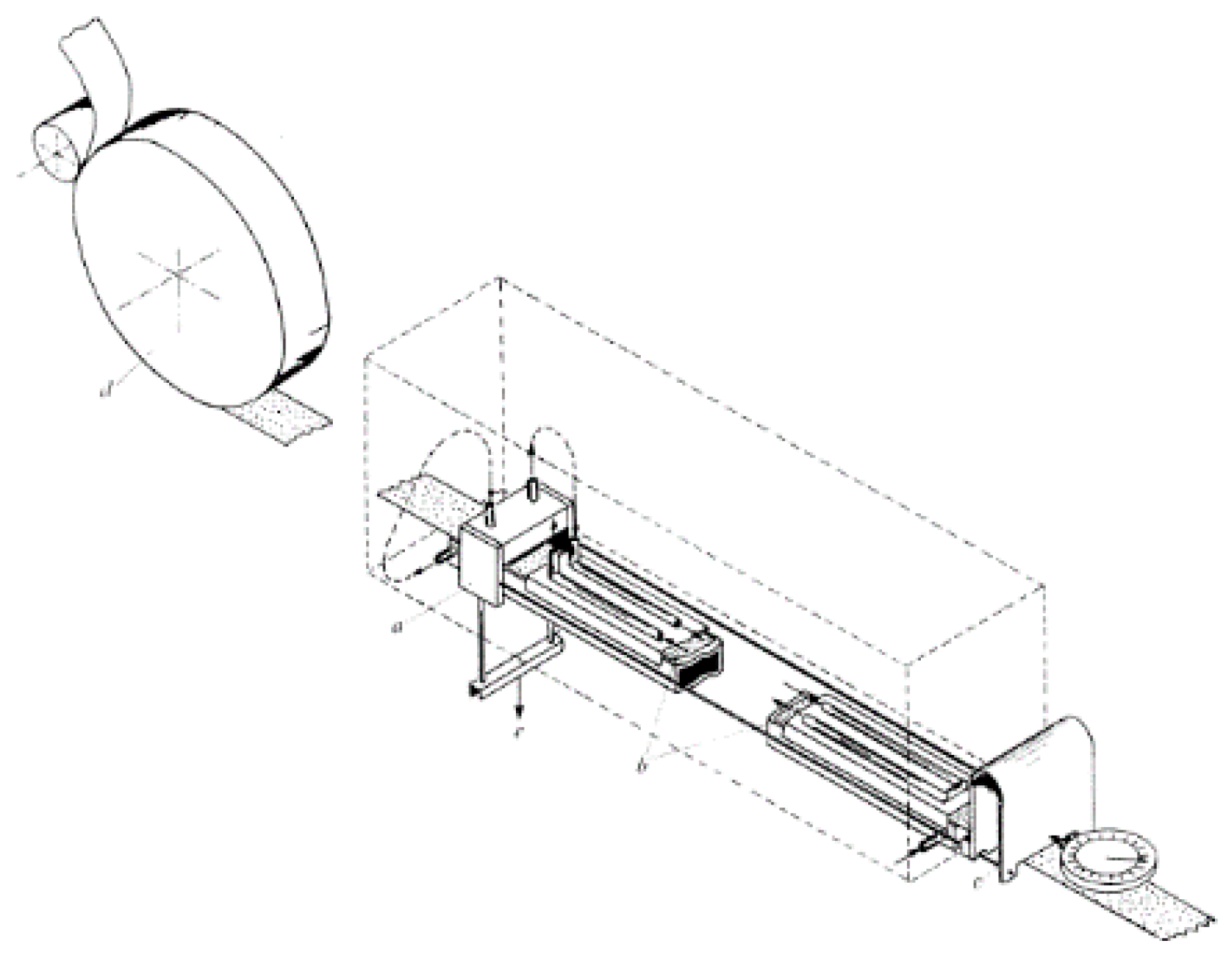
Figure 4 shows the core of the device, consisting of two wheels: a solid metal wheel (1) with a cut-out window to accommodate a force link (2) interposed between the tread block sample and the inner face of the wheel. The tread sample is obtained by cutting a tread strip from a truck tyre re-treading material, like the one shown in
Figure 5. The solid wheel rolls on the inner surface of the second wheel (drum) (3), that can be covered by an interchangeable rough surface.
In
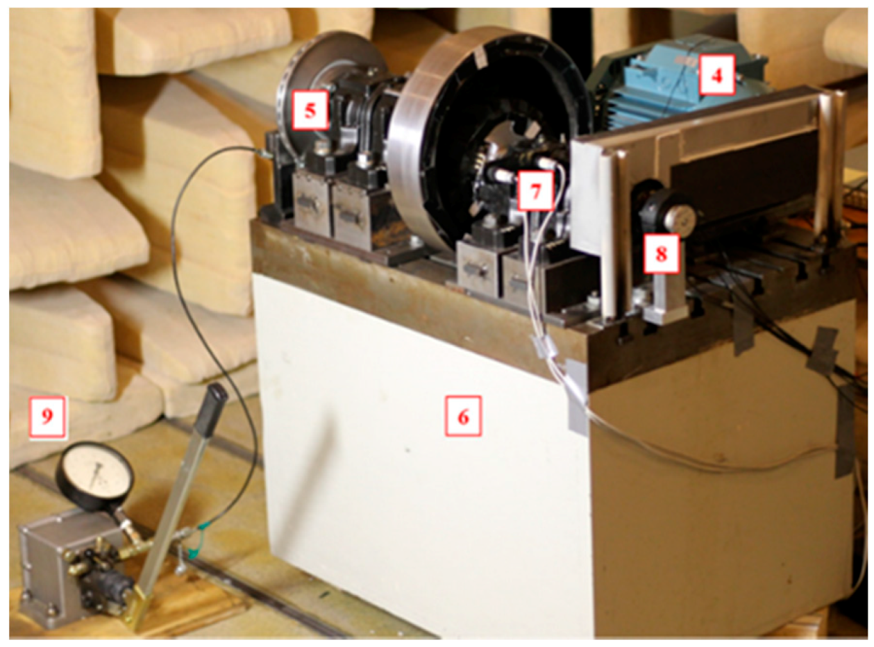
Figure 6, the test rig is depicted in all its components, the highlighted (numbered) components complete the device description. The solid wheel is driven by an electric motor (4), controlled by a driver, which transmits the movement directly to the shaft of the solid wheel, through three belts, and subsequently from this to the drum through the friction forces established between the rubber mounted on the periphery of the solid wheel and on the inner surface of the drum. The drum shaft is equipped with an automotive-derived disc brake (5), used to deaccelerate the drum; furthermore, it is possible to vary the brake pressure by means of a manually adjustable hydraulic system (9). An optical sensor (7) is used to measure rotation speeds, while a resistive temperature sensor is introduced into a tread block adjacent to the sample tread block, allowing to estimate the real temperature without damaging the reference sample. The data from the sensors are transmitted from the rotating part to the non-rotating data acquisition system via an HBM SK12 slip ring (8). It is possible to prescribe the desired compression load between the tread block sample and the rough surface of the drum, by shifting vertically the shaft of the drum. The normal load between the sample of the tread block and the rough surface of the drum is quantified by measuring the bending deformation induced in the strain gauges mounted on the drum shaft. The test rig is mounted on a concrete block (6). The main technical specifications of the rig are listed in
Table 2.
By adopting this kind of test rig the contact forces between tread block and roads under different conditions can be investigated. Indeed, the test rig layout allows to vary: the velocity, the normal load and the braking pressure, with or without driving torque. In. [
42], Lundberg et al. showed the experimental results obtained varying the main parameters involved.
The main advantage in the use of the CID lies in the possibility to operate in a wide range of speeds; furthermore, if compared with the device analysed in the previous section, it offers the possibility to measure the forces generated in the tyre/road contact both in free-rolling conditions or in sliding conditions, simply varying the braking force. Again, a drawback of this layout is related to its geometry that imposes the use of curve asphalt samples which are particularly difficult to produce.
4. Linear Friction Testers
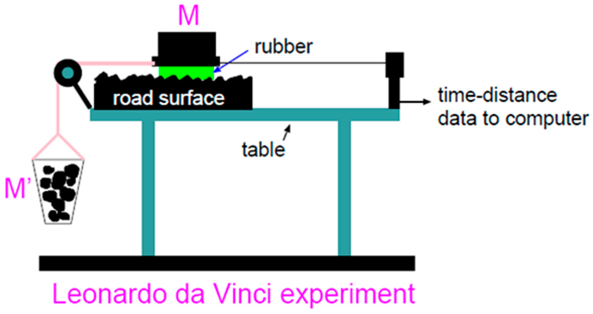
The first linear friction tester (LFT) was developed by Leonardo da Vinci at the end of the fifteenth century and the concept of his device is still valid and adopted in recent studies [
43,
44]. Indeed, in their recent study [
45], Tolpekina and Persson analysed adhesion and friction in tyre tread compound, conducting an experimental investigation trough a LFT like the Leonardo da Vinci type. The schematically representation of the tester is available in
Figure 7.
The layout of the device is as simple as smart: it consists of a table on which a substrate is fixed and on which a rubber sample can slide. The latter can be loaded by means of a calibrated weight and moved by adding a weight in a container connected to its free end. Nowadays this type of test rigs is widely used, perhaps is the most used device in the study of friction and wear in tyre tread block.
In the modern era, Grosch’s tribometer is considered one of main examples of this category of testers [
25]. The device, shown in
Figure 8, consists of a test sample pad of about 2.5 cm
2 and 0.5 mm thick, attached to a sample holder and pressed against the test surface by a calibrated load. To measure the frictional force a U-spring dynamometer is connected to the holder by means of two steel wires. The test surface is driven by a motor coupled to a multi-ratio gear box, that provides sliding speeds ranging from 10
−6 to 3 cm/s. The sample and the track surface are enclosed in a temperature and humidity-controlled chamber.
Over the years, researchers have adopted various layouts to improve the friction coefficient measurements, evolving from the principles developed by Grosch’s works. Given the wide range of existing LFT devices for convenience, in the following, they are distinguished in two categories:
4.1. LFT Surface in Motion
The layout of LFT in which the moving part is the rough surface is a setup adopted by numerous researchers Lorenz et al. [
46,
47] carried out a rubber friction study for a tread rubber sample sliding on an asphalt road specimen taking advantages from this kind of setup.
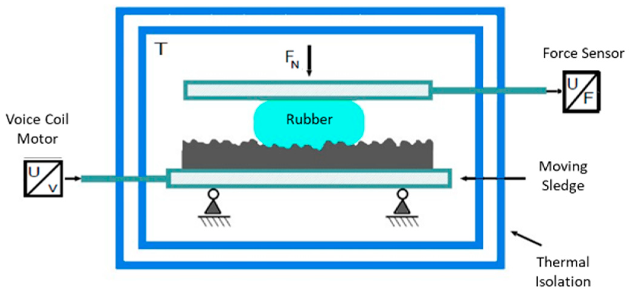
More in detail, the friction measurements have been carried out using an in-house developed test rig, schematically shown in
Figure 9, composed by a lower steel sledge where the rough surface sample is clamped. The sledge is moved using a voice coil actuator, capable to generate a constant force. To control the actuator and its speed, the position of the sledge is measured using an analog magneto-strictive linear position encoder. On the upper side of the device there is an aluminium plate which on one side (the lower surface) allows to attach the rubber sample; on the other (upper surface), encapsulates a heating system; in this way it is possible to ensure a homogeneous distribution of the heat, ensured by inserting the device in a temperature-controlled chamber where the temperature can be controlled. The nominal normal load can be varied through the application of calibrated weights on the upper plate, allowing the contact force between tread sample and rough surface to be changed. The friction force is measured using a bi-axial load cell mounted in line with the sample holder. The main technical specifications are shown in
Table 3.
With the LFT, the authors aimed to investigate contact forces between tread blocks and road surfaces. The tests were conducted under different sliding conditions, varying both the velocity in the range 10
−6 < v < 10
−3 m/s and temperature at three different levels, −8 °C, 20 °C, 48 °C, respectively. The rubber test sample is cut out from a tread compound used on summer tyres for passenger car. The measured friction forces are then shifted according to the Williams, Landel and Ferry (WLF) equation [
48].
It is worth noting that this device allows measurements only in a small range of velocities and loads, therefore it is not suitable to simulate the real conditions of tyre/road contact. A similar LFT layout was adopted by Lang and Kluppel [
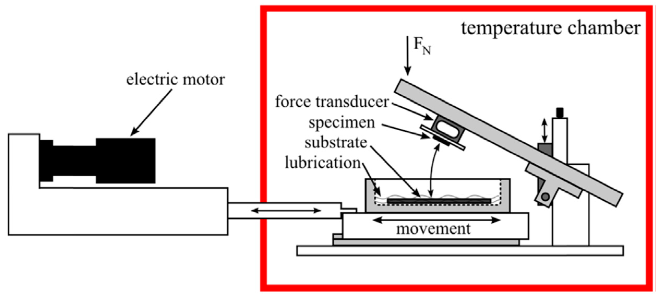
49], designed for the experimental investigation of the load and temperature dependences upon the dry friction behaviour of racing tyre tread compound in contact with rough granite. The device employed for the study was constructed and developed at IMKT, University of Hannover. The scheme of the device is shown in
Figure 10.
The test rig is composed by the following main elements: An electric motor; an arm on which a rubber specimen is housed; a force transducer, interposed between the rubber sample and the arm; a tank, moved by the motor through an actuator, to host a road specimen; a granite road specimen and a temperature chamber. The nominal normal force acting on the tread sample can be varied. Through the application of different values of the load, on the upper side of the arm, it is possible to get a different value of the contact pressure between tread sample and rough surface. The main technical specifications of the test rig are shown in
Table 4.
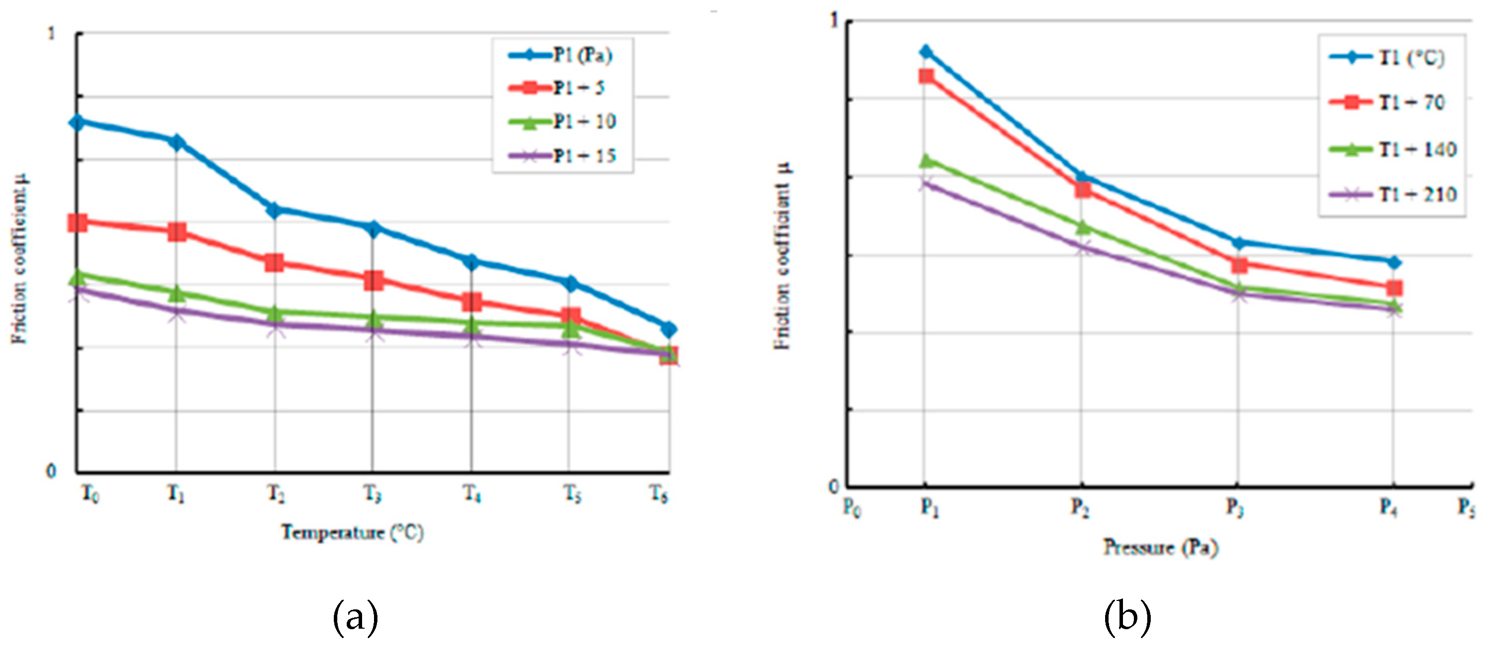
The tests, aimed to investigate the friction coefficient, were conducted under different sliding conditions, varying both the velocity and the temperature aspects. Measurements in different velocity conditions from 0.1 mm/s to 300 mm/s have been carried out changing the load between 1 bar and 7 bar at six different temperatures (at 2 °C, 10 °C, 20 °C, 40 °C, 70 °C and 100 °C).
The rubber test sample was cut from a tread compound of a racing tyre and moved in sliding contact on two different granite surfaces: coarse and fine. In [
49] is reported the friction coefficient carried out form the experimental activity, both for the coarse and for the fine granite, at different load levels in the range 1–7 bar and for six different reference temperature.
Compared to the other FTs presented in the review, the device adopted by Lang and Kluppel seems to be one of the most complete since it allows one to operate in both dry and wet conditions; to investigate the effects of the utilization of interface lubricants and the use of real asphalt and tread samples. Moreover, a wide range of applicable loads and the temperature control environment allows measurements in almost all tyre-road contact operating conditions of passenger or racing automotive applications.
The last device belonging to this category is reported in O’Neil et al.’s [
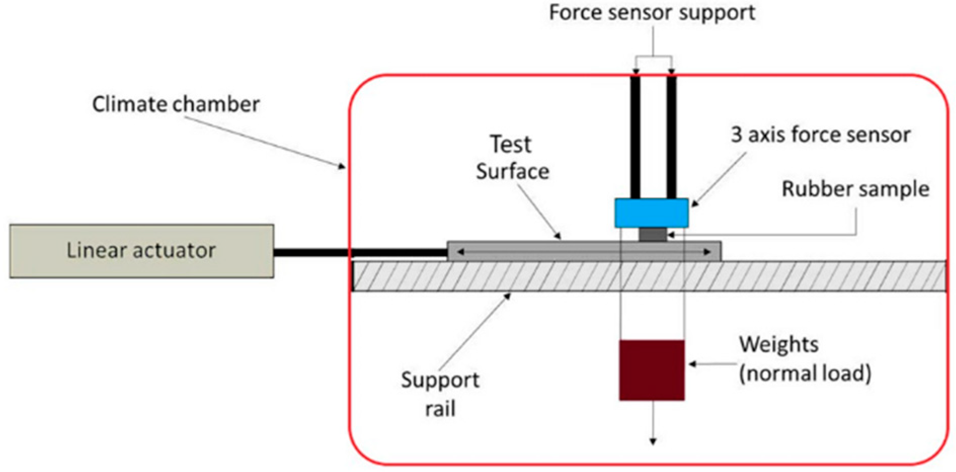
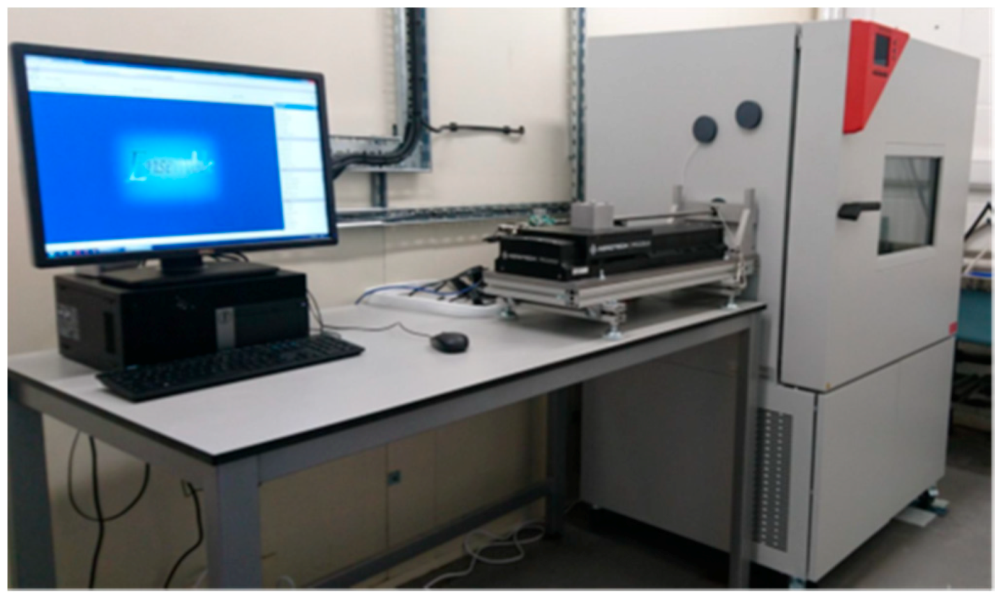
50] studies, where the authors performed an experimental investigation to predict tyre behaviour on different road surfaces. To perform friction measurements, the authors have used a LFT. The device, constructed at the University of Surrey (Guildford, UK), has a layout very similar to the previous one, reported in its schematic representation and in the real arrangement in
Figure 11,
Figure 12 and
Figure 13.
A direct-drive linear motor, located outside the climate chamber, moves a sledge where the test surface is clamped. The sledge is embedded in the climate chamber and is supported by a linear rail system. The rubber sample is placed above the test surface by a rigid frame, between the sample holder and the frame is interposed a three-axis force sensor. The tread sample is pressed against the test surface through the application of calibrated weights on the upper side of the sample holder; in this way it is possible to vary the contact pressure between tread sample and rough surface. The main technical specifications are summarized in the
Table 5.
In [
50], tests were conducted on a rubber sample cut from a passenger car tyre and driven on sandpaper. Measurements have been carried out for different velocities from 0.03 mm/s to 10 mm/s at sixteen different temperatures ranging from −40 °C to +50 °C. The main technical difference between the above test rig and the one at IMKT (University of Hannover), regards only the maximum sliding speed reachable (about 0.05 m/s).
4.2. LFT Rubber Sample in Motion
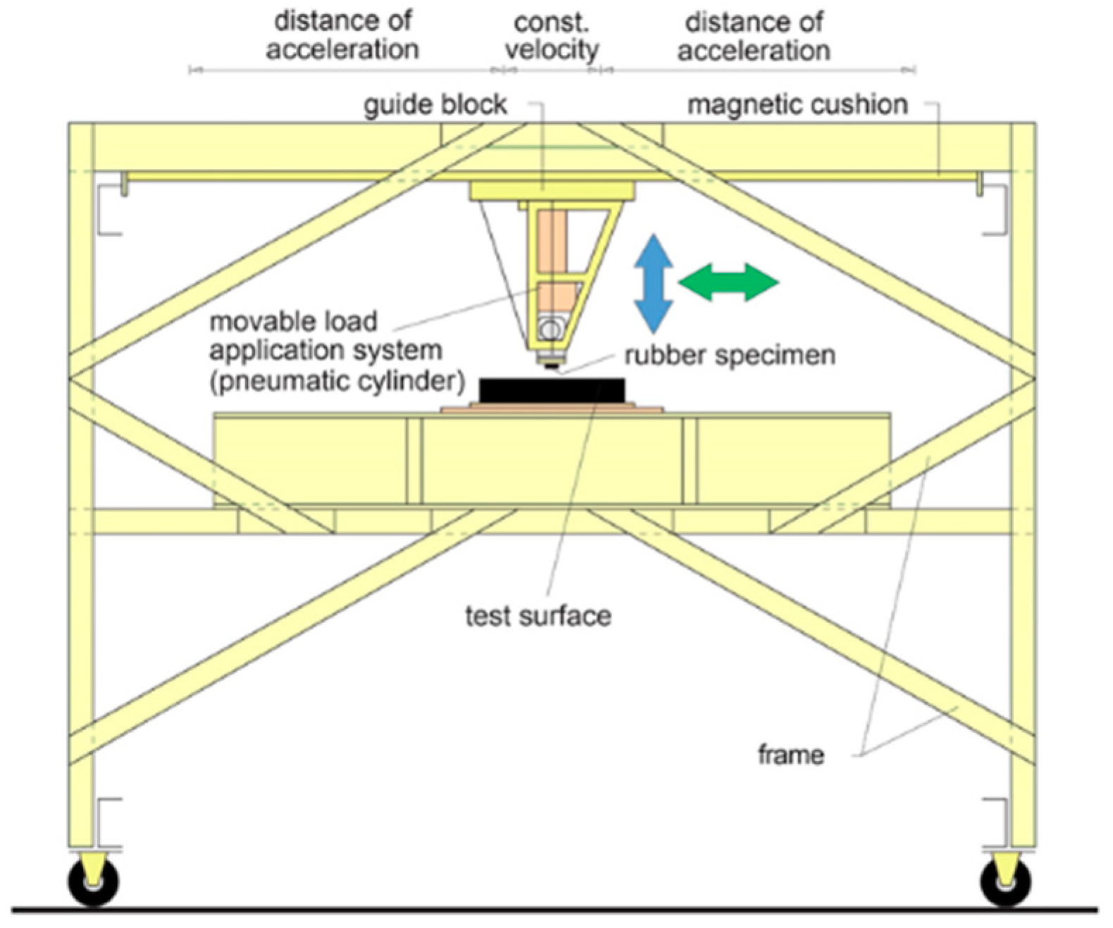
In the current section a second family of LFT is analysed, characterized by the fact that the moving part is the tread block sample. A first example of this kind of layout is reported in the studies conducted by Lahayne et al. [
52,
53], in which the results of the friction coefficient measurements are carried out using a LFT developed at the Institute for Mechanics of Materials and Structures at Vienna University of Technology [
54]. The schematic representation and the core of the test bench are shown in
Figure 14.
The LFT consists of a rigid frame that contains both interchangeable test surfaces and a linear motion unit. The linear unit holds and pulls a sledge that incorporates both the tread block specimen and the test equipment. This sledge contains: a pneumatic system used to generate the normal load, a sample holder and a piezoelectric force sensor which measures the contact force between tread sample and rough surface. The frame was specially designed to hold a high-speed camera and a pyrometer to acquire the deformation and the temperature of the sample during the tests. The device is located in a climate chamber.
The main technical specifications are summarized in
Table 6.
The tests were performed by the authors under different sliding conditions, varying velocity, temperature, rubber materials and rough surfaces. In order to know how the temperature of the tread samples changes during the tests, an optical pyrometer pointing at the tread sample, measures the temperature on the contact surface in the initial position; while a thermocouple introduced into the tread block to record the temperature data during the test. In [
52] are discussed the friction coefficient measurements for six tyre materials done on concrete and asphalt at 18 °C and 27 °C. Also this test bench offers the possibility to operate in both dry and wet conditions.
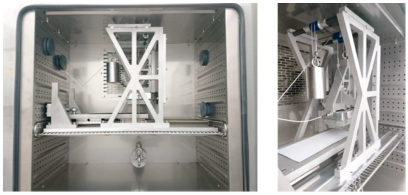
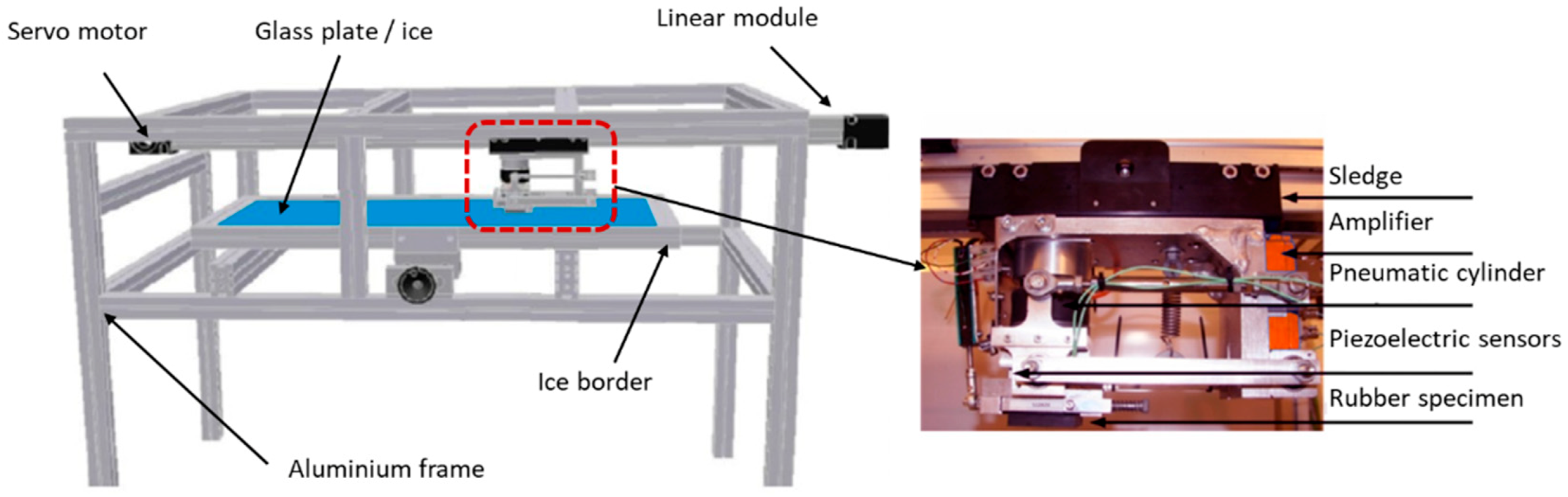
At Aalto University of Technology (Helsinki Finland), another example of this kind of LFT, called mini-μ-road (MMR) FT, was developed [
56,
57]. The MMR, presented in
Figure 15, was specifically designed for low-friction testing [
58].
The experimental device consists of an aluminium frame that contains both the interchangeable test surfaces and a linear motion unit. It is equipped with a servomotor, whit a power of 4 kW, to drive a sledge supported by a linear rail system. The sledge holds and pulls a rigid frame that incorporates both the tread block specimen and the test equipment. This frame allows to host: a pneumatic cylinder used to generate the normal load, a sample holder, two piezoelectric load cells which measure the contact force between tread sample and rough surface and an amplifier module. The entire system is located in a climate chamber and is controlled by LabView. The main technical specifications are summarized in
Table 7.
In their paper [
59] Kärkimaa, and Tuononen presented the results of a study conducted on tread rubber sample sliding on an asphalt road specimen. The tyre tread samples were provided by Nokian Tyres. The tests were conducted under different sliding conditions, varying the velocity and temperature. Measurements for different velocities from 1 mm/s to 1000 mm/s have been carried out at different temperatures with uncertainty about +/− 1 °C.
This device has a layout very similar to the one at Vienna University, the only technical difference is the maximum sliding length that the device can reach, which in this case is about 1000 mm. Among the examined devices, this is the second for sliding length.
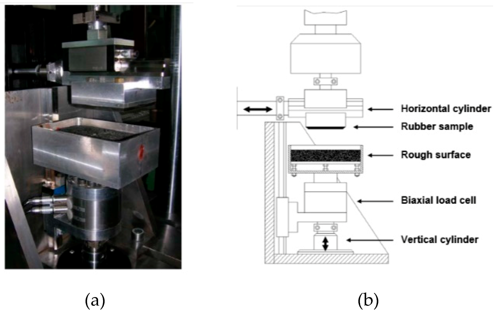
Le Gal [
60] in his Ph.D. thesis worked on a characterization of the friction coefficient by means of two different testing methods. Previously, a stationary friction experiment was performed using a modified Zwick universal test rig and subsequently a modified version of the MTS biaxial servo-hydraulic testing facility was used to extend the range of measurements and to simulate the typical loads in tyre application.
Figure 16 shows a complete view of the MTS modified test facility layout.
It consists of a vertical cylinder positioned at the base of machine’s floor, connected in series with a biaxial load cell for measures both the normal and the tangential force. An aluminium tank mounted on the load cell holds an interchangeable test surface and allows the possibility to use a liquid in order to simulate wet condition. A second cylinder, perpendicular to the vertical axis, on which is mounted an aluminium plate allows both the horizontal movement, and the possibility to fix the rubber sample with a maximum size of 80 × 80 mm
2; both axes (cylinder) are displacement controlled. The contact pressure between the rubber sample and rough surface can be varied assigning different displacement values to the vertical axis; on the other side, assigning different displacement time histories to the horizontal axis, it is possible to obtain different sliding speeds. The main technical specifications are summarized in
Table 8.
Figure 17 depicts a typical measure of the contact forces. Figure refers to tests conducted at the sliding speed of 4 mm/s on a styrene-butadiene rubber (SBR) sample filled with 60 phr N339 and at the experimental pressure of 0.25 MPa between the rubber sample and the fine asphalt sample.
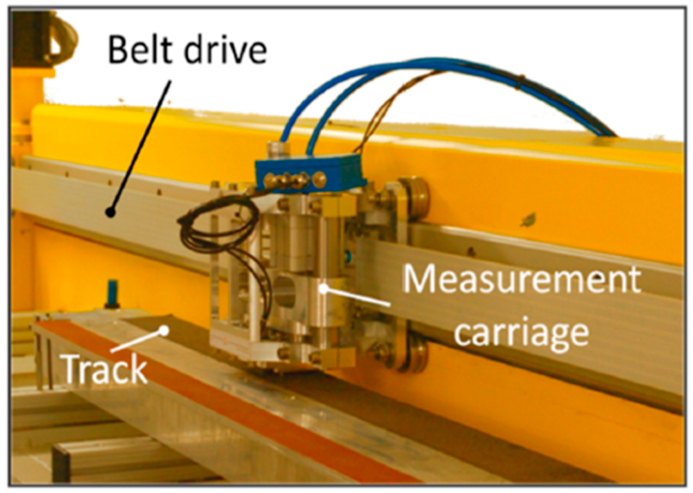
The high-speed tribometer developed at the Institute of Dynamics and Vibration Research (IDS) at the Leibniz Universität Hannover [
61], also belongs to the LFT rubber sample in motion category. Such tester, also called HiLiTe, along with HSLFT manufactured by Altracon [
62,
63] is representative for a class of test rigs able to reach high velocities. The HiLiTe test machine, shown in
Figure 18, was designed and developed in such a way to be able to simulate all relevant tyre testing conditions.
It consists of a 5 m long linear guide rail in which a carriage is driven by a servomotor with a toothed belt and performs a linear movement. The carriage mounts all the test equipment and the rubber sample. Embedded on the carriage is a pre-stressed helical spring by means of which it is possible to generate the normal load between the sample and the road surface. It is actuated by a pneumatic actuator through which it is possible to set the normal force in the range of 23–1000 N. The carriage also contains a bi-axial piezoelectric force transducer which measures the normal and tangential components of the contact force between the tread sample and the test surface. The track can be equipped with any surface. The entire test bench is located in a climatic chamber so that experimental investigations can be conducted in a temperature range from −25 °C to 60 °C. The climate chamber also allows humidity control. The main technical specifications are summarized in
Table 9.
The HiLiTe machine allows to use a number of different test tracks to reproduce a great variety of outdoor environmental conditions.
The Researchers of University of Hannover have performed several experimental investigations by means of HiLiTe [
65,
66] adopting concrete and asphalt tracks for dry and wet testing as well as test tracks made from ice and snow. In their paper Rosu et al. [
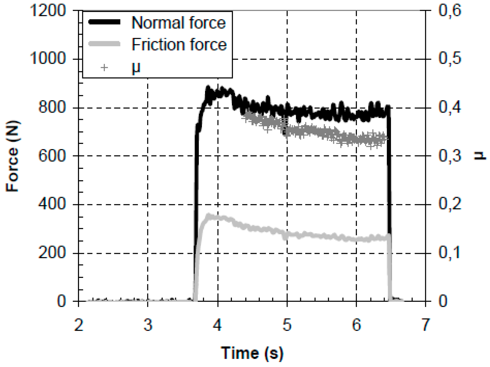
64] performed an experimental investigation of the contact between an aircraft tyre rubber and rough surface. The experimental results, shown in
Figure 19, were conducted by a rubber tread sample, measuring 20 × 20 × 10 mm
3, on an asphalt test track. Measurements at fixed sliding speed of 4 m/s with varying the load, by step, at four different temperatures have been carried out.
This is the only test rig, among those discussed in this review, with a top speed reaching 10 m/s, and the only device with a five-meter-long test track. Its technical specifications allow to explore the widest range conditions of contact between tyre and road.
4.3. On Field Friction Tester
It was decided to group this type of FT into a separate category, although the type of movement of the sample is still linear since these FTs have been specially designed to allow measurement “on field”.
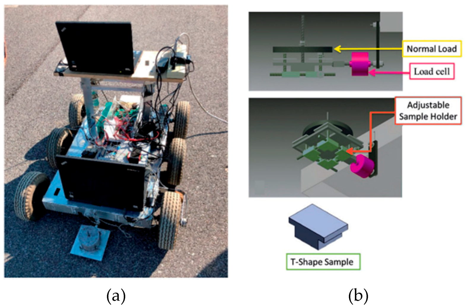
The FT designed and developed at the Centre for Tire Research (CenTiRe), a consortium of tyre and tyre-related industry members with two word-class universities (Virginia Tech and the University of Akron), belongs to this type of tester. This innovative device is an unmanned ground vehicle [
67]. The robot shown in
Figure 20, aims to reproduce all relevant tyre testing conditions on any surface and in both indoor and outdoor experiments.
The device consists in a chassis with six wheels and an assembly of all the essential parts of the device, in which, four of these wheels are driven by a brushed permanent magnet DC motors, coupled directly to the wheels’ shafts, and the other two are nondriven wheels. Two encoders are used to measure the rotational velocity of the wheels, one fixed to the driven wheel the other to the undriven wheel, so that the slip of the wheels can be calculated. Attached to the chassis a dragging arm holds and pulls the sample holder attached in series at load cell. The sample holder is built to fit a T-type sample with different size in the range of 25.4 × 25.4 mm2 to 50.8 × 50.8 mm2.
The main technical specifications are summarized in
Table 10.
The six-wheel small ground robot was developed to study friction and wear of a tread block sample on different surfaces and under different operating conditions. Emami et al. [
67] showed the results of an experimental investigation conducted on a styrene-butadiene rubber (SBR) sample sliding on an asphalt track. The experimental results were conducted outdoor on a clean asphalt track at an outside temperature of 24 °C. The SBR sample used has dimension equal to 25.4 × 25.4 mm
2 and it is loaded with a weight of about 4.5 kg which corresponds to an equivalent pressure between the sample and the road of 81 kPa.
Although the robot was designed to perform measurements on field, it also allows indoor measurements, but these would require very large spaces specially if high speeds are to be achieved. The main limitation of this equipment consists of a particularly small normal load allowed.
Another type of on field FT was developed at the department of the “Forschungsgesellschaft Kraftfahrwesen mbH Aachen (fka) and the Institut für Kraftfahrzeuge (ika)” of RWTH Aachen University. The FT, called LiRep [
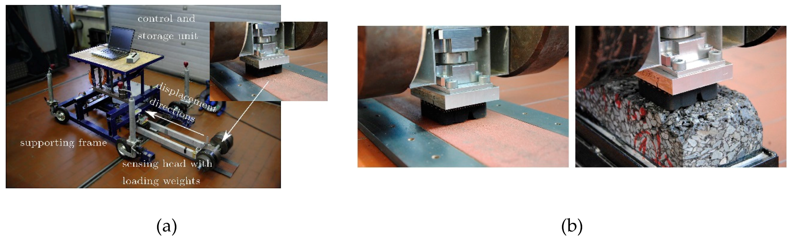
69], is a portable device developed to study friction and wear of a tread block sample on real road surfaces under different operating conditions. The device, shown in
Figure 21, consists of a four-wheeled frame to facilitate transport, therefore these wheels can be easily lifted or removed for performing the tests. The core of the device is a ball screw linear axis driven by a servo motor, that drags a “sensing head” (carriage/sledge) on which the tread-block sample, 3-axis force transducer and the loading weights are mounted. The “sensing-head” allows to install samples of a maximum size of 60 × 60 mm
2, and to add a calibrated weight up to 60 kg. Depending on the contact surface of the sample, these weights correspond to an equivalent pressure between the sample and the road up to 3.5 bar. All data acquisition system, cables and the control unit are located on the chassis. Furthermore, the test area can be covered with a climate chamber to study the effect of temperature on the friction coefficient. The main technical specifications are summarized in
Table 11.
Compared to other FT shown in this category, the main difference is that this device is not a mobile device but rather is attached to the floor, so in this case, it is easier to carry out laboratory tests since the speed and length of the sliding are not linked to the movement of the device.
5. Other Types
This section describes the FTs that not have a common contact mechanism or the same type of movement, for this reason they are classified as “others”.
5.1. Pin on Disk Tribometers
The pin on disk (PoD) configuration is one of the most popular devices used to study the friction and wear. Introduced by the ASTM standards G133 [
71] and G99 [
72] for wear and erosion tests, both these devices are wide used also to study materials like tyre rubber.
Pin on disk (PoD) tribometers, in general, are designed and constructed to study the complex friction phenomena in many engineering applications such as railway wheels, automotive and aircraft brake systems, clutches, bearings, mechanical joints, tyre and biomedical materials. Conventional PoD machines provide a normal contact load between a stationary pin and a revolving disk and measure the resulting frictional force to evaluate the coefficient of friction [
73,
74,
75,
76]. PoD tests can use different contact geometries:
point contact using a ball;
flat contact, often performed using a cylinder;
line contact performed adopting a cylinder aligned in a line contact, which reduces contact pressures a bit and increases the tested areas, but still represent a non-conformal contact and are easier to align than flat contacts.
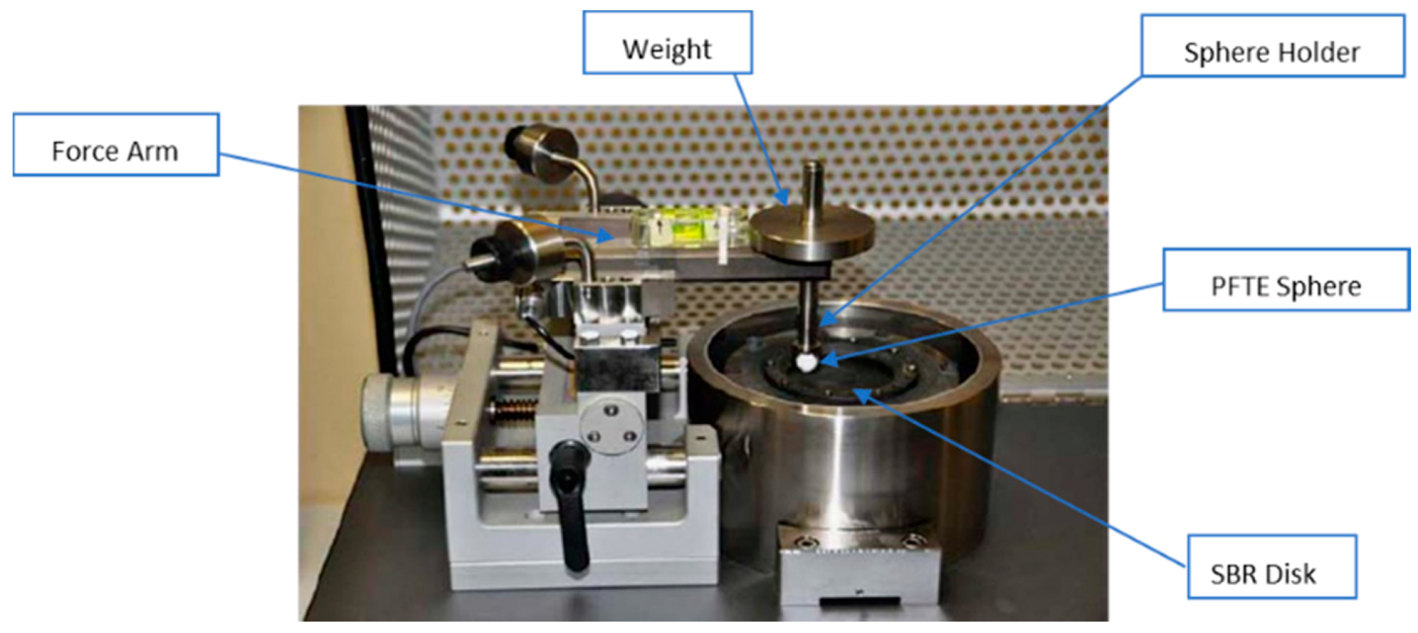
An example of the above equipment is reported in the studies of Carbone et al. [
77], in which the authors have investigated the friction properties of styrene-butadiene rubber (SBR) copolymer, furnished by Pirelli Tyre, by means a ball-on-disk configuration. The friction measurement has been carried out using the CSM Instruments Tribometer available at the Tribology Lab at the Department of Mechanical and Industrial Engineering (Politecnico di Bari, Bari, Italy). The device, shown in
Figure 22, is composed by a rotating SBR disk in contact with a sphere made in polytetrafluoroethylene (PFTE) fixed to the holder and unable to rotate.
The sphere is mounted on a stiff lever, designed as a frictionless force transducer, and is loaded onto the test sample by applying calibrated weights so as to allow adjustment of the normal force in the range 0–10 N. The friction coefficient is determined during the test by measuring the deflection of the highly linear and precise elastic arm, with a resolution of 5 mN while wear coefficients for the ball and disk materials are calculated from the volume of material lost during the test. The instrument allows one to control the velocity of the disk and the radial position of the ball.
The main technical specifications are shown in a
Table 12.
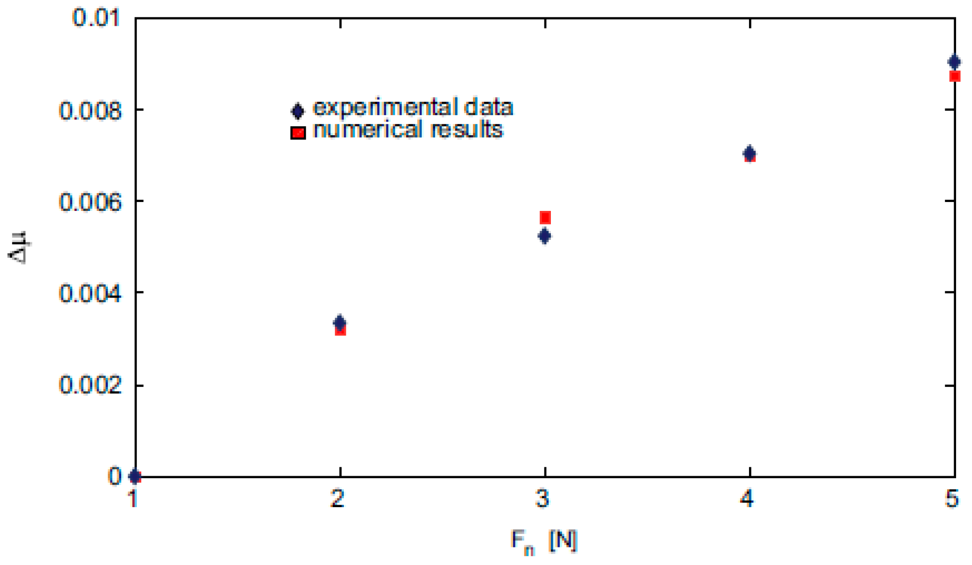
With the aim to investigate the viscoelastic contribution to friction, the authors chose a PFTE sphere to reduce friction and wear between the SBR disk and the sphere. The tests were conducted at the sliding velocity of 6 mm/s and for different normal loads.
Figure 23 shows the comparison between experimental and numeric increase Δμ of the friction coefficient μ as the normal load is increased from 1 N to 5 N.
This device is also designed to study friction and wear behaviour, since it allows one to vary the interfacial friction by replacing test spheres characterized by different roughness. The device allows measurement of friction in a small normal load range, and for this reason and also for the small contact surface, the device is not able to simulate the tyre/road contact conditions.
5.2. Dynamic Friction Tester
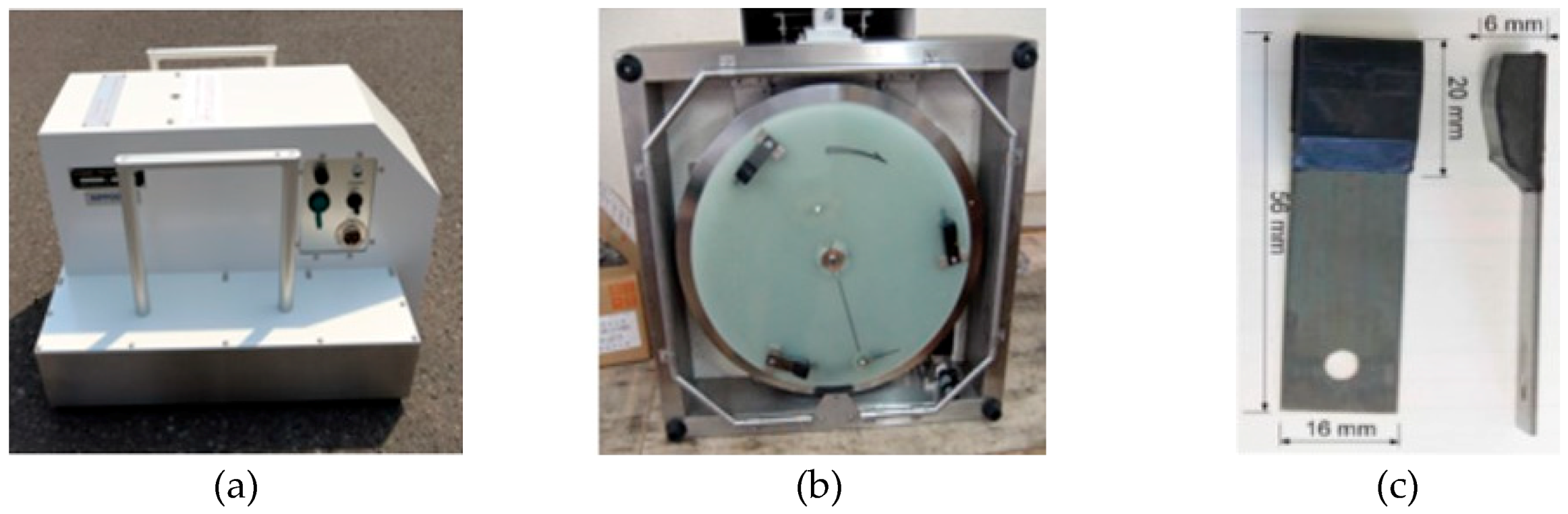
The Dynamic Friction Tester, shortly called DFT, was born like an on-field tester to characterize the paved surface frictional properties and shows a layout conceptually similar to the PoD tribometer. The DFT is equipped with a rotating disc with three connected rubber sample and does not have the fixed part (road surface) since this tester is usually used for friction measurements on the field, but in any case, as shown by a study conducted by Do et al. [
78], the device allows laboratory measurements. This device designed and manufactured in Japan by the Nippo Sangyo Co., Ltd. has being used widely not only in Japan but also in the EU, the United States and many other countries by government agencies, construction companies, independent consulting companies, automotive manufacturers, tyre manufacturers, research institutions and universities among many other organizations [
79]. In EU the leading user of this device is the “Institut Français des Sciences et Technologies des Transports, de l’Aménagement et des Réseaux (IFSTTAR)”. Also, DFT has been chosen as the standard reference by IFI (International Friction Index) ASTM international Standards [
80]. The DFT is reported in the ASTM G115 in the “vehicle pavement system” and the standard test procedure used in the United States can be found in the ASTM E-1911 standard [
81]. The device, shown in
Figure 24, looks like a box where the bottom side has three rubber sliders mounted on the lower surface of a disk that rotates with its plane parallel to the test surface. In the upper side there are the DC electric motor and the control unit.
The main technical specifications are shown in a
Table 13.
As mentioned, the DFT is commonly used for degeminating the road surface frictional properties, in several states in the world. A detailed analysis of the relevant aspects including the experimental results of pavement friction studies, using the DFT, is given by Rado et al. [
83], and Kane et al. [
82,
84]. In the study conducted by Kane et al. [
82] the results of the friction coefficient measurements conducted using the DFT in wet condition are presented, with the goal to develop and validate by means of the DFT a dynamic frictional contact model. During the measurement, the disk is accelerated to reach the target speed, after which, prior to reaching the desired speed, the water is applied and maintained during the entire measurement process through an irrigation system of the device. Once the set speed of the rubber pads is reached, the motor is turned off and the disk with the measuring pads is lowered in contact with the surface with a constant normal load. Each pad is loaded at 11.8 N, chosen due to the weight of the device and the rigidity of the pad holders. The speed of the pads decreases until it stops completely due to the friction generated between the pads and the contact surface, recorded during the deceleration phase from the set speed up to the stop.
The main advantages in the use of the DFT lies in the possibility to operate both indoor and outdoor, in the ease of use and in the possibility of making measurements in a wide range of speeds. The main drawback associated with the use of a commercial machine such as the DFT lays in the fact that it is not possible to study the friction coefficient of tyre tread compounds or to use tread blocks obtained from a tyre, because the friction pads are provided by the manufacturer. In addition, the DFT does not allow to vary the normal load on the sample.
5.3. British Pendulum Test Rig
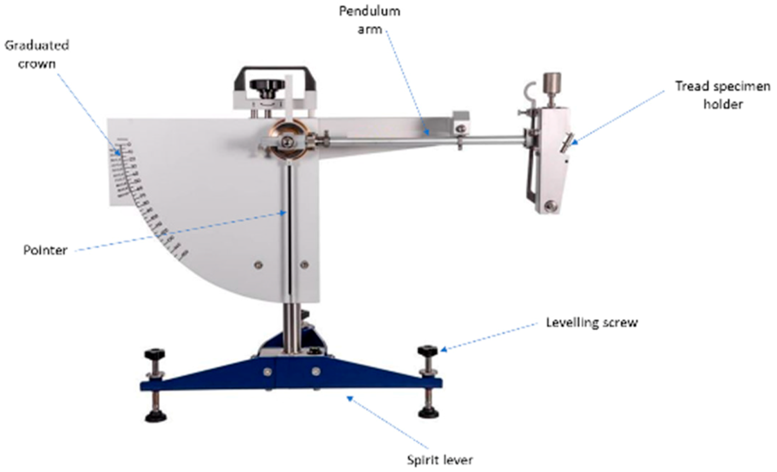
The last device reported in this review is the British Pendulum (BP), widely accepted as a device for both field and laboratory friction testing. The BP test is described in ASTM E303 [
85] as a laboratory testing method to find the skid resistance of pavement surface. It is a low-speed (<10 km/h) test which is related to surface micro-texture of road surface. A typical commercial device is shown in
Figure 25, with its main components. In many researches, BP is used to perform the asphalt characterization [
86,
87], while this review is focused on the devices used to study the interactions between a tread block sample and the road surface.
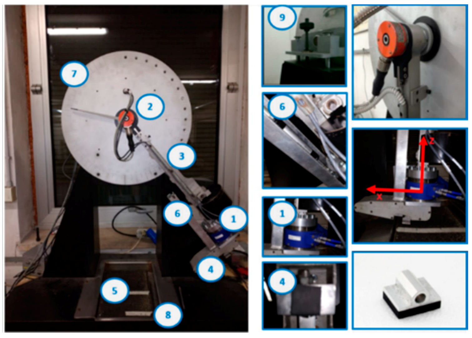
Ciaravola et al. [
88], performed an experimental investigation of contact between tyre tread and rough surfaces by means an evolved version of a standard BP, developed starting from a BP at the Technical Centre Europe Bridgestone and customized at Department of Industrial Engineering, University of Naples Federico II (Naples, Italy). Later, Arricale et al. [
89] performed an experimental investigation on tyre/road friction, between a tread block and real asphalt specimens by means an improved version of the British Pendulum developed by the UniNa Vehicle Dynamic Research Group, also called BP-EVO. The device showed in
Figure 26, conserves the main components of the classic pendulum and is also equipped with a series of sensors allowing to further enrich the measurement dataset.
In detail the BP-EVO is composed by:
an oscillating arm
an encoder to measure the angular speed of the arm
a tri-axial load cell, interposed between the rubber sample and the arm to measure the normal and tangential force
a rubber specimen cut from a tyre tread
a tank to host a road specimen
a road specimen
a pre-loading spring to vary the contact pressure at tyre/road interface
a graduate crown located on the rigid frame of the device, in order to set the drop height, on which the sliding speed depends
a levelling screw to set the height of the oscillating arm from the road specimen
The main technical specifications are showed in
Table 14.
The initial temperature of the tread sample can be varied up to 120 °C by means of an industrial heat gun and measured by an infrared pyrometer. The contact pressure can be varied using different springs. The BP, compared to the testers shown in this review, is certainly the easiest to use and, despite its simple layout, it offers the possibility to be employed in both dry and wet conditions adopting real asphalt and tread samples as a counter face. Since the pendulum is not driven by a motor, the sliding speed depends on the drop height; therefore, it is not possible making measurements in a wide range of sliding speeds. In addition, it should be noted that the range of sliding speeds may vary depending on the characteristics of the tread and the surface. For example, working with rough surfaces and tyres with high performance in terms of friction value, it is impossible to perform test at particularly low sliding speed. The reason is that, at low speed, the sample is stopped when come in contact with the surface, not allowing the friction measurement.
6. Summary and Conclusions
In this review, the studies and the developments carried out with the aim to test and analyse frictional and wear behaviour of viscoelastic materials, and of tyres tread in particular, were examined by comparing the different working principles of different so-called friction testers, with an in-depth focus on a selection of them, representative of each category.
In the authors’ research activity on tyre analysis and friction modelling, the need of a wide overview of the state of the art in tribological testing on viscoelastic materials was experienced. Due to the lack of such kind of information, the aim of the review is to resume devices and methodologies developed in the far and recent past, in order to give suggestions and ideas to who could be interested to build a friction testing bench or to evaluate the optimal methodology to get data concerning interaction phenomena between a rigid and a viscoelastic material.
It has been found that the main variables affecting tyre friction in local contact are sliding speed, contact pressure, tread temperature, road (or in general counter-surface) roughness and compound viscoelastic characteristics. Consequently, most of the developed friction test benches allow to the user to vary such variables in a range due to space and to technological constraints.
Friction coefficient is expressed as the ratio between the tangential and the normal load acting on the tested specimen, and for this reason the rigs are usually equipped with load cells and with control systems that guarantee stability and precision in the test setup and in the conduction of the experiments.
A key obstacle encountered in the tyre friction testing regards the possibility to vary single working conditions, keeping the others constant. The difficulty is due to the mutual and deep interconnections among the phenomena arising at tyre/road contact, and in many of the described applications the solution has been fund involving very small variations in the working conditions. On the other hand, real tyre working conditions are characterized by significant values of speed and pressure, not easily reachable and controllable by laboratory benches. For this reason, “on field” friction testers have been developed, able to observe real contact conditions, despite the lower level of repeatability and precision of the measurements linked to the noise and the random nature of the asphalt profile.
The variation of contact pressure in the indoor benches is usually controlled by the actuation of controlled pneumatic systems, while the speed management is highly linked to the motion principle of the bench itself (linear, rotational, etc…).
Some of the illustrated devices, moreover, are installed in a climate chamber that allows a reliable control of temperature, highly affecting the tread polymers viscoelastic behaviour. Such solution improves the repeatability of the measurements and gives the opportunity to test the specimens also in uncommon or hardly reachable environmental conditions, but increases significantly the cost and the volume of the experimental setup.
Finally, some friction testers have been developed re-adapting systems conceived for different scopes (like pin on disk benches, often adopted for hardness and wear measurements in metal-metal sliding contact), substituting some elements with specimens of rubber to be tested.
As a final summary, a table of FT features (
Table 15) has been developed, with the aim to provide a global overview of the described benches, each with its peculiar characteristics and advantages/disadvantages.
In conclusion, friction, and in particular friction between a viscoelastic material and a randomly rough and rigid surface, still represents a field in which significant efforts in terms of research and testing are daily spent. Each of the benches reported and analysed is useful to study some specific aspect of very complex phenomena, but it seems that an ultimate technological solution, able to reproduce the global effects involved in tyre/road sliding contact in a fully satisfying way, has not been developed yet. The improvements in control systems and in the accuracy of the measurement devices are leading to increasingly evolved benches, able to lead researchers and industries, interested in a fundamental topic for mobility, road safety and polymers science, towards a deeper understanding of contact mechanics.


