Article

Effect of Graphene Addition in Cutting Fluids Applied by MQL in End Milling of AISI 1045 Steel

by
Vitor Baldin
1,
Leonardo Rosa Ribeiro da Silva
1,2,*,
Celso Ferraz Houck
3,
Rogério Valentim Gelamo
4 and
Álisson Rocha Machado
1,2
1
Graduate Program in Mechanical Engineering, Pontifícia Universidade Católica do Paraná—PUC-PR, R. Imaculada Conceição, 1155, Bairro Prado Velho, Curitiba 80215-901, PR, Brazil
2
School of Mechanical Engineering, Federal University of Uberlandia, Av. João Naves de Ávila, 2121, Bloco 1M, Uberlândia 38400-902, MG, Brazil
3
Specialmix Industrial Ltd.a, R. Antônio Lacerda Braga, 341, Cidade Industrial de Curitiba, Curitiba 81170-240, PR, Brazil
4
Institute of Techonogical and Exact Sciences, Federal University of Triângulo Mineiro, Av. Doutor Randolfo Borges Júnior, Uberaba 38064-100, MG, Brazil
*
Author to whom correspondence should be addressed.
Submission received: 22 May 2021 / Revised: 5 July 2021 / Accepted: 12 July 2021 / Published: 19 July 2021
(This article belongs to the Special Issue Application of Solid Lubricants in Metal Processing)

Abstract

:
The cutting fluids applied to the machining processes by the MQL process aim to reduce the machining temperatures and tool wear as well as improve the surface and dimensional finishing of the parts. To increase the efficiency of these fluids, graphene lubricating platelets are added. This work investigated the performance of three different cutting fluids with graphene sheets added and applied via MQL, considering the tool life, wear, and wear mechanisms acting on TiAlN-coated cemented carbide cutting tools in the end milling of AISI 1045 steel. We evaluated two vegetable- (MQL15 and LB1000) and one mineral-based (MQL14) neat oils and the same fluids with the addition of 0.05 and 0.1%wt graphene nanoplatelets. Dry cuts were also performed and investigated for comparison. The experiments were conducted under fixed cutting conditions (vc = 250 m/min, fz = 0.14 mm/tooth, ap = 1 mm, and ae = 20 mm). The end-of-tool-life criterion followed the guidelines of ISO 8688-1 (1989). To analyze the results, ANOVA and Tukey’s test were applied. The addition of graphene sheets in the vegetable-based cutting fluids effectively increased the lubricating properties, partially reducing the wear mechanisms acting on the tools. In addition, there was a predominance of thermal fatigue cracks and mechanical cracks as well as adhesive and abrasive wear mechanisms on the tools used in the cutting with the MQL15 and MQL14 fluids, indicating greater cyclical fluctuations in temperature and surface stresses.

1. Introduction

In all machining processes, there is heat generation during material removal. In some specific processes, the amount of heat generated is so significant that it can result in thermal damage to the machined component. Therefore, in most operations, cutting fluid is used to circumvent this challenge. Cutting fluids primarily function to cool, lubricate, and remove chips from the cutting zone [1].
In the metal machining industry, the milling process stands out for presenting great versatility and the possibility of producing parts with complex geometric shapes with a high capacity for material removal. The process is characterized by being an interrupted cut, where the cutting tool, composed of several teeth, intermittently removes material from the part. Thus, each cutting edge of the tool undergoes fluctuations in thermal and mechanical loads, which promote cracks and wear on the cutting tools, decreasing their life, and compromising the surface integrity and dimensional accuracy of the component [1].
Wear is the continuous removal of material from the tool caused by tribological phenomena. According to the standard [2], tool wear is a geometric change that occurs gradually on their surfaces through the gradual loss of mass or plastic deformation. Wear arises at the primary and secondary cutting edges, the primary and secondary clearance faces, rake face, and the corner radius of the tool, classified as crater, flank, notch, and corner radius wear. Crater wear appears on the rake face and is characteristic of high-stress levels, high machining temperatures, and chemical affinity between the materials. Flank wear is caused by the friction between the cutting tool’s primary and secondary clearance faces and the machined surface of the material. This friction between the surfaces generates an increase in temperature, which causes wear. Notch wear is generated on the clearance surfaces of the tool (flank face), but it can evolve to the rake face, positioning itself mainly at the end of the depth of cut where the contact between the main cutting edge and the workpiece ends [3]. The wear of the cutting tools can be driven by adhesion, diffusion, abrasion, and oxidation mechanisms, which depend on the cutting parameters, part material, tool material, coating material, and the lubricant/coolant conditions adopted in the machining [4].
Cutting fluids are used to reduce wear on cutting tools while improving surface finish and dimensional control. The high costs of cutting fluids, ecological and legal issues related to the preservation of the environment, and the health of the people involved in machining processes [5,6] contribute to the development of technologies that reduce the amount of fluids used in machining, such as the MQL method [7]. In this method, a mist of fluid is applied to the cutting zone but only the amount needed to promote lubrication [8], which is ensured when the quantity of lubricant is sufficient to lubricate the chip–tool–workpiece interfaces in order to reduce friction and decrease material adherence to the tool [9].
To increase the efficiency of the cutting fluids, lubricating graphene particles are added to the fluids applied via MQL [10,11]. The use of a solid lubricant in the machining operation is one of the most effective strategies to increase the efficiency of sustainable machining systems. The addition of these particles aims to improve the lubricant/coolant properties of the fluids and, consequently, reduce the components of the machining force, cutting temperature, surface roughness, wear, and life of the cutting tools [12]. The addition of graphene increases the lubricating/cooling capacity of the cutting fluids by reducing the friction between the surfaces of the tool part/chip [13]. This reduction in contact decreases forces and temperature fluctuations gradually as the percentage of graphene increases [14,15]. The reduction of friction between the surfaces of the tool part/chip and the reduction of peaks and temperature fluctuations caused by machining with graphene results in reduced wear and damage to the cutting tools. This decrease also depends on the MQL parameters [16] and the proportion of graphene [17].
This work aimed to investigate the tool life, wear, and wear mechanisms acting on TiAlN-coated carbide cutting tools in end milling of AISI 1045 steel with the application of vegetable- and mineral-based neat oils, as well as the same oils with additions of 0.05 and 0.1%wt of graphene nanoplatelets, all applied via MQL.

2. Experimental Procedures

2.1. Characterization of Materials

AISI 1045 steel was used as the workpiece for the milling experiments, and Table 1 shows the chemical elements of AISI 1045 steel. This steel was characterized according to the ASTM E8/E8M standard [18], resulting in an average tensile strength of 868.77 MPa and 13.60% elongation. The steel also had a surface hardness of 262 ± 11.35 HV1, measured according to the ASTM E92-17 standard [19].
Three different neat oil cutting fluids were evaluated, of which two are manufactured by SpecialMix Industrial Ltd.a (Paraná, Brasil), Curitiba-PR, (MQL14 and MQL15), and one manufactured by ITW Chemical Products Ltd.a (Sao Paulo, Brazil), Araras-SP, (LB1000). MQL15 and LB1000 are vegetable-based, and MQL 14 is mineral-based. The main characteristics of the fluids are summarized in Table 2, including their chemical nature. This information was found in the Material Safety Data Sheet (MSDS) prepared according to NBR 14725:2014.
In this work, graphene was mixed with the cutting fluids. Graphene platelets were produced by the mechanical exfoliation of natural graphite, as described in [20]. The dispersion of 0.05 and 0.1%wt of the graphene in the cutting fluids was performed using an ultrasonic bath system until the complete dispersion of the graphene particles in the studied fluid occurred. As no dispersant was used in the nanofluids, the homogenization of the mixture was guaranteed by taking them to a sonicator for 15 min at 40-min intervals to avoid sedimentation of the graphene. However, in preliminary tests no sedimentation of graphene was observed for periods of up to 4 h with the nanofluid at rest. Neat oils were used without the addition of water, just graphene.
Figure 1a,b present the dimensions and geometry of the graphene sheets obtained by the Gwyddion software from the AFM results. In the four profiles measured, the thicknesses of the graphene platelets were approximately 8.62, 7.02, 7.64, and 10.57 nm. These results are similar to those found in [21,22]. Graphene sheets were also analyzed using a transmission electron microscope (TEM), JEOL JEM 1200EX-II. Figure 1a presents an image of a graphene particle with multiple layers (or sheets) identified via electron diffraction (Figure 1c), where the external hexagonal (arrangement of the carbon atoms) had an intensity equal to or greater than the internal hexagonal. These results are consistent with other studies [13,23,24,25] and prove that the graphene particles added to the fluids were composed of mono and multilayers. The size distribution of graphene sheets followed the dimensions shown in Figure 1a.

2.2. End Milling Tests

The milling process was carried out in a CNC machine center, Arrow 500, manufactured by Cincinnati Milacron Mount Orab-OH, Batavia, OH, United States (Figure 2b). Interchangeable carbide tools (ISO code AOMT123608 PEER M) were used, manufactured by Mitsubishi Materials (Chiyoda-ku, Japan), Bela Vista-SP, with TiAlN coating (manufacturer’s reference: VP15TF) and a type M chip breaker, recommended for machining carbon steel in general. Figure 2c illustrates the geometric and dimensional aspects of the tool insert and the 25 mm milling cutter; Mitsubishi Materials, Bela Vista-SP, has also manufactured this shank with a capacity for three inserts (ISO 13399 designation and manufacturer’s description APX3000R253SA25SA).
The following constant cutting condition was defined for the milling experiments: vc 250 m/min, feed rate of 0.14 mm/tooth, axial depth of cut (ap) of 1 mm, and radial depth of cut (ae) 20 mm. The lubrication–cooling conditions tested were the external application of neat oils via MQL at 45 mL/h by two nozzles 180° apart (Figure 2a). The oils were also mixed with graphene platelets at the proportions of 0.05 and 0.1%wt, and the dry cut was also tested for comparison. The tests were performed using the up milling cutting strategy, with only one insert fixed to the 25 mm end milling cutter, without compromising the comparative results, according to [26]. Tool wear was periodically monitored at intervals that made it possible to generate the wear vs. time curves. The process was interrupted, the tool removed from the holder and submitted for analysis under the Zeiss Stereo Microscope Discovery V12 to measure and verify wear evolution. As noted in Figure 3, it was necessary to outline the corner radius as one of the regions monitored. This separation followed the approximate and standardized distance of 601 µm on both sides of the tool, as the junction point between the edges and the corner radius.
The end-of-tool-life criterion was determined after pre-tests that indicated the predominance of corner wear in the flank face. The tests were interrupted when the flank corner wear VBC reached 0.3 mm. Only the crater’s width (KB) was measured for the evaluation of crater wear.
The wear, damage, and wear mechanisms of the cutting tools were analyzed via scanning electron microscopy (SEM) and the dispersive energy spectroscopy (EDS) technique using the Vega3, Tescan, and Oxford INCAx-act equipped with the VegaTC and AZtec-P2 software.
For greater reliability of the results, three replicas were performed for each cutting condition, where an analysis of variance with a 95% reliability index (ANOVA) and Tukey’s test were applied to identify the cutting conditions that showed significant variations between pairs.

3. Results

3.1. Tool Life and Surface Roughness

This section presents the results related to the wear of the cutting tools and the evolution of surface roughness over their lifetime. To simplify the graphical representation, the name of the cutting fluid plus 0.05G (graphite) was used as nomenclature for the proportion of 0.05%wt. graphene and 0.1G for the proportion of 0.1%wt.
Figure 4, Figure 5 and Figure 6 illustrate the results of the evolution of tool wear and Ra of the cutting tools for the dry, neat oils MQL, and neat oils with graphene addition MQL. The surface roughness in the dry condition categorically reflected the tool’s wear due to scarring on the material’s surface. The increase in the tools’ lives for cutting conditions with MQL as compared to dry cutting was noticeable, highlighting, in this case, the lubricating and cooling capacity of MQL application. In experiments with pure MQL15 fluid, wear rates developed rapidly with a gradual increase in Ra, highlighting, in this case, the cascading effect between wear and roughness.
As suggested by Figure 4a and Figure 5a, graphene additions in the vegetable-based fluids (MQL15 and LB1000) resulted in instability and lower Ra values, even though there was no statistically reduced wear in the first 7 min of machining, as was the case with the MQL15 and LB1000 fluids. However, an increase in the tool life of the tools was found with the addition of the graphene platelets; in these cases, the wear rates were lower.
The increase in the tool life with vegetable-based fluids was because graphene replaces lubricant layers, reducing adhesion and friction of the forming surfaces [27]. According to Sayuti et al. [28], the increase in graphene concentration improves the degree of chemical interaction between the nanoparticles and the newly formed surface, increasing, in this case, the protective film between the tribological pairs, consequently increasing the surface quality. The lubricating benefits of using graphene in vegetable-based fluids have justified their use in machining applications, as the solid lubricants reduce the friction coefficients and wear of cutting tools [29].
In the mineral-based fluid MQL14, graphene nanoparticles reduced tool life (Figure 6); even so, cutting with pure MQL14 and MQL14-0.05G fluids resulted in better results than dry cutting, with tool life being 327% and 259% higher than dry cutting.
As shown in Table 3, elaborated with the data of the machining times presented in Figure 4, Figure 5 and Figure 6, the tool lives in MQL milling showed a significant increase compared to dry cutting, a result already expected. However, a comparison of the performance of the cutting fluids shows that the use of plant-based fluids with graphene addition caused an increase in the tool life. An increase of approximately 17% for LB1000-0.05G fluid and 36% for LB1000-0.1G fluid compared to the neat LB1000 fluid were observed. In MQL15 fluid, the increases were 4% and 11% compared to the neat MQL15. On the other hand, for the mineral-based MQL14 fluid, the addition of graphene reduced the tool life by approximately 16% with 0.05%wt and 30% with 0.1%wt graphene as compared to neat MQL14. With ANOVA, it was possible to statistically prove the increase in the life of the cutting tools with the vegetable-based fluids (MQL15) and the reduction with the mineral-based fluid (MQL14).

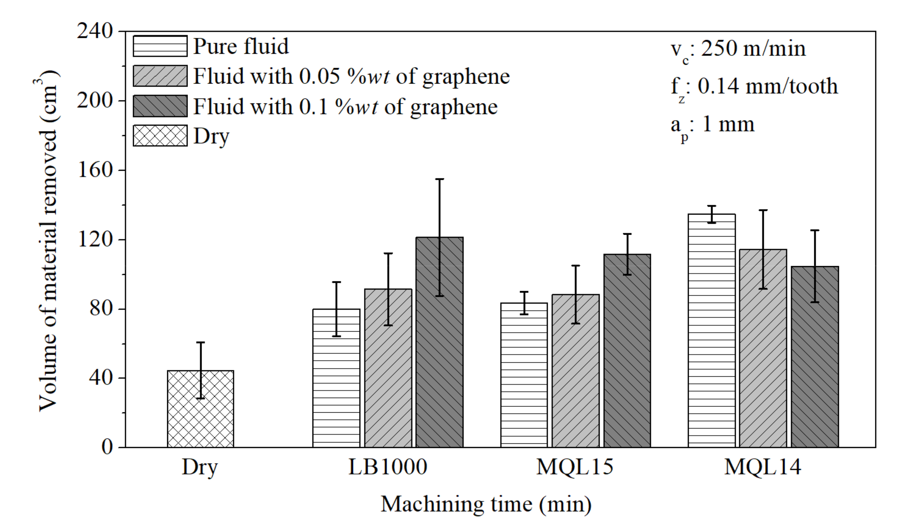
3.2. Volume of Material Removed

Another way to present the tool performance results is using the volume of material removed (VMR). When using a tool for just a few minutes, no one knows the amount of material removed (or the production efficiency) unless calculations are made considering the cutting conditions employed. Since machine shops are mainly interested in production efficiency, the tool lives according to the VMR are presented in Figure 7. It can be observed that the addition of graphene increased the volume of material removed for vegetable-based fluids (LB1000 and MQL15), being more effective at the highest concentration (0.1%wt). The VMR decreased with the mineral-based fluid (MQL14), being more damaging also in the highest concentration. These results follow the trends presented in Figure 4, Figure 5 and Figure 6 since the VMR is directly related to the tool lives.
With the help of ANOVA (Table 4), it was possible to identify the differences in the VMR when cutting with different lubricating–cooling conditions, and these differences were validated in peer comparisons (Tukey’s test) with an index of 95% reliability, where it was found that the VMR in dry milling was statistically lower compared to milling with fluids LB1000-0.1G, MQL15-0.1G, MQL14, MQL14-0.05G, and MQL14-0.1G.

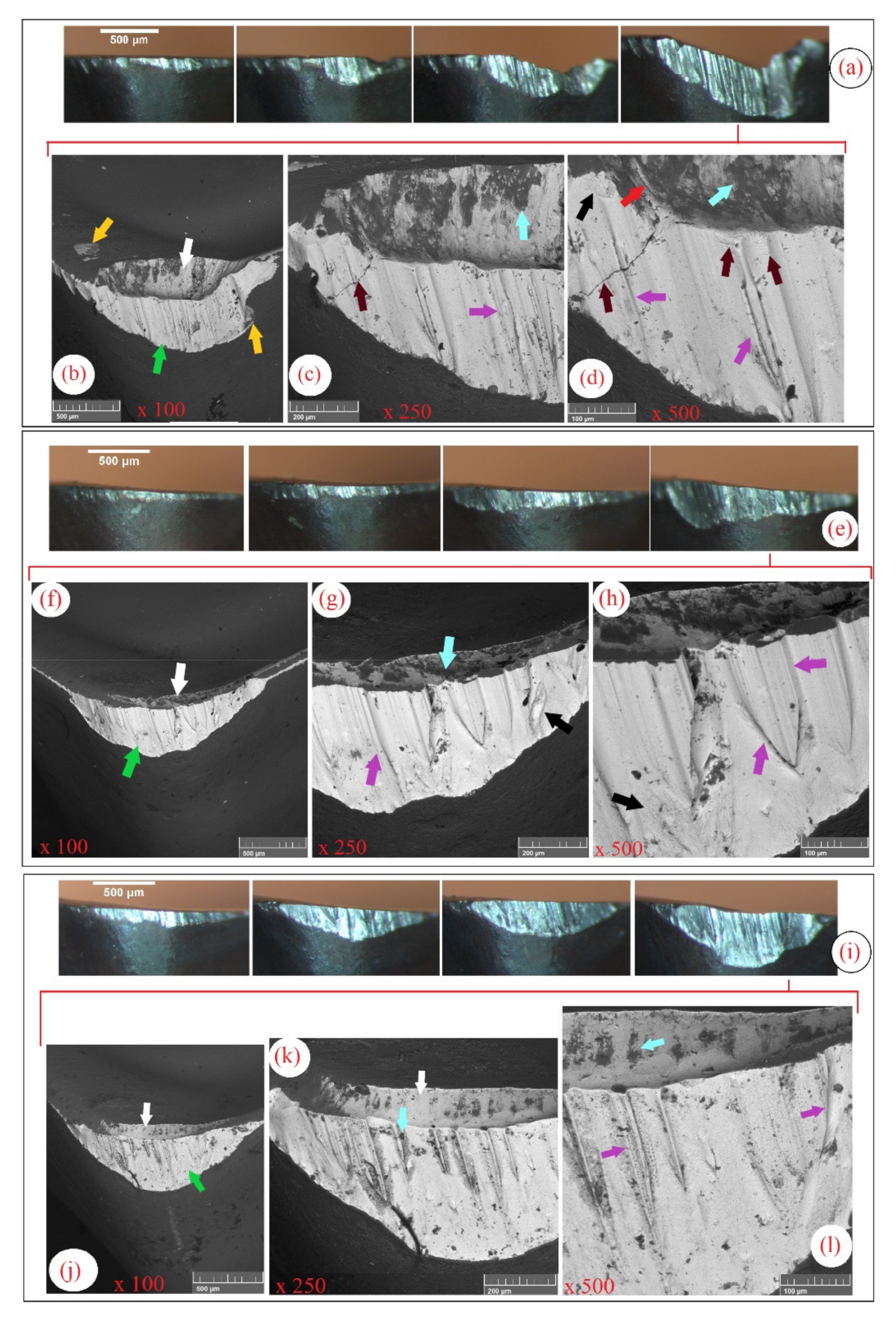
3.3. Tool Wear and Wear Mechanisms

This section presents the wear, damage, and wear mechanisms of the cutting tools for the experimental work conditions. Optical (stereomicroscope) and scanning electron microscopy (SEM) were used in the analyses. Arrows with different colors are used to identify the different damages and wear mechanisms in the figures. The SEM photos presented also used 100, 250, and 500× magnifications.
Figure 8a shows a sequence of images taken with a stereomicroscope showing the rapid evolution of wear on a tool subjected to dry cutting. According to Figure 8b, the tool suffered wear on the main, secondary, and corner flank surfaces (indicated by the green arrow), crater wear (indicated by the white arrow), and chipping (indicated by the yellow arrow). Figure 8c,d highlight thermal cracks (red arrows), material adhered to the tool (light blue arrows), removal of particles from the tool surface (a rough aspect of the worn surface) indicating the adhesive wear mechanism (black arrow), and parallel microgrooves on the flank face indicating the abrasive wear mechanism (purple arrows). These indicate that cracks due to thermal fatigue, abrasion, and adhesion in the dry cut are the wear mechanisms responsible for the rapid deterioration of the tool cutting edge and short tool life.
Figure 9 illustrates the wear patterns on the tools used to cut the AISI 1045 steel with the LB1000 fluids. Figure 9a,e,i are optical images, while the others are SEM images. In the SEM images, the damages present in the tools are identified by arrows as follows: flank and corner wear (green arrows), crater wear (white arrows), microchipping (yellow arrows), abrasive wear on the rake and clearance surfaces (purple arrows) (Figure 9b), mechanical cracks (brown arrows), and thermal cracks (red arrow).
Mechanical and thermal cracks did not appear in the cutting conditions with the LB1000 fluids with graphene additions, indicating a decrease in cyclic temperature fluctuations and surface stresses in the tools because of the addition of the solid lubricant, mainly in the proportion of 0.1%wt as seen in Figure 9. However, graphene could not avoid the appearance of parallel microgrooves developed in the direction of the material flow. These microgrooves are caused by the detachment of hard particles from the coating and tool (adhesive wear), and it was observed in all tests with the LB1000 oil (Figure 9). In addition, graphene platelets visibly reduced crater wear when machining with LB1000 fluid.
Figure 10 illustrates the evolution of the wear on the tools used in the tests with the MQL15 fluids. As shown in Figure 10b,f,j, the flank and corner wear (green arrow) are predominant in the cutting conditions with MQL15 fluids. However, many mechanical (brown arrows) and thermal (red arrows) cracks as well as microchipping (yellow arrows) stand out as critical failure modes. In addition to cracks, the parallel grooves (purple arrows) present on the clearance surfaces in all cutting conditions (Figure 10) indicate the predominance of the abrasive wear mechanism (purple arrows). Also observed in the images were adhered work material (light blue arrows), rough and worn surfaces indicating the presence of adhesive wear mechanism (black arrows), and the minor crater wear on the tools used with the MQL15 fluids.
Figure 11 illustrates the evolution of the wear on the tools used in the milling tests with the MQL14 fluids. Flank and corner wear (green arrows) are predominant in cutting with the MQL14 fluids. Mechanical cracks (brown arrows) and thermal cracks (red arrows) are present in the tests with fluids with graphene additions, where the association of mechanical cracks with the adhesive wear mechanism caused the detachment of small fragments of the tool or spalling (red circles). It was also observed in the images adhered work material (light blue arrows) and rough, worn surfaces, indicating the presence of the adhesive wear mechanism (black arrows). Abrasive wear on tools used in the tests with the mineral-based oil MQL14 occurred due to a more significant agglomeration of graphene sheets, forming particles with larger dimensions. In this case, as mentioned by AZMAN et al. [30], the larger graphene particles act between the tribological pairs with an increase in COF, surface deformation, and consequently abrasive wear due to the action of hard particles detached from the tool and part. In vegetable-based fluids, the graphene sheets form a smooth and compact friction film between the surfaces, reducing friction and wear on the tool surfaces [31].
During the SEM analyses of the wear on the cutting tools, energy dispersive spectrometry analyses were also performed after cleaning the worn cutting edges with 3% Nital for approximately 15 min. The EDS results revealed the tungsten carbide (WC), Co as the binding material, Ti and Al nitrides of the coating, and Fe, Mn, and C composition of AISI 1045 steel.

4. Conclusions

The results obtained in the experiments allow the following conclusions to be drawn:
  • Dry machining proved to be in general the most critical machining condition, where the performance of the wear mechanisms were more intense, resulting in shorter tool life;
  • In all cutting conditions, the removal of the coating and the appearance of the substrate by the action of the temperature and an adhesive wear mechanism predominated, which damaged the cutting edges and the rake surfaces by abrasion of hard particles detached from the tool;
  • The presence of thermal and mechanical fatigue cracks on the tools used in the tests with the MQL15 and MQL14 fluids indicates more significant cyclical fluctuations in temperature and surface stresses in the cutting tools, where the probability of the appearance and multiplication of cracks increases. This is indicative of a possible greater cooling capacity of the MQL15 and MQL14 fluids compared to the LB1000 fluid;
  • The MQL14 mineral-based neat oil provided the most extended tool life among the tested lubricating–cooling conditions; however, the MQL14 fluid with the addition of graphene platelets, regardless of the concentration, accelerated the wear mechanisms, consequently reducing the tool lives. In this case, the graphene platelets acted as foreign bodies between the tool and the workpiece/chip, and together with the release of hard particles from the coating and substrate of the tool intensified the abrasive wear mechanism;
  • The addition of graphene sheets in the vegetable-based cutting fluids effectively increased the lubricating properties, partially reducing the wear mechanisms acting on the tools, mainly in the higher proportion of 0.1%wt.

Author Contributions

Conceptualization, Á.R.M. and C.F.H.; methodology, V.B. and Á.R.M.; validation, V.B. and L.R.R.d.S.; formal analysis, V.B. and L.R.R.d.S.; resources, C.F.H., R.V.G.; data curation, V.B. and L.R.R.d.S.; writing—original draft preparation, V.B. and L.R.R.d.S.; writing—review and editing, V.B. and L.R.R.d.S. All authors have read and agreed to the published version of the manuscript.

Funding

This study was financed in part by the Coordenação de Aperfeiçoamento de Pessoal de Nível Superior—Brasil (CAPES)—Finance Code 001 and CNPq.

Data Availability Statement

Not applicable.

Acknowledgments

The authors would also like to thank the Pontifical Catholic University of Paraná (PUCPR) and the Federal University of Uberlândia, Brazil, for their technical support.

Conflicts of Interest

The authors declare no conflict of interest.

References

  1. Da Silva, R.; Vieira, J.; Cardoso, R.; Carvalho, H.; Costa, E.; Machado, A.; De Ávila, R. Tool wear analysis in milling of medium carbon steel with coated cemented carbide inserts using different machining lubrication/cooling systems. Wear 2011, 271, 2459–2465. [Google Scholar] [CrossRef]
  2. ISO 8688-1, Tool Life Test in Milling—Part 1: Face Milling; International Organization for Standardization: Geneva, Switzerland, 1989; p. 32.
  3. Trent, E.M.; Wright, P.K. Metal Cutting; Elsevier: Amsterdam, The Netherlands, 2000. [Google Scholar]
  4. Waydande, P.; Ambhore, N.; Chinchanikar, S. A Review on Tool Wear Monitoring System. J. Mech. Eng. Autom. 2016, 6, 49–53. [Google Scholar] [CrossRef]
  5. Cyprowski, M.; Piotrowska, M.; Żakowska, Z.; Szadkowska-Stańczyk, I. Microbial and Endotoxin Contamination of Water-Soluble Metalworking Fluids. Int. J. Occup. Med. Environ. Health 2007, 20, 365–371. [Google Scholar] [CrossRef] [Green Version]
  6. Mannekote, J.K.; Kailas, S.V.; Venkatesh, K.; Kathyayini, N. Environmentally friendly functional fluids from renewable and sustainable sources-A review. Renew. Sustain. Energy Rev. 2018, 81, 1787–1801. [Google Scholar] [CrossRef]
  7. Gilbert, Y.; Veillette, M.; Duchaine, C. Metalworking fluids biodiversity characterization. J. Appl. Microbiol. 2010, 108, 437–449. [Google Scholar] [CrossRef]
  8. Dhar, N.; Ahmed, M.; Islam, S. An experimental investigation on effect of minimum quantity lubrication in machining AISI 1040 steel. Int. J. Mach. Tools Manuf. 2007, 47, 748–753. [Google Scholar] [CrossRef]
  9. Machado, A.; Wallbank, J. The effect of extremely low lubricant volumes in machining. Wear 1997, 210, 76–82. [Google Scholar] [CrossRef]
  10. Uysal, M.; Akbulut, H.; Tokur, M.; Algül, H.; Çetinkaya, T. Structural and sliding wear properties of Ag/Graphene/WC hybrid nanocomposites produced by electroless co-deposition. J. Alloy. Compd. 2016, 654, 185–195. [Google Scholar] [CrossRef]
  11. Lv, T.; Huang, S.; Liu, E.; Ma, Y.; Xu, X. Tribological and machining characteristics of an electrostatic minimum quantity lubrication (EMQL) technology using graphene nano-lubricants as cutting fluids. J. Manuf. Process. 2018, 34, 225–237. [Google Scholar] [CrossRef]
  12. Li, M.; Yu, T.; Zhang, R.; Yang, L.; Li, H.; Wang, W. MQL milling of TC4 alloy by dispersing graphene into vegetable oil-based cutting fluid. Int. J. Adv. Manuf. Technol. 2018, 99, 1735–1753. [Google Scholar] [CrossRef]
  13. Samuel, J.; Rafiee, J.; Dhiman, P.; Yu, Z.-Z.; Koratkar, N. Graphene Colloidal Suspensions as High Performance Semi-Synthetic Metal-Working Fluids. J. Phys. Chem. C 2011, 115, 3410–3415. [Google Scholar] [CrossRef]
  14. Park, K.-H.; Ewald, B.; Kwon, P.Y. Effect of Nano-Enhanced Lubricant in Minimum Quantity Lubrication Balling Milling. J. Tribol. 2011, 133, 031803. [Google Scholar] [CrossRef]
  15. Uysal, A. An experimental study on cutting temperature and burr in milling of ferritic stainless steel under MQL using nano graphene reinforced cutting fluid. Adv. Mater. Proc. 2017, 2, 560–563. [Google Scholar] [CrossRef]
  16. De Lacalle, L.N.L.; Angulo, C.; Lamikiz, A.; Sanchez, J.A. Experimental and numerical investigation of the effect of spray cutting fluids in high speed milling. J. Mater. Process. Technol. 2006, 172, 11–15. [Google Scholar] [CrossRef]
  17. Uysal, A. Investigation of flank wear in MQL milling of ferritic stainless steel by using nano graphene reinforced vegetable cutting fluid. Ind. Lubr. Tribol. 2016, 68, 446–451. [Google Scholar] [CrossRef]
  18. ASTM E8/E8M, Standard Test Methods for Tension Testing of Metallic Materials. ASTM Int. 2013. [CrossRef]
  19. ASTM E92-17, Standard Test Methods for Vickers Hardness and Knoop Hardness of Metallic Materials. ASTM Int. 2009, 3128. [CrossRef]
  20. Machuno, L.G.B.; Oliveira, A.R.; Furlan, R.H.; Lima, A.B.; DE Morais, L.C.; Gelamo, R.V. Multilayer Graphene Films Obtained by Dip Coating Technique. Mater. Res. 2015, 18, 775–780. [Google Scholar] [CrossRef] [Green Version]
  21. De Paiva, R.L.; Ruzzi, R.D.S.; De Oliveira, L.R.; Filho, E.P.B.; Neto, L.M.G.; Gelamo, R.V.; Da Silva, R.B. Experimental study of the influence of graphene platelets on the performance of grinding of SAE 52100 steel. Int. J. Adv. Manuf. Technol. 2020, 110, 1–12. [Google Scholar] [CrossRef]
  22. De Oliveira, D.; Da Silva, R.; Gelamo, R. Influence of multilayer graphene platelet concentration dispersed in semi-synthetic oil on the grinding performance of Inconel 718 alloy under various machining conditions. Wear 2019, 426-427, 1371–1383. [Google Scholar] [CrossRef]
  23. Dato, A.; Radmilovic, V.; Lee, Z.; Phillips, J.; Frenklach, M. Substrate-Free Gas-Phase Synthesis of Graphene Sheets. Nano Lett. 2008, 8, 2012–2016. [Google Scholar] [CrossRef]
  24. Ferrari, A.C.; Meyer, J.; Scardaci, V.; Casiraghi, C.; Lazzeri, M.; Mauri, F.; Piscanec, S.; Jiang, D.; Novoselov, K.; Roth, S.; et al. Raman Spectrum of Graphene and Graphene Layers. Phys. Rev. Lett. 2006, 97, 187401. [Google Scholar] [CrossRef] [PubMed] [Green Version]
  25. Hernandez, Y.; Nicolosi, V.; Lotya, M.; Blighe, F.M.; Sun, Z.; De, S.; McGovern, I.T.; Holland, B.; Byrne, M.; Gun’Ko, Y.; et al. High-yield production of graphene by liquid-phase exfoliation of graphite. Nat. Nanotechnol. 2008, 3, 563–568. [Google Scholar] [CrossRef] [Green Version]
  26. Richetti, A.; Machado, Á.R.; Da Silva, M.; Ezugwu, E.; Bonney, J. Influence of the number of inserts for tool life evaluation in face milling of steels. Int. J. Mach. Tools Manuf. 2004, 44, 695–700. [Google Scholar] [CrossRef]
  27. Berman, D.; Erdemir, A.; Sumant, A.V. Graphene: A new emerging lubricant. Mater. Today 2014, 17, 31–42. [Google Scholar] [CrossRef]
  28. Sayuti, M.; Sarhan, A.A.D.; Hamdi, M. An investigation of optimum SiO2 nanolubrication parameters in end milling of aerospace Al6061-T6 alloy. Int. J. Adv. Manuf. Technol. 2012, 67, 833–849. [Google Scholar] [CrossRef]
  29. Sharma, A.K.; Tiwari, A.K.; Dixit, A.R.; Singh, R.K.; Singh, M. Novel uses of alumina/graphene hybrid nanoparticle additives for improved tribological properties of lubricant in turning operation. Tribol. Int. 2018, 119, 99–111. [Google Scholar] [CrossRef]
  30. Azman, S.S.N.; Zulkifli, N.W.M.; Masjuki, H.; Gulzar, M.; Zahid, R. Study of tribological properties of lubricating oil blend added with graphene nanoplatelets. J. Mater. Res. 2016, 31, 1932–1938. [Google Scholar] [CrossRef]
  31. Wang, X.; Li, C.; Zhang, Y.; Ding, W.; Yang, M.; Gao, T.; Cao, H.; Xu, X.; Wang, D.; Said, Z.; et al. Vegetable oil-based nanofluid minimum quantity lubrication turning: Academic review and perspectives. J. Manuf. Process. 2020, 59, 76–97. [Google Scholar] [CrossRef]
Figure 1. (a) Morphology obtained via atomic force microscopy (AFM) analysis. (b) Four-line profile analysis (Profile 1, 2, 3, and 4) indicates the thickness of the graphene platelets. (c) Electron diffraction of a graphene particle with multiple layers.
Lubricants 09 00070 g001
Figure 2. (a) Milling process to analyze the tool’s machining time. (b) Cincinnati Milacron Arrow 500 machining center used for end milling. (c) Geometric specification of the interchangeable cutting tool and clamping shank.
Lubricants 09 00070 g002
Figure 3. Images of the edges monitored in the tool life tests, including dimensions for the corner radius.
Lubricants 09 00070 g003
Figure 4. (a) Corner wear against time curves and (b) Ra parameter for the MQL15 oil and dry cut.
Lubricants 09 00070 g004
Figure 5. (a) Corner wear against time curves and (b) Ra parameter for the LB1000 oil and dry cut.
Lubricants 09 00070 g005
Figure 6. (a) Corner wear against time curves and (b) Ra parameter for MQL14 oil and dry cut.
Lubricants 09 00070 g006
Figure 7. Volume of material removed at the end of the life of the cutting tools for all lubricating–cooling conditions tested.
Lubricants 09 00070 g007
Figure 8. Images of the worn surface of the tools used in dry milling. (a) Optical microscope images; (bd) SEM images.
Lubricants 09 00070 g008
Figure 9. Evolution of the corner wear on the tools used in the milling tests with (ad) LB1000 neat oil, (eh) LB1000-0.05G, and (il) LB1000-0.1G.
Lubricants 09 00070 g009
Figure 10. Evolution of the corner wear on the tools used in the milling tests with (ad) MQL15 neat oil, (eh) MQL15-0.05G, and (il) MQL15-0.1G.
Lubricants 09 00070 g010
Figure 11. Evolution of the corner wear on the tools used in the milling tests with (ad) MQL14 neat oil, (eh) MQL14-0.05G, and (il) MQL14-0.1G.
Lubricants 09 00070 g011
Table 1. Chemical composition of AISI 1045, according to the manufacturer.
ElementAISI 1045 Steel (%)
C0.045
Mn0.69–0.83
Si0.19–0.29
P0.008–0.039
S0.015–0.02
FeBalance
Table 2. Characteristics of the cutting fluids.
CharacteristicMQL14MQL15LB1000
Viscosity Centistokes (cSt) to 40 °C9.5 to 10.560 to 7039
Flash Point (ASTM D92) (°C)>250At least 180More than 204 °C
Freezing point (°C)−10−10−15
Boiling pointMore than 270 °C and 760 mm/HgMore than 270 °C and 760 mm/HgMore than 279 °C
Density (20/4 °C) (kg/L)0.9020.9200.93
Chemistry nature
LB1000: Vegetable oils, extreme pressure chlorinated additives (EP), chlorine, wear inhibitors, antioxidants, and defoamer
MQL15: Vegetable oils, fatty acid esters, EP additives, wear inhibitors, antioxidants, defoamer, and contains 1–4% zinc alkyl dithiophosphate
MQL14: Paraffinic oil, EP additives, inactive sulfo-chlorinated fatty additive, wear inhibitors, antioxidant, defoamer, and contains 1–4% zinc alkyl dithiophosphate
Table 3. Increased machining time with the addition of graphene sheets.
FluidsMachining Time (min)Variation
LB10009.6-
LB1000-0.05G11.217%
LB1000-0.1G13.0436%
MQL1510.05-
MQL15-0.05G10.454%
MQL15-0.1G11.1911%
MQL1415.9-
MQL14-0.05G13.37−16%
MQL14-0.1G11.06−30%
Table 4. ANOVA for the results of the volume of material removed at the end of the tools’ lives.
Sum of SquaresDFMean SquareF Valuep ValueF Crítical
Model17,476,57291,941,84152840.00112423
Error6,982,81819367,517
Total24,459,39028
Publisher’s Note: MDPI stays neutral with regard to jurisdictional claims in published maps and institutional affiliations.

