Cold-Rolling Strain Hardening Effect on the Microstructure, Serration-Flow Behaviour and Dislocation Density of Friction Stir Welded AA5083

 , ,
, ,
Abstract
:1. Introduction
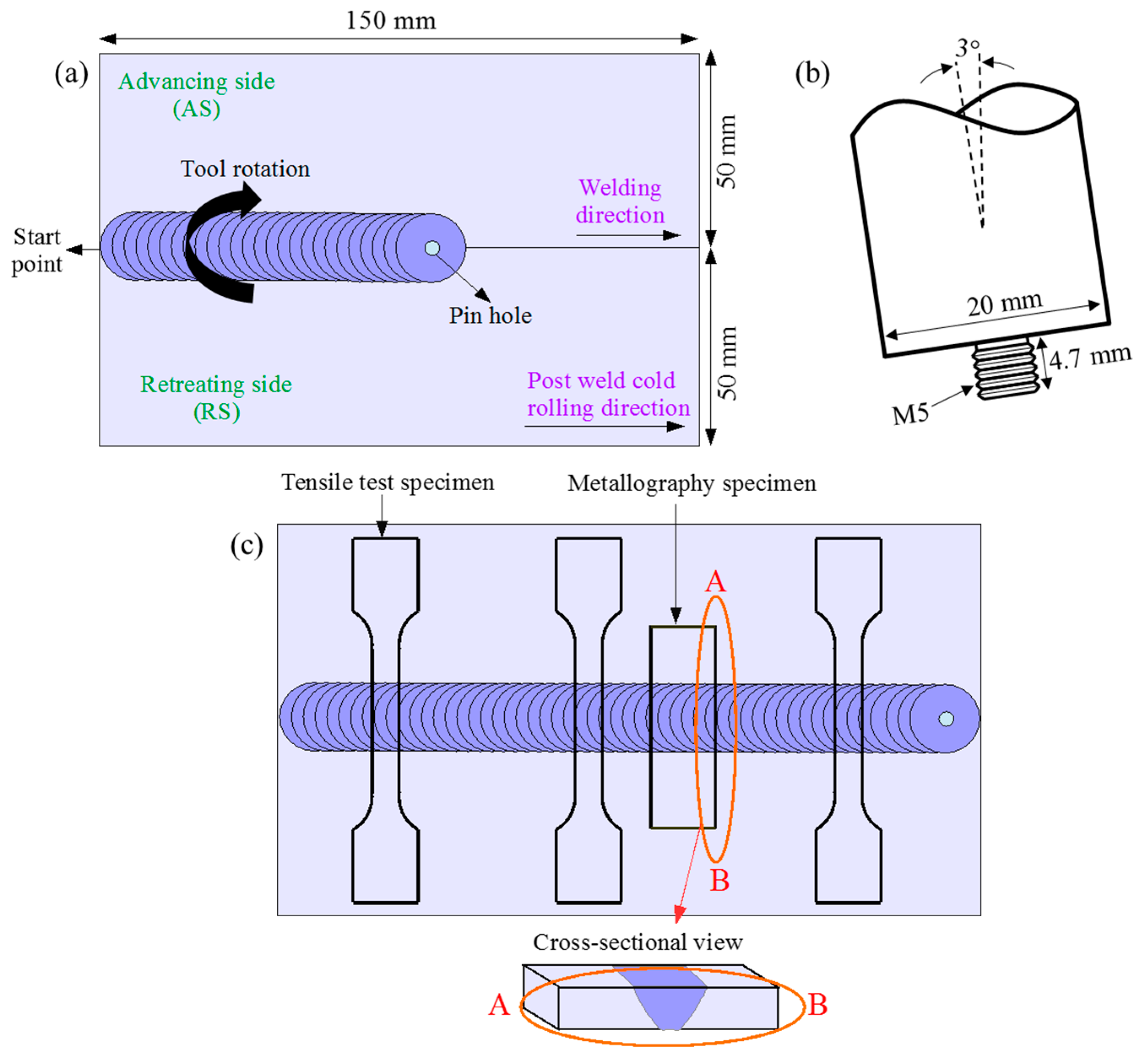
2. Materials and Methods
3. Results and Discussion
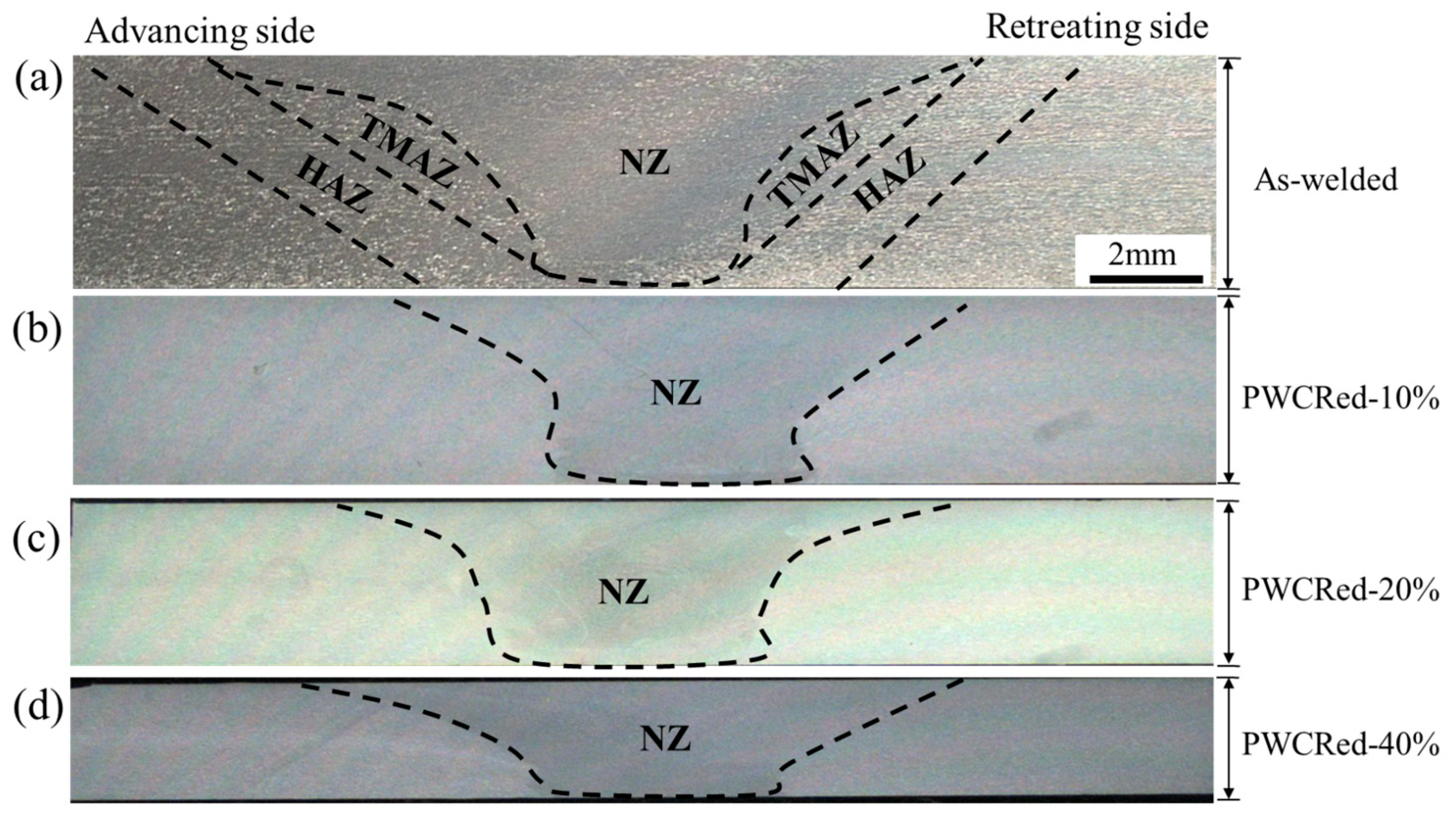
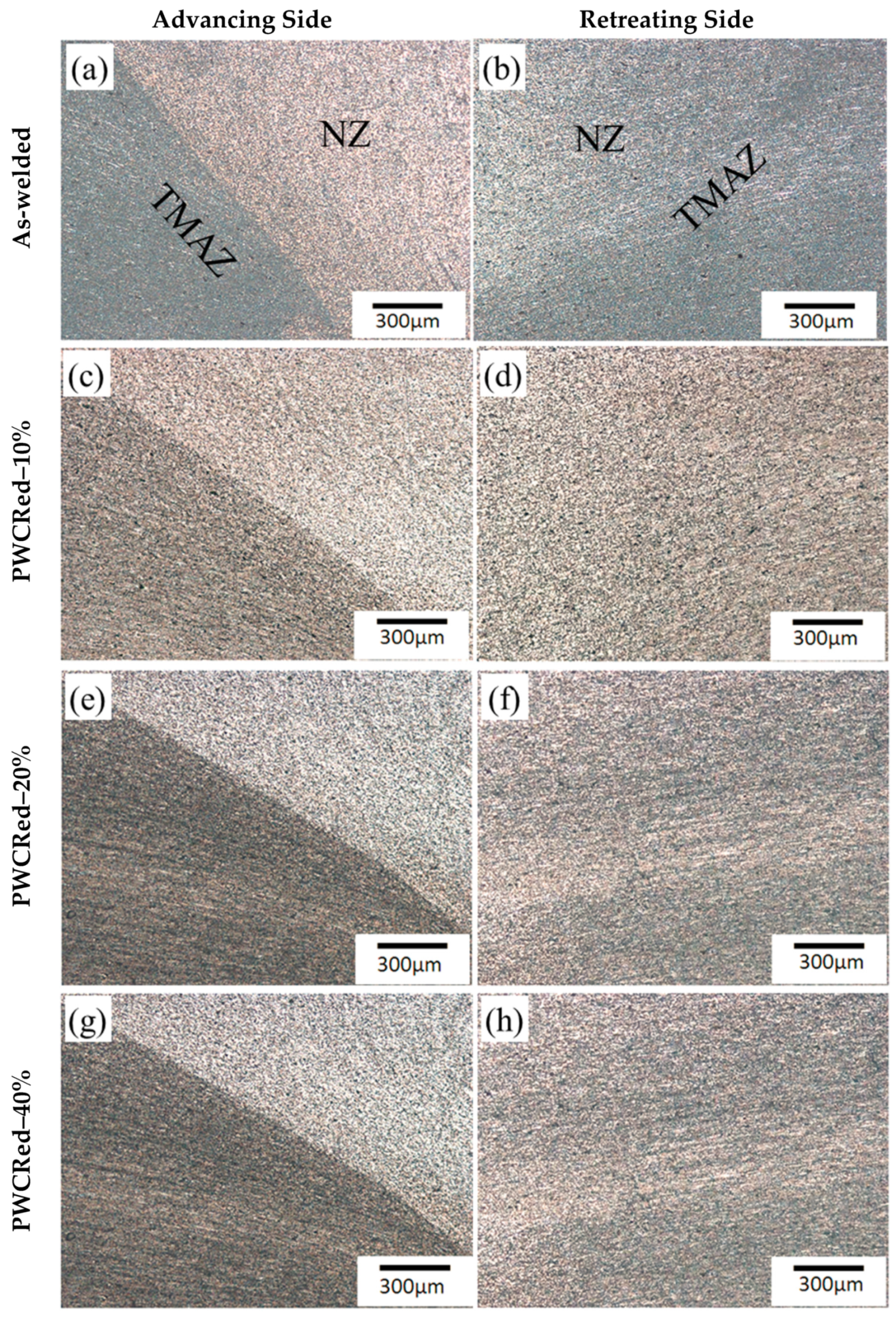
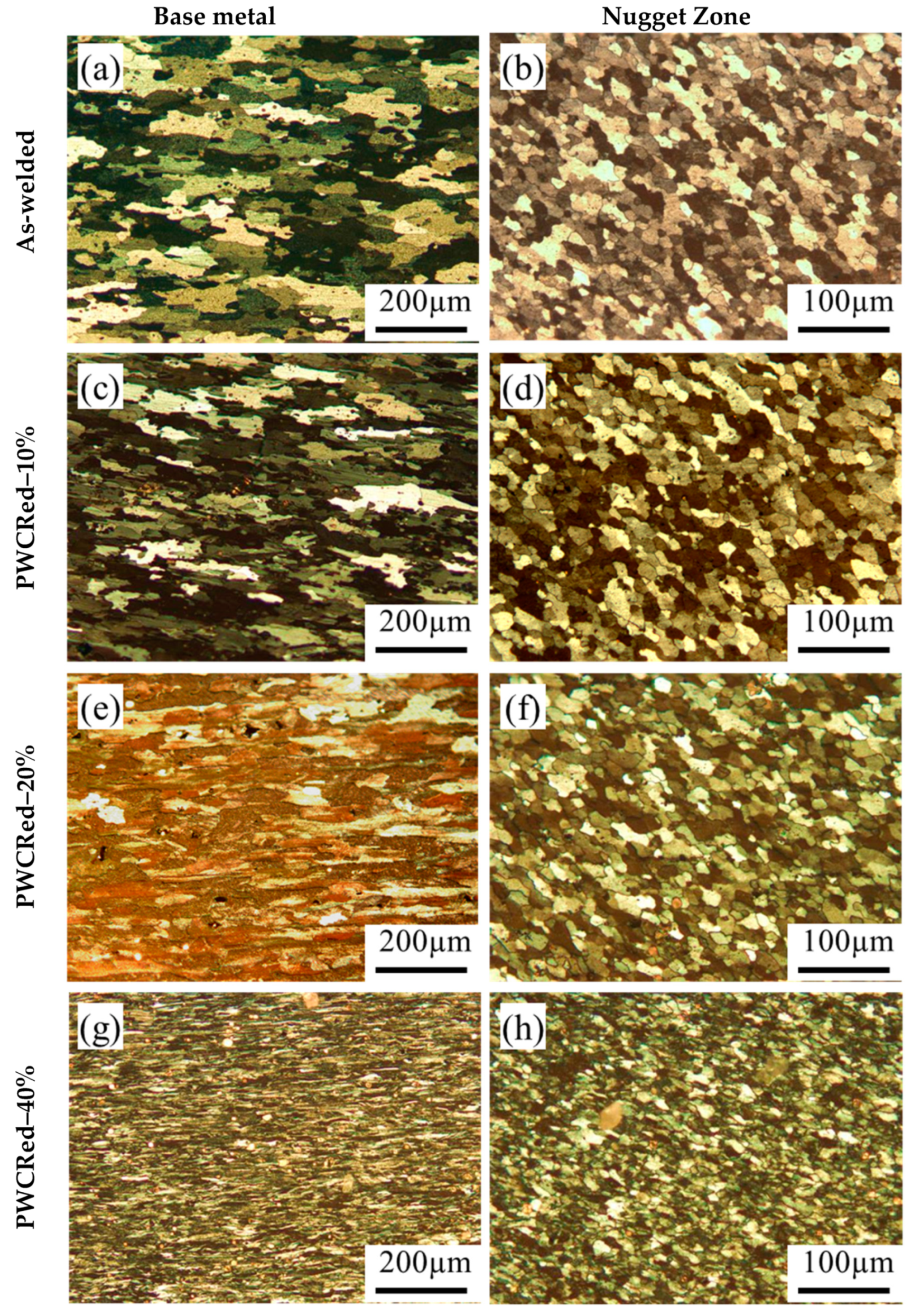
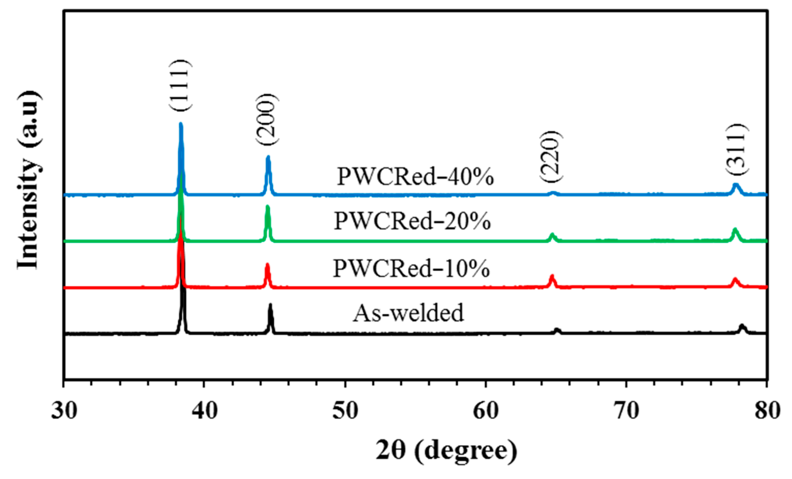
3.1. Microstructure
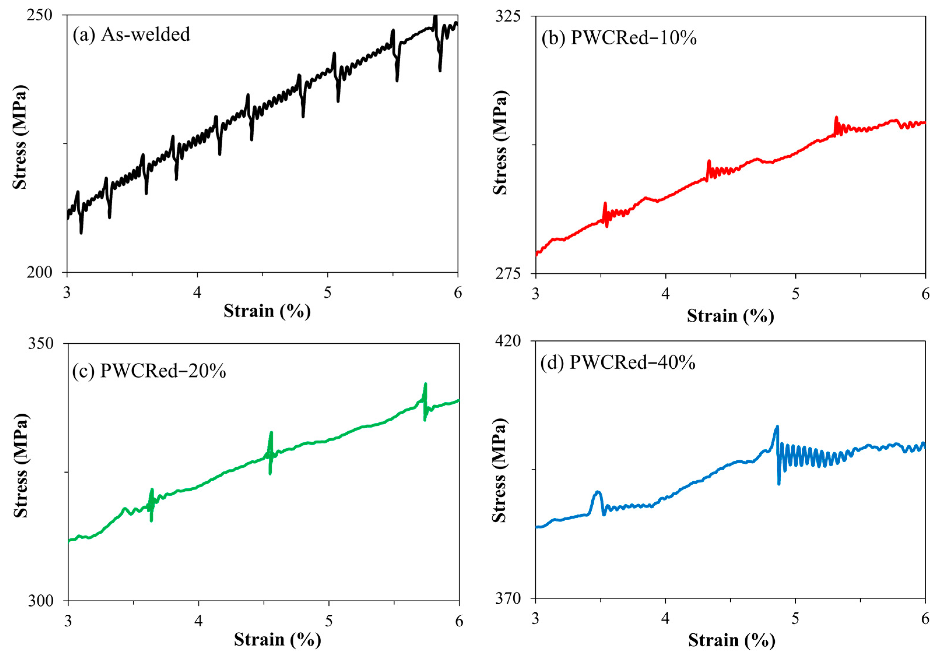
3.2. Tensile Properties
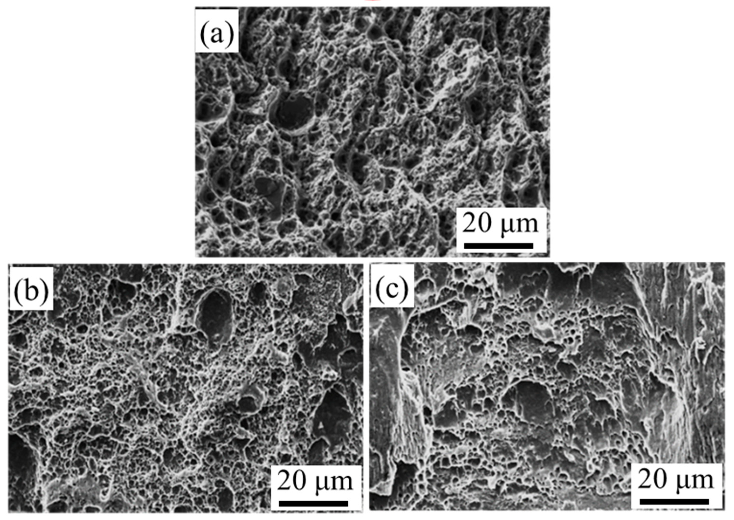
3.3. Fractography
3.4. Vickers Hardness
4. Conclusions
Author Contributions
Funding
Conflicts of Interest
References
- Missori, S.; Sili, A. Mechanical behaviour of 6082-T6 aluminium alloy welds. Metall. Sci. Technol. 2000, 18, 12–18. [Google Scholar]
- Poznak, A.; Freiberg, D.; Sanders, P. Automotive Wrought Aluminium Alloys. In Fundamentals of Aluminium Metallurgy; Elsevier: Amsterdam, The Netherlands, 2018; pp. 333–386. [Google Scholar]
- Demir, H.; Gündüz, S. The effects of aging on machinability of 6061 aluminium alloy. Mater. Des. 2009, 30, 1480–1483. [Google Scholar] [CrossRef]
- Elangovan, K.; Balasubramanian, V. Influences of post-weld heat treatment on tensile properties of friction stir-welded AA6061 aluminum alloy joints. Mater. Charact. 2008, 59, 1168–1177. [Google Scholar] [CrossRef]
- Wang, B.; Xue, S.; Ma, C.; Wang, J.; Lin, Z. Effects of porosity, heat input and post-weld heat treatment on the microstructure and mechanical properties of TIG welded joints of AA6082-T6. Metals 2017, 7, 463. [Google Scholar] [CrossRef] [Green Version]
- Deekhunthod, R.N. Weld Quality in Aluminium Alloys. Master’s Thesis, University of Uppsala, Uppsala, Sweden, 23 May 2014. [Google Scholar]
- Carron, D.; Bastid, P.; Yin, Y.; Faulkner, R.G. Modelling of precipitation during friction stir welding of an Al-Mg-Si alloy. Tech. Mech. 2010, 30, 29–44. [Google Scholar]
- Dong, J.; Zhang, D.; Zhang, W.; Zhang, W.; Qiu, C. Microstructure evolution during dissimilar friction stir welding of AA7003-T4 and AA6060-T4. Materials 2018, 11, 342. [Google Scholar] [CrossRef] [Green Version]
- Selamat, N.F.M.; Baghdadi, A.H.; Sajuri, Z.; Kokabi, A.H. Friction stir welding of similar and dissimilar aluminium alloys for automotive applications. Int. J. Automot. Mech. Eng. 2016, 13, 3401. [Google Scholar] [CrossRef]
- Baghdadi, A.H.; Selamat, N.F.M.; Sajuri, Z. Effect of tool offsetting on microstructure and mechanical properties dissimilar friction stir welded Mg-Al alloys. IOP Conf. Ser. Mater. Sci. Eng. 2017, 238, 12018. [Google Scholar] [CrossRef]
- Nakamura, T.; Obikawa, T.; Nishizaki, I.; Enomoto, M.; Fang, Z. Friction stir welding of non-heat-treatable high-strength alloy 5083-O. Metals 2018, 8, 208. [Google Scholar] [CrossRef] [Green Version]
- Picot, F.; Gueydan, A.; Martinez, M.; Moisy, F.; Hug, E. A correlation between the ultimate shear stress and the thickness affected by intermetallic compounds in friction stir welding of dissimilar aluminum alloy–stainless steel joints. Metals 2018, 8, 179. [Google Scholar] [CrossRef] [Green Version]
- Osman, N.; Sajuri, Z.; Baghdadi, A.H.; Omar, M.Z. Effect of process parameters on interfacial bonding properties of aluminium-copper clad sheet processed by multi-pass friction stir-welding technique. Metals 2019, 9, 1159. [Google Scholar] [CrossRef] [Green Version]
- Shah, S.; Tosunoglu, S. Friction stir welding: Current state of the art and future prospects. In Proceedings of the 16th World Multi-Conference on Systemics, Cybernetics and Informatics, Orlando, FA, USA, 17–20 July 2012; pp. 17–20. [Google Scholar]
- Sibalic, N.; Vukcevic, M. Numerical Simulation for FSW Process at Welding Aluminium Alloy AA6082-T6. Metals 2019, 9, 747. [Google Scholar] [CrossRef] [Green Version]
- Amini, A.; Asadi, P.; Zolghadr, P. Friction stir welding applications in industry. In Advances in Friction-Stir Welding and Processing; Elsevier: Amsterdam, The Netherlands, 2014; pp. 671–722. [Google Scholar]
- Selamat, N.M.; Baghdadi, A.H.; Sajuri, Z.; Kokabi, A.H.; Junaidi, S. Effect of rolling on strength of friction stir welded joint of aluminium alloys. J. Kejuruter. 2018, 1, 9–15. [Google Scholar]
- Baghdadi, A.H.; Selamat, N.F.M.; Sajuri, Z.; Kokabi, A.H. Effect of travel speed on quality and welding efficiency of friction stir welded AZ31B magnesium alloy. Int. J. Eng. Technol. (UAE) 2018, 7, 94–99. [Google Scholar] [CrossRef]
- Baghdadi, A.H.; Sajuri, Z.; MohamadSelamat, N.F.; Omar, M.Z.; Miyashita, Y.; Kokabi, A.H. Effect of intermetallic compounds on the fracture behavior of dissimilar friction stir welding joints of Mg and Al alloys. Int. J. Miner. Metall. Mater. 2019. Accepted. [Google Scholar] [CrossRef]
- Baragetti, S.; Urso, G.D. Aluminum 6060-T6 friction stir welded butt joints: Fatigue resistance with different tools and feed rates. J. Mech. Sci. Technol. 2014, 28, 11–14. [Google Scholar] [CrossRef]
- Selamat, N.F.M.; Baghdadi, A.H.; Sajuri, Z.; Kokabi, A.H. Weldability and mechanical properties of dissimilar al-mgsi to pure aluminium and al-mg using friction stir welding process. J. Teknol. 2019, 81, 143–149. [Google Scholar] [CrossRef] [Green Version]
- Threadgill, P.L.; Leonard, A.J.; Shercliff, H.R.; Withers, P.J. Friction stir welding of aluminium alloys. Int. Mater. Rev. 2009, 54, 49–93. [Google Scholar] [CrossRef]
- Liu, X.; Xie, P.; Wimpory, R.; Li, W.; Lai, R.; Li, M.; Chen, D.; Liu, Y.; Zhao, H. Residual stress, microstructure and mechanical properties in thick 6005A-T6 aluminium alloy friction stir welds. Metals 2019, 9, 803. [Google Scholar] [CrossRef] [Green Version]
- Behnagh, R.A.; Besharati Givi, M.K.; Akbari, M. Mechanical properties, corrosion resistance, and microstructural changes during friction stir processing of 5083 aluminum rolled plates. Mater. Manuf. Process. 2012, 27, 636–640. [Google Scholar] [CrossRef]
- Rao, D.; Huber, K.; Heerens, J.; Dos Santos, J.F.; Huber, N. Asymmetric mechanical properties and tensile behaviour prediction of aluminium alloy 5083 friction stir welding joints. Mater. Sci. Eng. 2013, 565, 44–50. [Google Scholar] [CrossRef] [Green Version]
- Borrego, L.P.; Costa, J.D.; Jesus, J.S.; Loureiro, A.R.; Ferreira, J.M. Fatigue life improvement by friction stir processing of 5083 aluminium alloy MIG butt welds. Theor. Appl. Fract. Mech. 2014, 70, 68–74. [Google Scholar] [CrossRef]
- Koilraj, M.; Sundareswaran, V.; Vijayan, S.; Koteswara Rao, S.R. Friction stir welding of dissimilar aluminum alloys AA2219 to AA5083-Optimization of process parameters using Taguchi technique. Mater. Des. 2012, 42, 1–7. [Google Scholar] [CrossRef]
- Bintu, A.; Vincze, G.; Picu, R.C.; Lopes, A.B. Effect of symmetric and asymmetric rolling on the mechanical properties of AA5182. Mater. Des. 2016, 100, 151–156. [Google Scholar] [CrossRef]
- Leal, R.M.; Loureiro, A. Effect of overlapping friction stir welding passes in the quality of welds of aluminium alloys. Mater. Des. 2008, 29, 982–991. [Google Scholar] [CrossRef]
- Gabrielli, F.; Forcellese, A.; El Mehtedi, M.; Simoncini, M. Mechanical properties and formability of cold rolled friction stir welded sheets in AA5754 for automotive applications. Procedia Eng. 2017, 183, 245–250. [Google Scholar] [CrossRef]
- Ozturk, F.; Sisman, A.; Toros, S.; Kilic, S.; Picu, R.C. Influence of aging treatment on mechanical properties of 6061 aluminum alloy. Mater. Des. 2010, 31, 972–975. [Google Scholar] [CrossRef]
- Bayley, C.J.; Pilkey, A.K. Influence of welding defects on the localization behaviour of an aluminum alloy tailor-welded blank. Mater. Sci. Eng. 2005, 403, 1–10. [Google Scholar] [CrossRef]
- Sato, Y.S.; Kokawa, H.; Enomoto, M.; Jogan, S. Microstructural evolution of 6063 aluminum during friction-stir welding. Metall. Mater. Trans. 1999, 30, 2429–2437. [Google Scholar] [CrossRef]
- Hamed, J.A. Effect of welding heat input and post-weld aging time on microstructure and mechanical properties in dissimilar friction stir welded AA7075–AA5086. Trans. Nonferr. Met. Soc. China 2017, 27, 1707–1715. [Google Scholar] [CrossRef]
- Pabandi, H.K.; Jashnani, H.R.; Paidar, M. Effect of precipitation hardening heat treatment on mechanical and microstructure features of dissimilar friction stir welded AA2024-T6 and AA6061-T6 alloys. J. Manuf. Process. 2018, 31, 214–220. [Google Scholar] [CrossRef]
- Syarif, J.; Nakashima, K.; Tsuchiyama, T.; Takaki, S. Effect of solute copper on yield strength in dislocation-strengthened steels. ISIJ Int. 2007, 47, 340–345. [Google Scholar] [CrossRef] [Green Version]
- Kozlov, E.V.; Koneva, N.A.; Popova, N.A. Grain structure, geometrically necessary dislocations and second-phase particles in polycrystals of micro-and mesolevels. Phys. Mesomech. 2009, 12, 280–292. [Google Scholar] [CrossRef]
- Abbass, M.K.; Ameen, H.A.; Hassan, K.S. Effect of heat treatment on corrosion resistance of friction stir welded AA 2024 aluminum alloy. Am. J. Sci. Ind. Res. 2011, 2, 297–306. [Google Scholar] [CrossRef]
- Lee, W.-B.; Kim, J.-W.; Yeon, Y.-M.; Jung, S.-B. The joint characteristics of friction stir welded AZ91D magnesium alloy. Mater. Trans. 2003, 44, 917–923. [Google Scholar] [CrossRef] [Green Version]
- Verdier, M.; Janecek, M.; Brechet, Y.; Guyot, P. Microstructural evolution during recovery in Al–2.5% Mg alloys. Mater. Sci. Eng. A 1998, 248, 187–197. [Google Scholar] [CrossRef]
- Zhang, Y.; Liu, J.P.; Chen, S.Y.; Xie, X.; Liaw, P.K.; Dahmen, K.A.; Qiao, J.W.; Wang, Y.L. Serration and noise behaviors in materials. Prog. Mater. Sci. 2017, 90, 358–460. [Google Scholar] [CrossRef]
- Härtel, M.; Illgen, C.; Frint, P.; Wagner, M. On the PLC effect in a particle reinforced AA2017 alloy. Metals 2018, 8, 88. [Google Scholar] [CrossRef] [Green Version]
- Sarkar, A.; Chatterjee, A.; Barat, P.; Mukherjee, P. Chaotic Behavior of the Portevin-Le Chatelier Effect in Low Carbon Steel. In Proceedings of the National Conference on Nonlinear Science and Dynamics, Chennai, India, 1–4 Feburay 2006. [Google Scholar]
- Yilmaz, A. The Portevin–Le Chatelier effect: A review of experimental findings. Sci. Technol. Adv. Mater. 2011, 12, 63001. [Google Scholar] [CrossRef]
- Pink, E. Features of the Portein-Le Chatelier effect in a low carbon steel. Scr. Metall. Mater. 1994, 30, 767–768. [Google Scholar] [CrossRef]
- Fu, S.; Zhang, Q.; Hu, Q.; Gong, M.; Cao, P.; Liu, H. The influence of temperature on the PLC effect in Al-Mg alloy. Sci. China Technol. Sci. 2011, 54, 1389–1393. [Google Scholar] [CrossRef]
- Ling, C.P.; McCormick, P.G. The effect of temperature on strain rate sensitivity in an Al-Mg-Si alloy. Acta Metall. Mater. 1993, 41, 3127–3131. [Google Scholar] [CrossRef]
- Dini, G.; Ueji, R.; Najafizadeh, A.; Monir-Vaghefi, S.M. Flow stress analysis of TWIP steel via the XRD measurement of dislocation density. Mater. Sci. Eng. A 2010, 527, 2759–2763. [Google Scholar] [CrossRef]
- Baghdadi, A.H.; Rajabi, A.; Selamat, N.F.M.; Sajuri, Z.; Omar, M.Z. Effect of post-weld heat treatment on mechanical behaviour and dislocation density of FSWed Al 6061. Mater. Sci. Eng. A 2019, 754, 728–734. [Google Scholar] [CrossRef]
- Malopheyev, S.; Kulitskiy, V.; Mironov, S.; Zhemchuzhnikova, D.; Kaibyshev, R. Friction-stir welding of an Al-Mg-Sc-Zr alloy in as-fabricated and work-hardened conditions. Mater. Sci. Eng. A 2014, 600, 159–170. [Google Scholar] [CrossRef]
- Zhang, Z.; Yang, X.; Zhang, J.; Zhou, G.; Xu, X.; Zou, B. Effect of welding parameters on microstructure and mechanical properties of friction stir spot welded 5052 aluminum alloy. Mater. Des. 2011, 32, 4461–4470. [Google Scholar] [CrossRef]
- Razavi, M.; Rahimipour, M.R.; Rajabi, A. Prenucleation effect on characterisations of synthesised nanocrystalline tungsten carbide via mechanical milling. Mater. Technol. 2013, 28, 145–154. [Google Scholar] [CrossRef]
- Rajabi, A.; Ghazali, M.J. Quantitative analyses of TiC nanopowders via mechanical alloying method. Ceram. Int. 2017, 43, 14233–14243. [Google Scholar] [CrossRef]
- Kalita, M.P.C.; Deka, K.; Das, J.; Hazarika, N.; Dey, P.; Das, R.; Paul, S.; Sarmah, T.; Sarma, B.K. X-ray diffraction line profile analysis of chemically synthesized lead sulphide nanocrystals. Mater. Lett. 2012, 87, 84–86. [Google Scholar] [CrossRef]
- Deevi, S.; Deevi, S.C.; Verneker, V.R.P. Reactivities of aluminium and aluminium-magnesium alloy powders in polymeric composites. J. Mater. Sci. 1996, 31, 1043–1051. [Google Scholar] [CrossRef]
- Salahi, E.; Rajabi, A. Fabrication and characterisation of copper–alumina nanocomposites prepared by high-energy fast milling. Mater. Sci. Technol. 2016, 32, 1212–1217. [Google Scholar] [CrossRef]
- Sharma, C.; Upadhyay, V.; Dwivedi, D.K.; Kumar, P. Mechanical properties of friction stir welded armor grade Al–Zn–Mg alloy joints. Trans. Nonferr. Met. Soc. China 2017, 27, 493–506. [Google Scholar] [CrossRef]
- Armstrong, R.W. Hall–Petch Relationship: Use in Characterizing Properties of Aluminum and Aluminum Alloys. In Encyclopedia of Aluminum and It Alloys; Totton, G.E., Tiryakioglu, M., Eds.; Taylor & Francis Group: London, UK, 2016. [Google Scholar]


| Al | Mg | Mn | Cr | Si | Fe |
|---|---|---|---|---|---|
| Balance | 4.46 | 1.0 | 0.14 | 0.25 | 0.45 |
| Sample | Tensile Strength (MPa) | Elongation (%) | Welding Efficiency (%) |
|---|---|---|---|
| AA5083-BM | 328 | 22 | - |
| As-welded | 262 | 7.3 | 80 |
| PWCRed–10% | 321 | 8.6 | 98 |
| PWCRed–20% | 350 | 8.4 | 107 |
| PWCRed–40% | 403 | 7.9 | 123 |
| Sample | Y = αX + β | d (n.m) | ⴄ (%) | |
|---|---|---|---|---|
| α | β | |||
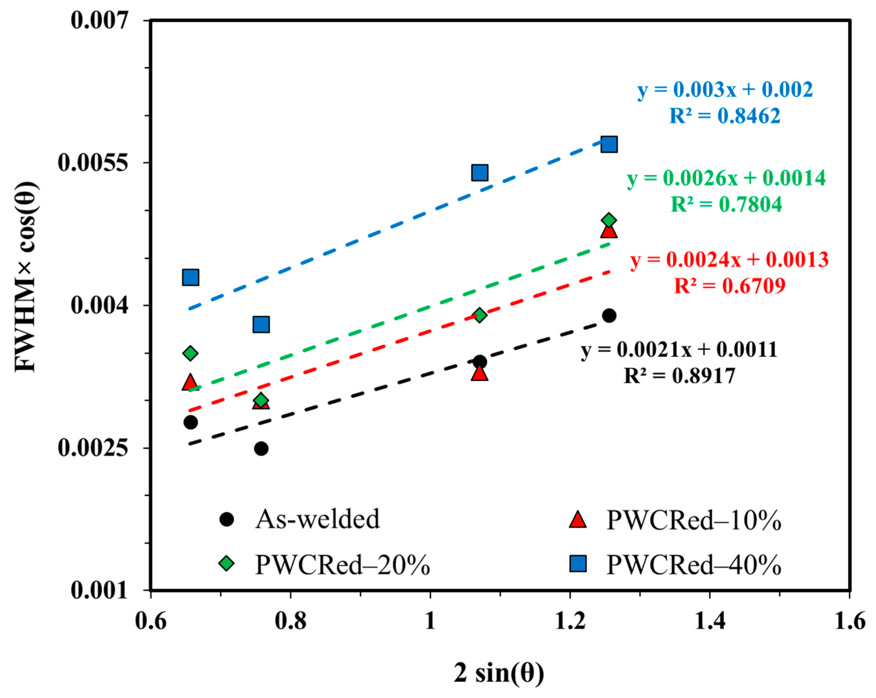
| As-welded | 0.0021 | 0.0011 | 126.08 | 0.21 |
| PWCRed–10% | 0.0024 | 0.0013 | 106.68 | 0.24 |
| PWCRed–20% | 0.0026 | 0.0014 | 99.06 | 0.26 |
| PWCRed–40% | 0.0030 | 0.0020 | 69.35 | 0.30 |
| Sample | a (Nelson–Riley Method) (Å) | b (10−10 m) | ρ × 1014 (m−2) |
|---|---|---|---|
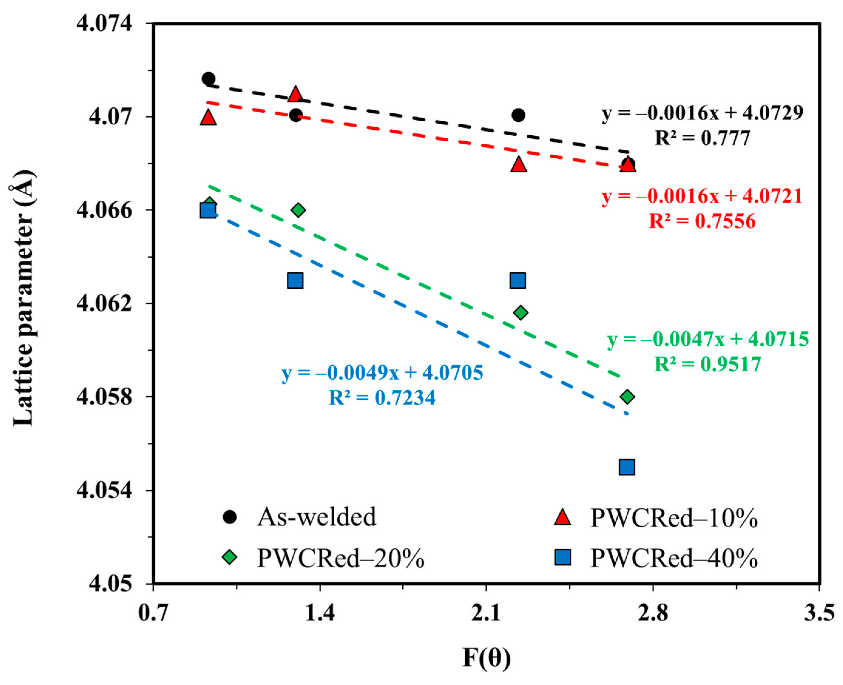
| As-welded | 4.0729 | 2.87998 | 2.00340 |
| PWCRed–10% | 4.0721 | 2.87941 | 2.70643 |
| PWCRed–20% | 4.0715 | 2.87899 | 3.15797 |
| PWCRed–40% | 4.0705 | 2.87828 | 5.20672 |
© 2020 by the authors. Licensee MDPI, Basel, Switzerland. This article is an open access article distributed under the terms and conditions of the Creative Commons Attribution (CC BY) license (http://creativecommons.org/licenses/by/4.0/).
Share and Cite
Sajuri, Z.; Mohamad Selamat, N.F.; Baghdadi, A.H.; Rajabi, A.; Omar, M.Z.; Kokabi, A.H.; Syarif, J. Cold-Rolling Strain Hardening Effect on the Microstructure, Serration-Flow Behaviour and Dislocation Density of Friction Stir Welded AA5083. Metals 2020, 10, 70. https://0-doi-org.brum.beds.ac.uk/10.3390/met10010070
Sajuri Z, Mohamad Selamat NF, Baghdadi AH, Rajabi A, Omar MZ, Kokabi AH, Syarif J. Cold-Rolling Strain Hardening Effect on the Microstructure, Serration-Flow Behaviour and Dislocation Density of Friction Stir Welded AA5083. Metals. 2020; 10(1):70. https://0-doi-org.brum.beds.ac.uk/10.3390/met10010070
Chicago/Turabian StyleSajuri, Zainuddin, Nor Fazilah Mohamad Selamat, Amir Hossein Baghdadi, Armin Rajabi, Mohd Zaidi Omar, Amir Hossein Kokabi, and Junaidi Syarif. 2020. "Cold-Rolling Strain Hardening Effect on the Microstructure, Serration-Flow Behaviour and Dislocation Density of Friction Stir Welded AA5083" Metals 10, no. 1: 70. https://0-doi-org.brum.beds.ac.uk/10.3390/met10010070