Article

Evaluation of the Possibility of Obtaining Welded Joints of Plates from Al-Mg-Mn Aluminum Alloys, Strengthened by the Introduction of TiB2 Particles

Faculty of Physics and Engineering, National Research Tomsk State University, 36 Lenin Ave., 634050 Tomsk, Russia
*
Author to whom correspondence should be addressed.
Submission received: 21 July 2021 / Revised: 1 September 2021 / Accepted: 8 September 2021 / Published: 30 September 2021
(This article belongs to the Special Issue Light Metals and Their Composites)

Abstract

:
In the work, the possibility of obtaining strong welded joints of aluminum alloys modified with particles is demonstrated. For research, strengthened aluminum alloys of the Al-Mg-Mn system with the introduction of TiB2 particles were obtained. TiB2 particles in specially prepared Al-TiB master alloys obtained by self-propagating high-temperature synthesis were introduced ex situ into the melt according to an original technique using ultrasonic treatment. Plates from the studied cast alloys were butt-welded by one-sided welded joints of various depths. To obtain welded joints, the method of electron beam welding was used. Mechanical properties of the studied alloys and their welded joints under tension were studied. It was shown that the introduction of particles resulted in a change in the internal structure of the alloys, characterized by the formation of compact dendritic structures and a decrease in the average grain size from 155 to 95 µm. The change in the internal structure due to the introduction of particles led to an increase in the tensile strength of the obtained alloys from 163 to 204 MPa. It was found that the obtained joints have sufficient relative strength values. Relative strength values reach 0.9 of the nominal strength of materials already at the ratio of the welded joint depth to the thickness of the welded plates, equal to 0.6 for the initial alloy and in the range of 0.67–0.8 for strengthened alloys.

1. Introduction

Al-Mg alloys are widely used in aviation, marine transport, and pipeline design due to their high corrosion resistance and good weldability by conventional methods [1,2]. The deformable 1550 alloy refers to alloys of the Al-Mg system and is used in the form of rolled sheets. The highest values of properties for this alloy are achieved due to dispersion hardening with the introduction of such elements as zirconium or scandium [3,4,5]. The main disadvantage of this method of hardening is its high cost that leads to a significant increase in the product cost. In addition to dispersion hardening, methods of modifying the structure can be applied by grain refinement during the melt solidification and hardening the metal matrix by introducing non-metallic particles and fibers [6,7,8,9].
To modify the structure, chemical modifiers are introduced into aluminum alloys. Due to the close parameters of their crystal structure, modifiers are able to behave as supercooling centers in the melt during its crystallization [10]. The most widely used modifier for aluminum alloys is titanium diboride (TiB2). The TiB2 modifier is introduced ex situ using the Al-5Ti-1B master alloy [10,11,12] (containing Al3Ti and TiB2 particles within an aluminum matrix) or synthesized in situ using the K2TiF6 and KBF4 salts [13]. Recent studies have shown that TiB2 particles are not sufficiently active crystallization centers for grain refinement. This activity increases significantly when a two-dimensional Al3Ti compound is formed on their surface [10]. In Ref. [13], it was shown that the optimal particle size for their use as modifiers in aluminum alloys varies from 1 to 5 μm. An additional mechanism is dispersion hardening [14], which requires the use of particles up to 500 nm in size [15,16,17]. In this case, non-metallic nanoparticles should be uniformly distributed within an aluminum matrix and have a good bond with it, capable of being retained during the movement of dislocations. Due to their high hardness, TiB2 particles can be an effective obstacle to the movement of dislocations [18]. The simultaneous use of TiB2 particles for both modification and dispersion hardening of the aluminum alloy structure seems promising. For this purpose, master alloys of a given composition should be used containing TiB2 particles in a sufficient quantity within nano- and micro-size range. For example, in Reference [19], it was shown that the separate introduction of a mixture of modifying TiB2 microparticles and aluminum oxide nanoparticles makes it possible to modify the structure of and strengthen an aluminum matrix, increasing its hardness and electrical conductivity.
In terms of applications, most constructions are fabricated from Al-Mg alloys obtained by welding initial rolled sheets. As already mentioned, Al-Mg alloys have good weldability, so there is no need to develop special technologies for their welding. Due to their high Mg content, such alloys have good fracture toughness of welded joints. The most common welding technologies for Al-Mg alloys are argon-arc welding, plasma welding, and stir welding. Friction stir welding technology makes it possible to achieve a toughness of the welded joint up to three times higher in comparison with fusion welding [20]. For thin sheets, plasma arc welding is an effective method.
According to industry requirements, the strength of the welded joint must be at least 0.9 of the strength of the base metal. It depends both on the alloy itself and on the type of welding. Thus, the introduction of modifying additives that change the structure of the alloy can significantly affect the mechanical properties of its welded joints. In this regard, the development of methods for increasing the strength characteristics of alloys by introducing modifying additives requires taking into account the structure and mechanical properties of welded joints of sheets obtained from the modified alloy. Then the obtained properties should be compared with the properties of the initial cast alloy.
The purpose of this work is to assess the possibility of obtaining welded joints with permissible values of the relative strength of the aluminum alloy strengthened with TiB2 particles.

2. Materials and Methods

2.1. Obtaining Alloys

To achieve this purpose, two series of modified aluminum alloys were obtained, strengthened by the introduction of master alloys consisting of two types of powder systems with dispersed TiB2 particles.
A 1550 aluminum alloy (93.2 wt. % Al, 5.8 wt. % Mg, 0.6 wt. % Mn) was used as the initial alloy. Al-TiB2 master alloys were obtained by self-propagating high-temperature synthesis (SHS) from a powder mixture of aluminum, titanium, and boron [21]. The size of TiB2 particles formed during combustion and the phase composition of obtained master alloys were controlled by monitoring the main synthesis factors, such as a burning rate and temperature of the initial Al-Ti-B powder system. Information about the SHS process, chemical composition, and properties of the obtained master alloys were described in detail in Refs. [19,22].
After two synthesis experiments, the master alloys were obtained with a bimodal particle size distribution. The volume content of TiB2 particles of various sizes in the master alloys is presented in Table 1.
The obtained master alloys were introduced into the aluminum alloy melt with simultaneous ultrasonic treatment. Ultrasonic treatment was used to degass the melt [22] and improve the wettability of the surface of TiB2 particles [23].
The casting was carried out according to the following procedure. First, 1 kg of the 1550 alloy was placed into a graphite crucible, melted in a muffle furnace (780 °C), and held for 2 h. An ultrasonic waveguide was embedded into the melt, and the master alloy was introduced with simultaneous ultrasonic treatment at a melt temperature of 730 °C. Ultrasonic treatment was performed using a magnetostrictive water-cooled converter (with a power of 4.1 kV and a frequency of 17.6 kHz). After complete dissolution of the master alloy, ultrasonic treatment was continued for 2 min. The obtained melt was kept in the furnace for 30 min and then subjected to ultrasonic treatment for 2 min. The melt was poured into a steel chill mold at a temperature of 720 °C. The quantity of TiB2 particles in the alloy was approximately 4.5 × 10²⁰ pcs/kg. The initial 1550 alloy was obtained with similar casting parameters without introducing the master alloy. Thus, three types of alloys have been investigated: 1—the 1550 alloy without the master alloy and ultrasonic treatment; 2—the 1550 alloy with the master alloy 1 (according to Table 1) and ultrasonic treatment; 3—the 1550 alloy with the master alloy 2 (according to Table 1) and ultrasonic treatment.

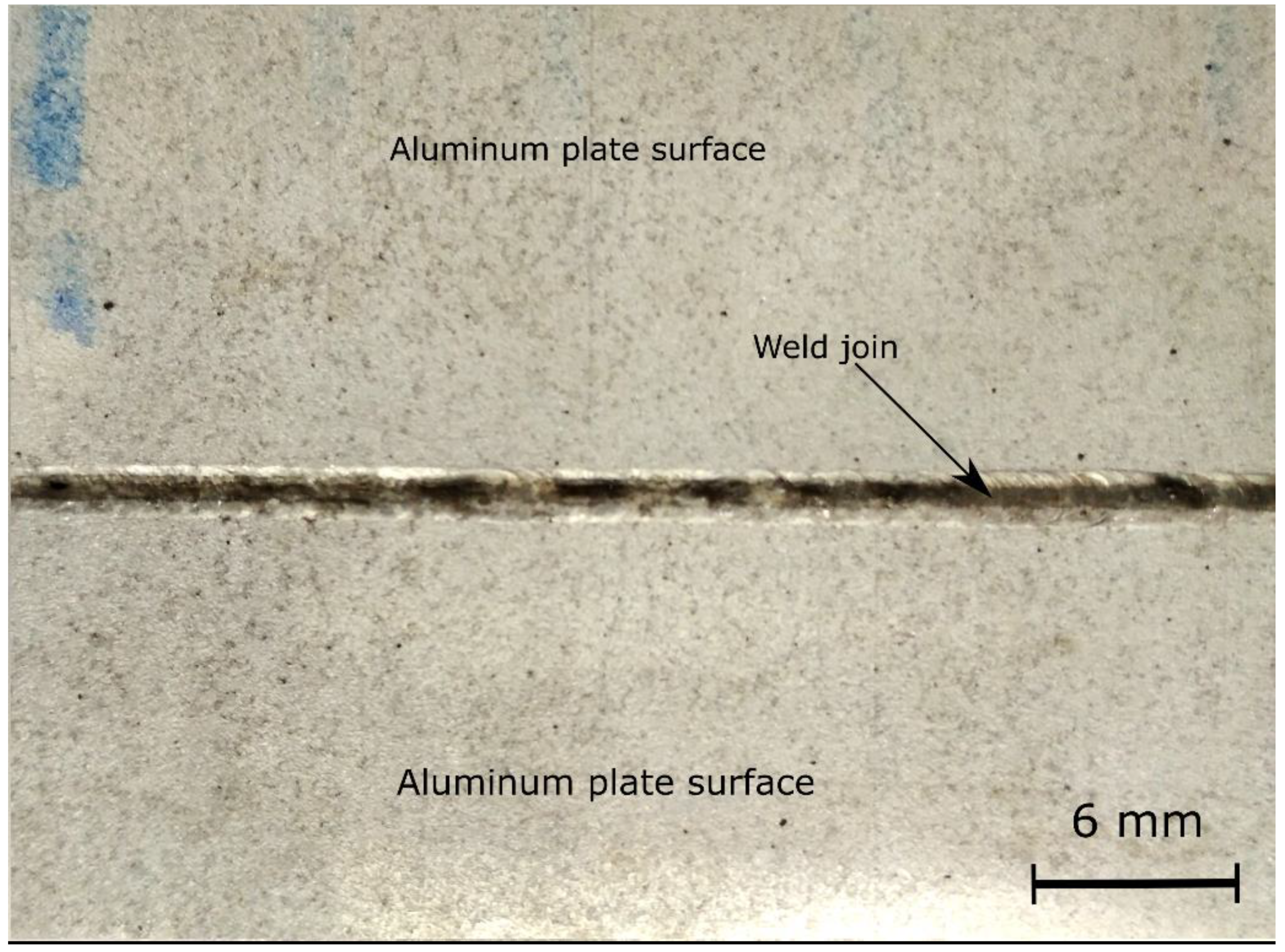
2.2. Welding of the Obtained Alloys

Aluminum plates for further welding of the three obtained alloys with a thickness and surface roughness Rz of 2 mm and 25 μm, respectively, were cut from prismatic castings using electrical discharge cutting. Before welding, the surface of the plates was degreased with acetone. Surface preparation prior to welding did not include chemical milling [24], which is mandatory for aluminum alloys when using other welding methods.
Electron beam welding of the plates of the studied alloys was performed without the use of filler material, which provides a melting mode without introducing chemical additives into the weld area. The main parameters of the electron-beam welding process are the position of the focal plane relative to the surface of the welded plates, the welding speed, current and voltage, and the use of shielding inert gases. The exposure time of the electron beam focused on the surface was varied with the welding speed of up to 25 mm/s, constant voltage of 28 kV, and electrical current of 35 mA. The exposure time affects the welding depth. The dependence of the ratio of the strength of the welded joints to the strength of the initial cast alloys at different welding depths was studied. Argon was used as an inert gas to protect the metal of the front side of the weld and its root part. Argon supply to the root of the weld is necessary to protect against the formation of oxides and increase the surface tension of the metal, which avoids sagging and undercuts in the weld.
An image of a typical front surface of the obtained weld is shown in Figure 1. The front parts of the welds have a flaky surface due to the alternate transverse movement of the electron beam from one plate to another.
As a result of using the described welding technique, welds with a width of approximately 2 mm and different depths were formed between the plates of the cast alloys. The depth of the weld was varied to obtain the one-sided joint with acceptable relative strength.

2.3. Structure Analysis

Metallographic analysis was performed using an Olympus GX71 (Olympus Scientific Solutions Americas, Waltham, MA, USA) optical microscope. The structure of the cast materials was studied after mechanical grinding, polishing, and etching of the surface of the samples with the Keller solution (0.5 HF−1.8 HCl2−2.7 HNO3−95 H2O). The average grain size was determined by the secant method according to the ASTM 112-13 standard based on the results of at least 300 measurements for each state. The selection of boundaries in optical images was performed using the Olympus Stream software (Olympus Scientific Solutions Americas, Waltham, MA, USA).
The fracture surfaces of the samples after tensile tests were examined using a digital microscope. The cross-sectional area of the weld was measured on the samples fractured after tensile tests with an accuracy of 1 μm.

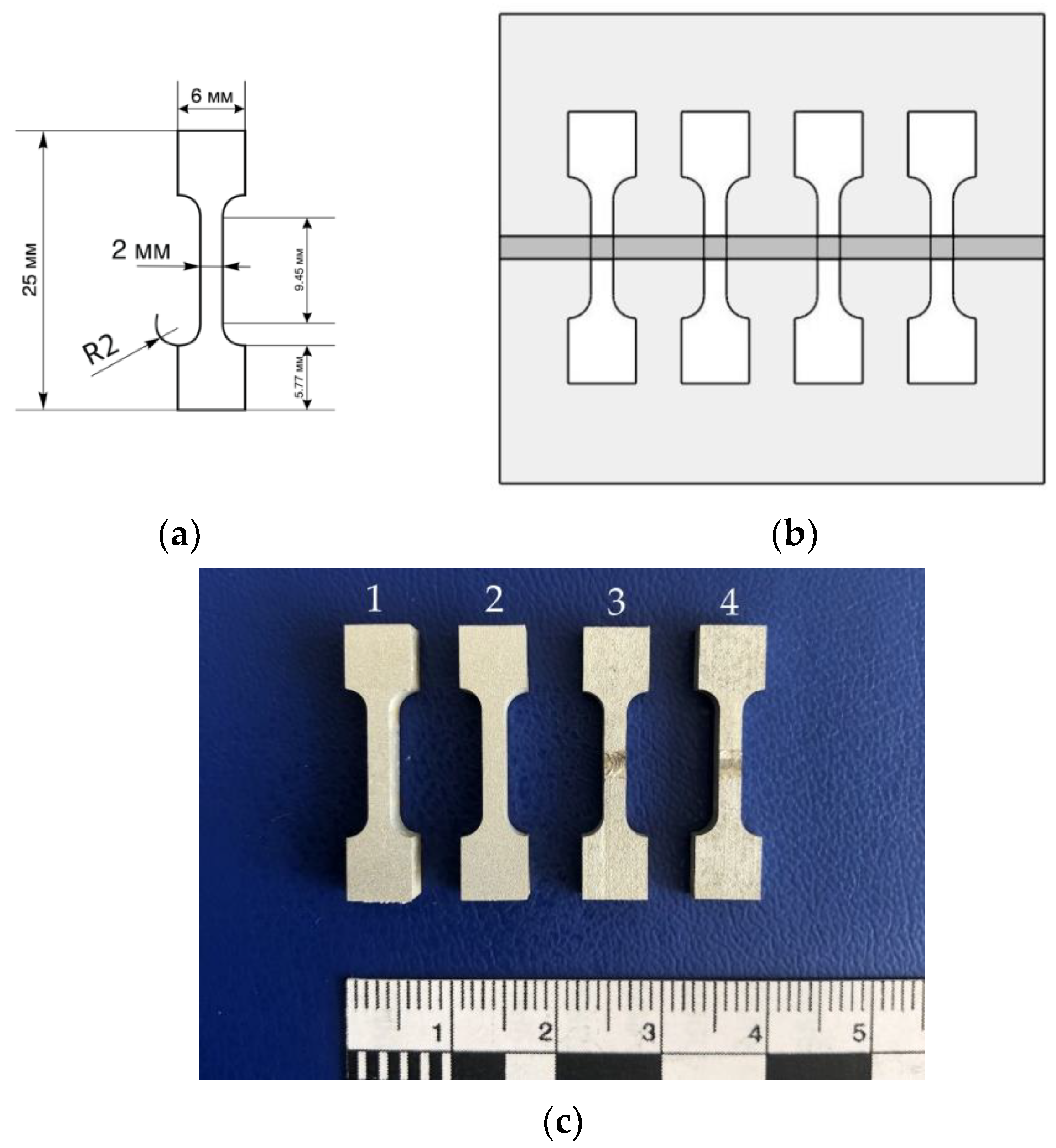
2.4. Mechanical Testing Methods

The ultimate tensile strength (UTS, MPa) of the welded joints was measured by the uniaxial tensile test. Samples of plates (the dimensions of which are presented in Figure 2a) were cut from the welded plates in a direction transverse to the weld direction with a weld in the middle of the working part of the sample for the tensile test. To compare UTS of the welded joints with UTS of the initial cast alloys, additional samples were cut out. The working part of the samples with the dimensions of 2 mm × 2 mm × 9.45 mm covered all zones of the weld, i.e., the weld core or the mixing zone, the thermomechanical test zone, and the base material. The scheme of sampling location on the plate with weld is shown in Figure 2b. A photograph of samples with and without welding is shown in Figure 2c.
Uniaxial tensile tests were performed using an Instron 5948 single table bench test system (Instron European Headquarters, High Wycombe, UK) with a maximum tensile (compressive) force of 2000 N. The tests were performed according to the ASTM E8M:2008 standard [25]. The test results were obtained in the form of stress-strain diagrams, based on which the values of UTS and elongation at fracture (ε, %) were found. To estimate the relative strength of the welded joints (σsv/σnom), the ratio of UTS obtained for the welded sample to UTS of the non-welded sample from the same alloy series was used. The number of samples for each series of tests was chosen based on a statistical sample of results, but not less than five samples.

3. Results and Discussion

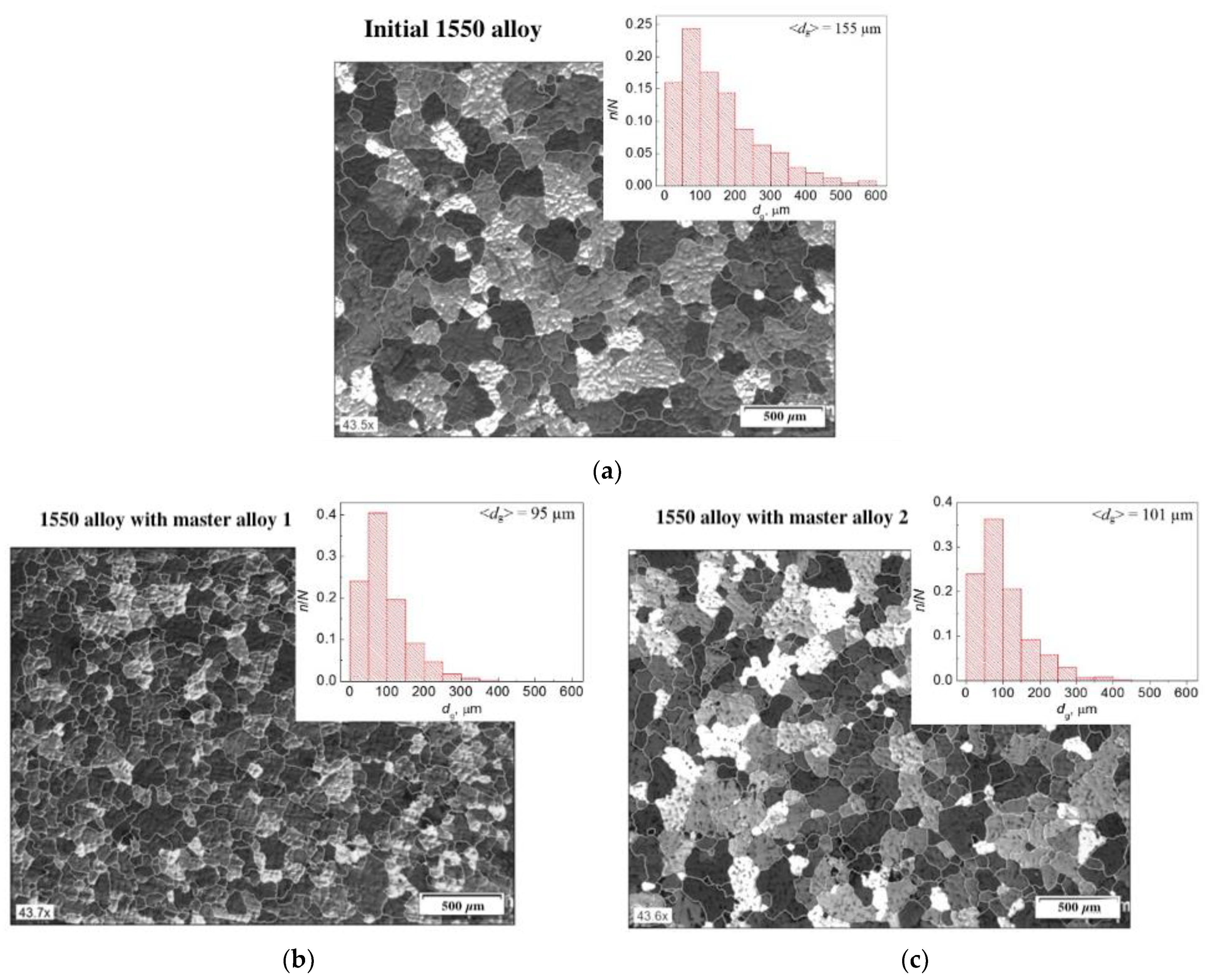
3.1. Alloy Microstructure

The effect of grain refinement of the Al-Mg alloys with TiB2 particles is shown in polarized optical images in Figure 3. Figure 3 also presents histograms of grain size distribution in the studied alloys without TiB2 particles and reinforced with the master alloys with different average sizes of TiB2 particles.
In the histograms, dg is the grain size, n and N are the number of grains of a certain size and the total number of measurements, respectively. As can be seen from Figure 3a, the initial alloy without particles has a rough and non-uniform dendritic structure with an average grain size of ~155 µm. The alloy was dominated by large primary dendrites with a complex shape. It was found that the addition of TiB2 particles to the alloy led to both a more uniform refinement of primary dendrites and the appearance of small equiaxed dendrites, depending on the master alloy composition. The obtained data indicate that TiB2 microparticles of various sizes contained in the master alloys refine the structure of the 1550 aluminum alloy. TiB2 particles synthesized by the SHS method behave as new crystallization centers as the melt is cooling down [10]. In general, the introduction of the master alloys 1 and 2 into the alloy reduced the average grain size of the alloy to ~95 and ~101 µm, respectively.

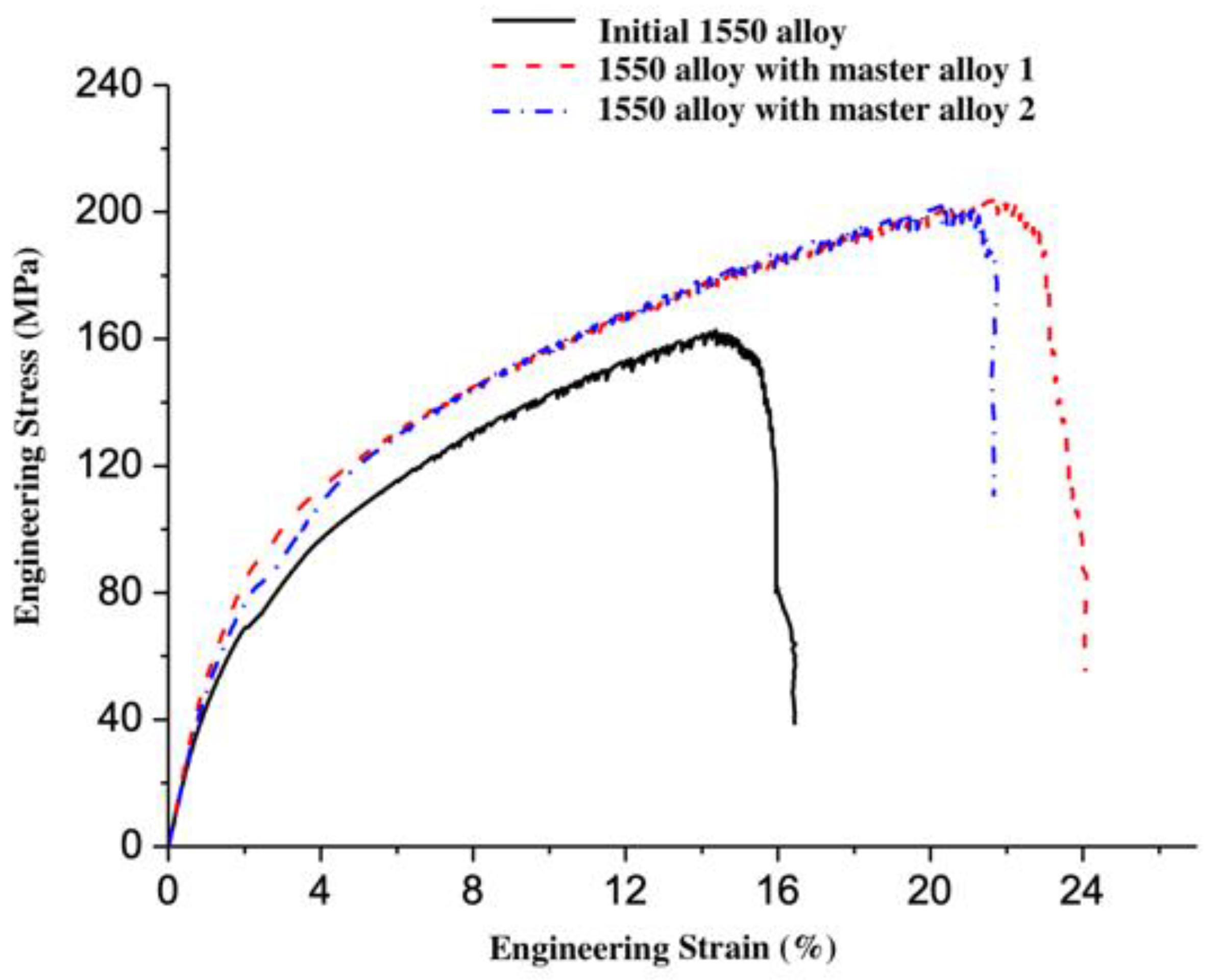
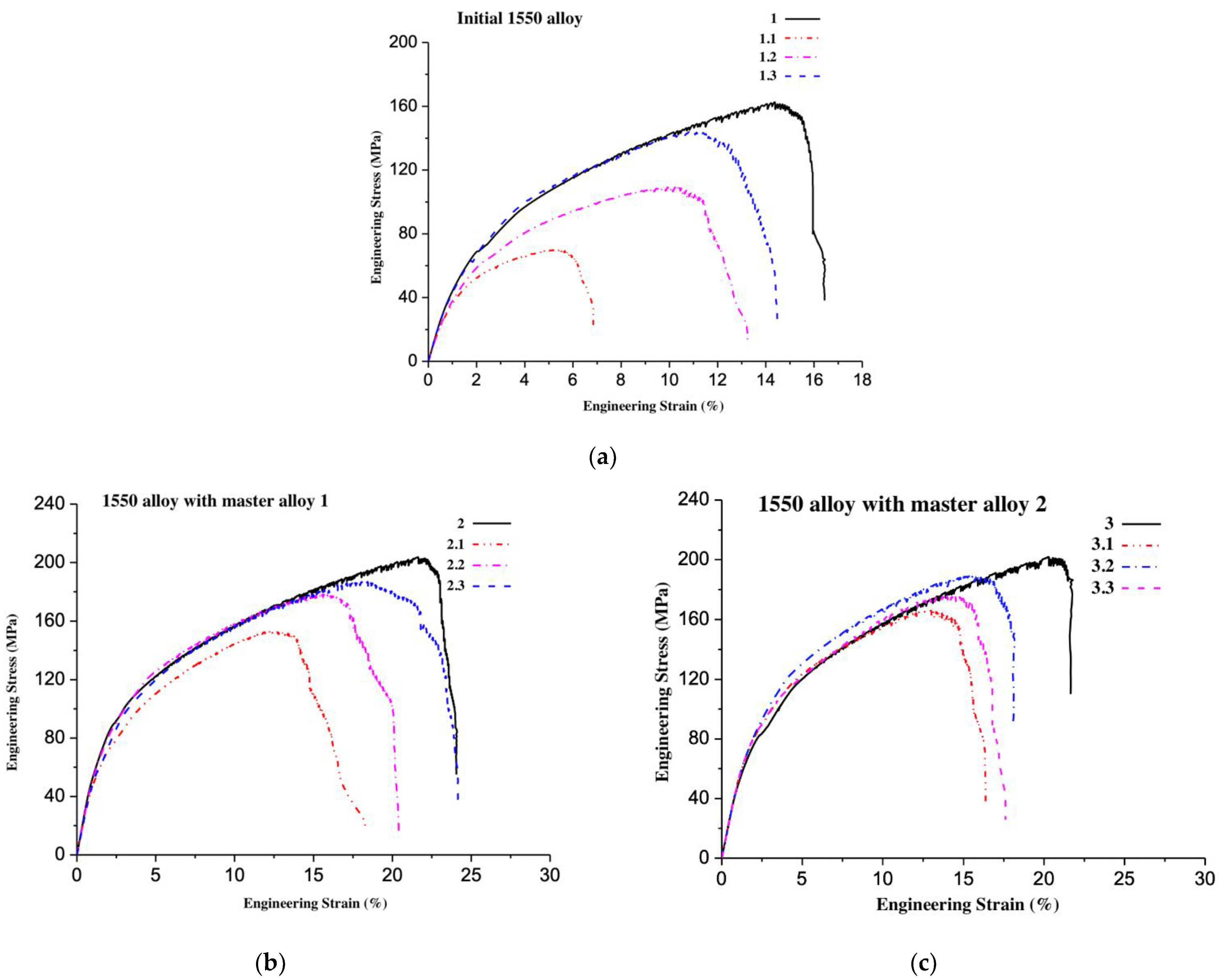
3.2. Mechanical Characteristics of the Initial Alloys

Typical deformation curves obtained during uniaxial tensile tests of samples of the studied aluminum alloys without welding are shown in Figure 4.
The obtained values of the UTS and elongation at fracture (ε, %) of the studied alloys are shown in Table 2.
As can be seen from Table 2, the introduction of TiB2 particles improves the mechanical characteristics compared to the initial 1550 alloy. UTS was 204 MPa and 202 MPa for the 1550 alloys reinforced with two types of Al-TiB2 master alloys, while UTS for the initial 1550 alloy was 163 MPa. Elongation at fracture also increased with the addition of TiB2 particles to the initial 1550 alloy from 16 to 22–24%. The obtained results were used as nominal values for further study of the strength of the welded joints.

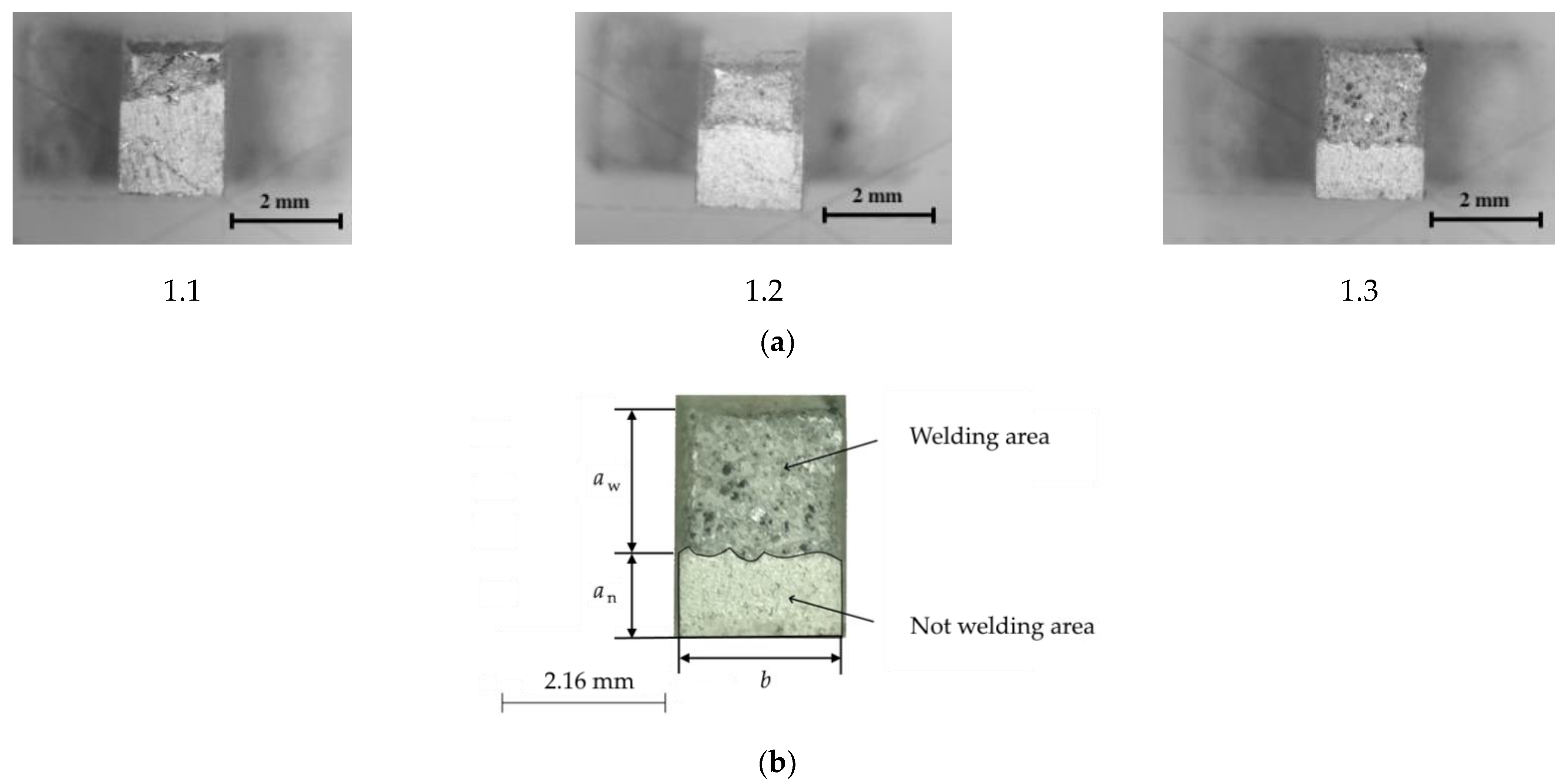
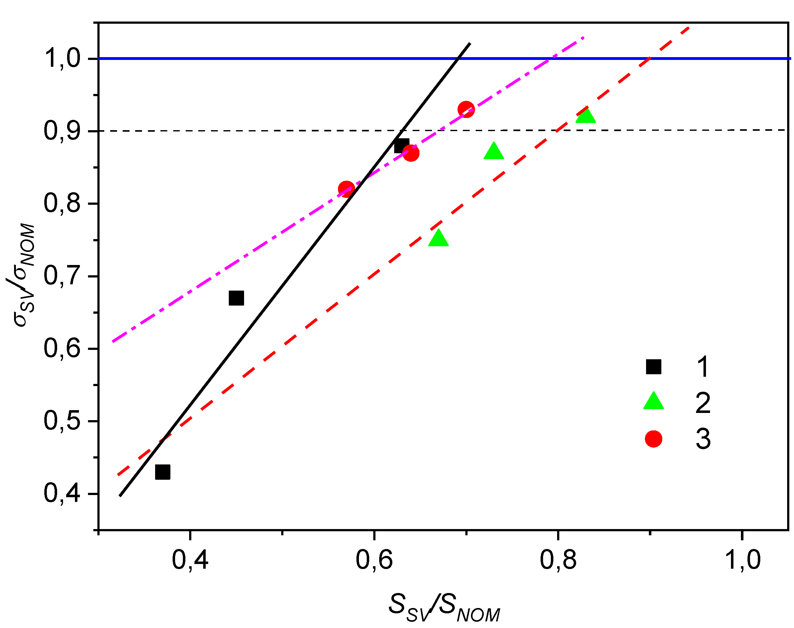
3.3. Mechanical Characteristics and Structure of Welded Joints

For each investigated series of alloys, three welding depths were estimated. To determine the UTS of each welded sample, it is necessary to know the cross-sectional area of the weld in the sample, which depends primarily on the width of the working part and the depth of the welded joint. The exact dimensions can be found only after the fracture of the sample in tension from the image of the end of the working part from the side of destruction. To obtain images and dimensions of surfaces, methods of optical microscopy with microscope hardware were used.
The cross-sectional images of the fracture of the studied samples are shown in Figure 5. This figure illustrates a technique for measuring the welding depth after tensile failure of specimens. The images clearly show welded and non-welded areas. The images located from left to right show an increase in the depth of welding and, accordingly, an increase in the ratio of the welded area in the cross-section (Ssv = aw b, mm2) to the area of the nominal cross-section (Snom = (an + aw) b, mm2). The nominal cross-section area is the sum of the cross-section area of the welded and non-welded areas. Due to the fact that optical microscopes have a focal length at which only the planes in focus can be clearly seen, because of friability of the fracture surface, it is impossible to measure with sufficient accuracy the dimensions of the welded part of the sample cross-section shown as matte surface in Figure 5b. In this case, to estimate the relative weld area, the non-welded area was measured (the shiny flat surface of the sample in Figure 5b, outlined in black), because this part of the cross-section is flat and allows one to set the appropriate focus. The measured non-welded area was then subtracted from the total cross-section area to determine the welded area of the sample cross-section. This measurement technique simplifies the determination of the welding depth using an optical microscope without using other more expensive methods.
Deformation curves obtained during tensile tests of samples from different alloys without welding and with different welding depths are shown in Figure 6. The curve with the minimum strength characteristics refers to the sample with the minimum welding depth. The curve with the maximum strength characteristics refers to the sample without welding.
The dimensionless value σsv/σnom is the relative strength of the welded joint, which is a criterion for assessing the quality of the joint by its strength properties. The relative strength of the welded joint, ranging from 0.9 to 1, is an industry requirement for the possibility of using this welding method in practical applications.
Table 3 shows experimental results of evaluating the relative welded area of the cross-section of the welded joints (Ssv/Snom), UTS, elongation at fracture (ε, %), and relative strength of the welded joints (σsv/σnom) for the samples of three types of studied alloys.
Based on the results of three measurements of the welding depth for each series of alloys and the corresponding values of their relative strength, linear interpolations were performed in an extended range, according to which the relative strength of the joint with different welding depths can be predicted. Dependences of the relative strength of the welded joints on their relative areas and the results of linear interpolation of each set of presented experimental data are shown in Figure 7. To determine the value of the depth of the welded joint required to achieve 0.9 of the nominal strength of the material, it is necessary to use the following formula: aw = Sh, where S is equal to the value (Ssv/Snom) at the value on the interpolation line corresponding to 0.9 (σsv/σnom) for the required alloy located at the intersection with the horizontal dash line, and h = an + aw.
Relative strength of the welded joint of the initial alloy is higher than relative strength of the welded joint of the reinforced alloys. Relative nominal strength for each alloy in Figure 7 is 1.00, and its boundary is marked with a solid horizontal line. The relative strength characteristics of the welded joints correspond to the industry standard requirements, according to which they must be at least 0.9 (horizontal dash line in Figure 7) of the strength of the base metal [26]. These requirements are achieved even for the relative areas of the welded joint of 0.6, 0.67, and 0.8 for the initial 1550 alloy and reinforced with two types of Al-TiB2 master alloys, respectively. The analysis of the obtained experimental data shows that a further increase in the welding depth should lead to the achievement of the nominal strength of the materials to be welded.

4. Conclusions

Studies have shown that the initial 1550 alloy without TiB2 particles has a predominantly large-crystal dendritic structure with dendritic clusters, the average grains size of which is ~155 µm. The alloys reinforced with TiB2 particles have a pronounced granular structure. The grain size of modified alloys is smaller than the grain size of the initial 1550 alloy. The average grain size of modified alloys is ~95–101 µm. Thus, synthesized TiB2 particles effectively reinforce the cast structure of the initial 1550 alloy and make it possible to obtain alloys with a non-dendritic structure. Reinforcement of the initial 1550 alloy with TiB2 particles increases the ultimate tensile strength (UTS) and elongation at fracture of the 1550 alloy from 163 to 202–204 MPa and from 16 to 22–24%, respectively. The results confirm the good prospects of the used method for introducing particles to increase the strength of aluminum alloys.
The results of the second part of the studies have shown the possibility of fabricating one-sided welded joints with acceptable strength of the initial and hardened alloys. The weldability of the studied alloys has been investigated. The UTS of the welded joints of the studied alloys at different welding depths varies from 70 to 189 MPa. The UTS of the welded joint of the initial 1550 alloy is higher than the UTS of the welded joints of the 1550 alloys reinforced with TiB2 particles. For all investigated alloys, the relative strength of welded joints exceeded 0.9 (a minimum industry requirement). A further increase in the welding depth can lead to the achievement of the nominal strength of the materials to be welded.

Author Contributions

Conceptualization, I.Z., A.K. (Anton Khrustalyov) and A.K. (Alexander Kozulin); methodology, A.K. (Anton Khrustalyov) and A.K. (Alexander Kozulin); investigation, A.K. (Anton Khrustalyov), A.K. (Alexander Kozulin) and V.P.; writing—original draft preparation, I.Z. and D.T.; writing—review and editing, A.K. (Anton Khrustalyov) and P.N.; project administration, I.Z.; funding acquisition, A.V. All authors have read and agreed to the published version of the manuscript.

Funding

Production of master alloys, cast alloys, welding, and research was performed at the financial support of Grant of Russian Science Foundation (Project No. 17-13-01252). Deformation treatment and investigation of deformed alloys was carried out with financial support from the RFBR (Project No. 19-38-90020).

Data Availability Statement

The data presented in this study are available in the article.

Acknowledgments

This work was supported by the Ministry of Science and Higher Education of the Russian Federation in the frame work of agreement dated 07/26/2021 no. 075-15-2021-693 (no. 13.ЦKП.21.0012).

Conflicts of Interest

The authors declare no conflict of interest.

References

  1. Kawazoe, M.; Shibata, T.; Mukai, T.; Higashi, K. Elevated temperature mechanical properties of A 5056 Al-Mg alloy processed by equal-channel-angular-extrusion. Scr. Mater. 1997, 36, 699–705. [Google Scholar] [CrossRef]
  2. Jones, R.H. The influence of hydrogen on the stress-corrosion cracking of low-strength Al-Mg alloys. JOM 2003, 55, 42–46. [Google Scholar] [CrossRef]
  3. Lee, S.; Utsunomiya, A.; Akamatsu, H.; Neishi, K.; Furukawa, M.; Horita, Z.; Langdon, T.G. Influence of scandium and zirconium on grain stability and superplastic ductilities in ultrafine-grained Al–Mg alloys. Acta Mater. 2002, 50, 553–564. [Google Scholar] [CrossRef]
  4. Filatov, Y.A.; Yelagin, V.I.; Zakharov, V.V. New Al–Mg–Sc alloys. Mater. Sci. Eng. A 2000, 280, 97–101. [Google Scholar] [CrossRef]
  5. Ahmad, Z. The properties and application of scandium-reinforced aluminum. JOM 2003, 55, 35–39. [Google Scholar] [CrossRef]
  6. Yan, S.J.; Dai, S.L.; Zhang, X.Y.; Yang, C.; Hong, Q.H.; Chen, J.Z.; Lin, Z.M. Investigating aluminum alloy reinforced by graphene nanoflakes. Mater. Sci. Eng. A 2014, 612, 440–444. [Google Scholar] [CrossRef]
  7. Vorozhtsov, S.; Minkov, L.; Dammer, V.; Khrustalyov, A.; Zhukov, I.; Promakhov, V.; Khmeleva, M. Ex situ introduction and distribution of nonmetallic particles in aluminum melt: Modeling and experiment. JOM 2017, 69, 2653–2657. [Google Scholar] [CrossRef]
  8. Li, B.; Zhang, Z.; Shen, Y.; Hu, W.; Luo, L. Dissimilar friction stir welding of Ti–6Al–4V alloy and aluminum alloy employing a modified butt joint configuration: Influences of process variables on the weld interfaces and tensile properties. Mater. Des. 2014, 53, 838–848. [Google Scholar] [CrossRef]
  9. Zhukov, I.; Promakhov, V.; Vorozhtsov, S.; Kozulin, A.; Khrustalyov, A.; Vorozhtsov, A. Influence of dispersion hardening and severe plastic deformation on structure, strength and ductility behavior of an AA6082 aluminum alloy. JOM 2018, 70, 2731–2738. [Google Scholar] [CrossRef]
  10. Fan, Z.; Wang, Y.; Zhang, Y.; Qin, T.; Zhou, X.R.; Thompson, G.E.; Hashimoto, T. Grain refining mechanism in the Al/Al–Ti–B system. Acta Mater. 2015, 84, 292–304. [Google Scholar] [CrossRef]
  11. Kotadia, H.R.; Qian, M.; Eskin, D.G.; Das, A. On the microstructural refinement in commercial purity Al and Al-10 wt. % Cu alloy under ultrasonication during solidification. Mater. Des. 2017, 132, 266–274. [Google Scholar] [CrossRef] [Green Version]
  12. Li, Y.; Bai, Q.L.; Liu, J.C.; Li, H.X.; Du, Q.; Zhang, J.S.; Zhuang, L.Z. The influences of grain size and morphology on the hot tearing susceptibility, contraction, and load behaviors of AA7050 alloy inoculated with Al-5Ti-1B master alloy. Metall. Mater. Trans. A 2016, 47, 4024–4037. [Google Scholar] [CrossRef]
  13. Greer, A.L.; Bunn, A.M.; Tronche, A.; Evans, P.V.; Bristow, D.J. Modelling of inoculation of metallic melts: Application to grain refinement of aluminium by Al–Ti–B. Acta Mater. 2000, 48, 2823–2835. [Google Scholar] [CrossRef]
  14. Liu, H.; Gao, Y.; Qi, L.; Wang, Y.; Nie, J.F. Phase-field simulation of Orowan strengthening by coherent precipitate plates in an aluminum alloy. Metall. Mater. Trans. A 2015, 46, 3287–3301. [Google Scholar] [CrossRef]
  15. Ezatpour, H.R.; Parizi, M.T.; Sajjadi, S.A.; Ebrahimi, G.R.; Chaichi, A. Microstructure, mechanical analysis and optimal selection of 7075 aluminum alloy based composite reinforced with alumina nanoparticles. Mater. Chem. Phys. 2016, 178, 119–127. [Google Scholar] [CrossRef]
  16. Vorozhtsov, S.A.; Eskin, D.G.; Tamayo, J.; Vorozhtsov, A.B.; Promakhov, V.V.; Averin, A.A.; Khrustalyov, A.P. The application of external fields to the manufacturing of novel dense composite master alloys and aluminum-based nanocomposites. Metall. Mater. Trans. A 2015, 46, 2870–2875. [Google Scholar] [CrossRef] [Green Version]
  17. Mousavian, R.T.; Khosroshahi, R.A.; Yazdani, S.; Brabazon, D.; Boostani, A.F. Fabrication of aluminum matrix composites reinforced with nano-to micrometer-sized SiC particles. Mater. Des. 2016, 89, 58–70. [Google Scholar] [CrossRef] [Green Version]
  18. Gao, Q.; Wu, S.; Lü, S.; Xiong, X.; Du, R.; An, P. Improvement of particles distribution of in-situ 5 vol% TiB2 particulates reinforced Al-4.5 Cu alloy matrix composites with ultrasonic vibration treatment. J. Alloy. Compd. 2017, 692, 1–9. [Google Scholar] [CrossRef]
  19. Zhukov, I.A.; Kozulin, A.A.; Khrustalyov, A.P.; Matveev, A.E.; Platov, V.V.; Vorozhtsov, A.B.; Promakhov, V.V. The impact of particle reinforcement with Al2O3, TiB2, and TiC and severe plastic deformation treatment on the combination of strength and electrical conductivity of pure aluminum. Metals 2019, 9, 65. [Google Scholar] [CrossRef] [Green Version]
  20. Manjhi, S.K.; Das, A.; Prasad, S.B. Review on joining of aluminum alloy by solid-state welding technique. Mater. Today Proc. 2020, 26, 1255–1261. [Google Scholar] [CrossRef]
  21. Eskin, D.G.; Al-Helal, K.; Tzanakis, I. Application of a plate sonotrode to ultrasonic degassing of aluminum melt: Acoustic measurements and feasibility study. J. Mater. Process. Technol. 2015, 222, 148–154. [Google Scholar] [CrossRef] [Green Version]
  22. Zhukov, I.A.; Ziatdinov, M.K.; Vorozhtsov, A.B.; Zhukov, A.S.; Vorozhtsov, S.A.; Promakhov, V.V. Self-propagating high-temperature synthesis of Al and Ti borides. Russ. Phys. J. 2016, 59, 1324–1326. [Google Scholar] [CrossRef]
  23. Zhukov, I.A.; Promakhov, V.V.; Matveev, A.E.; Platov, V.V.; Khrustalev, A.P.; Dubkova, Y.A.; Potekaev, A.I. Principles of Structure and Phase Composition Formation in Composite Master Alloys of the Al–Ti–B/B 4 C Systems Used for Aluminum Alloy Modification. Russ. Phys. J. 2018, 60, 2025–2031. [Google Scholar] [CrossRef]
  24. Zhan, X.; Chen, J.; Liu, J.; Wei, Y.; Zhou, J.; Meng, Y. Microstructure and magnesium burning loss behavior of AA6061 electron beam welding joints. Mater. Des. 2016, 99, 449–458. [Google Scholar] [CrossRef]
  25. ASTM E8/E8M-21; Standard Test Methods for Tension Testing of Metallic Materials; ASTM International: West Conshohocken, PA, USA, 2021. [CrossRef]
  26. ASTM F722-18; Standard Specification for Welded Joints for Shipboard Piping Systems; ASTM International: West Conshohocken, PA, USA, 2018. [CrossRef]
Figure 1. The image of the typical front surface of two aluminum plates of the initial 1550 alloy with the weld.
Metals 11 01564 g001
Figure 2. (a) Drawing of the sample for tensile tests; (b) the scheme of sampling location on the plate with weld; (c) the image of samples without (1, 2) and with welding (3, 4) prepared for tensile tests (scale division value is 1 mm).
Metals 11 01564 g002
Figure 3. Optical images of microstructure and histogram of grain size distribution of the alloy: (a) initial 1550 alloy; (b) 1550 alloy with the master alloy 1 (according to Table 1); (c) 1550 alloy with the master alloy 2 (according to Table 1).
Metals 11 01564 g003
Figure 4. Typical stress–strain curves for the obtained alloys.
Metals 11 01564 g004
Figure 5. Cross-sectional images of the fracture of the studied samples: (a) initial 1550 alloy, (b) the image of the typical cross-section of the fracture of the welded sample after the tensile test and measurement scheme of cross section geometric parameters; 1.1, 1.2, 1.3—initial alloys with varying welding depth; aw, an, and b—welding depth, height of non-welding area, and sample width, respectively.
Metals 11 01564 g005
Figure 6. Stress–strain curves for the initial (a) and reinforced (b,c) 1550 alloy; 1, 2, 3—alloys without welding; 1.1, 1.2, 1.3; 2.1, 2.2, 2.3; 3.1, 3.2, 3.3—studied alloys with varying welding depth.
Metals 11 01564 g006
Figure 7. Dependence of values of relative strength of the welded joints on the relative areas of the welded cross-sections; 1, 2, 3—initial and two reinforced 1550 alloy.
Metals 11 01564 g007
Table 1. TiB2 particle sizes and volume content in the Al-TiB2 master alloys.
Master AlloyTiB2 Average Particles Size, µmVolume Content, %
10.11.1
27
20.11.9
18.2
Table 2. Mechanical characteristics of the initial 1550 alloy and reinforced with two types of Al-TiB2 master alloys.
AlloyUTS, MPaε, %
1550 alloy163 ± 816
1550 alloy with the master alloy 1204 ± 1024
1550 alloy with the master alloy 2202 ± 1022
Table 3. Mechanical characteristics of the studied samples.
AlloySample NumberSsv/Snomaw, mmUTS, MPaε, %σsv/σnom
Initial 1550 alloy1 (without welding)1.0-163 ± 8161.00
1.10.370.7370 ± 47.00.43
1.20.450.89109 ± 5130.67
1.30.631.25144 ± 7140.88
1550 alloy with the master alloy 12 (without welding)1.00-204 ± 10241.00
2.10.671.32153 ± 8180.75
2.20.731.44178 ± 9200.87
2.30.831.65187 ± 9240.92
1550 alloy with the master alloy 23 (without welding)1.00-202 ± 10221.00
3.10.571.12166 ± 8160.82
3.20.641.26176 ± 9180.87
3.30.701.38189 ± 9180.93
Publisher’s Note: MDPI stays neutral with regard to jurisdictional claims in published maps and institutional affiliations.

