Article

Creep Behavior of Compact γ′-γ″ Coprecipitation Strengthened IN718-Variant Superalloy

1
Department of Materials Science & Engineering, The Ohio State University, Columbus, OH 43210, USA
2
Department of Materials Science and Engineering, Institute WTM, Friedrich-Alexander-University Erlangen-Nürnberg, Martensstr. 5, D-91058 Erlangen, Germany
3
General Electric Global Research Center, Niskayuna, NY 12309, USA
4
Metals Technology Inc., Northridge, CA 91324, USA
*
Authors to whom correspondence should be addressed.
Submission received: 1 October 2021 / Revised: 11 November 2021 / Accepted: 12 November 2021 / Published: 25 November 2021
(This article belongs to the Special Issue Creep Behavior of Metals and Alloys)

Abstract

:
The development of high-temperature heavy-duty turbine disk materials is critical for improving the overall efficiency of combined cycle power plants. An alloy development strategy to this end involves superalloys strengthened by ‘compact’ γ′-γ″ coprecipitates. Compact morphology of coprecipitates consists of a cuboidal γ′ precipitate such that γ″ discs coat its six {001} faces. The present work is an attempt to investigate the microstructure and creep behavior of a fully aged alloy exhibiting compact coprecipitates. We conducted heat treatments, detailed microstructural characterization, and creep testing at 1200 °F (649 °C) on an IN718-variant alloy. Our results indicate that aged IN718-27 samples exhibit a relatively uniform distribution of compact coprecipitates, irrespective of the cooling rate. However, the alloy ruptured at low strains during creep tests at 1200 °F (649 °C). At 100 ksi (689 MPa) load, the alloy fails around 0.1% strain, and 75 ksi (517 MPa) loading causes rupture at 0.3% strain. We also report extensive intergranular failure in all the tested samples, which is attributed to cracking along grain boundary precipitates. The results suggest that while the compact coprecipitates are indeed thermally stable during thermomechanical processing, the microstructure of the alloy needs to be optimized for better creep strength and rupture life.

1. Introduction

The world’s most efficient combined-cycle power plant pairs heavy-duty gas turbines with steam turbines, currently operating at an efficiency of 63.08% [1]. Higher engine efficiency leads to cheaper power generation. In fact, for a 1000 MW power plant, a 1% increase in engine efficiency could potentially reduce the cost of power generation by $50 million a year [2]. In addition, higher engine efficiency can also result in better fuel economy and reduced greenhouse gas emissions. One way to increase the efficiency of combined-cycle power plants is to improve gas turbine efficiency. However, a roadblock in raising gas turbine efficiency is the current temperature performance of turbine disk materials. Thus, developing the next-generation advanced cycle, potentially operating at an efficiency of 65% or more, requires a turbine disk material that can operate at or above 1200 °F (649 °C).
One important material used to manufacture gas turbine disks is the Ni-based superalloy IN718. Its microstructure comprises γ , γ , and δ precipitates distributed in an FCC γ matrix [3]. The γ and γ phases coherently precipitate in the γ phase with L12 and D022 crystal structures, respectively. These two precipitates may occur in various isolated or composite morphologies, depending on the processing route involved. Finally, the δ precipitates are based on a D0a crystal structure. IN718 is primarily strengthened by γ precipitation. Note that both γ and δ phases exhibit the same nominal chemical composition of Ni3Nb. However, these two phases have different crystal structures, because of which, γ and δ precipitates exhibit different orientation relationships (OR) with the γ matrix. The different crystal structures and ORs of the two phases result in different morphology of γ and δ precipitates. Of the two phases, δ is more stable at higher temperatures. In fact, at temperatures above 1200 °F (649 °C), γ precipitates begin to coarsen rapidly, eventually transforming into δ phase. Consequently, the mechanical behavior of IN718 is severely impaired at temperatures above 1200 °F (649 °C). Thus, IN718 is inadequate for service at such high temperatures.
Next, other Ni-based superalloys may be considered as potential high-temperature turbine disk materials. These polycrystalline superalloys are primarily strengthened by the γ phase. However, because of their large size, full-scale disk forgings experience a considerable variation of cooling rates during thermomechanical treatments. In fact, thicker sections experience significantly lower cooling rates (~5 °C/min) even during water-quenching. In a γ strengthened Ni-based superalloy, such slow cooling rates can cause significant γ coarsening in the thicker sections, leading to a very inhomogeneous overall microstructure [4,5,6]. Since γ coarsening causes significant strength debit, the overall mechanical behavior of the disk might not be adequate. Thus, such Ni-based superalloys strengthened by γ precipitation would be insufficient gas turbine disk materials. Consequently, a novel alloy design strategy is required to meet the demands for a high-temperature turbine disk material.
A recently posited alloy design strategy involves the development of an IN718-variant alloy strengthened by ‘compact’ γ - γ coprecipitates [7]. Compact coprecipitates exhibit a composite morphology involving a cuboidal core of the γ phase with all its six {001} faces coated by γ discs. In this form, the coprecipitate structure exhibits exceptional thermal stability [8,9]. However, several questions remain. First, whether this microstructure can be stabilized across a full-scale land-based turbine disk is currently unknown. Next, the effect of modified alloy chemistry and slow cooling rate on the evolution of grain boundary phases has not been determined. Finally, whether the developed alloys containing compact coprecipitates exhibit superior mechanical behavior at 1200 °F (649 °C) is also unknown.
We studied an IN718-variant alloy to evaluate if the alloy might be a suitable next generation gas turbine disk material. To this end, we investigated the microstructure and creep behavior of the aged alloy. A previously developed alloy—IN718-27 [7] was selected and subjected to a two-step heat treatment following slow cooling after supersolvus heat treatment. We have used two different cooling rates to simulate expected cooling rate variations in a full-scale disk forging: 6 °C/min (slow cooled, or SC) and 28 °C/min (fast cooled, or FC). Note, 28 °C/min is much slower than air cooling or oil-quenching. While characterization for single-step aged SC condition is already available in the literature [7], we have studied microstructural evolution in the two-step aged IN718-27 alloy in both SC and FC conditions. Then, the mechanical behavior of both the SC and FC aged alloys was investigated using tensile creep tests at 1200 °F (649 °C). Finally, the microstructure of the deformed samples was characterized. The results from these experiments are presented and discussed.

2. Materials and Methods

2.1. Processing and Heat Treatments

A previously studied IN718 variant alloy [7]—IN718-27 was selected for this present study. The chemical composition of this alloy is presented in Table 1. Table 1 also contains the nominal IN718 composition for reference. The alloy was vacuum induction melted, homogenized, and subsequently forged. After forging, a section was removed from the ingot for further heat treatments summarized in Figure 1. The ingot was solutionized at 1800 °F (982 °C) for 2 h followed by controlled cooling to room temperature. Following this, we used two different cooling rates to mimic the variations in a full-scale disk forging: 6 °C/min (SC) and 28 °C/min (FC). After cooling to room temperature, the ingot was finally provided with a 2-step aging treatment. The aging treatment consisted of an isothermal hold at 1325 °F (718 °C) for 8 h, followed by cooling at a cooling rate of 1.1 °C/min to 1200 °F (649 °C). The ingot was held at 1200 °F (649 °C) for 14 h and then slow cooled to room temperature.

2.2. Metallographic Preparation and SEM

The fracture surface of the FC sample was cut transversely to the loading axis and needed to be aggressively cleaned with acetone. A sample for postmortem deformation analysis was extracted from the gage section transverse to the loading direction about 3 mm away from the fracture surface. A fractured SC sample was cut longitudinally to the loading axis for easier sample preparation and observation.
An aged FC sample and deformed samples were prepared using standard metallographic techniques. All experiments involving scanning electron microscopy (SEM) were conducted in a ThermoFischer Scientific Apreo high-resolution analytical SEM (ThermoFisher Scientific Inc., Waltham, MA, USA). Aged material was studied using backscattered electron imaging using the concentric backscatter detector at 5 kV using 0.4 nA beam current. SEM micrographs were analyzed using the MIPARTM software (v3.4, MIPARTM, Columbus, OH, USA) to determine volume fraction of coprecipitates. The BSE SEM images were thresholded and converted into binary images, which were subsequently analyzed to estimate area fraction. Assuming unit thickness, we approximated area fraction to be a rough estimate of the volume fraction of compact coprecipitates. Note that this method gives an estimate of the volume fraction of compact coprecipitates and not individual γ or γ phases.
Deformation substructures in these samples were analyzed through electron backscattered diffraction (Hikari Super EBSD Camera, EDAX, Mahwah, NJ, USA) and electron channeling contrast imaging at 20 kV. While a beam current of 6.4 nA was used for EBSD, 0.4 nA current was used for ECCI.

2.3. STEM-EDS

Electropolished samples were prepared from the aged material for characterization using Scanning Transmission Electron Microscopy (STEM) and Energy Dispersive X-ray Spectroscopy (EDS). Samples of 0.5 mm thickness were cut and mechanically thinned to approximately 100 μm using SiC papers. Three-millimeter-diameter disks were then punched and electropolished in a dual jet electropolisher at −40 °C using a 20 pct perchloric acid/methanol electrolyte.
Detailed microstructural characterization of the aged samples was performed using STEM at 300 kV in an image-corrected Titan3 60–300 kV S/TEM, equipped with a Super-X EDS detector (ThermoFisher Scientific Inc., Waltham, MA, USA). The region of interest was tilted to a [ 100 ] γ zone axis to image γ - γ coprecipitates and grain boundary precipitates. The grain boundary precipitates were also investigated at the [ 110 ] γ zone axis to investigate their crystal structure.

2.4. Fabrication of Creep Samples and Creep Testing

Heat treated blanks were utilized for creep sample fabrication. Blanks were machined into threaded end cylindrical specimen. A typical sample consisted of a 25.4 mm gage length with a 6.35 mm diameter. Smaller blanks were machined to produce sub-size creep samples; however, all samples were cylindrical, with threaded ends for placement into high temperature couplers for testing.
Aged samples were tensile creep tested at 1200 °F (649 °C). All creep tests were conducted in air in creep frames using a 16:1 lever arm ratio. Actual gage lengths were calculated using standard ASTM procedures for determination of the effective gage length. Extensometers for strain measurement were placed on shoulders machined onto the samples. All creep strain measurements are based on the effective gage length. Two K-type thermocouples were attached to the gage section of each sample for temperature monitoring and control. Temperature was achieved using three zone resistance heating clamshell type furnaces which were attached to the creep frames. Creep strain was acquired using glass type indicators which provided several readings per minute. Strain resolution was on the order of 10−5. All tested samples were cooled rapidly under load to preserve deformation structures for subsequent characterization.

3. Results

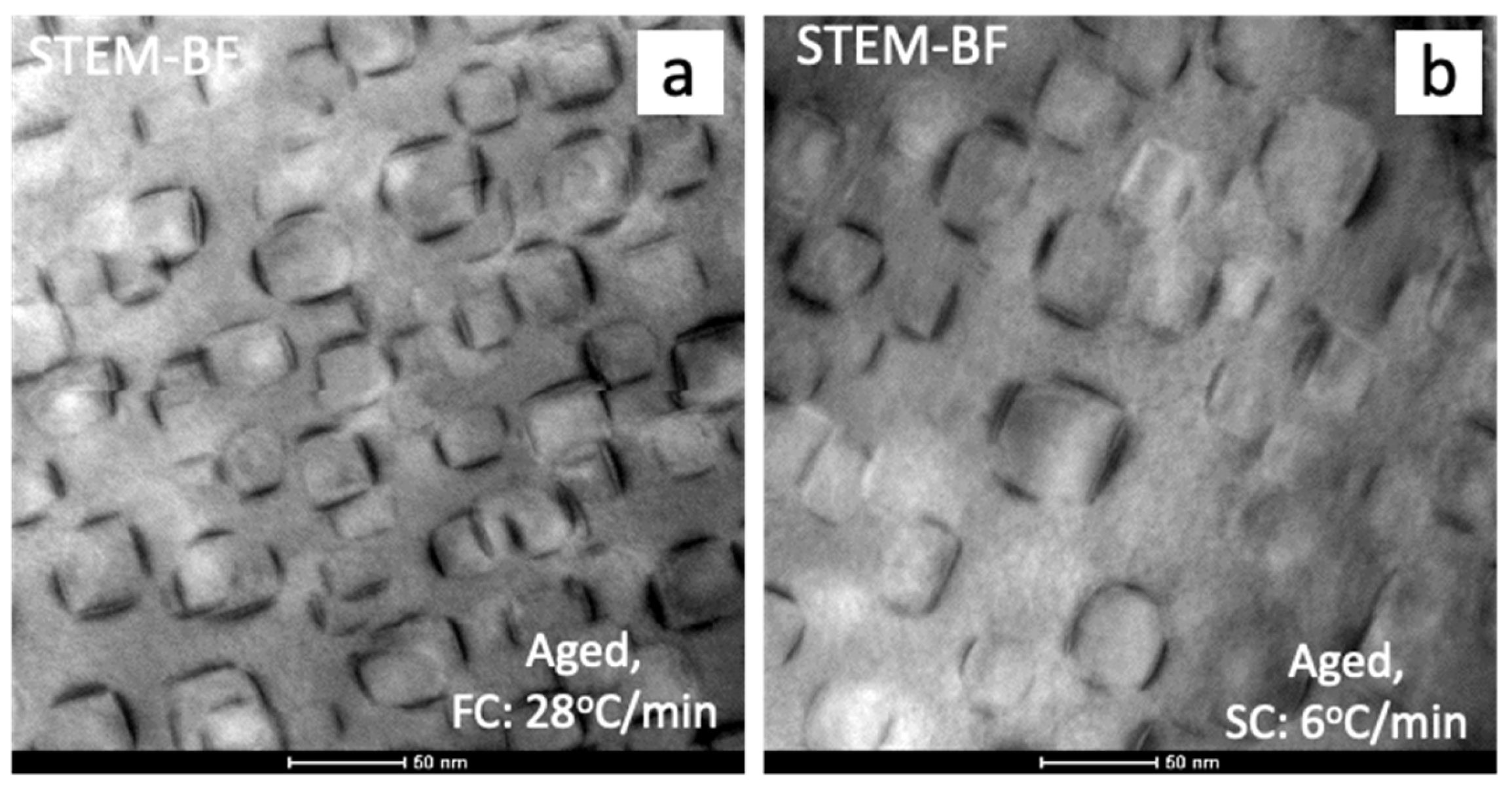
3.1. Aged Microstructural Characterization
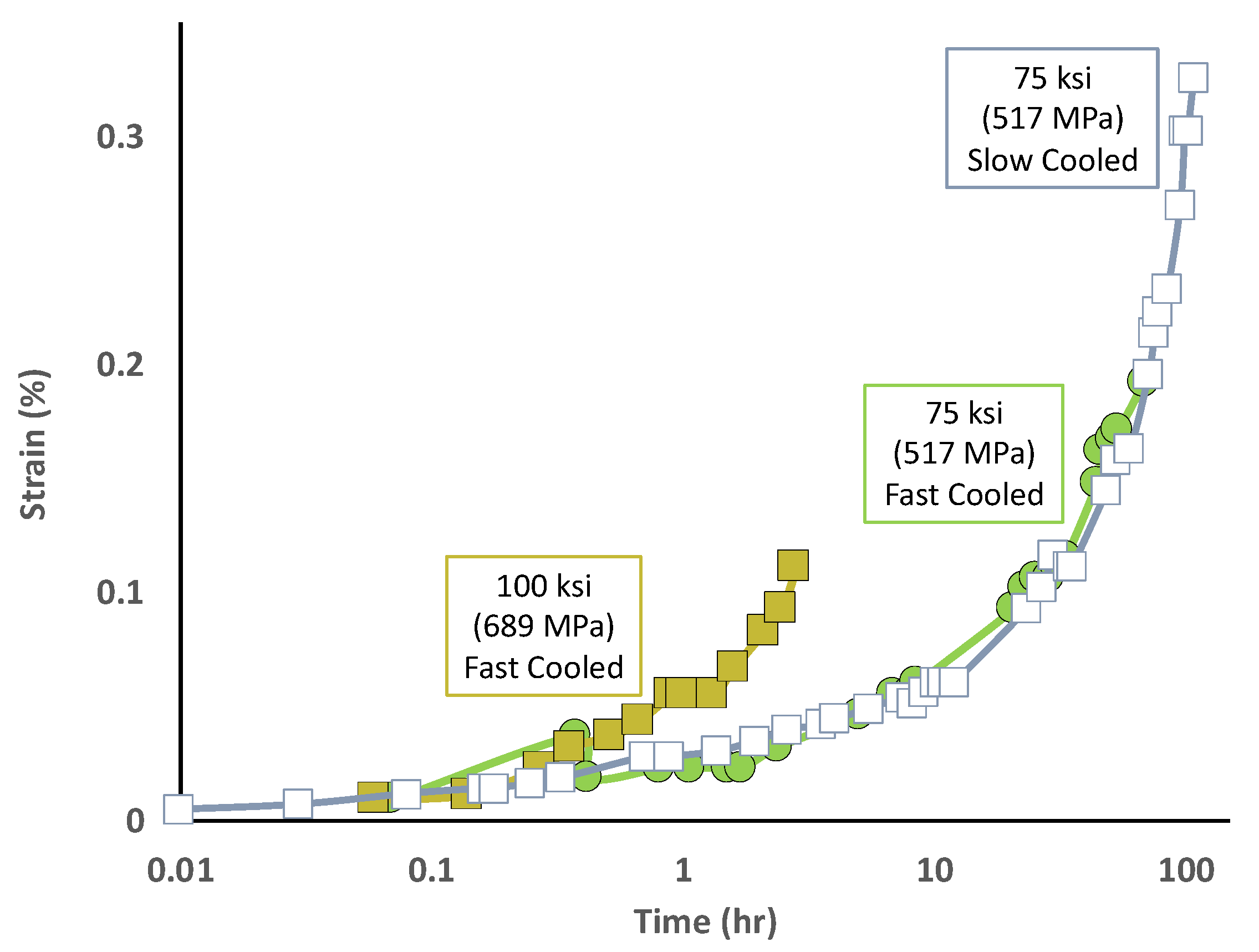
The microstructure of aged IN718-27 subjected to 28 °C/min cooling after solution treatment (IN718-27 FC) was studied using BSE imaging and STEM-EDS (Figure 2) mapping. The average grain size of the alloy is 70 μ m . The grains appear almost equiaxed with a high density of annealing twins (Figure 2a). There are few carbide precipitates with an average diameter of 4 μ m (encircled in Figure 2a), which are speculated to be MC-type carbides based on previous reports [3,10,11]. Moreover, these carbide precipitates appear bright in the SEM BSE micrograph (Figure 2a), indicating that they are rich in Nb.
At a higher magnification, the grains appear to consist of two distinct types of precipitates, as demonstrated by the variation of contrast in the SEM BSE image (Figure 2b). The precipitates exhibiting a darker contrast than the background are γ - γ coprecipitates (referred as coprecipitates from here on). On the other hand, the brighter precipitates near grain boundaries are presumably δ precipitates, which is consistent with several reports on conventionally processed (air-cooled) IN718 [12,13,14]. The coprecipitates appear to be uniformly distributed within the grains. However, a coprecipitate free zone is evident in the proximity of the grain boundary. This result is unsurprising, since both the δ phase and the coprecipitates compete for Nb. Thus, the presence of the δ phase at the grain boundaries depletes some of the Nb from the surrounding γ matrix. Subsequently, coprecipitate nucleation is hindered in this region near the grain boundaries.
At an even higher magnification, STEM-EDS mapping confirms that the coprecipitates observed in the grain interiors exhibit the intended compact morphology (Figure 2c). The map shows elemental distribution of Al (in green) and Nb (in red). While the γ phase is rich in Al, the γ phase is predominantly Ni3Nb-based. Thus, the EDS map of composite Nb and Al elemental segregations indicate the respective phases and successfully reveal the compact morphology of the γ - γ coprecipitates. The γ precipitate, which forms the core of compact coprecipitates, is between 20–60 nm in size. On the other hand, the γ discs exhibit thicknesses and lengths of 5 nm and 50 nm, respectively. Overall, the coprecipitates are about 20–60 nm in size. A detailed TEM-based characterization presentation is presented in Appendix A.
Finally, the grain boundary microstructure, acquired using SEM and STEM EDS is presented in Figure 2b,d. All the high angle grain boundaries are decorated by Nb-rich precipitates about 300 nm in length (encircled in Figure 2b). Although the grain boundaries appear clean and straight at lower magnification (Figure 2a), the acicular Nb-rich precipitates lend them a modulating morphology (Figure 2b). However, the sample exhibits a low volume fraction of the grain boundary precipitates (Figure 2b).
Figure 3 presents the grain boundary precipitates present in the aged FC IN718-27 alloy. From Figure 3b,c, it is clear that there are two precipitates present along the high angle grain boundary. While the δ precipitates exhibit an overall composition of Ni3(Nb, Fe, Cr, Al, Ti), the other precipitate (highlighted in orange) appears to be Cr-Mo-Fe rich. Based on a preliminary analysis of HR-STEM micrographs presented in Figure 3d, the Ni3(Nb, Fe, Cr, Al, Ti) phase is expected to be δ and the Cr-Mo-Fe phase is expected to be σ .
Figure 4 compares the microstructure of aged IN718-27 alloys in SC and FC conditions. The microstructure of slow cooled (or SC, 6 °C/min) and aged IN718-27 is very similar to the relatively fast cooled (or FC, 28 °C/min) sample. However, the aged FC sample has slightly finer compact coprecipitates (25–40 nm) as compared to the aged SC sample (40–60 nm). The overall compact coprecipitate volume fraction of both the alloys appears to be very similar. As shown in Figure 4, the microstructure of both the aged FC and SC samples comprises of about 25% of compact coprecipitates exhibiting very similar sizes. This further complements previously published microstructural characterization of a single step aged SC IN718-27 alloy [7]. Note that this alloy does not exhibit compact coprecipitates prior to the aging treatment when subjected to either of the cooling rates after solutionizing. However, both a single-step age at 1400 °F (760 °C) for 8 h, as well as a two-step age (Figure 1), is sufficient to promote unimodal coprecipitates between 20–60 nm in size in IN718-27, irrespective of the cooling rate [7]. Thus, the microstructure of the alloy appears to be insensitive to cooling rates as well as specific aging treatments.

3.2. Creep Tests

Constant load uniaxial tensile creep tests conducted on two-step aged FC and SC IN718-27 at 1200 °F (649 °C) are summarized in Figure 5. Aged IN718-27 FC was tested at two stress levels—100 ksi (689 MPa) and 75 ksi (517 MPa). However, aged IN718-27 SC was only tested at 75 ksi (517 MPa). Under both the loading conditions, the aged IN718-27 FC samples fail before accumulating 0.2% strain. In fact, at 100 ksi (689 MPa), the sample failed in less than 3 h at 0.1% strain. However, at lower stress (75 ksi or 517 MPa), the sample ruptured in 68 h (0.19% strain). Finally, the apparent creep exponent for IN718-27 FC at 1200 °F (649 °C) was calculated by manipulating the Norton creep law equation [15]:
ε ˙ = k σ n
In the above equation, ε ˙ is the creep strain rate, k is a temperature-dependent constant, σ is stress, and n is the stress exponent at a given temperature. In creep experiments, stress exponents between 3 and 8 imply that deformation is controlled by dislocations interacting with obstacles in its path, such as precipitates [16]. The calculated stress exponent for aged IN718-27 FC was found to be 9. High stress exponents, such as this, have frequently been reported for two-phase materials. In superalloys, a higher than expected stress exponent is frequently reported because, in these systems, creep deformation is influenced by an additional internal back stress [17,18].
The aged IN718-27 SC sample was tested at 75 ksi (517 MPa). The sample eventually ruptured after accumulating 0.3% strain in 118 h. Note that, while the creep tests for both the aged IN718-27 FC and SC samples at 75 ksi (517 MPa) concluded different strain levels, the strain vs. time curves appear to overlap (Figure 5). This indicates that, despite the different cooling rates, both the aged samples exhibit similar strain rates at 75 ksi (517 MPa).

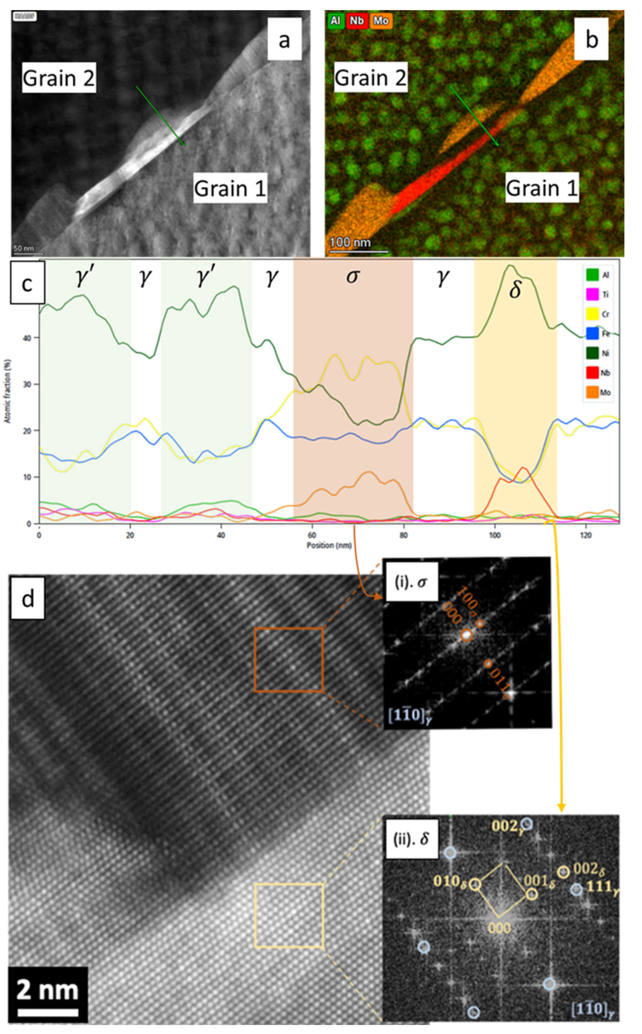
3.3. Analysis of Creep-Deformed Microstructures

Microstructural analyses of two of the deformed samples are presented in Figure 6 and Figure 7. Figure 6 summarizes deformation behavior of the aged IN718-27 FC, sample tested at 100 ksi (689 MPa). This sample failed at 0.11% strain. The loading direction for all the images in Figure 6 is along the viewing direction of the micrograph. The microstructure of the deformed sample exhibits crack formation at grain boundary δ precipitates (Figure 6a). Eventually, such cracks might be expected to coalesce and lead to intergranular failure. In fact, while the fracture surface of this sample indicates mixed mode, intergranular brittle failure is more dominant (Figure 6b). The top surface of the sample, or the fracture plane, appears faceted, implying highly intergranular fracture. In addition, the secondary crack also appears to convey intergranular failure.
Evidence for grain-boundary assisted failure is provided by ECCI, which reveals regions of stress concentrations near grain boundaries and triple junctions (Figure 6c). This is indicated by a bright contrast in these regions. However, most of the grain interior exhibits planar faults. The contrast indicates slip band formation. Traces of potential {111}-type planes for this grain orientation are presented as a schematic at the bottom right of Figure 6c. Note that this grain contains an annealing twin as well. However, for the sake of brevity, the trace analysis has only been presented for the parent grain. The two thick lines in the schematic represent traces of potentially active slip systems. Within the grain interior, only one slip system is active. However, an additional active slip system may be observed in the vicinity of grain boundaries. A second slip trace is observed which is parallel to the annealing twin boundary. In Figure 6d, the slip in a different grain is characterized at a higher magnification. This grain exhibits two faults—marked as 1 and 2 in the Figure 6d. In the case of 1, the precipitate within the slip band appears to be sheared and exhibiting isolated stacking faults. The stacking faults cause the sheared precipitates to appear brighter than the background. However, in case of 2, both the precipitates and the matrix appear to exhibit a brighter contrast, indicating a continuous stacking fault. However, the occurrence of such faults is very low in the investigated sample, and much strain accumulation is observed at the grain boundaries (Figure 6c).
In summary, the fracture surface of the IN718-27 FC sample, creep deformed at 1200 °F (649 °C) and 100 ksi (689 MPa), exhibits extensive intergranular failure. Further ECCI-based characterization of the deformed specimen indicates that even though the calculated apparent stress exponent for this material is 9, ECCI results indicate that deformation is highly assisted by grain boundary structure.
A second SEM-based experiment was undertaken to study the deformed IN718-27 SC sample (Figure 7). Because the sample was deformed at a lower stress of 75 ksi (517 MPa), it fractured after accumulating over 0.3% strain. Figure 7 shows longitudinal sections from the deformed sample. The faceted shape of the fracture surface (Figure 7a) indicates intergranular fracture. Secondary cracks appear to traverse along grain boundaries. In Figure 7b, grains farther below the fracture surface show various stages of void nucleation and coalescence along grain boundaries. The grain interiors, however, show significantly more contrast variations (Figure 7c,d). The grain interior exhibits only one active slip system in this case as well. However, in this sample, a much higher fraction of slip bands is present. Another difference from Figure 6c,d is indicated by the absence of stress concentration pockets near grain boundaries. At a higher magnification, the precipitates contained within slip bands have been sheared and exhibit stacking faults (Figure 7d). However, the stacking fault does not appear to be extending to the γ channels between the coprecipitates. For example, the planar fault traversing from the bottom left to the top right of the micrograph shows isolated faulted coprecipitates. Isolated faults have been frequently reported for air-cooled IN718 containing non-compact coprecipitates, deformed under similar conditions [19,20,21,22,23]. Further, across this micrograph, several dislocation loop/debris like features are visible. However, the contrast from various sources in the microstructure make further analyses complicated. This material will be studied in greater detail using STEM and TEM based characterization techniques and the results will be subsequently communicated.
Overall, the characterization of two deformed samples strained to different levels enabled a brief comparison of the creep mechanisms. Both the samples fail in an intergranular mode. Both exhibit cracks near grain boundary δ precipitates. Moreover, both suggest slip and planar fault formation within their grains. However, in the sample tested at a higher stress level, deformation appears to be more concentrated in pockets near the grain boundary. On the other hand, the IN718-27 SC sample shows bands of isolated stacking faults.

4. Discussion

Our results suggest that in slow-cooled IN718-27, a two-step aging treatment successfully generated compact coprecipitates. Further analyses suggest that the developed microstructure complements the findings of Detor et al. [7]. Detor et al. have reported that IN718-27 does not exhibit compact coprecipitate morphology when cooled at 6 °C/min (SC) or 28 °C/min (FC) after solution treatment. However, a subsequent single-step aging treatment in IN718-27 SC subsequently resulted in compact coprecipitates [7]. This reported compact coprecipitate distribution is in very close agreement with our present findings on IN718-27 FC. Consequently, we conclude from our results that a full-scale turbine disk made of IN718-27 would exhibit a relatively homogeneous compact coprecipitate microstructure.
This compact coprecipitate microstructure is desirable because the compact morphology exhibits superior thermal stability [8,24]. While isolated γ precipitates and non-compact coprecipitates exhibit significant stress-assisted coarsening, compact coprecipitates show negligible coarsening under stress [25,26,27,28]. In fact, the compact coprecipitates have been shown to resist coarsening more than a thousand hours at 1200 °F (649 °C) [24].
This superior stability is generally explained based on the alloy composition of compact coprecipitate containing alloys. This is partially because the compact coprecipitates exhibit delayed transformation of γ precipitates to δ phase [29,30]. Compact coprecipitate formation in an alloy demands that its three major ratios: (Al + Ti)/Nb, Al/Ti and (Al + Ti + Nb) be increased [7,9,29]. A consequence of higher (Al + Ti)/Nb and Al/Ti ratios is a sluggish γ δ reaction at high temperatures. Ultimately, resistance to γ δ transformation also suggests higher overall thermal stability.
However, despite the superior thermal stability of the novel compact morphology, the alloy exhibits poor resistance to creep deformation at 1200 °F (649 °C). The results indicate that IN718-27 exhibits a rupture life of less than 3 h during uniaxial constant stress creep tests at 100 ksi (689 MPa). In comparison, rupture life of conventionally processed and air-cooled (cooling rate >28 °C/min) IN718 is 200 h at 100 ksi [27]. Note that the IN718 discussed in [27] showed transgranular failure, while the aged IN718-27 FC/AC exhibit intergranular failure. Moreover, reports suggest that in similar γ - γ precipitate containing alloys, a slower cooling rate generally increases high temperature strength as well as rupture life [31,32] However, creep behavior of the developed alloy contradicts these reports. In fact, all the reports on creep behavior suggest that air-cooled IN706 and IN718-type alloys containing compact coprecipitates are always outperformed by conventional IN706 or 718, respectively [26,32,33,34,35,36]. This is consistent with our results, where the aged IN718-27 in both AC and FC conditions rupture at much lower strains than air-cooled and aged IN718 at 1200 °F (649 °C).
An obvious reason behind this poor creep performance could be the size of compact coprecipitates. The size of coprecipitates in the present work is about 70 nm. In comparison, the average γ precipitates in aged air-cooled IN718 are between 17–21 nm in diameter [37]. Note, the volume fraction of compact coprecipitates is similar to γ precipitate volume fraction in conventionally processed IN718. Another reason for the performance might be related to the grain boundary structure in the developed alloys. In conventionally processed IN718, grain boundary δ phase precipitates may significantly influence the active deformation mechanism under creep loading [18,26,37,38,39]. Evidence supporting δ -phase assisted deformation in the present work is provided by the observation of creep voids at δ precipitates (Figure 6a and Figure 7c). In fact, creep voids can be observed in the sample after only 0.1% strain accumulation. This is nonintuitive since grain boundary precipitation in IN718 is often encouraged to promote serrated grain boundary structures. This serrated grain boundary structure is known to impede grain boundary cracking under creep conditions. Hence, further studies are required to investigate the deformation behavior of the developed alloy, with a special emphasis on the role of grain boundary precipitates.
In summary, irrespective of the cooling rate (6 °C/min or 28 °C/min), aged IN718-27 exhibits a relatively uniform distribution of compact coprecipitates. The creep behavior of the alloy was studied at 1200 °F (649 °C). Despite the compact coprecipitates, the alloy ruptured around 0.1% and 0.3% strains under 100 ksi (689 MPa) and 75 ksi (517 MPa), respectively. Fractured samples exhibit intergranular failure. Under 100 ksi (689 MPa) loading, the sample shows extensive void formation near grain boundary δ precipitates. Within the grains, slip bands exhibiting isolated stacking faults within the compact coprecipitates were observed. Thus, compact-coprecipitation strengthened alloys, such as IN718-27, need to be further developed to improve their grain boundary character. This is because, although the compact coprecipitates possess superior thermal resistance, the weak grain boundaries in the aged alloy cause premature failure under creep. Subsequently, addition of grain boundary strengtheners (C, B, Zr) as well as refractory metals may need to be explored to improve overall grain boundary strength and crack resistance.

5. Conclusions

A coarsening resistant Ni-base superalloy (IN718-27) was investigated in detail to develop a novel high-temperature turbine disk material. Due to its size, a full-scale land-based turbine disk experiences a range of cooling rates even when quenched.
Irrespective of the cooling rate (6 °C/min or 28 °C/min), aged IN718-27 samples exhibit a relatively uniform distribution of compact coprecipitates.
The tensile creep response at 1200 °F (649 °C) and 75 ksi (517 MPa) for samples with both cooling rates are very similar, indicating an insensitivity to cooling rate. Creep under 75 ksi (517 MPa) loading leads to rupture at 0.3% strain, while under 100 ksi (689 MPa) load, the alloy fails around 0.1% strain.
Fractured samples exhibit intergranular failure. Moreover, all the crept samples show extensive void formation near grain boundary δ precipitates.
Deformed grain interiors in the 75 ksi (517 MPa) creep deformed sample show slip bands with frequent shearing of co-precipitates and formation of planar faults within the particles.
Our results indicate that compact coprecipitation strengthened superalloys, such as IN718-27, exhibit an insensitivity to cooling rates, which allows their microstructures to be thermally stable. Thus, these IN718-variant alloys could potentially replace current turbine disk materials for use at higher temperatures. However, aged IN718-27 also exhibits lower creep strength and prematurely fails at 1200 °F (649 °C) due to grain boundary precipitates. Thus, while this novel class of compact coprecipitation-strengthened superalloys shows some promise, significant improvements are needed before it can be considered as a next-generation turbine disk material. To that end, first, their grain boundary character must be improved. Next, the intragranular microstructure might also require further optimization.

Author Contributions

Conceptualization, R.D., A.J.D., Y.W. and M.J.M.; methodology, C.H.Z.; investigation, S.M., C.H.Z., R.D., A.J.D. and R.W.H.; formal analysis, S.M. and H.S.; writing—original draft preparation, S.M.; writing—review and editing, S.M., C.H.Z., Y.W., G.B.V., R.D., R.W.H. and M.J.M.; visualization, S.M.; resources, R.D. and A.J.D.; supervision, G.B.V., Y.W. and M.J.M.; funding acquisition, M.J.M. and Y.W. All authors have read and agreed to the published version of the manuscript.

Funding

This material is based upon work supported by the Department of Energy under Award No. DE-FE0031278. Additional support for S.M., Y.W. and M.J.M. provided by the NSF DMREF program DMR—1922239.

Institutional Review Board Statement

Not applicable.

Informed Consent Statement

Not applicable.

Data Availability Statement

The data presented in this study are available on request from the corresponding authors.

Acknowledgments

C.H.Z. acknowledges funding by the Alexander von Humboldt Foundation (AvH) through a Feodor Lynen Research Fellowship. Electron microscopy was performed at the Center for Electron Microscopy and Analysis (CEMAS) at The Ohio State University.

Conflicts of Interest

The authors declare no conflict of interest.

Appendix A

Figure A1. TEM analysis of aged FC IN718-27 alloy showing compact coprecipitates and γ variants using (a) TEM-BF and (c,d) DF microscopy. (b) presents the indexed SAD pattern showing two variants of γ marked as 1 and 2. DF micrographs using spots 1 and 2 are presented in (c,d), respectively.
Metals 11 01897 g0a1
Figure A1 presents TEM characterization of the developed aged FC alloy. The two dark field images (Figure A1c,d) show two of the three γ variants present in this grain.

References

  1. GE Gas Power. Breaking the Power Plant Efficiency Record Again. Available online: https://www.ge.com/gas-power/resources/articles/2018/nishi-nagoya-efficiency-record (accessed on 20 September 2021).
  2. Kellner, T. Here’s Why the Latest Guinness World Record Will Keep France Lit up Long after Soccer Fans Leave. GE News. 17 June 2016. Available online: https://www.ge.com/news/reports/bouchain (accessed on 22 September 2021).
  3. Keiser, D.D.; Brown, H.L. Review of the Physical Metallurgy of Alloy 718; Idaho National Engineering Lab.: Idaho Falls, ID, USA, 1976. [Google Scholar]
  4. Singh, A.R.P.; Nag, S.; Hwang, J.Y.; Viswanathan, G.B.; Tiley, J.; Srinivasan, R.; Fraser, H.L.; Banerjee, R. Influence of cooling rate on the development of multiple generations of γ′ precipitates in a commercial nickel base superalloy. Mater. Charact. 2011, 62, 878–886. [Google Scholar] [CrossRef]
  5. Klepser, C.A. Effect of continuous cooling rate on the precipitation of gamma prime in nickel-based superalloys. Scr. Metall. Mater. 1995, 33, 589–596. [Google Scholar] [CrossRef]
  6. Qiu, C.L.; Andrews, P. On the formation of irregular-shaped gamma prime and serrated grain boundaries in a nickel-based superalloy during continuous cooling. Mater. Charact. 2013, 76, 28–34. [Google Scholar] [CrossRef]
  7. Detor, A.J.; DiDomizio, R.; Sharghi-Moshtaghin, R.; Zhou, N.; Shi, R.; Wang, Y.; McAllister, D.P.; Mills, M.J. Enabling Large Superalloy Parts Using Compact Coprecipitation of γ′ and γ″. Metall. Mater. Trans. A 2018, 49, 708–717. [Google Scholar] [CrossRef]
  8. Shi, R.; McAllister, D.P.; Zhou, N.; Detor, A.J.; DiDomizio, R.; Mills, M.J.; Wang, Y. Growth behavior of γ′/γ″ coprecipitates in Ni-Base superalloys. Acta Mater. 2019, 164, 220–236. [Google Scholar] [CrossRef]
  9. Cozar, R.; Pineau, A. Morphology of y′ and y″ precipitates and thermal stability of inconel 718 type alloys. Metall. Mater. Trans. B 1973, 4, 47–59. [Google Scholar] [CrossRef]
  10. Sundararaman, M.; Mukhopadhyay, P.; Banerjee, S. Carbide Precipitation in Nickel Base Superalloys 718 and 625 and Their Effect on Mechanical Properties. In Proceedings of the Superalloys 718, 625, 706 and Various Derivatives (1997), TMS, Pittsburgh, PA, USA, 15–18 June 1997; pp. 367–378. [Google Scholar]
  11. Mitchell, A.; Schmalz, A.J.; Schvezov, C.; Cockroft, S.L. The Precipitation of Primary Carbides in Alloy 718. In Proceedings of the Superalloys 718, 625, 706 and Various Derivatives (1994), TMS, Pittsburgh, PA, USA, 26–29 June 1994; pp. 65–78. [Google Scholar]
  12. Hassan, B.; Corney, J. Grain boundary precipitation in Inconel 718 and ATI 718Plus. Mater. Sci. Technol. 2017, 33, 1879–1889. [Google Scholar] [CrossRef] [Green Version]
  13. Bor, H.-Y.; Wei, C.-N.; Nguyen, H.T.; Yeh, A.-C.; Kuo, C.-M.; Box, P.O. Aging Effects on the γ′ and γ″ Precipitates of Inconel 718 Superalloy. In Proceedings of the 7th International Symposium on Superalloy, Pittsburgh, PA, USA, 10–13 October 2010. [Google Scholar]
  14. Kuo, C.-M.; Yang, Y.-T.; Bor, H.-Y.; Wei, C.-N.; Tai, C.-C. Aging effects on the microstructure and creep behavior of Inconel 718 superalloy. Mater. Sci. Eng. A 2009, 510, 289–294. [Google Scholar] [CrossRef]
  15. Norton, F.H. The Creep of Steel at High Temperatures; McGraw-Hill Book Company, Inc.: New York, NY, USA, 1929. [Google Scholar]
  16. Mills, M.; Daehn, G. Dislocation-Mediated Time-Dependent Deformation in Crystalline Solids. In Computational Methods for Microstructure-Property Relationships; Ghosh, S., Dimiduk, D., Eds.; Springer: Boston, MA, USA, 2011; pp. 311–361. ISBN 978-1-4419-0643-4. [Google Scholar]
  17. Evans, R.W.; Wilshire, B. Creep of Metals and Alloys; Institute of Metals: London, UK, 1985. [Google Scholar]
  18. Chen, W.; Chaturvedi, M.C. The effect of grain boundary precipitates on the creep behavior of Inconel 718. Mater. Sci. Eng. A 1994, 183, 81–89. [Google Scholar] [CrossRef]
  19. Zenk, C.H.; Feng, L.; McAllister, D.; Wang, Y.; Mills, M.J. Shearing Mechanisms of Co-Precipitates in IN718. Acta Mater. 2021, 220, 117305. [Google Scholar] [CrossRef]
  20. McAllister, D.; Lv, D.; Deutchman, H.; Peterson, B.; Wang, Y.; Mills, M.J. Novel Characterization of Deformation Mechanisms in a Ni-base Superalloy Using HAADF Imaging and Atomic Ordering Analysis. Microsc. Microanal. 2016, 22, 272–273. [Google Scholar] [CrossRef] [Green Version]
  21. McAllister, D.; Lv, D.; Feng, L.; Deutchman, H.; Wessman, A.; Wang, Y.; Mills, M.J. Characterization and Modeling of Deformation Mechanisms in Ni-Base Superalloy 718. In Proceedings of the 9th International Symposium on Superalloy 718 & Derivatives: Energy, Aerospace, and Industrial Applications; Ott, E., Liu, X., Andersson, J., Bi, Z., Bockenstedt, K., Dempster, I., Groh, J., Heck, K., Jablonski, P., Kaplan, M., et al., Eds.; Springer: Cham, Switzerland, 2018; pp. 319–338. [Google Scholar]
  22. McAllister, D.; Lv, D.; Peterson, B.; Deutchman, H.; Wang, Y.; Mills, M.J. Lower temperature deformation mechanisms in a γ″-strengthened Ni-base superalloy. Scr. Mater. 2016, 115, 108–112. [Google Scholar] [CrossRef]
  23. Feng, L.; McAllister, D.; Zenk, C.H.; Mills, M.J.; Wang, Y. Deformation Mechanisms of γ′ and γ″ Co-precipitates in IN718. In Proceedings of the Superalloys 2020; Tin, S., Hardy, M., Clews, J., Cormier, J., Feng, Q., Marcin, J., O’Brien, C., Suzuki, A., Eds.; Springer: Cham, Switzerland, 2020; pp. 669–679. [Google Scholar]
  24. Andrieu, E.; Wang, N.; Molins, R.; Pineau, A. Influence of Compositional Modifications on Thermal Stability of Alloy 718. In Proceedings of the Superalloys 718, 625, 706 and Various Derivatives (1994), Pittsburgh, PA, USA, 26–29 June 1994; pp. 695–710. [Google Scholar]
  25. Dong, J.X.; Xie, X.S.; Zhang, S.H. Enhancements of thermal structure stability in a Ni-Base superalloy. Scr. Metall. Mater. 1993, 28, 1477–1482. [Google Scholar] [CrossRef]
  26. Andrieu, E.; Cozar, R.; Pineau, A. Effect of Environment and Microstructure on the High Temperature Behavior of Alloy 718. In Proceedings of the Superalloys 718 Metallurgy and Applications (1989), Pittsburgh, PA, USA, 12–14 June 1989; pp. 241–256. [Google Scholar]
  27. Molins, R.; Andrieu, E.; Pineau, A. Overaging, Deformation and Rupture Micromechanisms of Alloy 718 in Relation to Notch Creep Rupture Strength. In Proceedings of the Superalloys 718, 625 and Various Derivatives (1991), Pittsburgh, PA, USA, 23–26 June 1991; pp. 589–602. [Google Scholar]
  28. Qin, H.; Bi, Z.; Zhang, R.; Lee, T.L.; Yu, H.; Chi, H.; Li, D.; Dong, H.; Du, J.; Zhang, J. Stress-Induced Variant Selection of γ″ Phase in Inconel 718 During Service: Mechanism and Effects on Mechanical Behavior. Miner. Met. Mater. Ser. 2020, 713–725. [Google Scholar] [CrossRef]
  29. Collier, J.P.; Wong, S.H.; Tien, J.K.; Phillips, J.C. The effect of varying AI, Ti, and Nb content on the phase stability of Inconel 718. Metall. Trans. A 1988, 19, 1657–1666. [Google Scholar] [CrossRef]
  30. Collier, J.P.; Selius, A.O.; Tien, J.K. On Developing a Microstructurally and Thermally Stable Iron-Nickel Base Superalloy. In Proceedings of the Superalloys 1988 (Sixth International Symposium), TMS, Pittsburgh, PA, USA, 18–22 September1988; pp. 43–52. [Google Scholar]
  31. Onyewuenyi, O.A. Alloy 718: Alloy Optimization for Applications in Oil and Gas Production. In Proceedings of the Superalloys 718 Metallurgy and Applications (1989), TMS, Pittsburgh, PA, USA, 12–14 June1989; pp. 345–362. [Google Scholar]
  32. Shibata, T.; Takahashi, T.; Shudo, Y.; Kusuhashi, M.; Taira, J.; Ishiguro, T. Effect of Cooling Rate from Solution Treatment on Precipitation Behavior and Mechanical Properties of Alloy 706. In Proceedings of the Superalloys 718, 625, 706 and Various Derivatives (1997), TMS, Pittsburgh, PA, USA, 15–18 June 1997; pp. 379–388. [Google Scholar]
  33. Guo, E.; Xu, F.; Loria, E.A. Effect of Heat Treatment and Compositional Modification on Strength and Thermal Stability of Alloy 718. In Proceedings of the Superalloys 718, 625 and Various Derivatives (1991), TMS, Pittsburgh, PA, USA, 23–26 June 1991; pp. 389–396. [Google Scholar]
  34. Guo, E.; Xu, F.; Loria, E.A. Improving Thermal Stability of Alloy 718 via Small Modifications in Composition. In Proceedings of the Superalloys 718 Metallurgy and Applications (1989), TMS, Pittsburgh, PA, USA, 12–14 June 1989; pp. 567–576. [Google Scholar]
  35. Guo, E.; Xu, F.; Loria, E.A. Comparison of f/y″ Precipitates and Mechanical Properties in Modified 718 Alloys. In Proceedings of the Superalloys 718, 625 and Various Derivatives (1991), Pittsburgh, PA, USA, 23–26 June 1991; pp. 397–408. [Google Scholar]
  36. Guo, E.; Xu, F.; Loria, E.A. Further Studies on Thermal Stability of Modified 718 Alloys. In Proceedings of the Superalloys 718, 625, 706 and Various Derivatives (1994), Pittsburgh, PA, USA, 26–29 June 1994; pp. 721–734. [Google Scholar]
  37. Chen, W.; Chaturvedi, M.C. Grain Boundary Dependent Creep Behaviour of Inconel 718. Can. Metall. Q. 1993, 32, 363–367. [Google Scholar] [CrossRef]
  38. Chen, W.; Chaturvedi, M.C. Dependence of Creep Fracture of Inconel 718 on Grain Boundary Precipitates. Acta Mater. 1997, 45, 2735–2746. [Google Scholar] [CrossRef]
  39. Takahashi, T.; Ishiguro, T.; Orita, K.; Taira, J.; Shibata, T.; Nakata, S. Effects of Grain Boundary Precipitation on Creep Rupture Properties of Alloys 706 and 718 Turbine Disk Forgings. In Proceedings of the Superalloys 718, 625, 706 and Various Derivatives (1994), TMS, Pittsburgh, PA, USA, 26–29 June 1994; pp. 557–565. [Google Scholar]
Figure 1. Schematic of heat treatment: solution treatment at 1800 °F (982 °C) was followed by a two-step age. Two cooling rates (6 °C/min and 28 °C/min) were used to simulate the cooling rate variations in a full-scale turbine disk forging.
Metals 11 01897 g001
Figure 2. Microstructural characterization of aged IN718-27FC: (a,b) SEM BSE micrographs showing the overall grain structure, and precipitate distribution within a grain, respectively; (c,d) STEM EDS maps acquired along <100>-type zone axis showing compact coprecipitates and grain boundary precipitates, respectively. (c-inset) diffraction pattern confirming γ and γ phases.
Metals 11 01897 g002
Figure 3. Grain boundary precipitates observed in aged FC IN718-27 alloy. (a) HAADF (CL = 73 mm) micrographs showing grain boundary precipitates, (b) STEM EDS map from the same region as in (a) highlighting regions of Al, Nb and Mo enrichment in green, red and orange; (c) composition vs distance plot along the green arrow in (b); (d) High resolution STEM (HR-STEM) HAADF micrograph showing different atomic ordering present in the two grain boundary precipitates. This is further confirmed by the two patterns in the inset (i) and (ii) obtained through fast fourier transform (FFT) of the corresponding regions in the HR-STEM micrograph.
Metals 11 01897 g003
Figure 4. Compact coprecipitation microstructure in IN718-27 aged samples prepared by (a) fast cooling and (b) slow cooling. Both the images were acquired along [100] zone.
Metals 11 01897 g004
Figure 5. Summary of tensile creep test results for aged IN718-27 FC & SC. Tests were carried out at 1200 °F (649 °C) in air.
Metals 11 01897 g005
Figure 6. SEM-based characterization of IN718-27 FC crept at 1200 °F (649 °C) and 100 ksi (689 MPa) till it fails at 0.11% strain in 2.3 h. (a) Microvoids originating at the incoherent δ γ interface near a grain boundary. (b) Fracture surface showing intergranular failure. (c,d) ECCI micrographs showing planar faults. The active slip systems are marked for emphasis. (Note that the stress axis is parallel to the viewing direction for all the micrographs).
Metals 11 01897 g006
Figure 7. SEM-based characterization of IN718-27 SC crept at 1200 °F (649 °C) and 75 ksi (517 MPa) till it fails at 0.3% strain after 118 h. This sample was prepared longitudinal to the viewing direction. (a) Fracture surface showing intergranular failure. (b) Various stages of microvoid nucleation and coalescence along grain (c,d) ECCI micrographs showing planar faults. The active slip systems are marked for emphasis.
Metals 11 01897 g007
Table 1. Alloy composition of IN718-27. Typical IN718 composition is included for comparison.
Alloy Name (at.%)NiCrFeAlTiNbMoC
71851.921.219.61.11.13.21.80.1
718-2751.820.719.52.31.12.71.80.1
Publisher’s Note: MDPI stays neutral with regard to jurisdictional claims in published maps and institutional affiliations.

