Article

High-Pressure Cooling in Finishing Turning of Haynes 282 Using Carbide Tools: Haynes 282 and Inconel 718 Comparison

by
Antonio Díaz-Álvarez
*,
José Díaz-Álvarez
,
José Luis Cantero
and
María Henar Miguélez
Department of Mechanical Engineering, University Carlos III of Madrid, Leganés, 28911 Madrid, Spain
*
Author to whom correspondence should be addressed.
Submission received: 3 November 2021 / Revised: 24 November 2021 / Accepted: 25 November 2021 / Published: 27 November 2021
(This article belongs to the Special Issue Optimization and Analysis of Metal Cutting Processes)

Abstract

:
Despite the interest of industry in nickel-based superalloys and its main features (high temperatures resistance, hardness, low thermal conductivity, among others), even today they are still materials that are difficult to cut. Cutting tools withstand both high pressures and temperatures highly localized at the cutting area because of the elevated work hardening of the alloy and the problems for the cutting fluid to access the region, with the consequent strong tool wear. The use of cutting fluids at high pressures improves coolant access and heat removal. This paper analyzed the machining of Haynes 282 alloy by means of coated carbide tools under high-pressure cutting fluids at finishing conditions. Tests were developed at different cutting speeds and feeds quantifying the machining forces, surface roughness, tool wear, and tool life. Values of 45.9 min and Ra between 2 µm and 1 µm were obtained in this study for tool life and roughness, respectively, for the combination of cutting speed 50 m/min and feed 0.1 mm/rev. Likewise, a comparative analysis is included with the results obtained in previous works developed by the authors relating to the finishing turning of Haynes 282 and Inconel 718 under conventional pressure cooling. The comparative analysis with Inconel 718 is included in the study due to its importance within the nickel base superalloys being widely used in industry and widely analyzed in scientific literature.

1. Introduction

Nickel-based alloys are widely used in critical parts of jet engines and industrial steam turbines, where about 50% of the components are based on these alloys [1]. Ni alloys are also significant in petrochemical plants, marine equipment, and nuclear reactors, among others [2], leading to great demand of technologies for processing difficult-to-cut materials [3]. Low thermal conductivity, extreme work hardening with high specific cutting force (up to 3000 N/mm2), chemical affinity, and the presence of abrasive carbide particles results in low machinability [4], surface defects [5], and tool wear rates [6].
Within the nickel-based alloys, Inconel 718 is one of the most popular materials in industry; however, Waspaloy and Haynes 282 are other superalloys with enhanced creep behavior gaining acceptance. Furthermore, these alloys (Waspaloy and Haynes 282) show greater resistance to deformation over time, despite having lower values of static mechanical properties and yield stress in comparison to Inconel 718, allowing the increase of service temperature [7]. Moreover, Haynes 282 also offers a better level of weldability and fabricability when compared to superalloys with similar creep strengths [8].
Haynes 282 shows a centered-cubic austenitic lattice, where its strength comes mainly from the precipitation of the grain carbides and γ′ precipitates, Ni3 (Al,Ti) [9]. The content of carbides in this superalloy provides three main functions: firstly, grain boundary carbides allow stress relaxation, and prevent grain sliding or dislocation by means of hardening the grain boundary being barriers when they are properly formed; if carbides precipitate in its structure, there is a strengthening of the material; and finally, the precipitation of grain boundary carbides prevents other elements from modifying the phase during service [10].
During the machining of Haynes 282, its austenitic grains harden quickly, which leads to a high heat rate generated mainly at the cutting edge [11]. This trend, together with the tendency for Haynes to weld on the cutting edge at extreme temperatures and pressures, leads to the appearance of built up edge (BUE) at low cutting speeds. The creation of the BUE is not stable, normally disappearing in the subsequent cuts, resulting in chipping progression and further cracking [12] and catastrophic breaking of the cutting edge [13]. Cutting tool material for Haynes 282 machining should have wear resistance, high toughness and strength, high hot hardness, chemical stability at high temperatures, and good thermal shock properties [2].
The cutting tool recommendations for the turning of nickel-based superalloys at high-speed conditions include coated carbides [14], cubic boron nitride (CBN)/polycrystalline cubic boron nitride (PCBN), and ceramics, whereas uncoated carbide tools are just used at low-speed conditions [15]. Common coatings include PVD-TiAlN or a combination of TiN, AlTiN, and AlCrTiN among others due to its high chemical inertness, high hot hardness (1500 HVV at more than 1000 °C temperature), high oxidation resistance, and less trend to experience BUE [16]. Moreover, moderate cost makes the coated carbide tools suitable for finishing operations on nickel-based superalloys in comparison to more expensive materials, such as ceramics and CBN. (Ti,Al)N is one of the most analyzed coatings because of its relatively easy deposition process on the substrate and cutting performance [17]. The adhesion of aluminum in the TiN coat composition provides enhanced hardness, inertness, and temperature strength resulting in improved cutting behavior [17]. In general, coated carbide tools are recommended at cutting speeds up to 100 m/min during turning of nickel-based alloys [18].
Improving the quality surface and limiting tool wear progression during machining of Ni superalloys involve a great challenge, strongly related to dismissing temperature around the cutting zone. Different advanced methods such as cryogenic cooling [19], high pressure water jet, and solid lubricants among others have been reported in the literature [20]. However, high pressure cooling is a more conventional technique related to significant improvement in the machining of difficult-to-cut materials.
At present, environmental currents have reached the manufacturing processes, becoming a problematic aspect due to the increasingly strict regulations on waste, polluting emissions, as well as health problems for workers [21]. Thus, although it is necessary to optimize and improve manufacturing processes, it is also necessary to increase efforts in order to minimize the impact of industrial activity on health and the environment [22]. During machining, cutting fluids reduce the friction at the tool-chip area; help in the chip removal from the cutting area; and reduce both the tool and workpiece temperature [23]. During machining, two different types of coolant are commonly used, straight and neat oils, both based on mineral oils and additives to enrich its properties [24]. These chemical components react during the process of machining with the cutting tool and the workpiece generating waste pollutants hazardous to human health and the environment [25], such as chlorides and sulfides [24]. Moreover, coolant systems management account for up to 17% of the total production costs, being inefficient in many cases acting far from the areas of maximum temperature [26]. Techniques such as minimum quantity lubrication (MQL) [27] or minimum quantity cutting fluids (MQCF) [28] are increasingly used when machining superalloys, allowing a significant reduction in cutting fluids and improved efficiency when compared to conventional systems [29]. High-pressure cutting fluid (HPJC) application is also a suitable technique reducing waste and avoiding aggressive conditions involved in dry conditions in absence of cutting fluid. On the other hand, it should be considered that the use of HPJC can cause problems in the machining of certain industrial components. For example, the high pressure could induce undesirable chatter during machining a low-stiffness part. This situation would make it necessary to modify the cooling conditions (injection pressure or direction of the coolant) or if this is not possible, it would force the use of conventional pressure cooling. HPJC creates a turbulent flow promoting heat dissipation at both the tool and the workpiece. In conventional cooling, the cutting fluid reaching the cutting area comes into contact with hot zones, boiling and generating a decrease in efficiency [1]. However, using high pressure [30], the coolant is able to penetrate the boiling layer and increase heat dissipation [31]. Good results have been obtained by the combination of HPJC and high-speed rotary ultrasonic elliptical milling (HRUEM) in which the tool wear mode of adhesive wear was able to be significantly inhibited [32].
At present, there are several articles that analyze the use of HPJC during machining in nickel-based superalloys, and few studies focus on the Haynes 282.
Tamil Alagan et al. [33] studied the effect of HPJC in the flank and Ranke faces of WC tool on the tool wear mechanism and process conditions in the turning of Inconel 718. They carried out facing tests with a round cement uncoated carbide tool at 45 and 90 m/min of cutting speed and 0.2 mm/rev of feed. Thus, they found an increase of tool life by means of using low cutting speeds with maximum available pressure for both rake and flank. In a more recent study [34], the authors analyzed the HPJC and the chip morphology in turning Inconel 718. They found that increments on the pressure from 8 to 16 MPa, resulted in a decrease on the mean contact area by 13–28% for all pressures at both cutting speed tested. Moreover, at low cutting speed and pressure, the contact area decreased. Khochtali et al. [35] studied the tool wear during the machining of Inconel 718 under both conventional and high-pressure coolant. They tested two different cutting speeds of 35 and 45 m/min setting that the lubrication improves the chip fragmentation, lower forces generation, and higher tool life when the results were compared between conventional and high-pressure coolant (up to 110% and 76% at a cutting speed of 35 and 45 m/min, respectively).
Díaz-Álvarez et al. [23] analyzed machining of Haynes 282 with coated carbide tools under dry conditions. They found that the best dry conditions (in terms of tool wear) were low cutting speed (50 m/min) with no significant influence of the feed. Moreover, tool life decreased up to 85% when cutting speed increased from 50 m/min to 70 m/min at 0.1 mm/rev feed. In terms of roughness, they found low values, ranging from 0.7 to 2.5 µm. The same authors, Díaz-Álvarez et al. [36], studied finishing turning of Haynes 282 with TiAl/TiAlN carbide tools under conventional coolant pressure. Tool life was found to be very sensitive to the cutting speed, especially when it ranged between 50 and 70 m/min for feeds of 0.1 and 0.15 mm/rev obtaining 15-33 min of cutting-edge durations, respectively. The roughness ranged from 1.8 to 2.6 µm, being lower with the wear progression (0.7–1.5 µm). Moreover, BUE, chipping, flank, and notch wear were the main wear mechanisms observed during tests. Suárez et al. [10] analyzed the cutting forces and tool wear during the turning of Haynes 282 under high-pressure coolant. They found a decrease on the cutting forces for all conditions tested with 80 bar high pressure cooling. Nevertheless, despite this decrease in the forces, no reduction in tool wear was observed. The most important contributions in the machining of Haynes 282 to date are summarized in Table 1.
The aim of this work is to improve the knowledge concerning machinability of Haynes 282 using high-pressure coolant, given that to date, there is just one previous study that analyzed the process under one cutting speed and feed through uncoated carbide tools. Thus, in this work, cutting forces, tool wear, and roughness was analyzed during the turning of Haynes 282 at three different cutting speeds and feeds under high-pressure coolant by means of coated carbide tool. Moreover, the results obtained during the study were compared to the scarce data existing in the literature for the conventional process. In this sense, the results are also related to those obtained by the same authors in Inconel 718 machining. It is possible to find information regarding the mechanical properties of Haynes 282 alloy compared to other nickel-based superalloys such as Waspalloy. However, there is a lack of comparative information with the Inconel 718. Static mechanical properties and yield stress of Inconel 718 being slightly better than Haynes 282 is due to its structure gamma-double-prime (γ′′). However, Inconel 718 presents a faster weakening at high temperatures when compared to Haynes 282, this fact being influent on the enhanced difficulty of Haynes 282 machining when compared to Inconel 718 [37].
This work is divided into three sections: in Section 2, the materials and tools used in the tests are described, as well as the setup of the machine and the cutting conditions tested; in Section 3, the main results obtained in relation to cutting forces, wear, and tool life, as well as roughness, are analyzed; finally, in Section 4, the main conclusions of the study carried out are summarized.

2. Experimental Setup

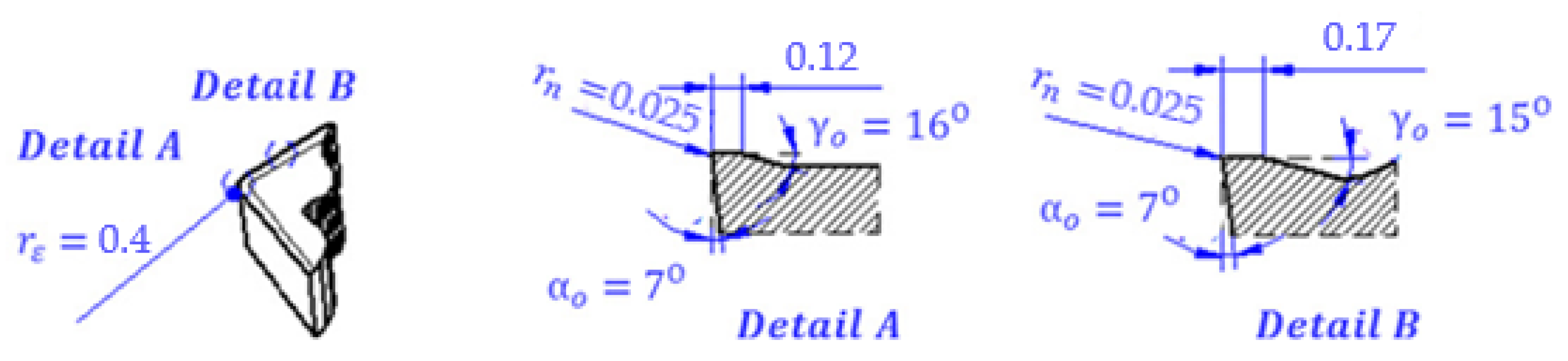
2.1. Workpiece Material and Cutting Tools

Haynes 282 workpieces of 90 mm diameter shape manufactured in accordance with the AMS5951 standard were used for the turning tests. Values of hardness ranged between 42.2 and 43.5 HRc as average (several points were taken along the length of the workpiece) and were measured for each sample. Haynes 282 alloy used in the turning tests was annealed at 1135 °C, this being the typical temperature for this thermal treatment in the range between 1121 and 1149 °C, and subsequently aged hardened in two stages of heating and cooling in air (1283 °C for 2 h and 1061 °C for 8 h). In Table 2, the elements percentages of the Haynes 282 used in the turning tests are summarized.
The Inconel 718 turning tests used as a reference for comparison have been described in detail in [38]. Cylindrical workpieces of 100 mm in diameter and 130 mm in length were used, and hardened by solution treatment and aging, which corresponded to homogeneous hardness in the material of 44–45.5 HRc.
TiAl/TiAlN coated carbide inserts provided by SECO (SECO Tools, Barcelona, Spain) were used. The insert (CCMT 09T304F1), specially aimed at high-speed finishing turning of nickel-based alloys, was tested in fresh conditions for each test carried out. The insert had nose angle 80°, rake angle 16°, relief angle 7°, and nose and honing radius of 0.4 mm and 25 µm, respectively (see Figure 1). SECO also provided the tool holder for the insert chosen which is the model SCLCR 2525M09JET.

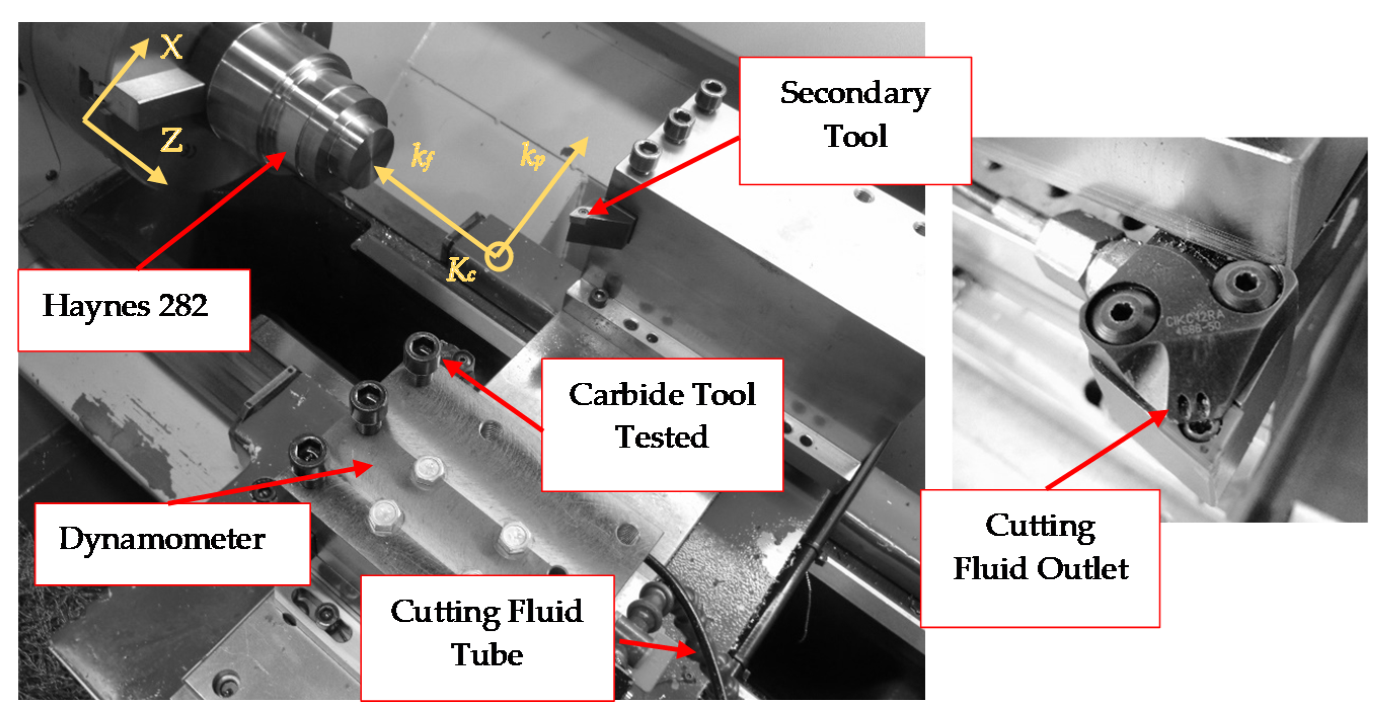
2.2. Instrumentation and Setup

Machining tests were executed in a Pinacho lathe (Pinacho, Huesca, Spain) equipped with a Kistler 9257B dynamometer and a multichannel charge amplifier (Kistler 5070A, Kistler, Winterthur, Switzerland) mounted together to simultaneously record while testing the cutting forces in three main cutting directions corresponding to the feed force axis, the back force axis, and the cutting axis. The values quantified during each test were stored in a computer by a data acquisition system. Figure 2 shows the experimental set up and main components used during the turning tests. Based on the information in the dynamometer calibration certificate, it was estimated that the measurement uncertainty is between 1% and 2%.
During each test, a rounded surface that corresponds to the nose radius of the tool was left at the end of the pass; it was necessary to remove it before the next test in order to avoid the increase of undeformed cross section of the chip that is generated [38]. This amount of material at the end of the pass, as consequence of tool nose radius in a finishing operation involving small depth of pass, may suppose meaningful increments in cutting forces and therefore influence tool wear progression. In order to avoid this phenomenon, a secondary tool was used for removing the increment on the material derived from the nose radius of the main tool between subsequent tool passes (see Figure 2).
A stereo microscope Optika SZR (Optika, Ponteranica, Italy) was used to periodically evaluate the tool wear level for each condition tested. Moreover, in order to analyze the wear evolution, SEM (scanning electron microscopy) images have been obtained with a microscope Philips XL-30 (Philips, Amsterdam, Netherlands). The surface quality of the workpiece was evaluated in terms of roughness measured by means of Mitutoyo SJ-201 (Mitutoyo, Tokyo, Japan). The roughness values presented in this study were obtained as the mean of nine measurements taken at different angular positions of the machined surface. In all cases, for each test condition considered, measurements with variations of less than 5% were obtained. The measurement uncertainty of the surface finish equipment is significantly lower than these variations (less than 1%).
A Rhenus FU50T (water-soluble) cutting fluid with a 6% of mixing ratio was used in the turning tests [38]. The solution was introduced in the turning lathe externally using a Smart Cooling System (Duo Jetstream Tooling from Seco Tools, Barcelona, Spain) able to control the cutting fluid pressure. Turning tests were developed with a cutting fluid pressure of 70 bar. A comparative analysis of the results using high pressure cooling with those obtained in the Haynes 282 turning tests [36] and Inconel 718 [38] with cooling at 7.5 bar (conventional pressure) was carried out and is presented in the following sections.
Moderate cutting parameters are recommended for turning Haynes 282 with cutting speeds in the range 30–35 m/min, feeds 0.1–0.18 mm/rev, and depth of cut 1 mm as stablished in [39]. In previous works of the authors [23,36], improved values of cutting parameters were reached when turning Haynes 282 under conventional pressure and dry conditions using coated carbide tools: cutting speed ranged from 50 to 90 m/min, feeds between 0.1 and 0.15 mm/rev, and a depth of 0.25 mm obtaining tool lives of 33 and 30 min, respectively. The cutting parameters imposed in the current finishing turning tests of Haynes 282 with high-pressure cooling were set at the values summarized in Table 3, the same used in with conventional pressure cooling in order to compare results [36]. The cutting tests with Inconel 718 with conventional pressure cooling [38] were carried out for the same parameters corresponding to cutting speed 50 and 70 m/min, but did not include tests with cutting speed 90 m/min.

3. Results and Discussion

3.1. Cutting Forces

The progression of the machining forces components, feed force (Ff), cutting force (Fc), and back force (Fp), was measured for each test. Fc is the main cutting force acting tangentially to the rotational direction, Ff is the force at the feed direction, and Fp the force at the depth of pass axis. In addition, the resultant force (Fr) is the vectorial sum of the main cutting force (Fc), feed force (Ff), and back force (Fp). Each test was performed twice to ensure the repeatability of the results, obtaining deviations when they were compared to the mean value lower than 5% with respect to the mean value; therefore, for further analyses, the mean value obtained through the average of 5 measurements in the stable force zone was chosen. In order to see the effect of the cutting speed, three speeds and three feeds were selected, analyzing possible trends. Comparative analysis of the forces were based on the kc, kf, kp, and kr (specific force components) quantified by means of the ratio between each force component and the cross-sectional area values calculated from the technological parameters: feed (f) and depth of cut (ap), see Equation (1) [40].
k i = F i / ( f · a p )
with i = c, f, p. Flank wear, adhesion, or brittle breaks are commonly related to the specific force components.

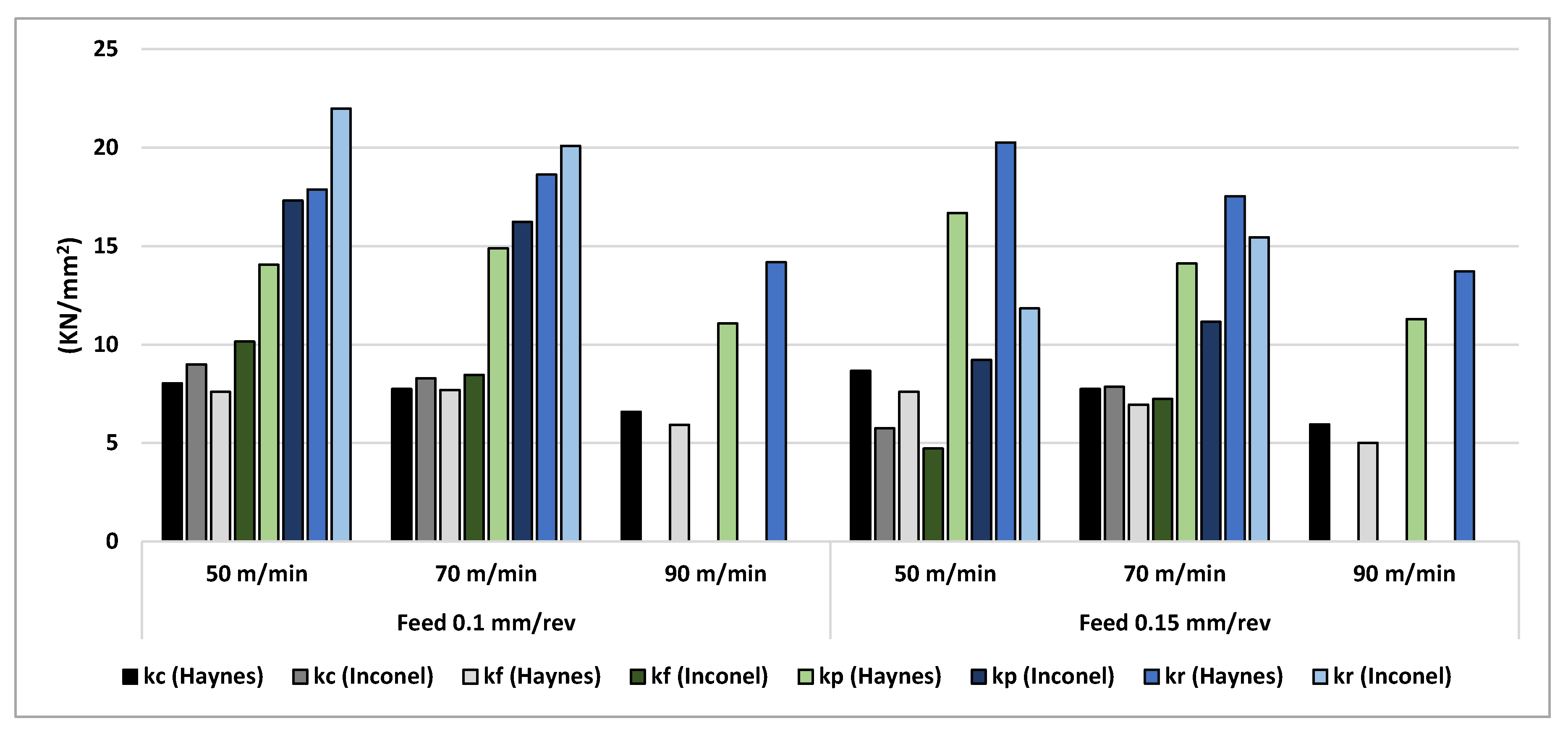
3.1.1. Evolution of the Specific Force Components with Fresh Tools

In Figure 3, the obtained values of kc, kf, and kp forces quantified at the beginning of the Haynes 282 turning tests with high pressure cooling and fresh tools are presented. The results of kc force go from 3600 N/mm2 (case: Vc = 90 m/min and feed = 0.15 mm/rev) to 4400 N/mm2 (case: Vc = 50 m/min and feed = 0.1 mm/rev).
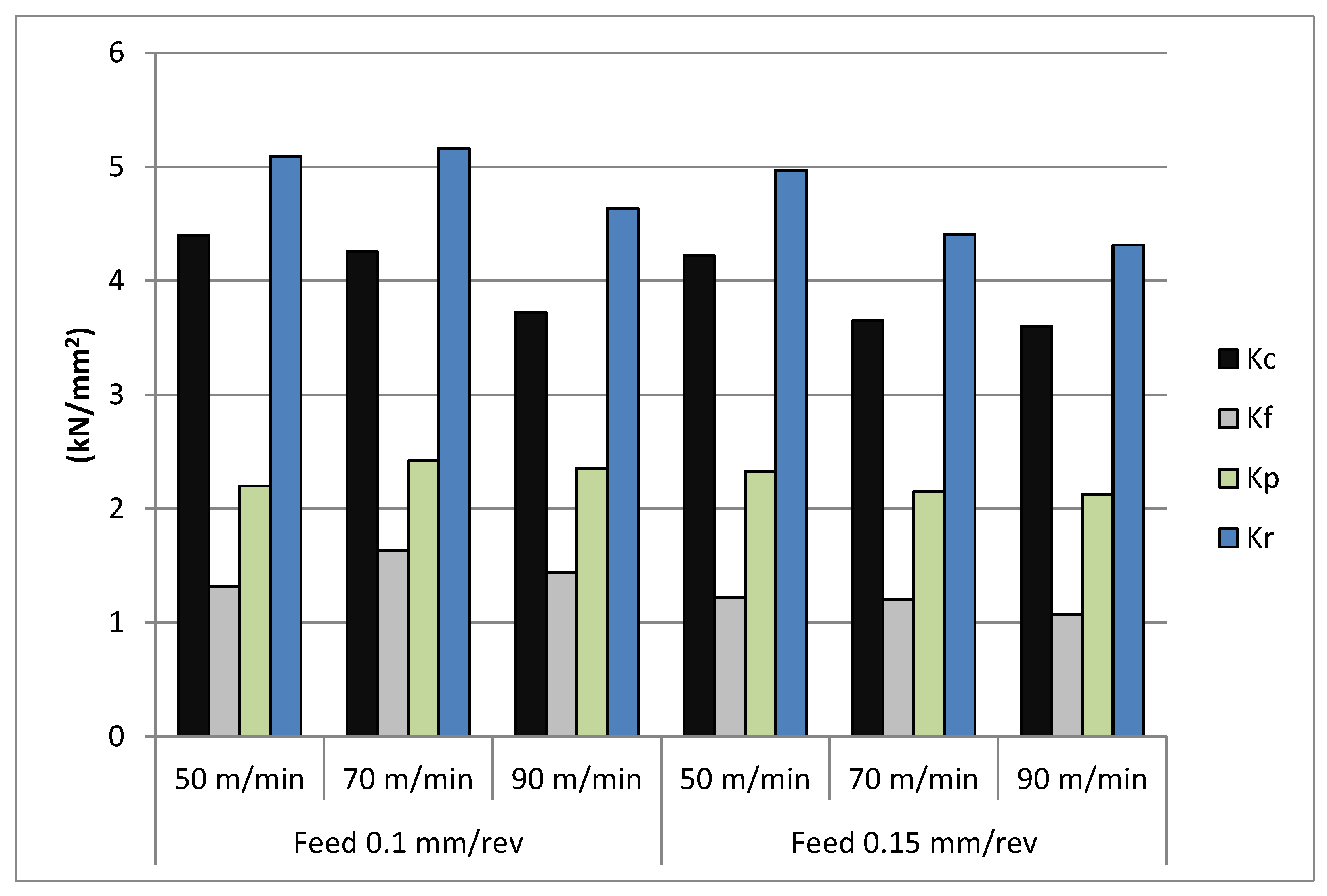
  • For the two feeds considered, it was observed that the component most affected by the variation of the cutting speed was the specific cutting force (kc); this component decreased up to 15 % when the cutting speed was increased from 50 m/min to 90 m/min. By increasing the cutting speed, the material’s temperature to be cut rose resulting in thermal softening of the material and hence lower cutting forces.
  • The remaining specific components of the machining force showed in general variations somewhat smaller than those indicated for kc. In addition, the variations were of the opposite sign depending on the feed. Specifically, for the lowest feed used (0.1 mm/rev), the specific feed force (kf) increased up to 9.1% and the specific back force (kp) up to 7.1% when the cutting speed was increased from 50 to 90 m/min. For the feed equal to 0.15 mm/rev, the values of the specific feed force (kf) and the specific back force (kp) decreased up to 12.5% and 8.7%, respectively.
The components kf and kp are closely related to the ploughing force caused by the material that flows under the cutting edge during machining and that by elastic recovery pushes on the relief surface of the tool. When the cutting speed was higher and the feed was lower (0.1 mm/rev), the ploughing force increased due to the action of the tool on the machined surface in the previous revolutions. Higher thermal expansions appeared, and machining was more affected by work hardening of the material and thermal damage caused by previous revolutions. It was also due to the enhanced effect of the edge geometry for lower feed. These phenomena especially affect the kf and kp components and it is reasonable to expect that they are the cause of the observed change in trend of these components with the cutting speed.
Analysis of the specific cutting forces with feed:
  • Regarding the influence of feed changes over the kc, kf, and kp force components, decrements of up to 14.3% for the kc force, up to 26.4% for the kf force, and up to 11.15% for the kp force were recorded when the feed was increased from 0.1 mm/rev to 0.15 mm/rev. The influence of the feed over the kc, kf, and kp force components was as expected. This effect is due to the larger amount of material exposed to strong deformation along the cutting edge in the case of lower feed.
Regarding the Haynes 282 turning with conventional pressure cooling [36], the values of the resultant specific force, kr, with fresh tool were between 6% and 14% lower than those obtained with high pressure cooling (see Figure 4). The opposite trend was reported in [6] for the machining of other nickel-based superalloys such as Inconel 718 or Waspalloy: when using high-pressure coolant, lower machining forces were obtained due to the better tribological conditions in the tool chip contact. In the case of Haynes 282 machining, the higher forces when using high pressure could be related to the lower thermal softening of the workpiece material. In general, in the case of cooling with conventional pressure, the kf and kp components did not suffer significant variations when modifying the cutting parameters. However, the specific cutting force, kc, decreased when increasing both cutting speed (up to 8% reduction) and feed (10% reduction).
Comparing the specific force components for turning with conventional pressure of Haynes 282 [36] and Inconel 718 [38], values of the specific cutting force (kc) were obtained up to 13% higher for the Haynes alloy. Similar trends and mean values were obtained for both materials.

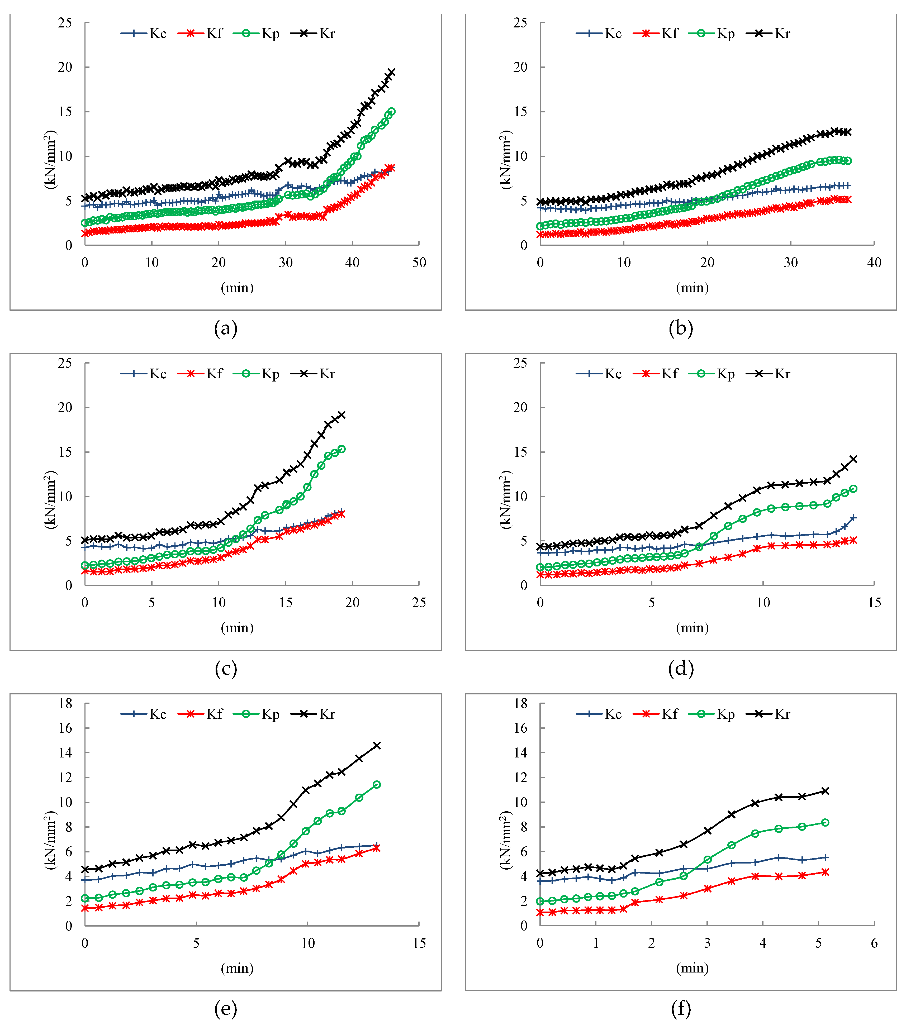
3.1.2. Progression of the Specific Machining Forces with the Cutting Time

The progression of the specific force components in relation to the cutting time is shown in the Figure 5. In all tested conditions, all the kc, kf, and kp force components grew with cutting time. However, the specific cutting force (kc) followed a homogeneous linear increment during the whole tool life while the growth of the specific feed force (kf) and specific back force (kp) components showed two regions with approximately linear growth with different slopes, higher in the second region than in the first one. In all the tested conditions, the kf and kp components had a faster growth with wear, obtaining values of these components for the end-of-life tool between 3 and 6 times higher than those corresponding to the fresh tool. Relative to component kc, tool wear causes smaller increases, between 50% and 100%. The component of the force kp, in addition to its high relative increase with wear, reached absolute values higher than those of the other components of the force, so its evolution may indicate the tool wear level.
The two regions observed in the progression of kc, kf, and kp force components in relation to the cutting time could also be related to the tool wear types that appeared in the turning tests. The beginning of the test could be dominated by a moderate chipping combined to a progressive flank, whereas the subsequent region may be related to more aggressive chipping at the cutting edge and a rapid growth of the notch, influencing the tool integrity and, therefore, the specific feed and back force components. Flank wear and chipping cause a progressive increase in all components of the machining force, but especially in kp and kf, due to the effect of these types of wear on the ploughing force. Notch wear only affects a localized area of the cutting edge corresponding to the end of the depth of pass, so it has reduced effectiveness on machining forces.
In the tests with feed 0.1 mm/rev, there were greater increases in kf and kp than with feed 0.15 mm/rev. Specifically, in the tests with feed 0.1 mm/rev and cutting speed 50 m/min and 70 m/min, the greatest increases of the kf and kp components were produced, reaching values for the tool at the end of its life of around 50% higher than those achieved in the other trials.
As will be described in Section 3.2, the types of wear are similar for both values of feed. However, the corresponding effect on the specific forces will be greater in the tests with feed 0.1 mm, mainly because the brittle breaks of the edge have a reduced amplitude that affects a greater percentage of the chip-tool contact zone for this value of feed. This effect is contrary to the ones obtained by Suárez et al. [10] in which they found no visible relation between cutting forces and tool wear.
In the Haynes 282 and Inconel 718 turning processes with conventional pressure cooling [36,38], the evolution of the forces with the level of wear was similar to that described for the Haynes tests with high cooling pressure (see Figure 6). Tool wear caused elevated increases in all force components, especially relevant for kp and kf (between 4 and 10 times higher than those obtained with fresh tool).
As in the turning tests for the Haynes at high cooling pressure, the Inconel 718 turning with conventional pressure and 0.1 mm/rev feed produced greater kf and kp increases than with 0.15 mm/rev feed. This relationship, also in the case of Inconel, is due to the fact that wear is mainly produced by small brittle breaks of the cutting edge of reduced amplitude, which affect a higher percentage of the chip-tool contact area for 0.1 mm/rev feed. The maximum resultant specific force value, kr, was obtained for the feed 0.1 mm/rev and the minimum cutting speed (50 m/min) was 22 kN/mm2 for the Inconel 718 with conventional pressure cooling and 19.5 kN/mm2 for the Haynes with high pressure cooling.
However, in the Haynes tests at conventional pressure, the opposite trend was observed, with increases in kf and kp higher when using feed 0.15 mm/rev. The explanation is due to the larger size of the edge breaks in the tests with feed 0.15 mm/rev, which causes a greater increase in the specific forces. In these tests, the maximum value of the resultant specific force, kr, was 20 kN/mm2 and was obtained for the feed 0.15 mm/rev and the minimum cutting speed (50 m/min).

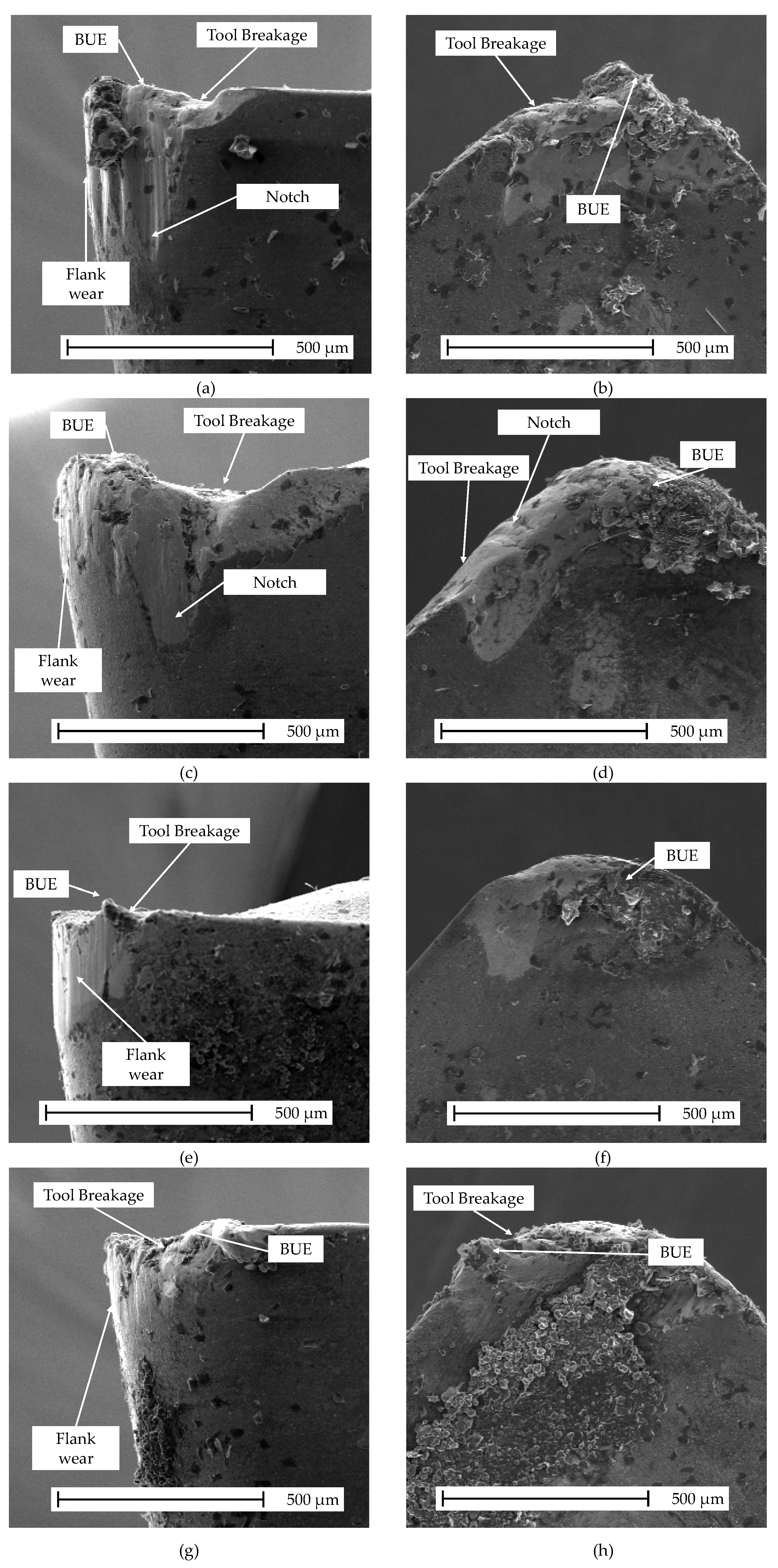
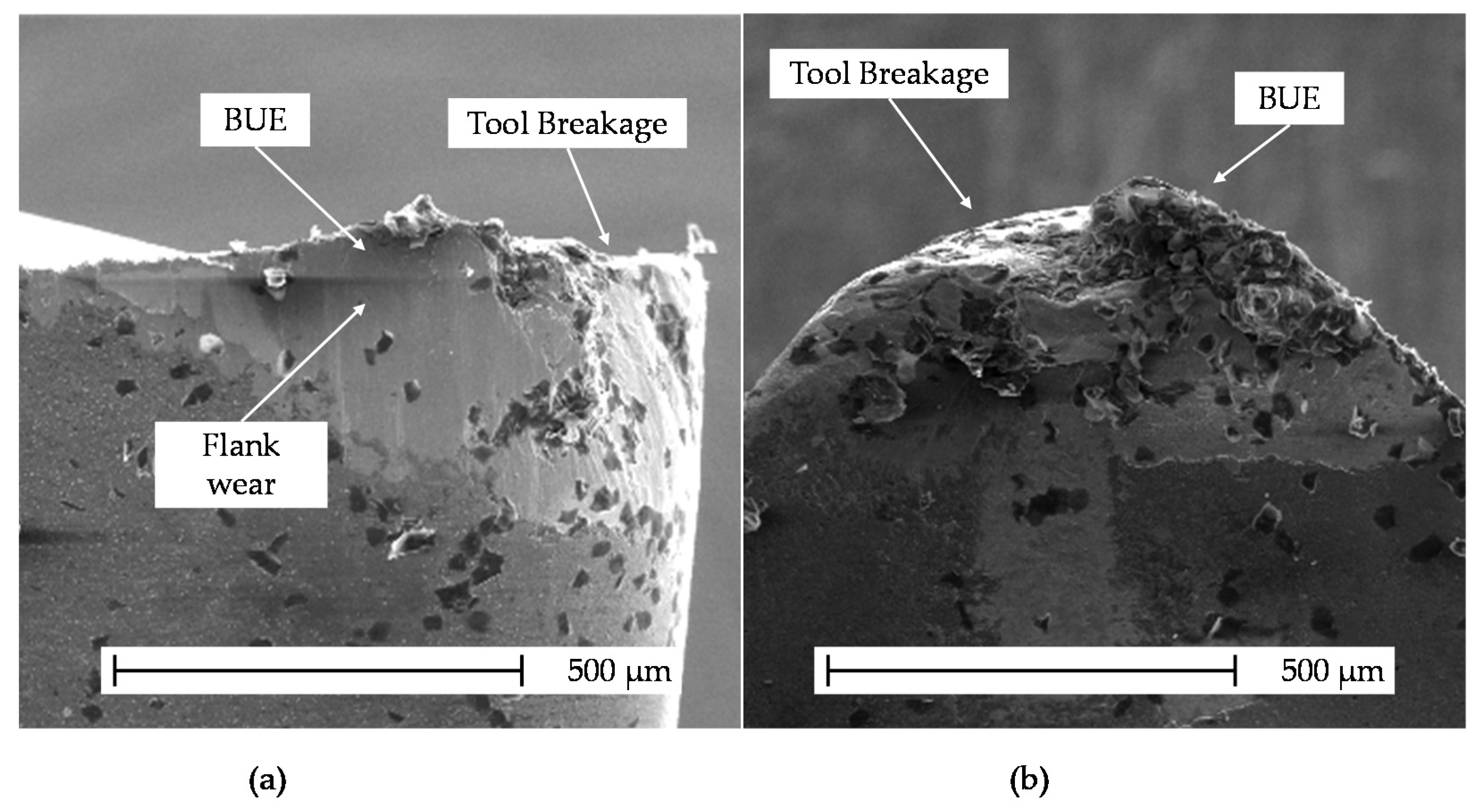
3.2. Analysis of Tool Life and Tool Wear

During each turning test, the level of the tool wear was quantified. Flank, built up edge (BUE), chipping, and notch wear were identified as the main wear types during turning tests. The onset of all wear modes was observed from the first stages of cutting time. Cutting edge catastrophic breakage, or notch and flank wear equal to 0.4 mm, were established as a criterion to state the end of tool life.
During Haynes 282 turning tests with high-pressure cooling and despite all the cutting conditions, material adhesion was observed on all tool’s surfaces, together with BUE formation. Nevertheless, regarding the cutting edge life, this phenomenon was not predominant (see Figure 6).
A severe destruction of the cutting edge was observed at the beginning of the test, for the depth of cut, especially at the relief and rake surface by means of notch wear. Notch wear continues growing and small cutting-edge breakages and flank wear along the whole cutting edge-chip interface (chipping wear) appear for greater cutting times.
For all cutting conditions tested, the catastrophic failure of the cutting-edge pointed out the end of tool life, because of the fragile breakage leading by chipping or by notch wear. These results agree with those obtained by Suárez et al. [10]. In tests at lower cutting speed (50 m/min), notch wear was the dominant type of wear, reaching sizes up to 0.4 mm and causing localized catastrophic failure at the depth of the cutline (see Figure 7a–d). At higher cutting speeds (70 m/min and 90 m/min), the dominant wear was chipping causing deterioration of the non-localized edge and finally the catastrophic breakage of the tool (see images corresponding to cutting speed 90 m/min in Figure 7e–h). Tool life was strongly affected by the faster progression of wear modes, which came through increments on the cutting speed and feed to a lesser extent (see Table 4). Unstable cutting and more higher forces appeared with increments on feed, generating brittle breakages at the cutting edge. The adhesion of material that came from the workpiece appeared mainly by the increase of the temperature at the cutting area [41] through increments of the cutting speed.
Flank wear increased with cutting time following a linear trend. Flank wear progression was more significant for both higher cutting speeds and, to a lesser extent, with feed increments. Nevertheless, a reduction on the flank wear at the last stages of tool life appeared with increments of cutting speed and the feed (See Figure 7), due to the tool failure induced through chipping or notch wear at shorter cutting times. In all the conditions tested, flank wear reached final maximum values in the range 0.25–0.35 mm.
The machined surface per cutting edge (Sedge) and the machined surface per unit time (Smach.t) were used to measure the tool life in relation to the cutting time; its values are summarized for all cutting condition tested in Table 4 through Equations (2) and (3).
S m a c h . t = V c · f · 1000 / 60
S e d g e = S m a c h . t · T · 60
where:
Smach.t: machined surface per unit time (mm2/s)
Sedge: machined surface per edge (mm2)
Vc: cutting speed (m/min)
f: feed (mm/rev)
T: tool life (min)
At the beginning of the tests and for the maximum cutting speed (90 m/min), the wear mode was dominated by means of the chipping, which progressed faster until the end of the tool life due to catastrophic failure being reached (see Figure 7e–h). Tool lives of 6.6 min (feed of 0.15 mm/rev) and 11.5 min (feed of 0.1 m/rev) were obtained for higher feeds in which the progression of the wear was faster.
A contrasting trend was obtained for the medium cutting speed tested (70 m/min), in which the chipping damage appeared later and increased at a lower rate, deriving in catastrophic breakage of the cutting edge (end of tool life) and obtaining tool lives of 19.2 min (feed of 0.1 m/rev) and 14.1 min (feed of 0.15 mm/rev).
Tool lives of 45.9 min (feed of 0.1 m/rev) and 36.8 min (feed of 0.15 mm/rev) were obtained for the lower cutting speed tested (50 m/min), reaching edge breakage with the highest level of notch extension of 0.4 mm; this value was stated as the end of tool life criterion (see Figure 7a–d).
Regarding the cutting times, the maximum tool lives were obtained for the lowest feed and cutting speed (45.9 min) whereas the minimum one corresponded to the higher cutting speed and feed tested (6.6 min). As it was established previously, a decrease in tool lives was obtained for increments in both feed and cutting speed through a faster progression of the chipping damage at the cutting edge. Moreover, a decrease of about 60% and 80% was observed when the cutting speed increased from 50 m/min to 70 m/min and 90 m/min, respectively. Increasing the feed from 0.1 mm/rev to 0.15 m/min resulted in a reduction on the tool life between 20% and 50% (the reduction in the tool life was greater the higher the cutting speed).
Otherwise, the machined surface per cutting edge could be used as a good parameter to control in the industrial efficiency of a tool in finishing operations. Increments up to 20% in the machined surface per cutting edge were obtained for a cutting speed of 50 m/min and a feed of 0.15 mm/rev when compared to the lowest feed. This increase in the machined surface per edge with increasing feed was also observed, although to a lesser extent, for the cutting speed of 70 m/min (increase of 10%). However, in the tests with speed 90 m/min, the increase of the feed produced a reduction of 25% in the machined surface per edge. The increase in the cutting speed reduces the machined surface per cutting edge between 40% and 70% for the two feeds considered.
To determine the appropriate cutting parameters in an industrial process, it must be considered that the duration of the cutting edge presents significant variability, especially when the dominant types of wear are due to brittle breaks. For this reason, it is necessary to properly define tool replacement times including a safety margin, thus it is not practical to use cutting parameters leading to excessively short tool life. In view of the results obtained, it is considered that the industrially viable cutting parameters in the turning of Haynes 282 under high pressure are those corresponding to a tool life greater than 15 min (cutting speed 50 m/min with feeds 0.1 mm/rev or 0.15 mm/rev and cutting speed 70 m/min with feed 0.1 mm/rev). To establish the optimal cutting parameters in a given industrial turning finishing process, a balance should be sought between the machined surface per unit time and the machined surface per cutting edge to obtain moderate production costs. The test with cutting speed 50 m/min and feed 0.1 mm/rev exhibited the longest edge duration (45.9 min). In the test with cutting speed 50 m/min with feed 0.15 mm/rev, the highest machined surface per cutting edge and the highest machined surface per unit time were obtained. In the test with cutting speed 70 m/min with feed 0.1 mm/rev, shorter tool durations and lower values of machined surface per cutting edge were obtained in comparison to the former explained conditions. The machined surface per unit time was intermediate with respect to the values obtained in the tests with cutting speed 50 m/min and feeds of 0.1 mm/rev and 0.15 mm/rev.
Finally, the optimal cutting parameters would be conditioned by the surface quality obtained in the process, an aspect that will be analyzed in the next section.
In the Haynes 282 and Inconel 718 turning processes with conventional pressure cooling [36,38], the evolution of tool wear was very similar. The most important wear types were the same as those described for the turning of Haynes at high coolant pressure: built up edge (BUE), chipping, flank, and notch wear. However, in all conventional pressure turning tests (both Haynes and Inconel), catastrophic tool failure due to chipping was observed (see Figure 8 and Figure 9).
In the test under conventional pressure for Haynes 282, flank and notch wear increased with cutting time at a rate similar to that observed in high-pressure tests. The shorter duration of the tests due to the catastrophic breakage of the tool for shorter cutting times explains why the maximum values of flank and notch wear were in all cases less than 0.25 mm. The maximum tool lives obtained in the Inconel 718 tests were like those obtained in high pressure for Haynes. However, the flank and notch increased at a slower rate in the Inconel tests, so the maximum wear was also kept below 0.25 mm. This result is due to the increased thermal softening of Inconel 718 when compared to Haynes 282.
Table 5 shows the tool life values in terms of cutting time (min) and Sedge (machined surface per edge (mm2)) corresponding to Haynes 282 and Inconel 781 turning with conventional pressure cooling.
The use of high-pressure cooling in the turning of Haynes 282 significantly increased the life of the tool with respect to conventional pressure in the tests at cutting speed 50 m/min. Specifically, the greatest increment occurred in the test at 50 m/min and 0.1 mm/rev, going from a tool life of 33.4 min to 45.9 min (increase of 37%). For cutting speed 50 m/min and feed 0.15 mm/rev, tool life increased from 29.2 to 36.8 min (26% increase). For higher cutting speeds, high pressure cooling resulted in reduced tool life variations, averaging around 2 min. This is due to the fact that in the tests at 70 m/min and 90 m/min the dominant type of wear was the same in the high pressure and conventional pressure tests: breakage due to chipping. These breaks were not reduced by using high pressure, since as noted above, high pressure cooling does not reduce specific machining forces in tests using unworn tools.
The tool life in conventional pressure machining of Inconel 718 and Haynes 282 shows that for the smaller feed (0.1 mm/rev), the tool life was clearly longer in the Inconel tests (43.9 and 25.2 min for Inconel versus 33.4 and 17 min for Haynes at cutting speed of 50 and 70 m/min). However, for 0.15 mm/rev feed, tool life was similar and even longer in Haynes (29.2 and 14.6 min for Haynes versus 24.9 and 14.7 min for Inconel at cutting speeds of 50 and 70 m/min). These results in relation to the duration of the cutting edge are striking because they are opposite to those expected based on the corresponding specific machining forces at the end of tool life. In the tests with feed 0.1 mm/rev, higher specific forces were obtained at the end of tool life when machining Inconel 718 than when machining Haynes 282, while in the tests with feed 0.15 mm/rev, the specific forces at the end of tool life were higher for Haynes 282. Considering that the dominant wear in these tests was edge chipping, it is reasonable to assume that the lower tool lives in Haynes turning with feed 0.1 mm/rev were due to the weakening of the tool due to reaching higher temperatures. These major thermal problems in Haynes with 0.1 mm/rev feed rate are consistent with the fact that the use of high-pressure cooling in Haynes caused a greater increase in edge life during tests with 0.1mm/rev feed in comparison to the tests with feed 0.15 mm/rev.
The cutting parameters considered industrially viable in the Haynes 282 and Inconel 718 turning processes under conventional pressure would be the same indicated for Haynes 282 under high pressure, accounting for a tool life greater than 15 min, that is, cutting speed 50 m/min with feeds of 0.1 mm/rev or 0.15 mm/rev and cutting speed of 70 m/min with feeds of 0.1 mm/rev. It should be noted that in the Haynes 282 tests with both high pressure and conventional pressure, although the longest tool life was obtained with cutting speed 50 m/min and feed 0.1 mm/rev, the highest machined surface per cutting edge corresponded to cutting speed 50 m/min and feed 0.15 mm/rev. However, in the turning tests of Inconel 718, the increase in feed reduced the tool life more so that both the longer edge duration and the maximum machined surface per cutting edge corresponded to cutting speed 50 m/min and feed 0.1 mm/rev.

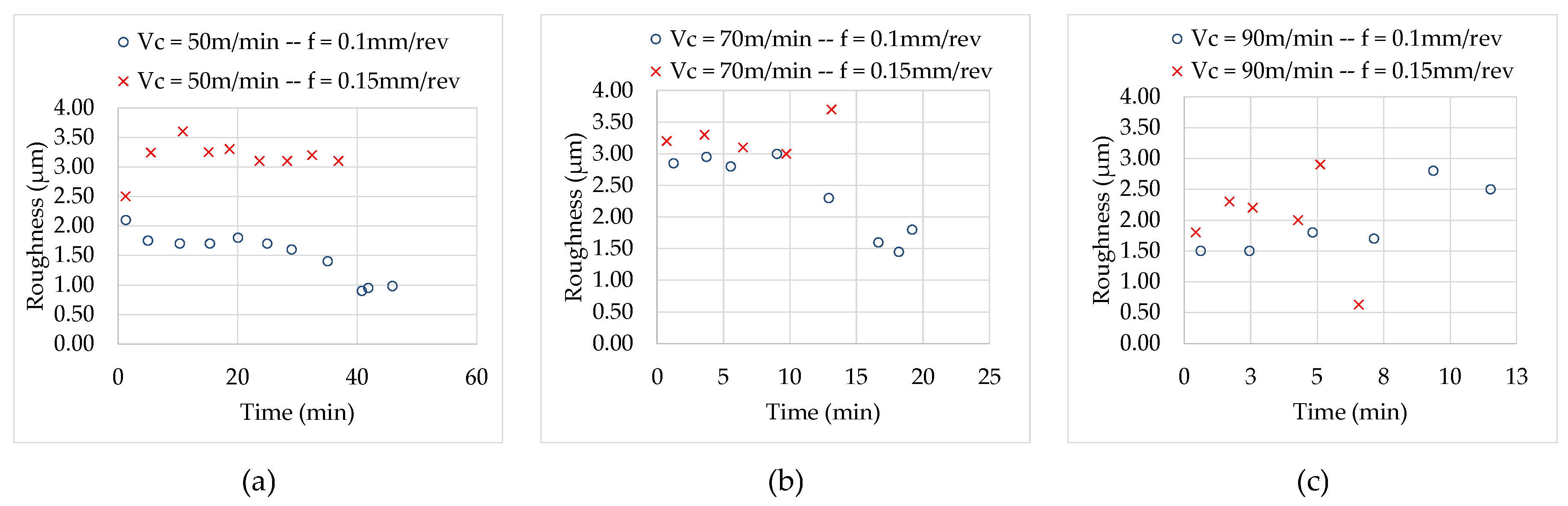
3.3. Analysis of Quality Surface

During several points along the turning tests, the quality of the surface was checked through the arithmetic average roughness (Ra) (see Figure 10). In order to quantify it, values were measured at three different areas, in which a difference lower than 5% between them was obtained. Within those three values of Ra quantified for each condition tested, the highest one was chosen, as it is the most conservative.
At the beginning of the Haynes 282 turning tests with high pressure cooling (fresh tool without significant wear), slightly higher roughness was obtained in the tests with feed 0.15 mm/rev (Ra between 1.8 and 3.2 µm) than in the tests with feed 0.1 mm/rev (Ra between 1.5 and 2.8 µm).
Depending on the cutting parameters, two opposite trends were observed in relation to the effect of tool wear on roughness. In the tests with feed 0.1 mm/rev and cutting speed 50 m/min and 70 m/min, by increasing the cutting time, the roughness was reduced to values of 1 µm and 1.5 µm, respectively. In the remaining conditions tested, the increase in the cutting time was related to higher roughness, reaching Ra values of between 2.5 and 4 µm for the end of tool life. Suárez et al. [10] could not find a clear trend in the roughness mainly due to the size of the grain in its study.
The tests in which the roughness decreased with the cutting time correspond to the conditions for which the increase in the specific back force (kp) and the specific feed force (kf) due to flank wear was clearly higher, reaching end of tool life values around 50% higher than those obtained in the other cutting conditions. These high values of kf and kp caused plastic deformation of the machined surface material, reducing roughness. Moreover, in these tests an increment of the effective tool nose radius was obtained by means of the evolution of the tool wear (see Figure 7b), which may be related to the decrease in roughness values.
As indicated, the optimal cutting parameters in an industrial process would be conditioned by the surface quality obtained. Thus, the surface finishes corresponding to the three cutting conditions with tool durations greater than 15 min and that have therefore been considered industrially viable were analyzed:
  • As indicated, in the test with cutting speed 50 m/min and feed 0.1 mm/rev, the best surface finishes were obtained (Ra between 2 µm and 1 µm).
  • The worst surface finishes were obtained with a cutting speed of 50 m/min and feed 0.15 mm/rev (Ra values higher than 3 µm except in the first passes of the test).
  • In the test with cutting speed 70 m/min and feed 0.1 mm/rev, intermediate surface qualities were obtained with Ra values between 3 µm and 1.5 µm.
Finally, the main aspects related to the surface finish obtained in the turning processes of Haynes 282 and Inconel 718 with conventional pressure cooling [36,38] are highlighted (see Figure 11). At the first stages of the turning tests with fresh tool and without remarkable wear, roughness similar to those obtained in high pressure turning of Haynes 282 were obtained; specifically, slightly higher roughness values in tests with feed 0.15 mm/rev (Ra between 1.7 and 2.5 µm) than in tests with feed 0.1 mm/rev (Ra between 1 and 2.1 µm).
However, for all the tests with conventional pressure, the evolution of the roughness with the level of wear was the same, with a lower roughness being observed with increasing cutting time. Surface finishes at the end of tool life were somewhat better in the Inconel 718 turning tests (Ra between 0.3 µm and 0.8 µm) than in the Haynes 282 tests at conventional pressure (Ra between 0.8 µm and 1.5 µm). The better surface quality with increasing tool wear is explained by the fact that in these tests the evolution of wear derived in an increase of the effective tool nose radius.

4. Conclusions

This work deals with the finishing turning of Haynes 282 under high-pressure cutting fluids, a subject on which there are very few articles to date. In addition, it includes a comparative analysis with Haynes and Inconel 718 conventional-pressure cooling machining. In this paper, different cutting conditions and carbide tools with TiAl/TiAlN coating recommended both for nickel-based superalloys finishing turning were analyzed. The most notable results of this work are detailed below:
  • In general, the application of high-pressure cooling increases tool life but is detrimental in relation to the surface finish obtained. Moreover, surface quality in terms of roughness is worst using high-pressure cooling, which is a disadvantage of this technique.
  • For high-pressure cooling, the best combination of cutting speed 50 m/min and feed 0.1 mm/rev led to the longest edge duration (45.9 min) and the best surface finishes (Ra between 2 µm and 1 µm) were obtained, demonstrating the industrial application of these machining conditions.
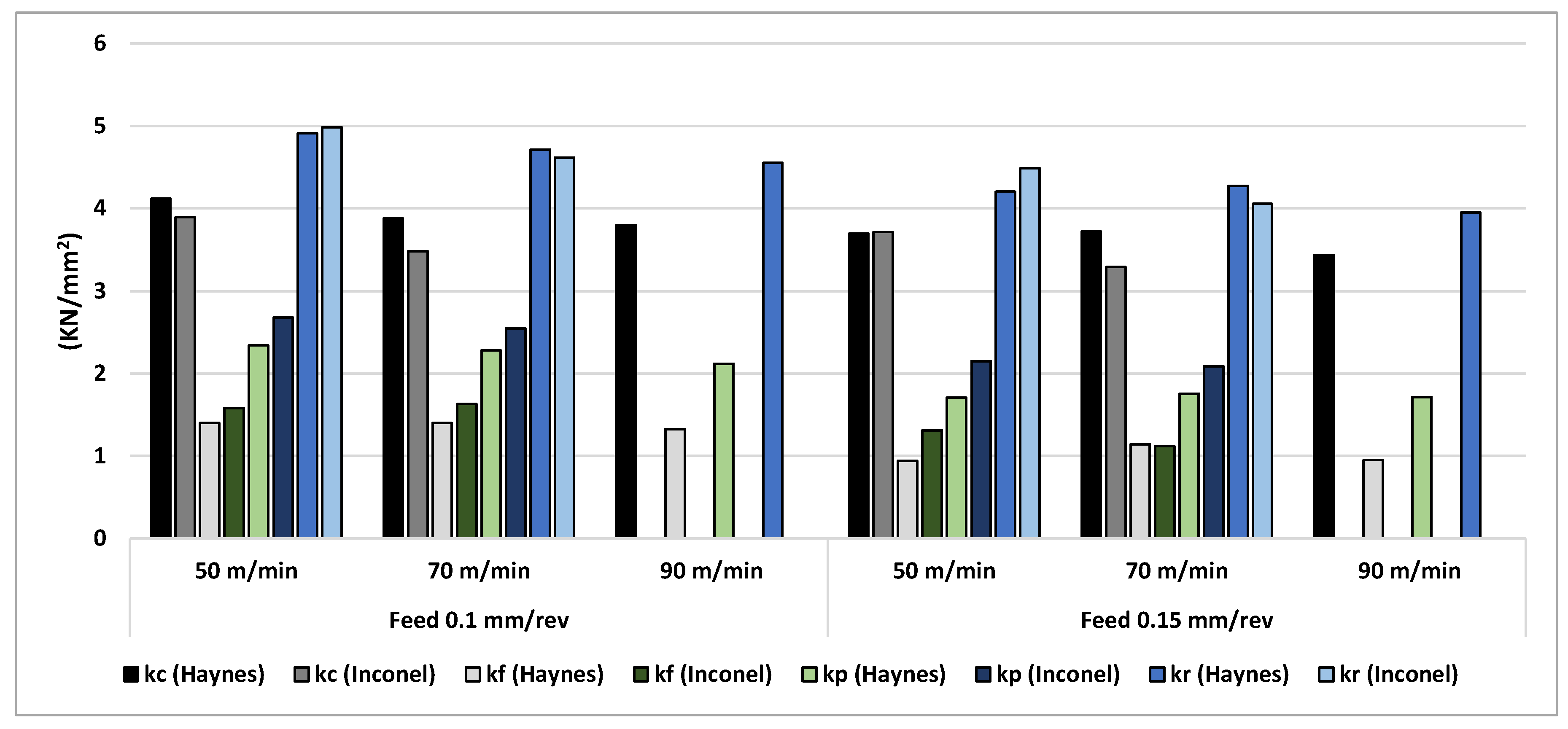
  • The tool life in conventional pressure turning of Inconel 718 and Haynes 282 shows that for the smaller feed (0.1 mm/rev), the tool life is clearly higher in the Inconel tests (43.9 and 25.2 min for Inconel versus 33.4 and 17 min for Haynes at cutting speeds of 50 and 70 m/min). For 0.15 mm/rev feed, tool life is similar and even more elevated in Haynes turning processes.
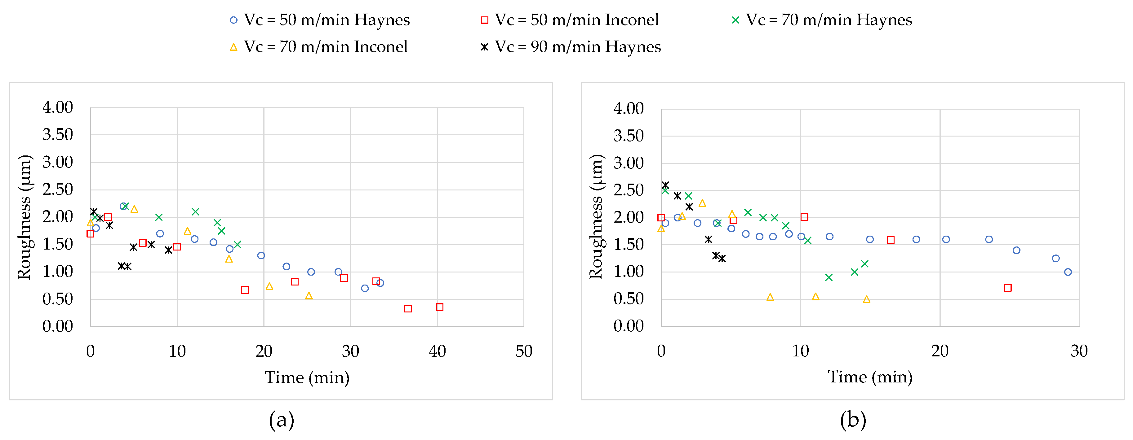
  • The initial surface roughness (obtained with a tool without significant wear) was similar in all the processes considered: turning of Haynes 282 with conventional and high-pressure cooling and Inconel 718 with conventional-pressure cooling, specifically, slightly higher roughness values in tests with feed 0.15 mm/rev (Ra between 1.7 and 3.2 µm) than in tests with feed 0.1 mm/rev (Ra between 1 and 2.8 µm).
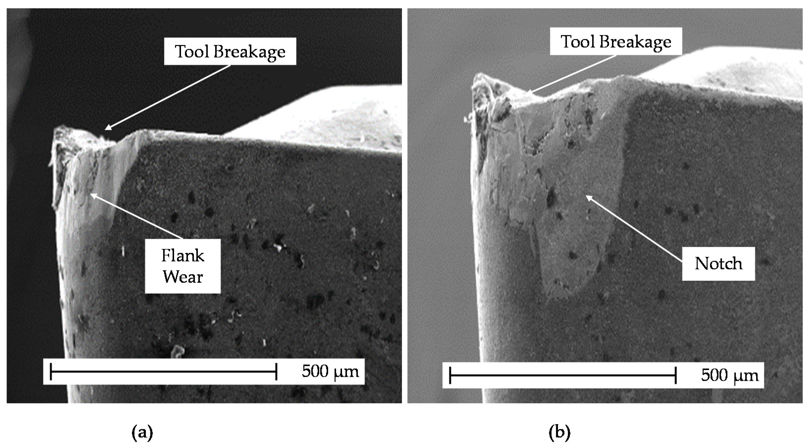
  • The main wear types identified during the turning of Haynes 282 with conventional and high-pressure cooling and Inconel 718 with conventional pressure cooling were flank, chipping, built up edge (BUE), and notch wear. In Inconel 718 turning, flank wear and notch progress at a slower rate than in Haynes 282 turning.
From an industrial point of view, machining processes are feasible for Haynes in different types of conditions and their use is limited mainly due to the higher cost of the material. In addition, it is desirable to start the cutting of Haynes with tools similar to the ones used during the machining of Inconel and gradually adapting the cutting conditions for optimization it. Currently, in the industry, in finishing operations, carbide tools are used due to their better performances compared with other alternatives. However, in most cases, they are used with conventional pressured cutting fluid. With this work, it is shown how by increasing the cutting fluid pressure, the tool life is prolonged.

Author Contributions

Conceptualization: A.D.-Á., J.D.-Á., J.L.C. and M.H.M.; methodology: A.D.-Á., J.D.-Á., and J.L.C.; validation: A.D.-Á., J.D.-Á., and J.L.C.; formal analysis: A.D.-Á., J.D.-Á., J.L.C. and M.H.M.; data curation: A.D.-Á. and J.D.-Á.; writing—original draft: A.D.-Á., J.D.-Á., and J.L.C.; writing—review and editing: A.D.-Á., J.L.C. and M.H.M.; visualization: A.D.-Á. and J.D.-Á.; funding acquisition: A.D.-Á., J.D.-Á., J.L.C. and M.H.M. All authors have read and agreed to the published version of the manuscript.

Funding

The authors gratefully acknowledge the funding support received from the Spanish Ministry of Science and Innovation and the FEDER program for funding the projects PID2020-112628RA-I00, PID2020-118480RB-C22 and PDC2021-121368-C21.

Data Availability Statement

Not applicable.

Conflicts of Interest

The authors declare no conflict of interest.

Abbreviations

CBNCubic boron nitride
fFeed rate
FcCutting force
FfFeed force
FpBack force
FrResultant force
HPJCHigh-pressure cutting fluid
HRUEMHigh-speed rotary ultrasonic elliptical milling
kcSpecific cutting force
kfSpecific feed force
kpSpecific back force
krSpecific resultant force
MQLMinimum quantity lubrication
MQCFMinimum quantity cutting fluids
PCBNPolycrystalline cubic boron nitride
RaArithmetic average roughness
SEMScanning electron microscopy
Smach.tMachined surface per unit time
SedgeMachined surface per cutting edge
TTool life
VcCutting speed

References

  1. Ezugwu, E.O.; Da Silva, R.B.; Bonney, J.; MacHado, Á.R. Evaluation of the performance of CBN tools when turning Ti-6Al-4V alloy with high pressure coolant supplies. Int. J. Mach. Tools Manuf. 2005, 45, 1009–1014. [Google Scholar] [CrossRef]
  2. Thellaputta, G.R.; Chandra, P.S.; Rao, C.S.P. Machinability of Nickel Based Superalloys: A Review. Mater. Today Proc. 2017, 4, 3712–3721. [Google Scholar] [CrossRef]
  3. Zhu, D.; Zhang, X.; Ding, H. Tool wear characteristics in machining of nickel-based superalloys. Int. J. Mach. Tools Manuf. 2013, 64, 60–77. [Google Scholar] [CrossRef]
  4. Gupta, M.K.; Mia, M.; Pruncu, C.I.; Kapłonek, W.; Nadolny, K.; Patra, K.; Mikolajczyk, T.; Pimenov, D.Y.; Sarikaya, M.; Sharma, V.S. Parametric optimization and process capability analysis for machining of nickel-based superalloy. Int. J. Adv. Manuf. Technol. 2019, 102, 3995–4009. [Google Scholar] [CrossRef] [Green Version]
  5. Sarıkaya, M.; Gupta, M.K.; Tomaz, I.; Pimenov, D.Y.; Kuntoğlu, M.; Khanna, N.; Yıldırım, Ç.V.; Krolczyk, G.M. A state-of-the-art review on tool wear and surface integrity characteristics in machining of superalloys. CIRP J. Manuf. Sci. Technol. 2021, 35, 624–658. [Google Scholar] [CrossRef]
  6. Polvorosa, R.; Suárez, A.; de Lacalle, L.N.L.; Cerrillo, I.; Wretland, A.; Veiga, F. Tool wear on nickel alloys with different coolant pressures: Comparison of Alloy 718 and Waspaloy. J. Manuf. Process. 2017, 26, 44–56. [Google Scholar] [CrossRef]
  7. Rodríguez-Millán, M.; Díaz-Álvarez, J.; Bernier, R.; Cantero, J.; Rusinek, A.; Miguelez, M. Thermo-Viscoplastic Behavior of Ni-Based Superalloy Haynes 282 and Its Application to Machining Simulation. Metals 2017, 7, 561. [Google Scholar] [CrossRef] [Green Version]
  8. Kruger, K.L. HAYNES 282 Alloy; Elsevier Ltd.: Amsterdam, The Netherlands, 2016; ISBN 9780081005583. [Google Scholar]
  9. Brittan, A.; Mahaffey, J.; Anderson, M. The performance of Haynes 282 and its weld in supercritical CO2. Mater. Sci. Eng. A 2019, 759, 770–777. [Google Scholar] [CrossRef]
  10. Suárez, A.; Veiga, F.; de Lacalle, L.N.L.; Polvorosa, R.; Wretland, A. An investigation of cutting forces and tool wear in turning of Haynes 282. J. Manuf. Process. 2019, 37, 529–540. [Google Scholar] [CrossRef]
  11. Pimenov, D.Y.; Mia, M.; Gupta, M.K.; Machado, A.R.; Tomaz, Í.V.; Sarikaya, M.; Wojciechowski, S.; Mikolajczyk, T.; Kaplonek, W. Improvement of machinability of Ti and its alloys using cooling-lubrication techniques: A review and future prospect. J. Mater. Res. Technol. 2021, 11, 719–753. [Google Scholar] [CrossRef]
  12. Kurniawan, R.; Park, G.C.; Park, K.M.; Zhen, Y.; Kwak, Y.I.; Kim, M.C.; Lee, J.M.; Ko, T.J.; Park, C.S. Machinability of modified Inconel 713C using a WC TiAlN-coated tool. J. Manuf. Process. 2020, 57, 409–430. [Google Scholar] [CrossRef]
  13. Feito, N.; Muñoz-Sánchez, A.; Díaz-álvarez, A.; Loya, J.A. Analysis of the machinability of carbon fiber composite materials in function of tool wear and cutting parameters using the artificial neural network approach. Materials 2019, 12, 2747. [Google Scholar] [CrossRef] [Green Version]
  14. Ji, H.; Gupta, M.K.; Song, Q.; Cai, W.; Zheng, T.; Zhao, Y.; Liu, Z.; Pimenov, D.Y. Microstructure and machinability evaluation in micro milling of selective laser melted Inconel 718 alloy. J. Mater. Res. Technol. 2021, 14, 348–362. [Google Scholar] [CrossRef]
  15. Ezugwu, E.O.; Bonney, J.; Yamane, Y. An overview of the machinability of aeroengine alloys. J. Mater. Process. Technol. 2003, 134, 233–253. [Google Scholar] [CrossRef]
  16. Grzesik, W.; Niesłony, P.; Habrat, W.; Sieniawski, J.; Laskowski, P. Investigation of tool wear in the turning of Inconel 718 superalloy in terms of process performance and productivity enhancement. Tribol. Int. 2018, 118, 337–346. [Google Scholar] [CrossRef]
  17. Bouzakis, K.D.; Michailidis, N.; Skordaris, G.; Bouzakis, E.; Biermann, D.; M’Saoubi, R. Cutting with coated tools: Coating technologies, characterization methods and performance optimization. CIRP Ann.-Manuf. Technol. 2012, 61, 703–723. [Google Scholar] [CrossRef]
  18. Cantero, J.L.; Díaz-Álvarez, J.; Miguélez, M.H.; Marín, N.C. Analysis of tool wear patterns in finishing turning of Inconel 718. Wear 2013, 297, 885–894. [Google Scholar] [CrossRef] [Green Version]
  19. Tazehkandi, A.H.; Shabgard, M.; Pilehvarian, F. Application of liquid nitrogen and spray mode of biodegradable vegetable cutting fluid with compressed air in order to reduce cutting fluid consumption in turning Inconel 740. J. Clean. Prod. 2015, 108, 90–103. [Google Scholar] [CrossRef]
  20. Gajrani, K.K.; Sankar, M.R.; Dixit, U.S. Environmentally friendly machining with MoS2-filled mechanically microtextured cutting tools. J. Mech. Sci. Technol. 2018, 32, 3797–3805. [Google Scholar] [CrossRef]
  21. Khanna, N.; Agrawal, C.; Pimenov, D.Y.; Singla, A.K.; Machado, A.R.; da Silva, L.R.R.; Gupta, M.K.; Sarikaya, M.; Krolczyk, G.M. Review on design and development of cryogenic machining setups for heat resistant alloys and composites. J. Manuf. Process. 2021, 68, 398–422. [Google Scholar] [CrossRef]
  22. Gupta, M.K.; Song, Q.; Liu, Z.; Sarikaya, M.; Jamil, M.; Mia, M.; Singla, A.K.; Khan, A.M.; Khanna, N.; Pimenov, D.Y. Environment and economic burden of sustainable cooling/lubrication methods in machining of Inconel-800. J. Clean. Prod. 2021, 287, 125074. [Google Scholar] [CrossRef]
  23. Díaz-Álvarez, A.; Díaz-Álvarez, J.; Cantero, J.L.; Miguélez, H. Sustainable high-speed finishing turning of haynes 282 using carbide tools in dry conditions. Metals 2019, 9, 989. [Google Scholar] [CrossRef] [Green Version]
  24. Gajrani, K.K.; Suvin, P.S.; Kailas, S.V.; Sankar, M.R. Hard machining performance of indigenously developed green cutting fluid using flood cooling and minimum quantity cutting fluid. J. Clean. Prod. 2019, 206, 108–123. [Google Scholar] [CrossRef]
  25. Hosseini Tazehkandi, A.; Shabgard, M.; Pilehvarian, F. On the feasibility of a reduction in cutting fluid consumption via spray of biodegradable vegetable oil with compressed air in machining Inconel 706. J. Clean. Prod. 2015, 104, 422–435. [Google Scholar] [CrossRef]
  26. Amiril, S.A.S.; Rahim, E.A.; Syahrullail, S. A review on ionic liquids as sustainable lubricants in manufacturing and engineering: Recent research, performance, and applications. J. Clean. Prod. 2017, 168, 1571–1589. [Google Scholar] [CrossRef] [Green Version]
  27. Wang, C.; Li, K.; Chen, M.; Liu, Z. Evaluation of minimum quantity lubrication effects by cutting force signals in face milling of Inconel 182 overlays. J. Clean. Prod. 2015, 108, 145–157. [Google Scholar] [CrossRef]
  28. Gupta, M.K.; Song, Q.; Liu, Z.; Pruncu, C.I.; Mia, M.; Singh, G.; Lozano, J.A.; Carou, D.; Khan, A.M.; Jamil, M.; et al. Machining characteristics based life cycle assessment in eco-benign turning of pure titanium alloy. J. Clean. Prod. 2020, 251, 119598. [Google Scholar] [CrossRef]
  29. Sarikaya, M.; Güllü, A. Multi-response optimization of minimum quantity lubrication parameters using Taguchi-based grey relational analysis in turning of difficult-to-cut alloy Haynes 25. J. Clean. Prod. 2015, 91, 347–357. [Google Scholar] [CrossRef]
  30. Fang, Z.; Obikawa, T. Influence of cutting fluid flow on tool wear in high-pressure coolant turning using a novel internally cooled insert. J. Manuf. Process. 2020, 56, 1114–1125. [Google Scholar] [CrossRef]
  31. Ezugwu, E.O. High speed machining of aero-engine alloys. J. Braz. Soc. Mech. Sci. Eng. 2004, 26, 1–11. [Google Scholar] [CrossRef] [Green Version]
  32. Zhang, M.; Zhang, D.; Guo, H.; Gao, Z.; Geng, D.; Liu, J.; Jiang, X. High-speed rotary ultrasonic elliptical milling of Ti-6Al-4V using high-pressure coolant. Metals 2020, 10, 500. [Google Scholar] [CrossRef] [Green Version]
  33. Tamil Alagan, N.; Hoier, P.; Zeman, P.; Klement, U.; Beno, T.; Wretland, A. Effects of high-pressure cooling in the flank and rake faces of WC tool on the tool wear mechanism and process conditions in turning of alloy 718. Wear 2019, 434–435, 102922. [Google Scholar] [CrossRef]
  34. Tamil Alagan, N.; Zeman, P.; Mara, V.; Beno, T.; Wretland, A. High-pressure flank cooling and chip morphology in turning Alloy 718. CIRP J. Manuf. Sci. Technol. 2021, 35, 659–674. [Google Scholar] [CrossRef]
  35. Khochtali, H.; Ayed, Y.; Zemzemi, F.; Bensalem, W. Tool wear characteristics in rough turning of Inconel 718 with coated carbide tool under conventional and high-pressure coolant supplies. Int. J. Adv. Manuf. Technol. 2021, 114, 2371–2386. [Google Scholar] [CrossRef]
  36. Díaz-Álvarez, J.; Díaz-Álvarez, A.; Miguélez, H.; Cantero, J. Finishing Turning of Ni Superalloy Haynes 282. Metals 2018, 8, 843. [Google Scholar] [CrossRef] [Green Version]
  37. Otto, R.; Brøtan, V.; Azar, A.S.; Åsebø, O. Processing of Haynes® 282® Alloy by Laser Powder Bed Fusion Technology. In BT—TMS 2019 148th Annual Meeting & Exhibition Supplemental Proceedings; Springer International Publishing: Cham, Switzerland, 2019; pp. 503–510. [Google Scholar]
  38. Díaz-Álvarez, J.; Criado, V.; Miguélez, H.; Cantero, J. PCBN Performance in High Speed Finishing Turning of Inconel 718. Metals 2018, 8, 582. [Google Scholar] [CrossRef] [Green Version]
  39. Pike, L.M. HAYNES® 282TM ALLOY—A new wrought superalloy designed for improved creep strength and fabricability. Processing 2006, 4, 1–9. [Google Scholar]
  40. Karpuschewski, B.; Kundrák, J.; Varga, G.; Deszpoth, I.; Borysenko, D. Determination of specific cutting force components and exponents when applying high feed rates. Procedia CIRP 2018, 77, 30–33. [Google Scholar] [CrossRef]
  41. Díaz-Álvarez, J.; Tapetado, A.; Vázquez, C.; Miguélez, H. Temperature measurement and numerical prediction in machining inconel 718. Sensors 2017, 17, 1531. [Google Scholar] [CrossRef] [PubMed]
Figure 1. Coated carbide tool configuration. Reprinted with permission from ref. [18]. Copyright 2021 Elsevier. Measurements in mm.
Metals 11 01916 g001
Figure 2. Experimental setup.
Metals 11 01916 g002
Figure 3. Initial kc, kf, and kp forces for turning tests on Haynes 282 with high pressure cooling.
Metals 11 01916 g003
Figure 4. Initial specific cutting forces for both Haynes [36] and Inconel [38] under conventional pressure.
Metals 11 01916 g004
Figure 5. Cutting forces progression for Haynes 282 turning tests with high pressure cooling. (a) Vc = 50 m/min and f = 0.1 mm/rev; (b) Vc = 50 m/min and f = 0.15 mm/rev; (c) Vc = 70 m/min and f = 0.1 mm/rev; (d) Vc = 70 m/min and f = 0.15 mm/rev; (e) Vc = 90 m/min and f = 0.1 mm/rev; (f) Vc = 90 m/min and f = 0.15 mm/rev.
Metals 11 01916 g005
Figure 6. Specific cutting forces for both Haynes [36] and Inconel [38] under conventional pressure with worn tool.
Metals 11 01916 g006
Figure 7. SEM images at the end of the tool life for different cutting conditions in Haynes 282 turning tests with high pressure cooling. For 50 m/min and 0.1 mm/rev: (a) relief surface and (b) rake surface view. For 50 m/min and 0.15 mm/rev: (c) relief surface and (d) rake surface view. For 90 m/min and 0.1 mm/rev: (e) relief surface and (f) rake surface view. For 90 m/min and 0.15 mm/rev: (g) relief surface and (h) rake surface view.
Metals 11 01916 g007
Figure 8. SEM images of the tool at the end of the tool life corresponding to Haynes 282 under conventional pressure with cutting speed 50 m/min and feed 0.15 mm/rev: (a) relief surface view, (b) rake surface view [36].
Metals 11 01916 g008
Figure 9. SEM images of the tool at the end of the tool life corresponding to Inconel 718 under conventional pressure with: (a) cutting speed 50 m/min and feed 0.1 mm/rev, (b) cutting speed 70 m/min and feed 0.15 mm/rev [38].
Metals 11 01916 g009
Figure 10. Machined surface roughness for Haynes 282 turning tests with high pressure cooling: (a) 50 m/min; (b) 70 m/min and (c) 90 m/min.
Metals 11 01916 g010
Figure 11. Machined surface roughness for Haynes [36] and Inconel [38] under conventional cooling pressure: (a) feed = 0.1 mm/rev, (b) feed = 0.15 mm/rev.
Metals 11 01916 g011
Table 1. Authors’ contribution in Haynes 282 and Inconel 718 machining.
AuthorMaterialCutting FluidsToolTool Life (min)
Tamil Alagan, N. [33]Inconel 718Conventional/high-pressureUncoated carbide tools-
Tamil Alagan, N. [34]Conventional/high-pressureUncoated carbide tools-
Khochtali, H. [35]Conventional/high-pressureCoated carbide tools-
Díaz-Álvarez, A. [23]Haynes 282DryCoated carbide tools30.1
Díaz-Álvarez, J. [36]Conventional pressureCoated carbide tools33.4
Suárez, A. [10]High-pressure coolantUncoated carbide tools-
Present PaperHigh-pressure coolantCoated carbide tools45.9
Table 2. Element percentages of the Haynes 282 [36].
Element (%)NiCrFeNbMoTiAlCoSiCuMnC
Haynes 2825719.420.87<0.018.522.221.4110.2<0.05<0.010.060.062
Table 3. Conditions for turning tests.
Cutting Speed (m/min)Feed (rev/min)Pass Depth (mm)
500.10.25
0.15
700.1
0.15
90
(Only Haynes 282)
0.1
0.15
Table 4. Tool life for Haynes 282 turning tests with high pressure cooling.
Cutting Speed
(m/min)
Feed
(mm/rev)
Life (min)Machined Surface per Unit Time (mm2/s)Machined Surface per Cutting Edge (mm2)
500.145.983.3229,500
0.1536.8125.0276,000
700.119.2116.7134,400
0.1514.1175.0148,050
900.113.1150.0117,900
0.156.6225.089,100
Table 5. Tool life in terms of cutting time (min) and Sedge (machined surface per edge (mm2)) in the turning of Inconel 718 [38] and Haynes 282 [36] with conventional pressure coolant.
Cutting Speed
(m/min)
Feed
(mm/rev)
Haynes 282Inconel 718
Tool Life (min)Machined Surface Per Cutting Edge (mm2)Tool Life (min)Machined Surface Per Cutting Edge (mm2)
500.133.4167,13943.9219,000
0.1529.2218,91624.9186,000
700.117118,68125.2177,000
0.1514.6153,21514.7155,000
900.1980,961--
0.154.458,826--
Publisher’s Note: MDPI stays neutral with regard to jurisdictional claims in published maps and institutional affiliations.

