


Laser Beam Machining of Tungsten Alloy: Experimental and Numerical Analysis

Faculty of Mechanical Engineering, University of Sarajevo, Vilsonovo Setaliste 9, 71000 Sarajevo, Bosnia and Herzegovina
*
Author to whom correspondence should be addressed.
Metals 2022, 12(11), 1863; https://0-doi-org.brum.beds.ac.uk/10.3390/met12111863
Submission received: 29 September 2022
/
Revised: 26 October 2022
/
Accepted: 28 October 2022
/
Published: 1 November 2022
(This article belongs to the Special Issue Optimization and Analysis of Metal Cutting Processes)
Abstract
:Laser beam machining of various materials has found wide applications in the industry due to its advantages of high-speed machining, no tool wear and no vibration, precision and accuracy, low cost of machining, etc. Investigations into the laser beam machining of uncommon alloy are still limited and more research is needed in this field. In this paper, an analysis of the laser beam machining of tungsten alloy was performed, for cutting and drilling machining processes. First, an experimental analysis of microhardness and microstructure on the laser-cut samples was performed, and then the numerical simulation of the laser beam drilling process and its experimental validation was carried out. The experiments were carried out on a tungsten alloy plate of two different thicknesses, 0.5 and 1 mm. No significant changes in the microhardness, nor in the microstructure characteristics in the heat-affected zone (HAZ), were observed for the cutting conditions considered. A two-dimensional axisymmetric mathematical model for the simulation of the laser beam drilling process is solved by a finite volume method. The model was validated by comparing numerical and experimental results in terms of the size of HAZ and the size and shape of the drilled hole. Experimental and numerical results showed that HAZ is larger in the 0.5-mm-thick plate than in the 1-mm-thick plate under the same drilling conditions. Good agreement was observed between the experimental and numerical results. The developed model improves the understanding of the physical phenomena of laser beam machining and allows the optimization of laser and process parameters.
1. Introduction
Laser beam machining can be applied to a wide range of materials, and this process is a common method in the industry. Laser beam machining offers more advantages over conventional machining processes due to its high-speed machining, the precision of operation, no tool wear and no vibration, accuracy, and low cost of machining [1,2]. During laser beam machining, the laser beam focused on the workpiece surface causes rapid heating of the workpiece material until its melting point. The molten material is then ejected using an assist gas jet of high pressure. Due to the complexity of the laser beam machining process, where a number of different physical phenomena are coupled with each other, modeling and simulation remain a difficult task despite the strong efforts of scientists in the past [3,4]. The finite element method [5,6,7], the artificial neural method [8,9,10], and fuzzy expert systems [11,12] are common methods used in the modelling and simulation of many machining processes, including the laser beam machining process.
The laser beam drilling process has gained a great deal of attention for achieving economic efficiency in the drilling of small holes. An important factor in the modelling and simulation of the laser drilling process is the fact that material is removed via evaporation or/and melting, and the position of the boundary conditions consequently changes with time [13,14]. Ganesh et al. [15] developed a 2D axisymmetric model based on the volume of fluid approach in order to quantitatively analyze the influence of the fluid flow and heat transfer in a laser-drilled hole in turbine airfoil material. Cheng et al. [16] developed a model using the finite difference method in order to predict the size and shape of the hole in the laser drilling of carbon fiber composites. The study indicated that carbon fibers in the heat-affected zone (HAZ) around the drilled hole exhibited swelling up to 50% in diameter. Ho and Lu [17] developed a one-dimensional thermal model in order to predict the erosion of depth in ceramics during the drilling process using a TEM00 (Transverse Electromagnetic Mode) 10 ns pulse Nd-YAG (Neodymium-doped Yttrium Aluminum Garnet) laser. Yan et al. [18] developed a two-dimensional axisymmetric model using the finite element method for the simulation of the temperature field and proceeding with the hole formation during laser percussion drilling of thick-section alumina. The results showed that the temperature and size of the melt front significantly influence the formation of the hole diameter and the deposition of the spatter. Mishra and Yadava [19] developed a prediction model for the laser percussion drilling process of thin aluminum using the coupled methodology of the artificial neural method and the finite element method. The radial point interpolation method was used in [20] for the prediction of the temperature field and penetration depth in metal during the laser drilling process. Digital image correlation was used to measure the small area deformation during the laser drilling process of aluminum alloy [21]. It was confirmed that digital image correlation combined with the laser drilling method can be used with equipment that is simple and low-cost. The Taguchi Grey relation method was used in [22] to analyze the influence of process parameters on surface performance during the laser drilling process of titanium alloy. Results have shown that laser power has a high effect on surface roughness and taper angle. Alsoruji et al. [23] utilized Taguchi Grey relational analysis to optimize the surface roughness and material removal rate as a function of parameters in the laser drilling process of Nickel Inconel 718 alloy. It has been found that surface topography with negligible microcracks on the machined sample can be achieved under optimal process parameters.
Furthermore, numerous research studies have focused on the investigation of the effect of different process parameters on the laser cut surface quality. Chen et al. [24] analyzed the characteristics of microstructure and solidification behavior of the recast layer during CO2 laser cutting of Al2O3 ceramic. Their results showed that the upper and lower parts of the recast layer consist of equiaxed grains, while in the middle part, columnar grains dominate. The effects of the process parameters on the microstructure and kerf size during laser beam cutting of Inconel 738 have been investigated in [25]. It was found that the scanning speed caused different morphologies of the microstructure on the cut surface from the top surface to the base material. The Taguchi method was applied by El Aoud et al. [26] to optimize the surface roughness and analyze the microstructure of the cut edge during the laser cutting of titanium alloy. Voids and microcracks on the laser-cut surface of titanium alloy were observed. The results also showed that by increasing the cutting speed, the number and size of surface microcracks decrease. Li et al. [27] used a high-power fiber laser to cut SiCp/Al composites. They observed different morphologies on machined surfaces including vertical and slant striation, multi-directional striation, dross, and microcracks.
Tungsten alloys are widely used to fabricate shock absorbers, gamma ray shielding material, kinetic energy penetrators, and so on, due to their properties of a high melting point, high density, low thermal coefficient of expansion, high hardness, and good ductility [28,29]. Among tungsten alloys, W-Ni-Fe alloys have found wide application in various industries, such as in the automobile industry, medical applications, the military, the aircraft industry, and the nuclear sector, due to its stability in the absorption of gamma rays and X-rays [29,30,31]. Many studies [32,33,34,35] have been conducted for the application of laser technology such as the laser melting deposition (LMD) process, the selective laser melting (SLM) process, and the laser powder bed fusion (L-PBF) to fabricate tungsten alloys, while laser beam machining (such as laser cutting and laser drilling) of these alloys is still insufficiently researched, especially regarding the microstructure and microhardness of the laser cut parts. This study presents deeper insight into the microstructure and microhardness of the laser-cut material. Laser beam machining of uncommon materials such as tungsten alloys is very interesting and is always a challenging task because the melting temperature of these alloys is too high to be machined by a thermal process.
In this paper, an experimental analysis of the microstructure characteristics and microhardness of laser-cut tungsten alloy is investigated. We outlined the development of a two-dimensional model for temperature-filled predictions during the laser drilling process as well as the prediction of the heat-affected zone size and the shape and size of the drilled hole. The model was solved by a finite volume method and validated by comparing the numerical results with experimental results. The solution domain of moving boundaries due to material melting makes this problem highly nonlinear, and the numerical treatment of this nonlinearity is explained in detail.
2. Materials and Methods
In this section, the mathematical model for the prediction of the temperature field in the workpiece material during laser drilling is described, and the numerical method based on the finite volume method is outlined. The machining conditions and tungsten alloy properties used in experiments and simulations are depicted.
2.1. Mathematical Model
The mathematical model for the prediction of the temperature field in the workpiece material during the laser drilling process is based on the thermal energy balance equation. Together with the appropriate initial and boundary conditions and constitutive equations, it represents a closed system of equations.
The integral form of the equation of thermal energy balance is depicted:
and is valid for an arbitrary part of the volume continuum V bounded by the surface S with normal vector n pointing outwards, where t is time, T is the temperature, ρ is the density of the workpiece material, the specific heat is c, q is a vector of the heat flux, and h is the heat sink that, in the case of the laser drilling process, simulates the latent heat.
The constitutive relation between the heat flux and temperature gradient is given by Fourier’s law:
where k is the thermal conductivity.
In order to complete the mathematical model, initial and boundary conditions have to be specified. At the initial time t = t0, the value of the dependent variable (in this case, the temperature) has to be known at all points of the solution domain:
Boundary conditions have to be defined at all times at all solution domain boundaries. It can be either Dirichlet boundary conditions (temperature):
or Neumann boundary conditions (heat flux):
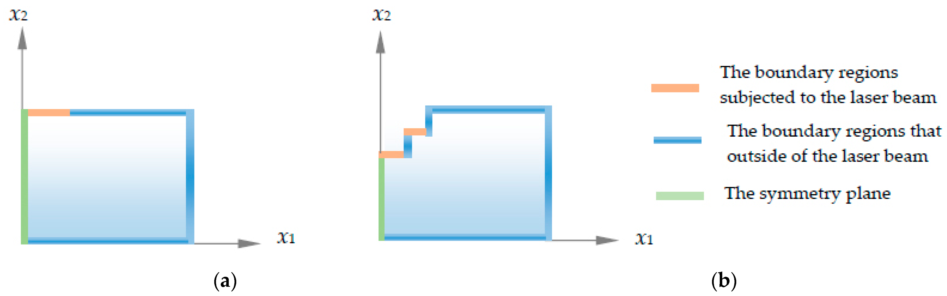
For the Neumann boundary regions, the balance of heat fluxes on the boundary surfaces has to be specified. For the boundary regions subjected to the laser beam, the surface heat fluxes balance equation is given as follows:
where is the heat flux due to convention, is the heat flux due to radiation, and is the heat flux due to heating by the laser beam. For the other boundary regions that are outside the laser beam, the last term on the right side of Equation (6) is omitted.
2.2. Numerical Method
The Equation governing the energy balance (1) is discretized using the finite volume method (FVM) that is described in detail in [14]. As with all numerical methods, it consists of time, space, and equation, discretization. Due to the removal of material from the machining zone, the position of the solution domain boundaries changes over time as shown in Figure 1, making the problem highly nonlinear.
If the heat sink in a certain cell is equal to the latent heat, and if the temperature of this cell is equal to the liquid temperature, then this cell is removed from the finite volume mesh because this cell is melted and ejected using an assist gas jet. So, the new domain boundaries are set and the boundary conditions are changed based on these domain boundaries.
In the boundary regions that are subjected to the laser beam during the drilling process, the boundary conditions are defined by Equation (6), or:
where is the coefficient of heat transfer by convection, is the ambient temperature, T is the boundary temperature, σ is the Stefan–Boltzmann constant, ε is the coefficient of radiation emission, α is the coefficient of absorption, and is the laser intensity.
In this study, for a uniform Gaussian distribution of laser intensity, a two-dimensional model is considered. The laser intensity is given by:
where P(t) is the laser power, r is the radial coordinate, and rf is the radius of the focus point. For numerical simulation, the laser power was considered a time-dependent parameter, and it is defined as follows:
where K is the laser beam quality factor, is the default laser power, is the actual laser power, and is the required time to achieve the actual laser power. In this study, for numerical calculation, the actual measured laser power was taken as input data.
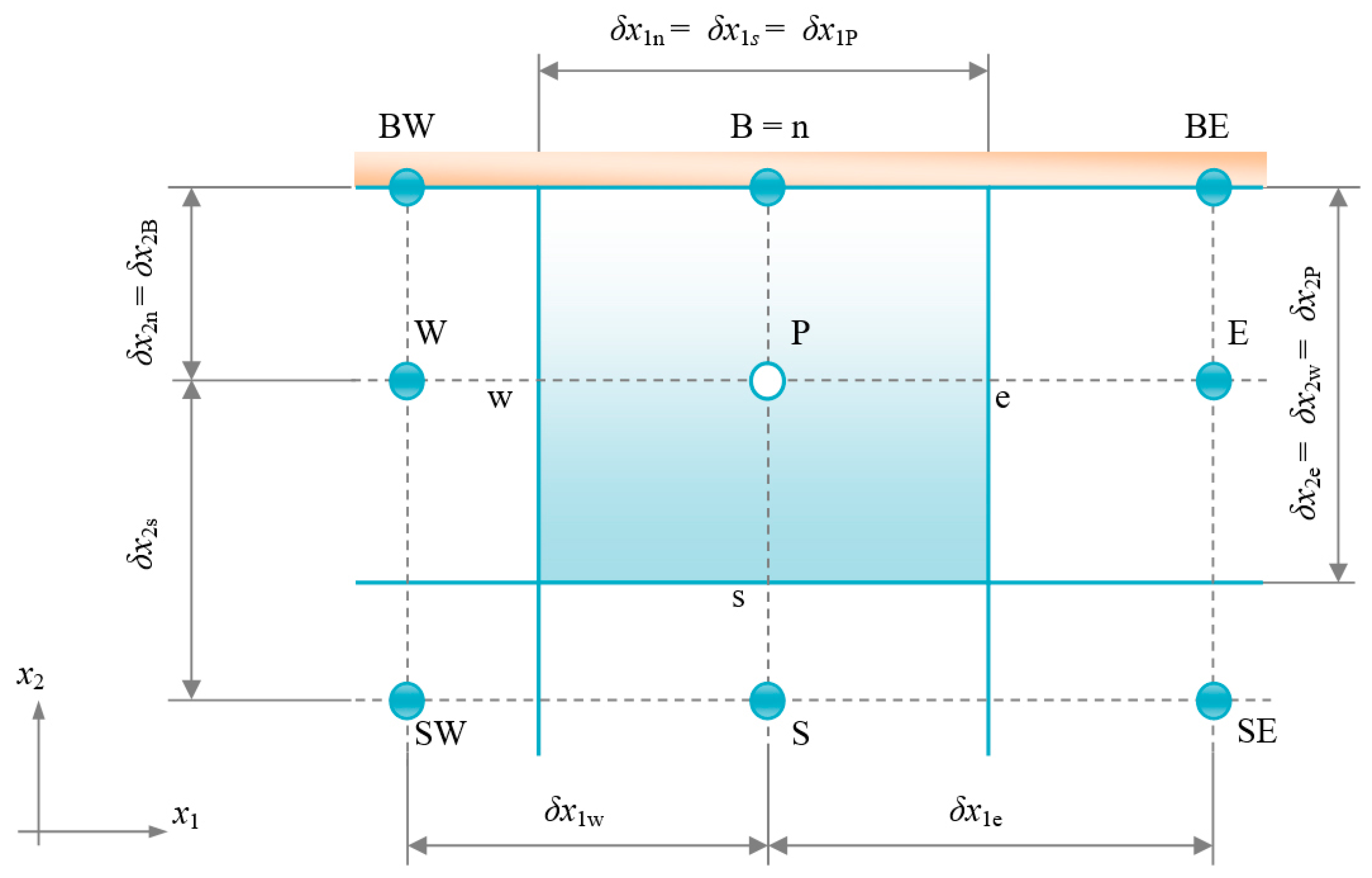
In order to calculate the boundary temperature on the face coinciding with the solution domain boundary, it was assumed that the north cell face is the boundary region that is subjected to the laser beam, as shown in Figure 2.
After introducing constitutive relation (2) into Equation (1), the discretized form of this equation for the 2D control volume shown in Figure 2 can be written as follows:
where superscript m and (m − 1) denote the value at two successive instants of time, is the time step, and subscript P refers to the cell P. Integrals in the thermal energy balance equation are calculated by employing the Mid-Point rule, and the linear spatial variation of dependent variables is assumed, resulting in second-order accurate spatial discretization. For temporal variation, a two-time-level linear variation of temperature with time assumed, and physical properties and variables on the right side of Equation (10) are evaluated at the time instant m, i.e., a fully implicit time differencing scheme was employed. TE, TW, and TS are temperature values at the center of the neighboring cells to cell P, and TB is the boundary temperature.
The boundary temperature in Equation (10) is unknown, and it can be obtained from the discretized surface heat fluxes balance Equation (7):
Equation (11) is linearized in the manner that the non-linear term in this equation is taken as a known value from the previous iteration during the iterative process of solving the linearized system of equations. From Equation (11), the temperature can be expressed as:
where
and the superscript (n − 1) denotes the value in the previous iteration.
Substituting Equation (12) into Equation (10), the discretized thermal energy equation for a 2D model for each control volume (CV) can be written in the following form:
where summation is to be performed over all three cells of neighboring cell P, and coefficients and , and term b have the following form:
where all variables in Equations (15)–(17) refer to the current time instant, unless indicated otherwise.
In the boundary regions that are outside the influence of the laser beam, the boundary conditions are defined as follows:
In this case, Equations (12) and (17) do not contain the last term on the right side.
2.3. Experimental Setup
The experiments were conducted using a CO2 Laser System, with a nominal laser power of 2000 W. The material of the machined workpiece used in the experiments was tungsten alloy (93 wt% W with the rest comprised of Ni and Fe) plates with two different thicknesses, 0.5 mm and 1 mm. Nitrogen was used as an assist gas in the laser drilling process. Oxygen, nitrogen, and air were used as assist gases during the laser cutting process, because these are the most commonly used gases in laser metal cutting. The process parameters and thermo-physical properties of tungsten alloy are given in Table 1 and Table 2, respectively.
In Table 1, is the drilled time, and in Table 2, is the liquid temperature and latent heat. The initial temperature of the workpiece material was the same as the ambient temperature. The thermal conductivity k and the radiation emission coefficient were considered temperature-dependent parameters. These parameters are defined in [36]. The temperature-dependent specific heat c used in the simulation is given in Table 3.
The Vickers hardness tester was used for microhardness measurements, and an optical microscope was used to capture images of the microstructure.
3. Results and Discussion
In this section, experimental and numerical results are presented for laser beam machining of tungsten alloy. The microhardness and microstructure of the laser-cut samples, the size of the heat-affected zone, and the shape and size of the drilled hole are shown.
3.1. Microhardness of the Cut Sample
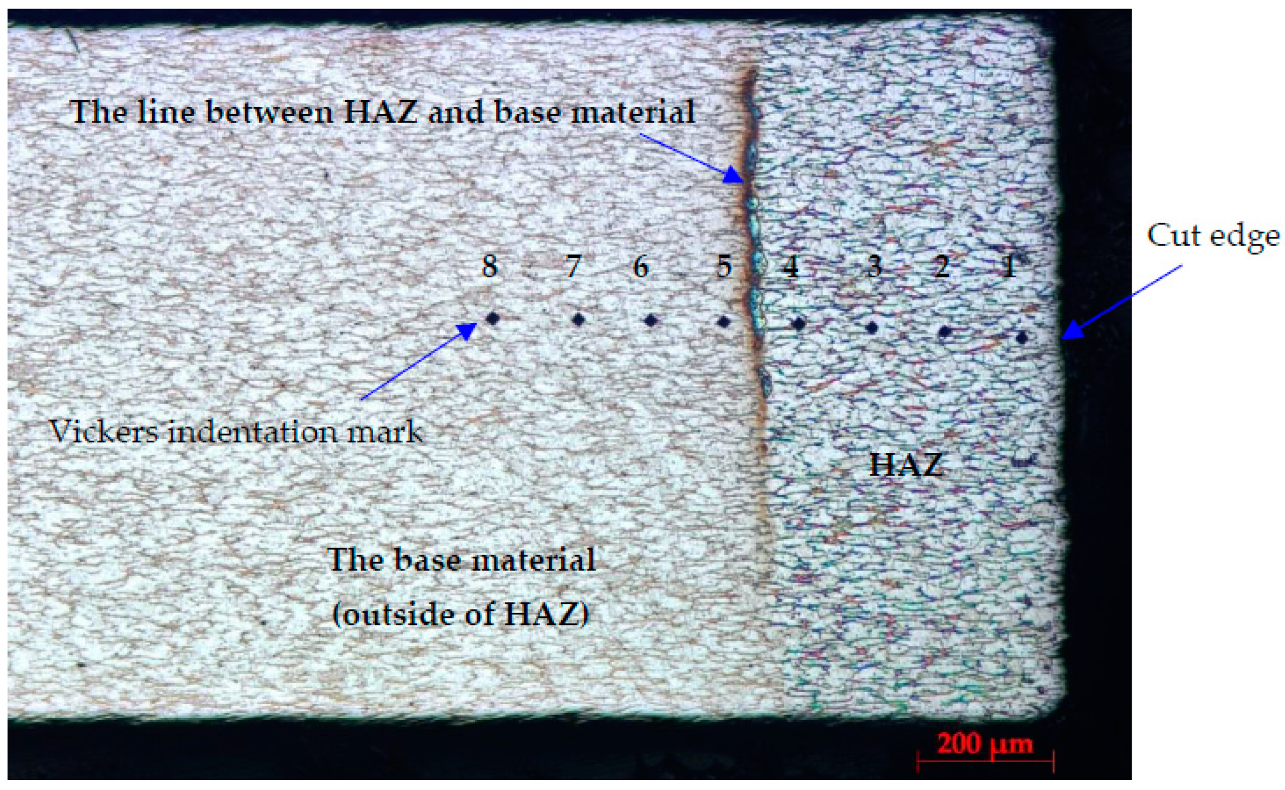
Microhardness measurements according to ISO 6507 were performed in the heat-affected zone and in the base material outside the heat-affected zone. Vickers microhardness was measured in eight different points, as shown in Figure 3. The distance between the microhardness indentations was 150 μm. The first microhardness indentation was taken at a distance of 50 μm from the cut edge.
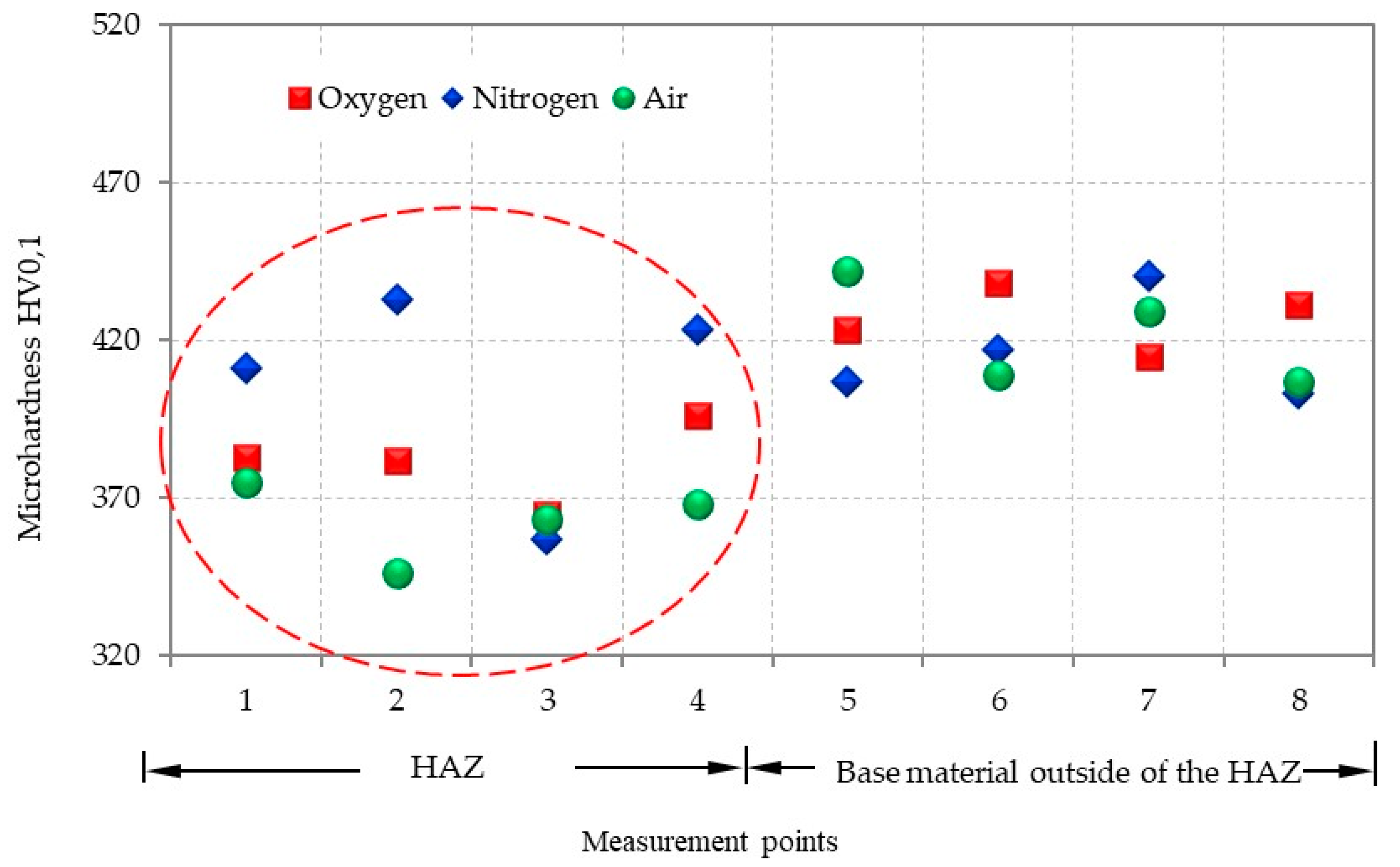
Dissipation of the hardness values in the HAZ and in the base material outside the HAZ for all of three assist gases used during laser cutting of tungsten alloy is shown in Figure 4. It can be observed that the hardness values are more dissipated in the heat-affected zone than in the base material for all three assist gases used. However, in general, it can be concluded that no significant changes in the microhardness were observed for all three assist gases used.
3.2. Microstructure of the Cut Sample
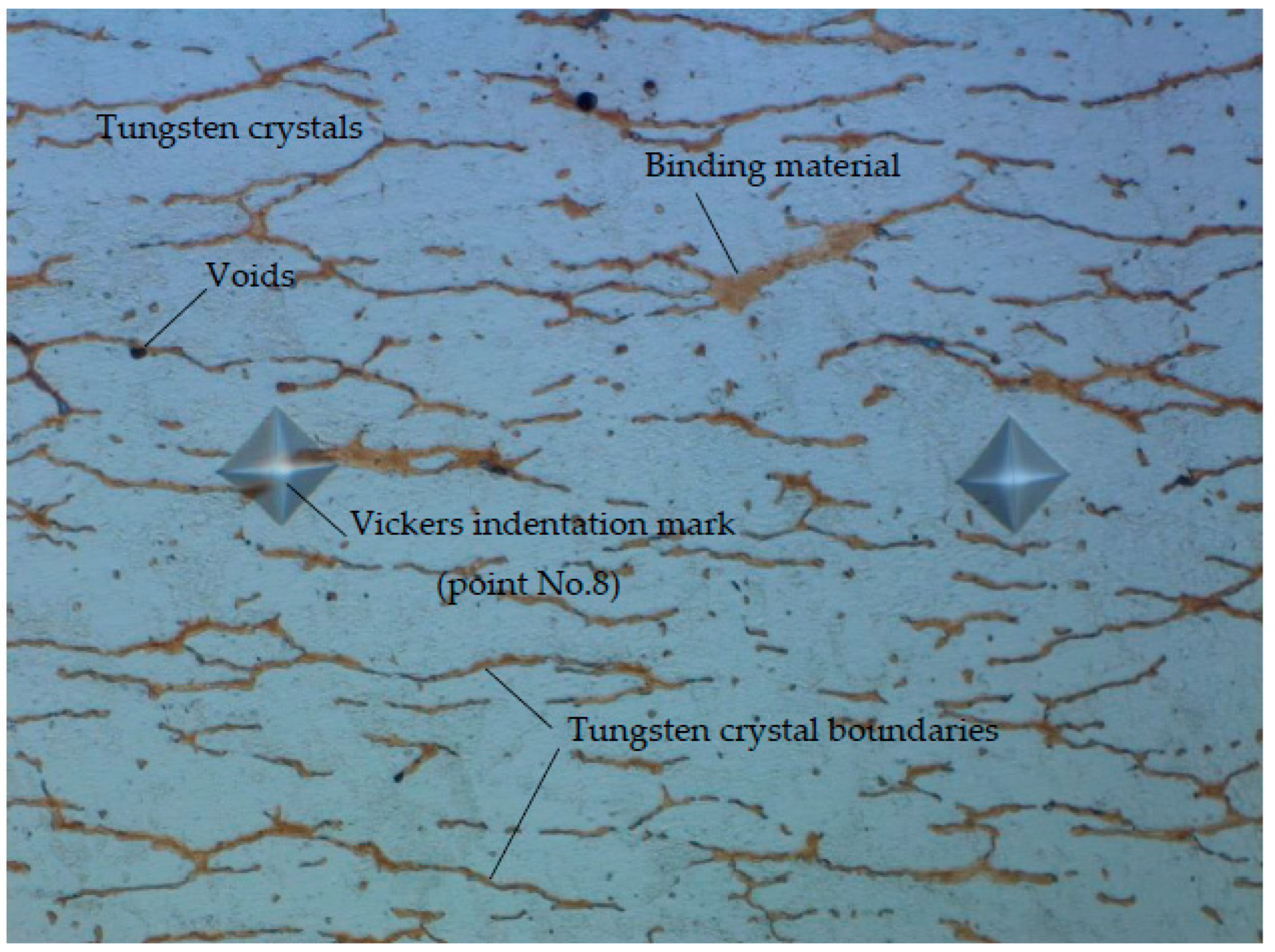
In order to determine eventual changes in the microstructure during laser cutting of tungsten alloy, the microstructure in the base material (Figure 5) was compared with the microstructure in the heat-affected zone (Figure 6).
Based on the microstructure shown in Figure 5, the following can be stated:
- The basic constituent of the microstructure is tungsten crystals.
- Tungsten crystal boundaries are clearly visible.
- The binding material is located at the crystal boundaries.
- In some places, the voids are observed at the crystal boundaries.
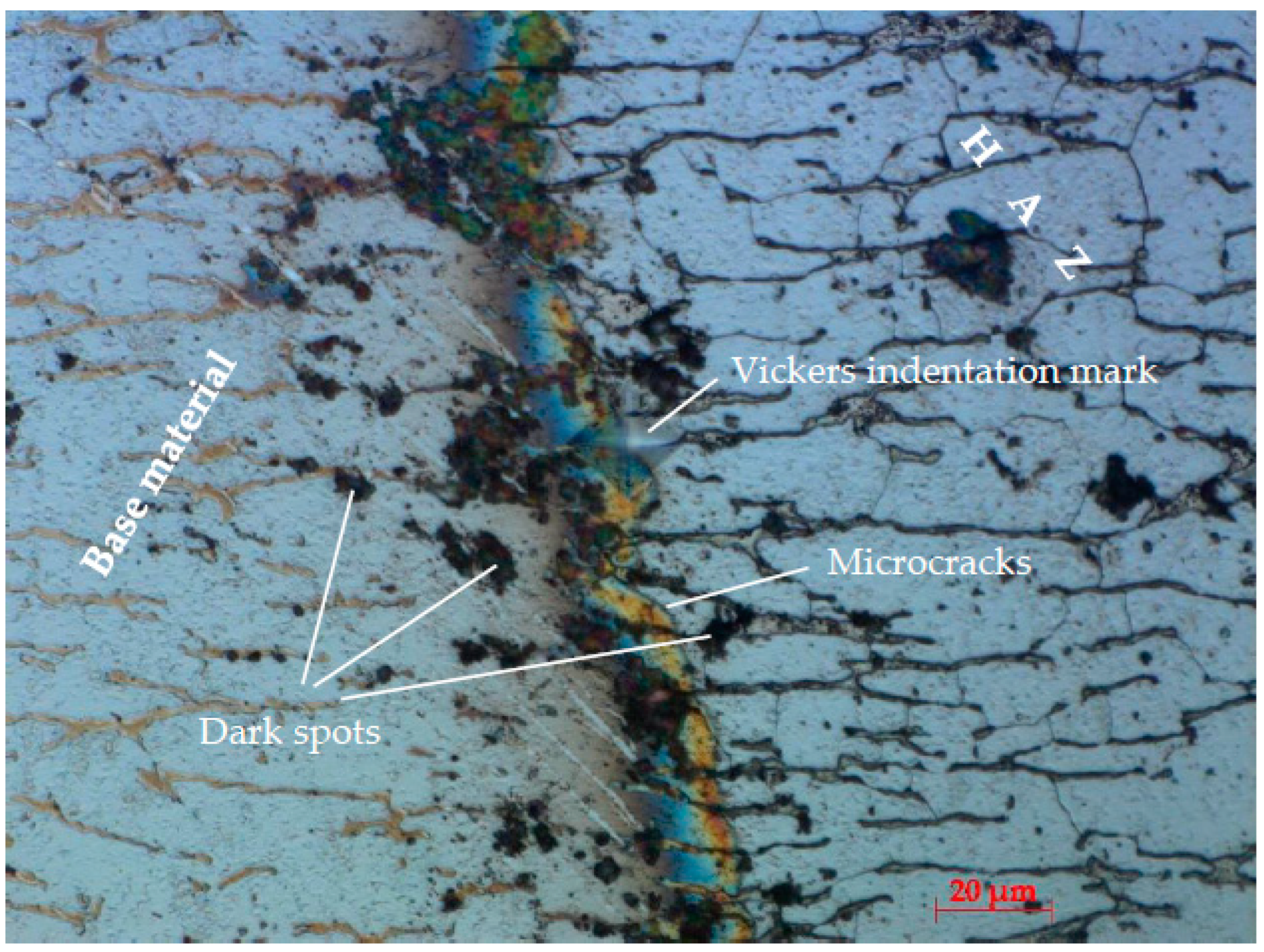
Based on the microstructure shown in Figure 6, the following can be stated:
- The orientation of the tungsten crystals has not been changed.
- No changes in the crystal size.
- Microcracks are located at the very border of the heat-affected zone. Microcracks are trans-crystalline.
3.3. Numerical Results and Experimental Validation
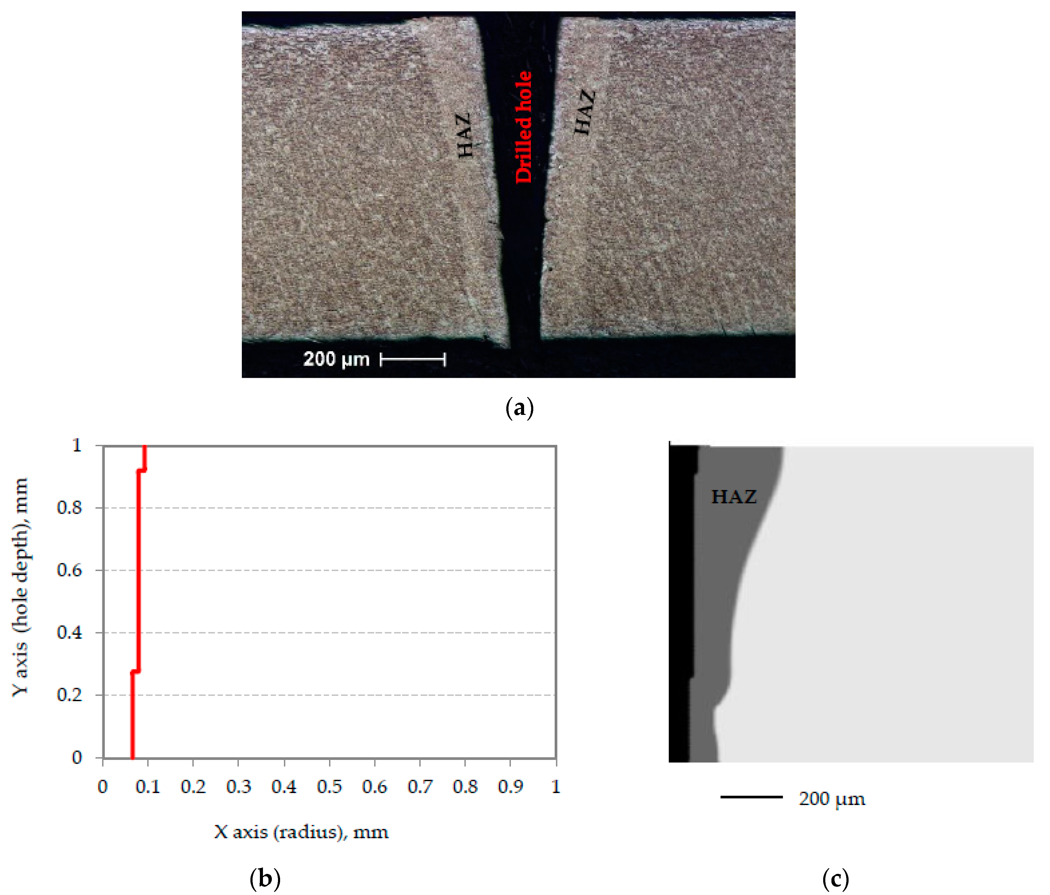
In this section, experimental and numerical results were compared in terms of the size of the heat-affected zone and the size and shape of the hole during the laser drilling process of tungsten alloy, 0.5 mm and 1 mm in thickness. The experimental results and numerical results for a 1-mm-thick tungsten alloy plate are shown in Figure 7. The total drilling time was 8 ms.
Experimental results (Figure 7a) show that the size of the heat-affected zone is non-uniformly distributed along the cross-section of the sample. The size of the HAZ is larger at the entrance side of the laser beam into the workpiece. Furthermore, a variation in the hole diameter along the depth of the hole was observed. Thus, a conical-shaped hole was obtained. The hole diameter on the entrance side of the laser beam into the workpiece is approximately 60% larger than the hole diameter on the exit side of the laser beam. Results show good agreement between experimental (Figure 7a) and numerical (Figure 7b,c) results for the size of the HAZ and the shape and size of the drilled hole achieved.
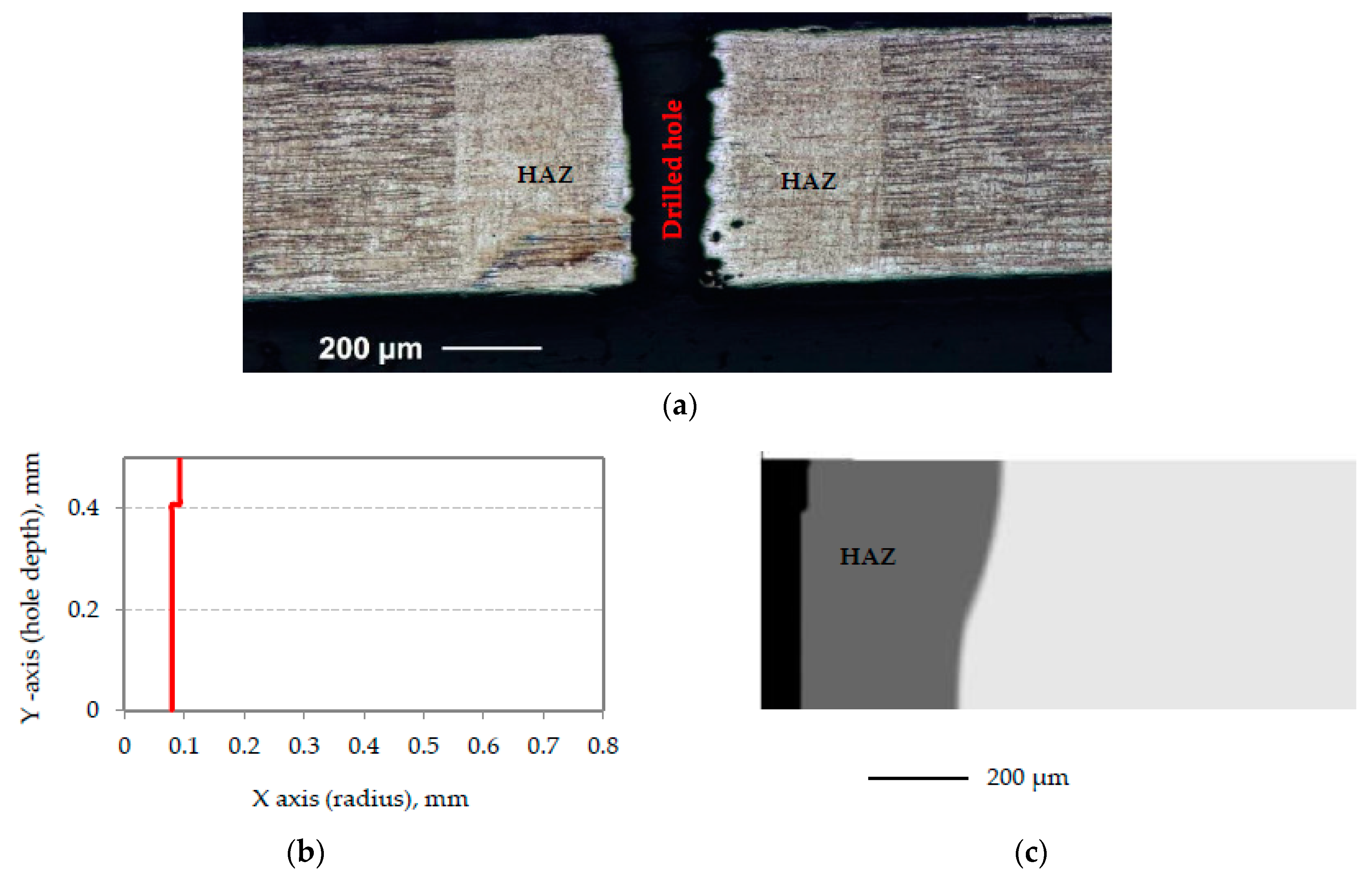
Figure 8 presents the experimental and numerical results for a 0.5-mm-thick tungsten alloy plate. Furthermore, the total drilling time was 8 ms.
The experimental results, depicted in Figure 8a, show that the size of the heat-affected zone is less non-uniformly distributed along the sample cross-section than in the case of a sample thickness of 1 mm (Figure 7a). A variation in the hole diameter along the hole depth was also observed, but this variation was significantly less than in the sample with a thickness of 1 mm. In this case, the hole diameter at the entrance side of the laser beam into the workpiece is approximately 32% larger than the hole diameter at the exit side of the laser beam. Moreover, good agreement between the experimental and numerical results for the HAZ size and the shape and size of the drilled hole was achieved.
For the same drilling conditions, experimental and numerical results showed that the HAZ was larger in the 0.5-mm-thick plate than in the 1-mm-thick plate. Thus, due to the input of the same amount of heat into the plates, it resulted in a larger heat-affected zone when laser drilling the thinner plate. Furthermore, a variation of the hole diameter along the hole depth was observed for both plate thicknesses, but this variation was significantly less in the thinner plate.
Based on the obtained results, it can be concluded that the accuracy of the calculation is such that the numerical results can be used in the optimization of the laser drilling process.
4. Conclusions
In the present study, an experimental investigation into the microhardness and microstructure of the laser cut of tungsten alloy was successfully conducted. In addition, an experimental investigation and mathematical modelling of the heat-affected zone and the shape of the hole during the laser drilling process of a 0.5 mm and 1 mm thick tungsten alloy were successfully performed.
Based on the experimental results, it can be concluded that there were no significant changes in the hardness values in the heat-affected zone during the laser cutting of tungsten alloy. Furthermore, no changes were observed in the characteristics of the microstructure in the heat-affected zone. In some laser-cut samples, there was the appearance of microcracks at the very border of the heat-affected zone. In any case, it is necessary to carry out other methods of microstructure analysis to detect microcracks.
A very nonlinear mathematical issue due to the highly nonlinear equations of the mathematical model, the presence of latent heat, and the constant change in the spatial domain as a result of the hole formation was solved y using the finite volume method. A highly nonlinear discretized governing equation was efficiently solved by an iterative solver using the conjugate gradient method for each iteration to solve the linearized discretized equations.
The presented numerical method gives very good results in the prediction of the heat-affected zone and the shape of the hole during the laser drilling process, which indicates that the numerical results can be used for practical purposes to optimize the laser drilling process of any materials.
In future work, more detailed discussions on the effect of different process parameters such as the laser energy per pulse, the drilling time, and the type of material will be considered, as well as numerical simulation of the laser cutting process.
Author Contributions
Conceptualization, D.B.-H. and I.B.; data curation, I.B.; formal analysis, D.B.-H.; funding acquisition, D.B.-H. and I.B.; investigation, D.B.-H. and I.B.; methodology, D.B.-H. and I.B.; resources, D.B.-H. and I.B.; software, D.B.-H.; supervision, I.B.; validation, I.B.; visualization, D.B.-H. and I.B.; writing—original draft, D.B.-H.; writing—review and editing, D.B.-H. and I.B. All authors have read and agreed to the published version of the manuscript.
Funding
This research was funded by Federal Ministry of Education and Science, B&H.
Institutional Review Board Statement
Not applicable.
Informed Consent Statement
Not applicable.
Data Availability Statement
The data that support the findings of this study are available from the corresponding author.
Conflicts of Interest
The authors declare no conflict of interest.
References
- Yilbas, B.S. 1.12 Laser Machining Processes. In Comprehensive Materials Finishing; Elsevier: Amsterdam, The Netherlands, 2017; pp. 344–363. ISBN 978-0-12-803249-7. [Google Scholar]
- Girdu, C.C.; Gheorghe, C. Energy Efficiency in CO2 Laser Processing of Hardox 400 Material. Materials 2022, 15, 4505. [Google Scholar] [CrossRef] [PubMed]
- Dubey, A.K.; Yadava, V. Laser Beam Machining—A Review. Int. J. Mach. Tools Manuf. 2008, 48, 609–628. [Google Scholar] [CrossRef]
- Bakhtiyari, A.N.; Wang, Z.; Wang, L.; Zheng, H. A Review on Applications of Artificial Intelligence in Modeling and Optimization of Laser Beam Machining. Opt. Laser Technol. 2021, 135, 106721. [Google Scholar] [CrossRef]
- Kadri, M.B.; Nisar, S.; Khan, S.Z.; Khan, W.A. Comparison of ANN and Finite Element Model for the Prediction of Thermal Stresses in Diode Laser Cutting of Float Glass. Opt. Int. J. Light Electron Opt. 2015, 126, 1959–1964. [Google Scholar] [CrossRef]
- Moradi, M.; Moghadam, M.K.; Shamsborhan, M.; Beiranvand, Z.M.; Rasouli, A.; Vahdati, M.; Bakhtiari, A.; Bodaghi, M. Simulation, Statistical Modeling, and Optimization of CO2 Laser Cutting Process of Polycarbonate Sheets. Optik 2021, 225, 164932. [Google Scholar] [CrossRef]
- Xiao, H.; Zhang, W.; Zhou, Y.; Liu, M.; Zhou, G. A Numerical Simulation and Experimental Study on the Ultrafast Double-Laser Precision Cutting of Sapphire Materials. Crystals 2022, 12, 867. [Google Scholar] [CrossRef]
- Klancnik, S.; Begic-Hajdarevic, D.; Paulic, M.; Ficko, M.; Cekic, A.; Cohodar Husic, M. Prediction of Laser Cut Quality for Tungsten Alloy Using the Neural Network Method. Stroj. Vestn. J. Mech. Eng. 2015, 61, 714–720. [Google Scholar] [CrossRef]
- Yongbin, Y.; Bagherzadeh, S.A.; Azimy, H.; Akbari, M.; Karimipour, A. Comparison of the Artificial Neural Network Model Prediction and the Experimental Results for Cutting Region Temperature and Surface Roughness in Laser Cutting of AL6061T6 Alloy. Infrared Phys. Technol. 2020, 108, 103364. [Google Scholar] [CrossRef]
- Norkey, G.; Pratap Singh, K.; Prajapati, A.; Sharma, V. Intelligent Parameters Optimization for Laser Cutting of Highly Reflective and Thermally Conductive Materials Using Artificial Neural Network. Mater. Today Proc. 2021, 46, 4757–4764. [Google Scholar] [CrossRef]
- Syn, C.Z.; Mokhtar, M.; Feng, C.J.; Manurung, Y.H.P. Approach to Prediction of Laser Cutting Quality by Employing Fuzzy Expert System. Expert Syst. Appl. 2011, 38, 7558–7568. [Google Scholar] [CrossRef]
- Hossain, A.; Hossain, A.; Nukman, Y.; Hassan, M.A.; Harizam, M.Z.; Sifullah, A.M.; Parandoush, P. A Fuzzy Logic-Based Prediction Model for Kerf Width in Laser Beam Machining. Mater. Manuf. Process. 2016, 31, 679–684. [Google Scholar] [CrossRef]
- Parandoush, P.; Hossain, A. A Review of Modeling and Simulation of Laser Beam Machining. Int. J. Mach. Tools Manuf. 2014, 85, 135–145. [Google Scholar] [CrossRef]
- Begic-Hajdarevic, D.; Bijelonja, I. Experimental and Numerical Investigation of Temperature Distribution and Hole Geometry during Laser Drilling Process. Procedia Eng. 2015, 100, 384–393. [Google Scholar] [CrossRef] [Green Version]
- Ganesh, R.K.; Bowley, W.W.; Bellantone, R.R.; Hahn, Y. A Model for Laser Hole Drilling in Metals. J. Comput. Phys. 1996, 125, 161–176. [Google Scholar] [CrossRef]
- Cheng, C.F.; Tsui, Y.C.; Clyne, T.W. Application of a Three-Dimensional Heat Flow Model to Treat Laser Drilling of Carbon Fibre Composites. Acta Mater. 1998, 46, 4273–4285. [Google Scholar] [CrossRef]
- Ho, C.Y.; Lu, J.K. A Closed Form Solution for Laser Drilling of Silicon Nitride and Alumina Ceramics. J. Mater. Process. Technol. 2003, 140, 260–263. [Google Scholar] [CrossRef]
- Yan, Y.; Ji, L.; Bao, Y.; Jiang, Y. An Experimental and Numerical Study on Laser Percussion Drilling of Thick-Section Alumina. J. Mater. Process. Technol. 2012, 212, 1257–1270. [Google Scholar] [CrossRef]
- Mishra, S.; Yadava, V. Modeling and Optimization of Laser Beam Percussion Drilling of Thin Aluminum Sheet. Opt. Laser Technol. 2013, 48, 461–474. [Google Scholar] [CrossRef]
- Abidou, D.; Yusoff, N.; Nazri, N.; Omar Awang, M.A.; Hassan, M.A.; Sarhan, A.A.D. Numerical Simulation of Metal Removal in Laser Drilling Using Radial Point Interpolation Method. Eng. Anal. Bound. Elem. 2017, 77, 89–96. [Google Scholar] [CrossRef]
- Ho, C.-C.; Li, G.-H. Study on the Measurement of Laser Drilling Depth by Combining Digital Image Relationship Measurement in Aluminum. Materials 2021, 14, 489. [Google Scholar] [CrossRef]
- Muthuramalingam, T.; Akash, R.; Krishnan, S.; Phan, N.H.; Pi, V.N.; Elsheikh, A.H. Surface Quality Measures Analysis and Optimization on Machining Titanium Alloy Using CO2 Based Laser Beam Drilling Process. J. Manuf. Process. 2021, 62, 1–6. [Google Scholar] [CrossRef]
- Alsoruji, G.; Muthuramalingam, T.; Moustafa, E.B.; Elsheikh, A. Investigation and TGRA Based Optimization of Laser Beam Drilling Process during Machining of Nickel Inconel 718 Alloy. J. Mater. Res. Technol. 2022, 18, 720–730. [Google Scholar] [CrossRef]
- Chen, X.; Ji, L.; Bao, Y.; Jiang, Y. Improving Cutting Quality by Analysis of Microstructure Characteristics and Solidification Behaviour of Recast Layer Formation on Laser Cut Ceramic. J. Eur. Ceram. Soc. 2012, 32, 2203–2211. [Google Scholar] [CrossRef]
- Wei, J.; Ye, Y.; Sun, Z.; Liu, L.; Zou, G. Control of the Kerf Size and Microstructure in Inconel 738 Superalloy by Femtosecond Laser Beam Cutting. Appl. Surf. Sci. 2016, 370, 364–372. [Google Scholar] [CrossRef]
- El Aoud, B.; Boujelbene, M.; Boudjemline, A.; Bayraktar, E.; Ben Salem, S.; Elbadawi, I. Investigation of Cut Edge Microstructure and Surface Roughness Obtained by Laser Cutting of Titanium Alloy Ti-6Al-4V. Mater. Today Proc. 2021, 44, 2775–2780. [Google Scholar] [CrossRef]
- Li, M.; Han, H.; Jiang, X.; Zhang, X.; Chen, Y. Surface Morphology and Defect Characterization during High-Power Fiber Laser Cutting of SiC Particles Reinforced Aluminum Metal Matrix Composite. Opt. Laser Technol. 2022, 155, 108419. [Google Scholar] [CrossRef]
- Hafizoglu, H.; Durlu, N.; Konokman, H.E. Effects of Sintering Temperature and Ni/Fe Ratio on Ballistic Performance of Tungsten Heavy Alloy Fragments. Int. J. Refract. Met. Hard Mater. 2019, 81, 155–166. [Google Scholar] [CrossRef]
- Liu, W.; Sheng, Q.; Ma, Y.; Cai, Q.; Wang, J.; Liu, Y. Interfacial Microstructures, Residual Stress and Mechanical Analysis of Hot Isostatic Pressing Diffusion Bonded Joint of 93W–4.9Ni–2.1Fe Alloy and 30CrMnSiNi2A Steel. Fusion Eng. Des. 2020, 156, 111602. [Google Scholar] [CrossRef]
- Xie, Y.-F.; Zhou, L.-L.; Zhang, X.-Y.; Li, X.-X.; Zhou, Z.-L.; Zhang, X.-H. Microstructure and Properties of W–4.9Ni–2.1Fe Heavy Alloy with Dy2O3 Addition. Rare Met. 2019, 38, 746–753. [Google Scholar] [CrossRef]
- Ageev, E.V.; Pereverzev, A.S.; Selyutin, V.L. Study of the Particle Size Distribution of Electroerosive Materials Obtained from Waste Alloys Based on W-Ni-Fe in Lighting Kerosene. IOP Conf. Ser. Mater. Sci. Eng. 2020, 971, 032009. [Google Scholar] [CrossRef]
- Iveković, A.; Omidvari, N.; Vrancken, B.; Lietaert, K.; Thijs, L.; Vanmeensel, K.; Vleugels, J.; Kruth, J.-P. Selective Laser Melting of Tungsten and Tungsten Alloys. Int. J. Refract. Met. Hard Mater. 2018, 72, 27–32. [Google Scholar] [CrossRef]
- Iveković, A.; Montero-Sistiaga, M.L.; Vanmeensel, K.; Kruth, J.-P.; Vleugels, J. Effect of Processing Parameters on Microstructure and Properties of Tungsten Heavy Alloys Fabricated by SLM. Int. J. Refract. Met. Hard Mater. 2019, 82, 23–30. [Google Scholar] [CrossRef]
- Li, C.; Wang, Y.; Ma, S.; Yang, X.; Li, J.; Zhou, Y.; Liu, X.; Tang, J.; Wang, X.; Le, G. Densification, Microstructural Evolutions of 90W-7Ni-3Fe Tungsten Heavy Alloys during Laser Melting Deposition Process. Int. J. Refract. Met. Hard Mater. 2020, 91, 105254. [Google Scholar] [CrossRef]
- Schwanekamp, T.; Müller, A.; Reuber, M.; Gobran, H.; Gdoura, N.; von Cetto, S. Investigations on Laser Powder Bed Fusion of Tungsten Heavy Alloys. Int. J. Refract. Met. Hard Mater. 2022, 109, 105959. [Google Scholar] [CrossRef]
- Lassner, E.; Schubert, W.-D. Tungsten: Properties, Chemistry, Technology of the Element, Alloys, and Chemical Compounds; Kluwer Academic/Plenum Publishers: New York, NY, USA, 1999; ISBN 978-0-306-45053-2. [Google Scholar]
Figure 1.
The solution domain: (a) The initial solution domain; (b) the solution domain during laser drilling process.
Figure 1.
The solution domain: (a) The initial solution domain; (b) the solution domain during laser drilling process.

Figure 2.
2D control volume with scheme of labelling.

Figure 3.
Indentation points for measuring microhardness (cross-section).

Figure 4.
Microhardness values dissipation in the HAZ and the base material in laser cutting of tungsten alloy.
Figure 4.
Microhardness values dissipation in the HAZ and the base material in laser cutting of tungsten alloy.

Figure 5.
Microscope image of microstructure (cross-section) in the base material outside the HAZ.

Figure 6.
Microscope image of microstructure (cross-section) in the line between the base material and the heat-affected zone (air as assist gas).
Figure 6.
Microscope image of microstructure (cross-section) in the line between the base material and the heat-affected zone (air as assist gas).

Figure 7.
Heat-affected zone (HAZ) and the shape of the drilled hole for a 1-mm-thick tungsten alloy plate: (a) Experiment; (b) FVM—shape of the hole; (c) FVM—heat-affected zone [14].
Figure 7.
Heat-affected zone (HAZ) and the shape of the drilled hole for a 1-mm-thick tungsten alloy plate: (a) Experiment; (b) FVM—shape of the hole; (c) FVM—heat-affected zone [14].

Figure 8.
Heat-affected zone (HAZ) and the shape of the drilled hole for a 0.5-mm-thick tungsten alloy plate: (a) Experiment; (b) FVM—shape of the hole; (c) FVM—heat-affected zone.
Figure 8.
Heat-affected zone (HAZ) and the shape of the drilled hole for a 0.5-mm-thick tungsten alloy plate: (a) Experiment; (b) FVM—shape of the hole; (c) FVM—heat-affected zone.


Table 1.
Laser drilling conditions used in the experiment and simulation.
| Parameter | Symbol | Values |
|---|---|---|
| Default laser power | Pa | 1000 W |
| Actual laser power | KPa | 974 W |
| The required time to achieve the actual laser power | tt | 5 × 10⁻³ s |
| The drilled time | td | 8 × 10⁻³ s |
| Radius of the focus point | rf | 0.105 mm |
| Nitrogen assist gas pressure | p | 6 bars |
Table 2.
Properties of tungsten alloy used in the simulation.
| Parameter | Symbol | Values |
|---|---|---|
| The liquidus temperature | TL | 3100 °C |
| The ambient temperature | 20 °C | |
| The latent heat | HL | 250 kJ kg−1 |
| The coefficient of absorption | α | 0.86 |
| Material density | ρ | 17,600 kg m−3 |
| Stefan-Boltzmann constant | σ | 5.67 × 10⁻⁸ W m−2 K−4 |
| The coefficient of heat transfer by convection | λ | 25 W m−2 K−1 |
Table 3.
The specific heat used in the simulation.
| T, (°C) | 100 | 200 | 300 | 400 | 500 | 600 | 700 | 800 | 900 | 1000 | 1100 | >1100 |
|---|---|---|---|---|---|---|---|---|---|---|---|---|
| c, (J kg−1 K−1) | 163 | 168 | 166 | 166 | 166 | 165 | 167 | 167 | 167 | 175 | 180 | 180 |
Publisher’s Note: MDPI stays neutral with regard to jurisdictional claims in published maps and institutional affiliations. |
© 2022 by the authors. Licensee MDPI, Basel, Switzerland. This article is an open access article distributed under the terms and conditions of the Creative Commons Attribution (CC BY) license (https://creativecommons.org/licenses/by/4.0/).
Share and Cite
MDPI and ACS Style
Begic-Hajdarevic, D.; Bijelonja, I. Laser Beam Machining of Tungsten Alloy: Experimental and Numerical Analysis. Metals 2022, 12, 1863. https://0-doi-org.brum.beds.ac.uk/10.3390/met12111863
AMA Style
Begic-Hajdarevic D, Bijelonja I. Laser Beam Machining of Tungsten Alloy: Experimental and Numerical Analysis. Metals. 2022; 12(11):1863. https://0-doi-org.brum.beds.ac.uk/10.3390/met12111863
Chicago/Turabian StyleBegic-Hajdarevic, Derzija, and Izet Bijelonja. 2022. "Laser Beam Machining of Tungsten Alloy: Experimental and Numerical Analysis" Metals 12, no. 11: 1863. https://0-doi-org.brum.beds.ac.uk/10.3390/met12111863
Note that from the first issue of 2016, this journal uses article numbers instead of page numbers. See further details here.