
Faceting and Twin–Twin Interactions in {1121} and {1122} Twins in Titanium


1
Center for Advanced Vehicular Systems, Mississippi State University, Mississippi State, MS 39762, USA
2
Department of Mechanical Engineering, Mississippi State University, Mississippi State, MS 39762, USA
3
Los Alamos National Laboratory, Los Alamos, NM 87545, USA
*
Author to whom correspondence should be addressed.
Metals 2022, 12(6), 895; https://0-doi-org.brum.beds.ac.uk/10.3390/met12060895
Submission received: 17 March 2022
/
Revised: 9 May 2022
/
Accepted: 16 May 2022
/
Published: 24 May 2022
(This article belongs to the Special Issue Theoretical, Computational, and Experimental Studies of Deformation Behavior in HCP Metals)
Abstract
:Twin–twin interactions are an important component of the microstructural evolution of hexagonal close-packed metals undergoing plasticity. These interactions are prevalent because of the predominance of twinning due to limited easy slip modes. Despite their importance, the complexities of the atomic-scale behavior of interacting twins has limited robust characterization. Using interfacial defect theory, we developed a three-dimensional model of twin–twin interactions, double twinning and other complex interfacial reactions that occur between twins acting on different interface planes. Using molecular dynamics, {1122} and {1121} twins in titanium were activated and produced facets, twin–twin interactions and double twins that we characterized with our model. The results showed excellent agreement between the molecular dynamics results and the model. Surprisingly, some highly ordered and mobile boundaries can be produced by these complex reactions, which could provide important insights for higher scale models of plasticity.
1. Introduction
Twin–twin interaction mechanisms in hexagonal close-packed (hcp) materials have been identified as a major factor influencing formability and hardening [1]. This has been studied in magnesium [2,3] and titanium [4] experimentally; however, characterization of the interaction process at the atomic scale has been challenging due to the complex nature of interfacial defect reactions [5]. Understanding these interactions could play a crucial role in the advancement of higher performance Ti alloys through twinning-induced plasticity (TWIP) effects and microstructural refinement [6,7].
The strain rate, directional stresses, texture, grain size [8] and temperature all play roles in how twinning modes are activated. This suggests that carefully controlling these conditions could lead to more desirable microstructures through the interactions of multiple favored twin modes. Titanium, being a hcp structure, has a limited selection of available slip directions. Hence, twinning and detwinning processes play a critical role in the mechanical evolution of hcp structures [9].
In fact, more kinds of twins are active in Ti (1012}, {1011}, {1013}, {1121} and {1122) than in certain other hcp materials, such as Mg. Each of these has six different variants, which together make possible a great variety of interfaces and interactions. Twin faceting is also important as recent work has shown that twins in Ti form many facets on different planes, which drives their motion and stability [10]. In this research, we applied a mathematical model based on interfacial defect theory (IDT) to create and analyze {1122}, {1012} and {1121} twins in Ti with molecular dynamics.
In the last few years, the characterization of facets and their migration has developed into an active research area [5,11,12,13,14,15,16]. IDT forms the foundation upon which faceting mechanics is built [17,18,19], as it was earlier the basis for describing twin boundary migration [20,21,22,23]. Innovating from these concepts, the present authors previously introduced the trichromatic complex (TC) to describe faceting and interfacial disclinations [13,24].
Some other authors have preferred descriptions using disconnection arrays [16] or using disclinations with dichromatic complexes (DCs) [25], referred to as the topological model (TM) to describe facets. The relative merits of these approaches have been debated; however, they agree quantitatively on how facets behave. We found that none of these approaches have been fully capable of addressing the complexities of interactions in three dimensions when two twins with different shear planes interact; however, the TM is more extensible to these cases.
The most prolific twin {1012} [26] has been the most studied with regard to faceting and deservedly so. {1012} twins facet extremely readily, and these facets play a key role in the nucleation process and early embryo growth [16,27,28]. It was the first twin in which non-tilt (pure screw) facets were reported [29]. The more mature understanding of {1012} twin facets suggests that facets may play a similarly important role in the migration of other twin boundaries, which have been less studied.
Supporting this idea, non-tilt facets were recently been observed in {1122} twins [10]. The interactions between the {1012} twin and basal dislocations demonstrate highly complex facet-transmutation reactions, which actually generally enhance the mobility [23,30,31,32]. Similar work on other twin boundaries has not demonstrated dislocations encouraging boundary migration [33], which has been suggested as a major reason that the {1012} twin is the most prolific [30].
Twin–twin interactions for {1012} and {1121} twinning were first discussed by Reed-Hill and Buchanan [34] in Zr who noted the ‘zigzag’ pattern observable in microscopy from the results of these interactions. The majority of work since then has been experimental and much of it focused on {1012} twins that nucleate and grow more easily than other modes. They are generally thought to contribute to hardening [35,36,37]. Twins can interact with other twins through a variety of scenarios [9,38]. Shooting twins may collide with an existing twin boundary and stop, or they may penetrate through, forming a new twin inside the crossed twin and crossing back to the parent to continue shooting.
This scenario was demonstrated in atomistic simulation by Barrett et al. [39]. When co-zonal {1012} twins interact, their misorientation is less than 8 apart and they have been reported to react by a method sometimes called zipping [9], which leaves dislocations at the intersection between the two twins producing a low-angle tilt wall. When the misorientations are further apart, more complex reactions occur, and the interface between the two twins is less well understood.
The {1121} and {1122} twins have been reported by Morrow et al. [4] to facet onto asymmetric tilt planes using transmission electron microscopy (TEM). This was confirmed and new facets were reported by [10] for {1122}. In addition, Morrow et al. [4] studied twin–twin interactions between cozonal {1122} twin variants and non-cozonal {1012} twin variants, which demonstrated a complex faceted morphology. Similar cozonal interactions were reported previously for {1121} twin variants [39].
However, the presence of active disconnections on the produced interfaces has not been elucidated, and neither has their mobility been estimated. In this work, we analyze disconnections likely to be active on the {1122} and {1121} facets using interfacial defect theory. Moreover, twin–twin interactions arising from these twins and nucleated {1012} twins are fully characterized. Since this work is three-dimensional, we rederived the interfacial defect theory related to twin faceting and twin–twin interactions in a more general way, which enables explicit atomic-scale characterization.
2. Methods
2.1. Atomistic Simulations
Molecular dynamics simulation is used to elucidate the dynamics of twin–twin interactions for the cozonal {1122} and {1121} twin modes in titanium. Titanium was selected since it is a major structural material, it activates the {1122} twin (unlike Mg) and has a highly accurate modified embedded-atom method/spline (MEAM/spline) potential available Hennig et al. [40]. The {1122} twin is not captured correctly by many hcp interatomic potentials due to the subtleties of its shear and shuffling [41] but is correctly reproduced by the Hennig et al. [40], Dickel et al. [42] and Nitol et al. [43] potentials.
In this work, we used the MEAM/spline [40] and Rapid artificial neural network (RANN) [43] potentials. The twin–twin interaction processes should be expected to be similar for other hcp metals, which activate {1122} twins. Large-scale Atomic/Molecular Massively Parallel Simulator (LAMMPS) [44] software was used, and a one femtosecond timestep was employed in all simulations. The polyhedron template-matching modifier in OVITO visualization software is used to color atoms and identify local orientations [45]. A new RANN [46] potential for Ti was recently developed by Nitol et al. [43], which is used to verify the twinning evolution produced by the Hennig et al. [40] potential.
This machine-learning-based interatomic potential shows outstanding performance in density functional theory (DFT) accuracy for pure Ti, which accurately describes the , and phases in titanium. RANN potentials [46] use physically motivated features based on the MEAM formalism [47] and successfully show DFT quality results for Mg [48] as well as Ti [43], Zr [43] and Zn [49]. The RANN Ti potential incorporates angular screening similarly to MEAM potentials.
For {1122} twin interactions, a simulation cell was constructed and oriented such that the x-direction was along [1123] with a length of 35.6 nm, and the y-direction was along [1100] with a length of 21.2 nm. The z-direction had a length of 44.2 nm. Free surfaces were used in x and z and periodic conditions in y.
A (1122) twin band oriented along [1123] was inserted through the middle of the simulation spanning from the -x surface to the positive x surface centered with respect to the z direction. The width of the twin band was 4.3 nm. A (1122)twin embryo was inserted above this band spanning from the positive z free surface to 4 nm above the (11222) twin band oriented along the [{1123}] direction. This band was 2 nm thick. To insert these bands accurately, an array of dislocation lines were introduced with the Burgers vector of the {1122} twin spanning the area encapsulating the twin bands using the isotropic elastic solution for line segments [50,51].
The elastic distortion fields imposed by this array were imposed upon the reference atomic positions both inside and outside the twin embryos, hence accounting for the total distortion in the crystal. Inside the embryos, additional shuffles were imposed, which rearrange the atoms to the twin position as defined by El Kadiri et al. [41], replicating the actual displacements of the atoms experienced during the twinning process.
For the {1121} twin interactions, a similar approach was used but with {1121} twins. A smaller cell with smaller bands were used, which replicates the observed thinner behavior of these twin embryos. This follows naturally from the fact that their shear is three times that of {1122} twins. The simulation cell was oriented such that x was along [{1126}] with a length of 34.8 nm, y was along [1100] with a length of 20.7 nm, and z had a length of 43.7 nm. The twin bands were 1 nm thick and created similarly to above but along twinning directions of [{1126}] and [1126], with twinning parameters appropriate for {1121} twins. For these simulations, the stress was concentrated to near the center of the simulation box rather than the grips by introducing a ‘dogbone’ profile, as seen in Figure 1.
The simulation was first relaxed under an imposed load to stabilize the twin embryos. Approximately ten layers of atoms on the top and bottom were then fixed to supply the applied stress. An initial uniaxial stress of 1 GPa on the z-axis was imposed to prevent detwinning. For the {1122} twin, the shear provides 〈c〉-axis compression and for the {1121} twin, the shear provides 〈c〉-axis extension. After relaxation, the simulations were equilibrated for 5 ps with the box dimensions fixed. Following this, a constant strain rate was applied at along the 〈c〉-axis, which was compressive for {1122} and extensive for {1121}.
2.2. Interfacial Defect Theory of Twin–Twin Interactions
In order to develop a more complete interfacial defect theory for twin–twin interactions, it is useful to reiterate interfacial defect theory for twinning and faceting. Much of the discussion in previous literature has made use of small strain approximations or assumed tilt facets. In the discussion that follows, neither of these are required, which enables a more robust theory to tackle twin–twin interactions in a fully three-dimensional manner.
2.2.1. Disconnections and Dichromatic Patterns
Twinning dislocations and other defects, which are attached to an interface and impart translational distortion are called disconnections. The role of the interface in their definition become apparent when the classical method of identifying dislocations by the Burgers circuit is considered. For a perfect dislocation in a lattice, a closed circuit is constructed around it, and then the same circuit in a perfect reference lattice demonstrates a closure failure between two symmetric points in the lattice.
These points are symmetric in the sense that if the lattice were shifted by the vector difference between them, no change in the lattice would be visible. If the closure failure does not connect symmetric points, then the dislocation is not perfect and will leave a trailing stacking fault. This is seen, for example, for the Shockley partial 〈1010 〉/3, which does not connect atom or lattice sites, and the 〈c+a〉 partial 〈2023〉/6, which connects atom sites in the HCP lattice; however, if the lattice were shifted by this vector, half of the atom positions would change.
These same ideas are extended to defects abiding in an interface. A perfect defect in the interface has a closure failure in its reference lattice, which connects symmetric points. However, when constructing a closed circuit about the defect, half of the circuit goes through the upper lattice and half through the lower lattice, as seen in Figure 2. Moreover, many of these defects produce a step in the interface—a movement up or down of the interface plane.
For these reasons, the reference lattice for the interfacial defect must be created by interpenetrating the lattices corresponding to the crystals on either side of the interface. This double reference lattice is called a dichromatic pattern—referring to one lattice as “white” () and the other as “black” (). The lattice points are made to coincide along the interface and will deviate from on another progressively away from the interface. In this way, a circuit may be constructed in the reference corresponding exactly to that around the defect.
Starting at coinciding points on the interface, the half circuits through the upper and lower lattices are traced forward and backward, respectively, leading to the closure failure at the opposite ends of the half circuits, where, in the defected lattice, they meet at the interface. In the reference lattice, these points will not only fail to coincide but also generally fail to both be on the interface as seen in Figure 2 where the closure failure is seen below the interface. This demonstrates that disconnections have two properties that arise from the closure failure—the Burgers vector and the step height—unlike a dislocation, which has only one. The step height is the distance from the closure failure to the interface in the reference lattice.
The closure failure in the reference lattice is symmetric if it is a sum of symmetric translations in both lattices. Since the contributing translation vectors from each lattice are often nearly equal and opposite, disconnection Burgers vectors are generally much smaller than lattice dislocations. There are also many more perfect disconnections than dislocations since they are composed of the combinations of all perfect dislocations from both lattices. For this reason, imperfect disconnections are rare.
As with dislocations, imperfect disconnections must leave a trailing stacking fault (e.g., [31,52]). If this fault is superimposed on the interface boundary, the imperfect dislocation may separate two interfaces with the same misorientation but different local structures. The interface structure on either side of a perfect dislocation must be the same, although it can be translated or mirrored [12].
This work uses a combination of discrete math for lattices and the continuous math of continuum mechanics along with tracking the orientations of up to three different interacting lattices, each of which may be locally rotated or twisted to coincide along interfaces. All told, this level of complexity requires some new and somewhat difficult syntax to quantify in a consistent way, while the initial discussion will be difficult to follow as the notation is familiarized, we think that the power of analysis it lends to twin–twin interactions makes it worthwhile.
Notationally, we will use syntax as follows to make the discussion mathematically explicit. The vector represents a crystallographic direction in the lattice represented in a coordinate system aligned with the lattice. Another vector with no superscript represents a vector in the same coordinate system but not necessarily a lattice vector.
Matrices that map vectors from the coordinate system to the coordinate system are denoted as , while ones that map lattice vectors to lattice vectors both viewed from the coordinate system are denoted as . The symmetric vectors and are used to denote the symmetric translations from the black () and white () lattices, respectively, such that:
The step height is
where is the interface plane normal. and are not unique; there are an infinite number of vector pairs (, ), etc., that produce the same Burgers vector and step height; however, the specific values of and become important hereafter. The deformation gradient imparted by a disconnection moving along the interface is:
where is the identity matrix. Using the definitions of h and , it may immediately be proven that .
The actual deformation of the atoms imparts a small simple shear, yet the resulting twin has a misorientation from the parent, which can be large. The orientation of the twin may be computed as follows. The axis of rotation is given by:
and the angle of rotation may be computed to be:
where is the direction.
A rotation matrix may be defined as a function of axis and angle:
Thus, the rotation from the coordinate system to coordinate system is . The notation here indicates that maps the coordinate system from to . The related rotation maps crystallographic vectors from to while both are expressed in a coordinate system aligned with .
Since Equation (5) always produces a positive angle, it is necessary to verify that , since a rotation halfway from to should orient the interface plane along the direction. If the verification fails, redefine and . Once is known, any crystallographic vector may be rotated from a frame to a frame: .
2.2.2. Lattice Correspondence
All martensitic transformations, including twinning, enforce a uniform lattice correspondence, meaning that all atoms along any crystallographic direction in the parent are mapped uniformly to a crystallographic direction in the twin [26,53,54]. Likewise, all the atoms making up one plane in the parent are mapped to a specific plane in the twin by the simple shear deformation on the twin plane in the twinning direction. These observations are useful to help characterize faceting and twin–twin interactions because facets preserve the same lattice correspondence as the twin plane, and twin–twin interfaces must correspond to the same original plane as in the parent when mapped back through either twin.
We can define a certain twinning process by three lattice vectors. is the twin axis, which is the same lattice direction in the twin and parent. is a vector lying in the twin plane, generally along the twinning direction, although this is not required. will be in the same crystallographic family as , but its specific variant will differ. and have the same magnitude and direction when the and lattices are oriented and aligned to create a twin interface.
Since , this forces all crystallographic vectors lying in the twin plane to be symmetric between and as they may be expressed as a weighted sum of and . should be selected to be a full lattice vector in the twin plane, which is as small as possible and independent of . Finally, the vectors and define the out-of-plane lattice correspondence. These vectors may be obtained from a Burgers circuit as in Figure 2 or from the literature. and generally do not have the same magnitude or direction. Once these vectors are defined, any vector in may be expressed in terms of , and as:
where the exponent denotes matrix inversion and is a matrix composed of three vectors. The new vector defines rational fractions of , , and . may be scaled by a small integer to make all the components of integers. The mapping of to is given by:
Thus, a description based upon the deformation gradient, Burgers vector, rotation from to orientations and interface normal is redundant with the lattice correspondence method; however, they have differing strengths, and so the derivation below relies upon both of them. The complete lattice correspondence matrix is:
where the notation indicates that simultaneously transforms the coordinate system from to and transforms lattice vectors to lattice vectors.
2.2.3. Twin Faceting
Faceting occurs when a series of identical straight line disconnections pile up with uniform spacing such that their spacing and step heights effectively create a new, difference interface. When the spacing is ideal, the core structures of the individual disconnections homogenize so that they are no longer observable, and instead a complete new interface is seen. In HCP materials, faceting is observed for all twin boundaries. Facets append low-index planes and obey the same lattice correspondence as the twin from which they arise.
This means that the matrix has the exact same values along the facet as the original twin interface; however, and are both different. Tilt facets are created from edge disconnections and may be characterized by viewing them from the twin shear plane. Mixed and twist facets also occur from mixed and screw disconnections and may be similarly characterized—although the process is somewhat more complex. For tilt facets, it has been useful to graphically analyze their formation and movement using trichromatic patterns. However, these do not generalize well to twist and mixed facets, and thus our description here relies entirely on analytical rather than graphical methods.
In order to describe the total dislocation content of a facet, which may be as large as a dozen disconnections from which it forms, the total disconnection Burgers vector is divided into components along and normal to the new interface. The component normal to the new interface produces a disclination dipole with poles at the two facet junctions.
Then, the remainder of the Burgers vector content becomes a coherency strain in the new interface. This rotation and strain, along with the deformation from defects moving on the interface, effect the same global deformation as the deformation on the original interface. To make these concepts more explicit, it is useful to use the vectors and . For a given facet plane, , should be selected such that it lies within it. This may be accomplished by recognizing that is not unique, and new valid values may be obtained by
where n and m are integers. s generally should be unity; however, other small integers can occur. should be accompanied by as
If s cannot be unity to create such that it lies on the plane, it means that formation of the particular facet requires the pile-up of multiples of s disconnections.
The original interface, , is assumed to be a symmetric twin plane for convenience. If the misorientation between and is defined by the original interface, then the interface planes of the new facet will generally not align , because the misorientation across the new interface or facet differs from that of the original interface. (.) There is a line defining the intersection between the facet plane and the original interface:
This vector defines the axis of rotation for the disclination dipole, which has a strength given by:
The angle and axis are then used to define the disclination rotation matrix, . Since Equation (13) always produces a positive result, the sign should be checked to ensure and if not, redefine and .
In some previous literature, the facet rotation was applied entirely to to create a new lattice such that the local interface reference structure was represented by a dichromatic pattern between and . In other literature, both lattices were rotated equally so that a new interface was formed between and lattices. The latter approach is better representative of the elastic partitioning of distortion—although the final deformation after passage of the interface and the local structures are identical in both approaches. Herein, we apply equal and opposite rotations to both lattices for the sake of thoroughness. Therefore, new rotation matrices may be defined:
which rotate and as
Additionally to the rotation into the plane, there is an in-plane rotation and strain, which aligns and together. This may defined as:
Similarly to the rotation, the in-plane deformation is partitioned equally between and .
Once a new facet has been created, which stores this deformation from the original interface, it may be lengthened, shortened or migrated by interactions with disconnections colliding with the facet junction. Suppose a new disconnection with Burgers vector on the original twin boundary comes to the facet junction. The different possible reactions between this disconnection and the disclination at the facet junction may be represented by the various possible values of as specified in Equation (11). If lies on the plane , then it will be absorbed and will lengthen the facet by . Inversely, the facet can emit disconnections while shortening itself.
In general, a disconnection at the facet junction will be altered by the lattice alterations and . If we consider all possible products of Equation (11) including those that do not lie in the plane of and refer to them as , then the facet junction will transform the incoming disconnection in the following manner:
In this process of disconnection transformation, the disclination pole is moved by the vector , which alters the Burgers vector of the disconnection. The straining again alters the Burgers vector. The final disconnection may have an entirely different Burgers vector magnitude and direction than that on the original interface, yet the transformation process is entirely conservative, and the total Burgers vector content is conserved. All that changes is whether the deformation is stored in a local disconnection core or within a facet.
If and are both not zero, the new disconnection produces a step in the facet, which causes it to migrate as the disconnection moves. Disconnections produced by disconnection transformation from glissile defects should likewise be glissile. They often have non-zero Burgers vector components normal to the new interface, yet remain glissile because this dilatory volume change is canceled by the volume change from the movement of the in-plane strain.
The Burgers vector content stored within the disclination dipole and the in-plane strain are given by:
where refers to the lattice vector corresponding to the complete distance between the disclination poles comprised of the successive additions of vectors.
Notably, the lattice correspondence for a twin facet should be the same as the original twin; thus,
This means that, if the atoms that make up a particular crystallographic plane in are mapped to a certain crystallographic plane in by the twin plane interface, then they will be likewise mapped to the same plane by the facet.
Recently, tilt facets for {1122} twinning in Ti were reported, which notably do not obey these rules for facet formation [10] and lattice correspondence. In that work, it was argued that the facets that actually formed had substantially lower interfacial energy; however, the formation mechanism was unknown. In our results below, the facets expected by interfacial defect theory are observed; however, we suggest that they might observe or emit dislocations to reduce their boundary energy, producing the modified facets observed in TEM.
2.2.4. Twin–Twin Interactions
Twin–twin interactions may be characterized by appending the faceting and lattice correspondence properties of two different twins, which collide to produce a new interface. Any interface generated between one twin and another must correspond on both sides to the same plane in the parent. Thus, twin–twin interactions are analyzed as follows. We denote the first twin’s lattice as as above and the second twin’s lattice as . In principle, any low index plane in the parent can become a twin–twin interface; the best candidates may be found using lattice correspondence, results from transmission electron microscopy or atomistic simulations.
To analyze these interactions, we begin by defining two lattice vectors in the parent, which will span the interface: and . The interface normal in is given by:
Next, we use lattice correspondence to find the corresponding vectors and planes in and :
The vectors and defined in this way will always be rational fractions of lattice vectors in and ; however, full lattice vectors should be used. Thus, if or is not a full lattice vector in or , it should be scaled by its denominator in all lattices. Using the misorientation matrices, and , these vectors are rotated into a coordinate system aligned with .
As in the case of facet formation, the formation of the twin–twin interface includes creating a disclination dipole, which appends to and an in-plane deformation, which aligns to and to . These may be computed similarly to those created by faceting. The disclination axis and strength are computed as:
where the sign of should be chosen such that . As in faceting, the rotation is partitioned equally between and to produce locally rotated lattices and :
We also define the in-plane deformation similarly:
As with faceting, twin–twin interfaces can react with incoming disconnections, emit disconnections, or in some cases have glissile steps, which move the interface. These reactions may be assessed similarly to facets in which the lattice vectors from which the disconnection is constructed are deformed by the action of the rotations and strains to produce the resultant disconnection. We refer to the lattice vectors in this scenario as ; they can be generated from Equation (10) by selecting various values of s, m and n. As with and above, should be a full lattice vector in the parent and both twins, if it is a fraction in any of them, it must be scaled by its denominator.
In general, one incoming disconnection on the interface may react at the twin–twin junction and produce two defects, one in and the other in . Alternately, two defects may meet at the junction to create one product. For certain values of t, one or the other of these defects may have no Burgers vector, thus, indicating that only a single product is produced. This is, in fact, how the twin–twin interface nucleates. Geometrically, all defects produced this way are glissile, although some products may not form or move easily. and defects defined by these equations are geometrically required to be integer multiples of the standard twinning dislocation.
The lattice correspondence for or is simply:
In some cases, this lattice correspondence may correspond to a new twin boundary between the two original twins.
2.2.5. Double Twinning
Double twinning, when a twin nucleates within another twin and then forms an interface with the parent, is locally the same process as twin–twin interaction but viewed from a slightly different perspective. The lattice correspondence is given by rearranging Equation (28):
Likewise, the misorientation may be computed as:
and the total deformation gradient is given by rearranging Equation (9):
The interface of a double twin is typically not highly symmetric as with a single twin but is comparable to facet interfaces, which include local strains and rotation to bring the appropriate crystallographic vectors and planes into correspondence. In most cases, the double twin interface is close to or exactly the same as the interface of the first twin. We can define the interface by giving two vectors in , which lie within it: and , and then the analysis proceeds much like faceting. Similarly to Equations (21)–(27), the disclination strengths at the triple points, the coherency strain deformation, etc., are all computed:
Using a probe vector generated by Equation (10), , valid disconnections on the double twin boundary may be explored. As with , it must be a full lattice vector in the parent and in the double twin. Triple point reactions between the double twin interface and two twin interfaces may be analyzed as follows.
2.2.6. Compound Reactions
The mathematics of compound reactions between double or triple twins and other single, double or triple twins up to arbitrary order may be derived for an interface spanned by given vectors in by simply continuing to compute in order the appropriate lattice correspondences, misorientations, disclinations, deformation gradients, etc., using Equations (29)–(31) and then Equations (21)–(27).
In some cases, triple point lines will separate multiple interfaces, which are rotated and strained into coherency. In this case, disclination poles from different dipoles will be superimposed on the same point and the disconnection reaction equations will have to incorporate the distortion from multiple interfaces. For example, suppose - is a double twin interface, which is strained to be locally coherent. This interacts with another twin of the parent, , which has a naturally coherent interface with but must be strained into coherency with . Then, a probe vector, for a reaction affecting all three interfaces would be expressed as:
Remarkably, some of these complex reactions produce highly symmetric (and mobile) interfaces, which make them worthy of investigation. In our results, we characterize a {2111}-{1102} double twin interacting with a {1102} twin in the parent to form a 1-103 twin boundary. The mathematics presented here are exactly confirmed by the MD simulations that the 1-103 boundary is produced and that the lattice correspondence matches the fundamental two-layer disconnection on that boundary reported by Wang et al. [33].
3. Results and Discussion
3.1. Synopsis of Results
The evolution of the twins under loading is depicted in Figure 1. In the case of tension with {1121} twin embryos, the twins rapidly intersected and formed a stable interacting boundary. Over time, both thickened and formed some short tilt facets. Eventually, {1012} tension twins also nucleated and interacted with the {1121} twins. One {1012} twin nucleated in the parent and another within the {1121} twin, and these twins subsequently formed an interface with one another.
The results did not show any substantial differences between the RANN and MEAM/ spline potentials. In compression, the observed results were more complex. The shorter {1122} embryo was repelled from the other {1122} twin and detwinned almost entirely. The larger {1122} variant grew and thickened before nucleating {1121} twins within it. In the MEAM/spline potential {1124} twin facets were observed but not in the RANN potential. Both potentials nucleated facets on the basal and prismatic planes, as has been previously reported.
In what follows, we analyze the specific interfaces and their interactions beginning with the observed facets from both twins and proceeding through the twin–twin interactions, making extensive use of the mathematics developed in Section 3. For Ti, we take a = 295.08 pm and c = 468.55 pm. Most of the calculations are done numerically in three-dimensional orthonormal coordinates aligned with the parent and the box such that = [2110]/3, = [0110], = [0001]. The Miller–Bravais lattice vectors are mapped to these coordinates by
In this mapping, the magnitudes of a and c are also included so that the last value is scaled by c and the first two by a. Likewise, planes are mapped to this system by:
The results from the interfacial defect theory above are presented numerically for the faceting and interaction results. For facets, analytical results may be reasonably derived and are applicable to most hcp metals; however, more complex interactions and double twins become too cumbersome to represent analytically. Therefore, all calculation results herein are presented numerically. Moreover, because of the three-dimensional nature of many of the reactions, dichromatic patterns are not always practical, and thus our analysis avoids them—obtaining results strictly through mathematical calculation rather than graphically.
3.2. Tilt Faceting onto the {1122} Boundaries
The twinning disconnection for the (2112) twin is [55,56,57]:
in coordinates along the interface, where is the c/a ratio. The twinning disconnection Burgers vector is aligned along [2113].
The lattice correspondence matrix for this twin variant is:
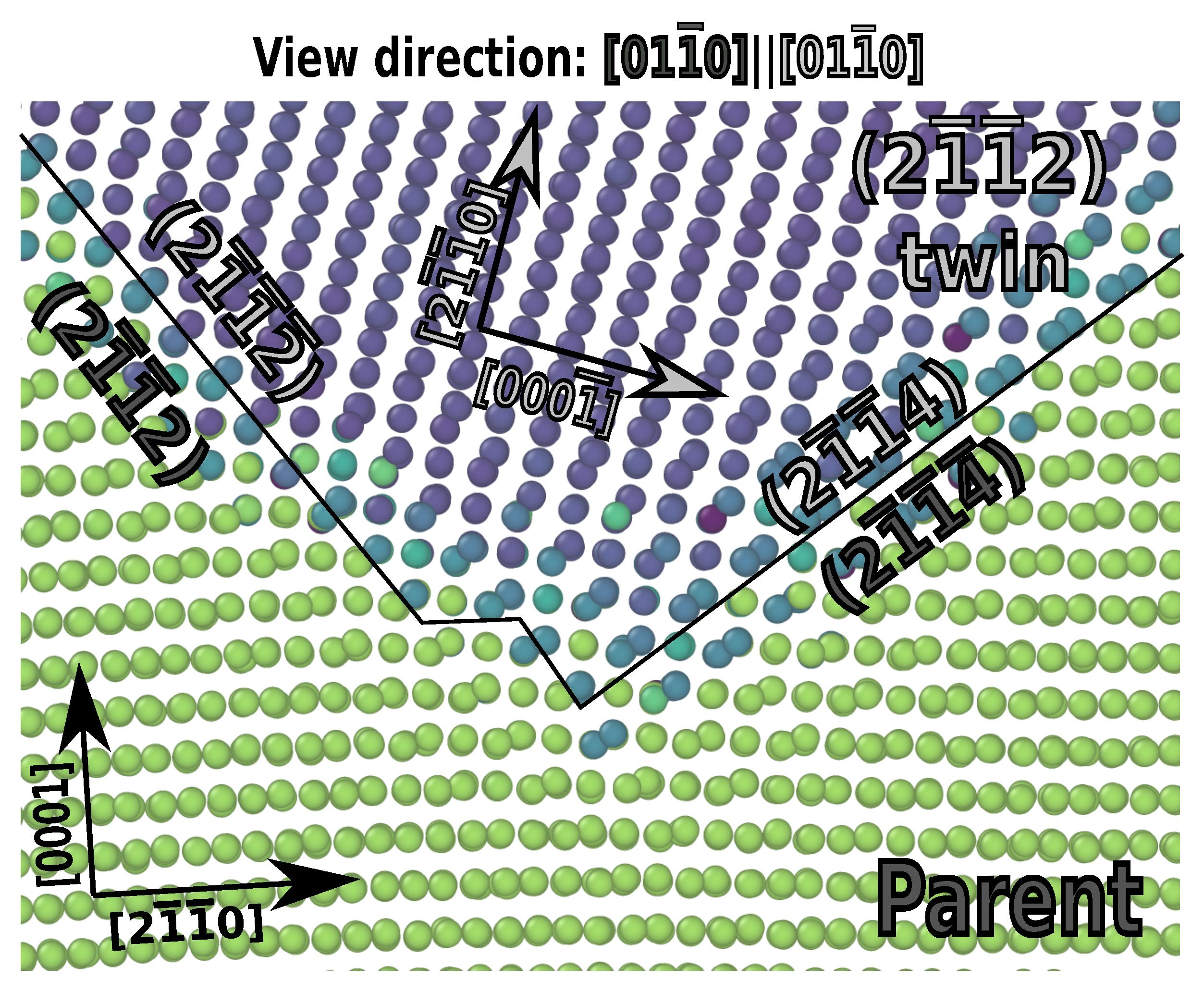
3.2.1. The {2111}{0001} Facet
According to Morrow et al. [4] and Wang et al. [10], the {1122} twin facets onto the {0001}{2112} asymmetric tilt boundary. This, however, conflicts with the lattice correspondence for {1122} twinning, which prescribes that the {0001}{2111} facet should be produced.
There are at least two possibilities for these unusual facets: either they are formed by a different process of facet nucleation, which can be achieved by emitting lattice dislocations as the facet is formed, or they are formed from the pile-up of four-layer disconnections, which easily form short {0001}{2112} facets unlike the observed three-layer disconnections. The facet appears to lie exactly between {0001}{2112} and {0001}{2111}, differing 7 from both of them. This is mainly a result of it being too short to easily characterize.
Examination of the facet lengths in Morrow et al. [4] indicate that two of them are in length while the longest is long. Thus, the lengths correspond closely to pile-up of two and three disconnections three-layer disconnections, respectively, but do not match well with an integer multiple of the minimum {0001}{2112} facet length. There are also other issues with the possibility of {0001}{2112} nucleation: the four-layer disconnection has an opposite sense of shear from that of the three-layer disconnection and would accommodate 〈c〉-axis tension, as was noted by Wang et al. [10].
In our molecular dynamics results, {2111}{0001} and {0001}{2111} facets were initially produced as shown in Figure 3. However, the interface structure was highly distorted, and in one case, a 〈2023〉/6 dislocation was emitted leaving an fault trailing to the interface and leaving the interface structure somewhat closer to {2111}{0001}. Thus, we hypothesize that the {2111}{0001} facet forms conservatively as with other observed facets but is unstable and decomposes into {2112}{0001} by interacting with lattice dislocations, which induce rotation of the interface plane from {2111}{0001}.
The vector is taken to be [2116]/3. = (2111). From the lattice correspondence, = [2110] and = (0001). = [0110] since this is a tilt facet. We find that . This gives the following:
Selecting = [4223]/3, with a corresponding lattice vector = [4223]/3, we find that the disconnection transforms to:
In coordinates aligned with the interface such that = [0110] and = , this is represented as:
Choosing different values of will generally lead to results that are either equal to or integer multiples of or as given above.
3.2.2. The {2118}{2110} Facet Interface
We use the same twin variant (2112) and thus the same lattice correspondence matrix and rotation matrix. The {2118}{2110} facet was observed using both potentials in our simulation results as shown in Figure 4.
As with the {2111}{0001} facet, this one is presumed to be unstable and spontaneously decompose into {2116}{2110}, which was observed by Wang et al. [10].
Proceeding with the analysis as above, is taken to be [8443]/3, remains [0110] and = (2118). The lattice correspondence gives = (2110). , which gives the rotation and strain matrices as:
Disconnection transformation onto the new facet is computed using the value = [1100]. From the lattice correspondence, = [1123]. We find that the disconnection transforms to:
In coordinates aligned with the interface such that = [0110] and = , this is represented as:
3.2.3. The 2114 Twin Facet
Using geometric considerations alone, every hcp twin may produce a facet onto its conjugate twin interface. However, energetic considerations may prevent some of these possible facets from forming. This facet is shown in Figure 5.
Proceeding with the analysis as above, is taken to be [4223]/3, remains [0110] and = (2114). The lattice correspondence gives = [2114]. , and this is very large for facet formation. The facet formation elastic energy scales with the disclination strength squared [58]. This may be why the facet is not observed with the RANN potential. Experimental validation would be needed to determine whether a facet with such high distortion can actually form. The rotation and strain matrices are:
As expected, the computation shows no in-plane strain on the new twin interface.
Disconnection transformation onto the new facet is computed using the value = [1100]. From the lattice correspondence, = [1123]. We find that the disconnection transforms to:
In coordinates aligned with the interface such that = [0110] and = , this is represented as:
The Burgers vector has no component in this reference because there is no in-plane strain. This is the standard twinning vector for [2114] twins.
3.3. Faceting on the {1121} Boundaries
The Burgers vector direction is [2116]. The lattice correspondence matrix is:
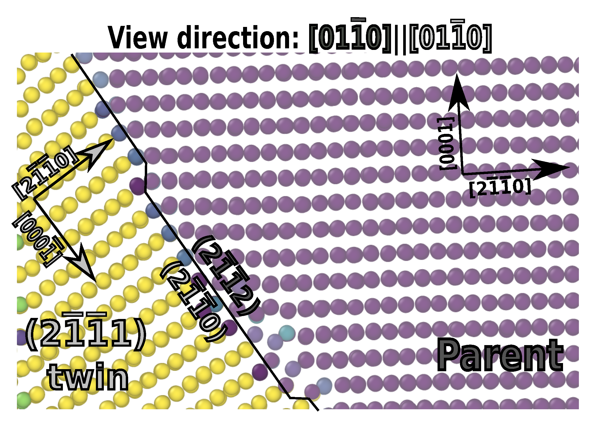
The {1122}{1120} Facet Interface
We use the values = [1210], = [1213]/3 and [0110]. The {2110}{2112} facet was observed using both potentials in our simulation results as shown in Figure 6.
Proceeding with the analysis as above, is taken to be [2113]/3, remains [0110] and = (2112). The lattice correspondence gives = (2110). , which gives the rotation and strain matrices as:
Disconnection transformation onto the new facet is computed using the value = [1110]. From the lattice correspondence, = [1010]. We find that the disconnection transforms to:
In coordinates aligned with the interface such that = [0110] and = , this is represented as:
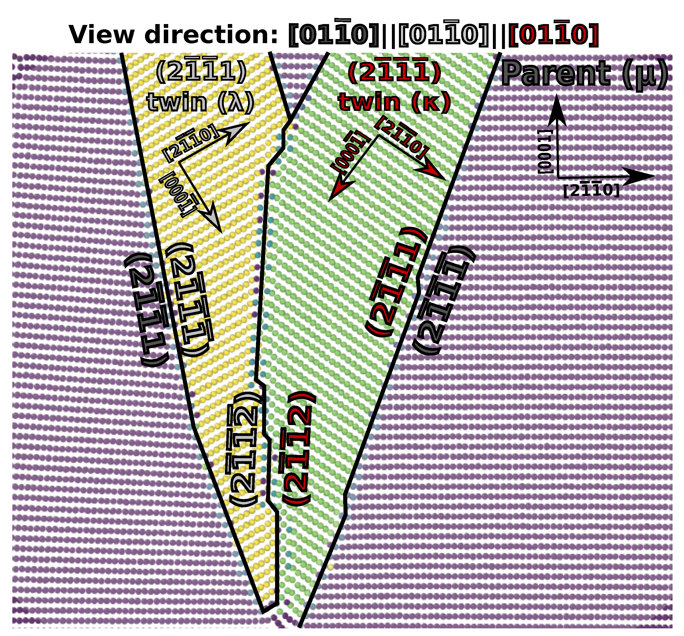
3.4. {1121} Twin–Twin Interactions
As seen in our results, the two cozonal {1121} twin variants readily interact to form an interface, which appears to be the {1122} twin. Similarly, we found a double twin, {1121} within {1122}, which forms a {1121} interface with the parent. Using the mathematics described above, these reactions can be explicitly quantified, confirming that the standard {1122} twin interface is produced by two interacting {1121} twins. The twin–twin interaction is depicted in Figure 7.
By inspecting the figure, we may identify the vectors: and , which span the new interface. One of these is the axis = = = [0110], which is common to the parent and both twins. The other vector is = [0001]. In some cases, it may be more practical to first identify or and use the lattice correspondence matrix to derive . The interface normal direction in is computed as [2110]/3. The specific variants of {1121} twinning active in Figure 7 are (2111) in green and (2111) in yellow. The lattice correspondences for these twins are:
The rotation matrices are:
Computing the interface normal directions using these matrices, we find:
From these, we find that the triple point disclination has a strength: . If the normal direction is rotated into a reference frame: and then converted back into a four-index plane, the plane coordinates (-2112) are produced. Likewise, doing the same in produces (2112). This, along with the axis of [0110] lying in the interface with the same indices in coordinate systems aligned with either twin, confirms that the interaction produces a (-2112) twin.
Finding is the next step; in this case, it is trivial: = [0110]. With the angle and axis, we determine the local rotation matrices and and the interface coherency strains. As with the case of faceting onto the {1124} twin interface, coherency strains to produce this twin interface may be explicitly computed to be nil.
If we consider a twinning disconnection, moving on the interface toward the triple point, multiple reaction values are possible depending upon the selection of , much like in the case of faceting. We observed the movement of the triple point by the disclination dipole reacting with incoming disclinations. A couple of different cases are noteworthy. First, we consider the case: = [0001]. From this, we obtain:
This vector represent a disconnection coming from the twin interface, which moves the triple point in the positive z direction and emits a twinning disconnection on the interface. Thus, the new twin–twin interface is grown by this process. The total defect content left on the interface is nil.
Secondly, we consider a probe vector of [1210]/3. From this, we obtain:
This vector represents the triple point moving to the right by absorbing a disconnection coming from the twin interface and emitting disconnections on the and interfaces. Notably, the produced disconnection on the interface is not the standard twinning disconnection. Rather, it has a step height one third the standard value and a Burgers vector substantially larger and with the opposite sense of shear. Since this disconnection is not observed experimentally, we hypothesize that any geometric reactions that produce it are energetically suppressed. Our simulations support this hypothesis as the triple points for this twin–twin interaction are uniformly seen to move up and down, along the 〈c〉 direction, however, never in any other direction.
The failure to produce an active defect on the interface is also reflected in that the lattice correspondence matrix as produced by Equation (28) does not match the one produced for (2112) twinning by Equation (9):
The lattice correspondence produced by double twinning corresponds exactly to a {1122} one-layer disconnection, which is observed by some atomistic potentials but does not match the experimental results.
3.5. {1121}-{1012} Twin Interactions
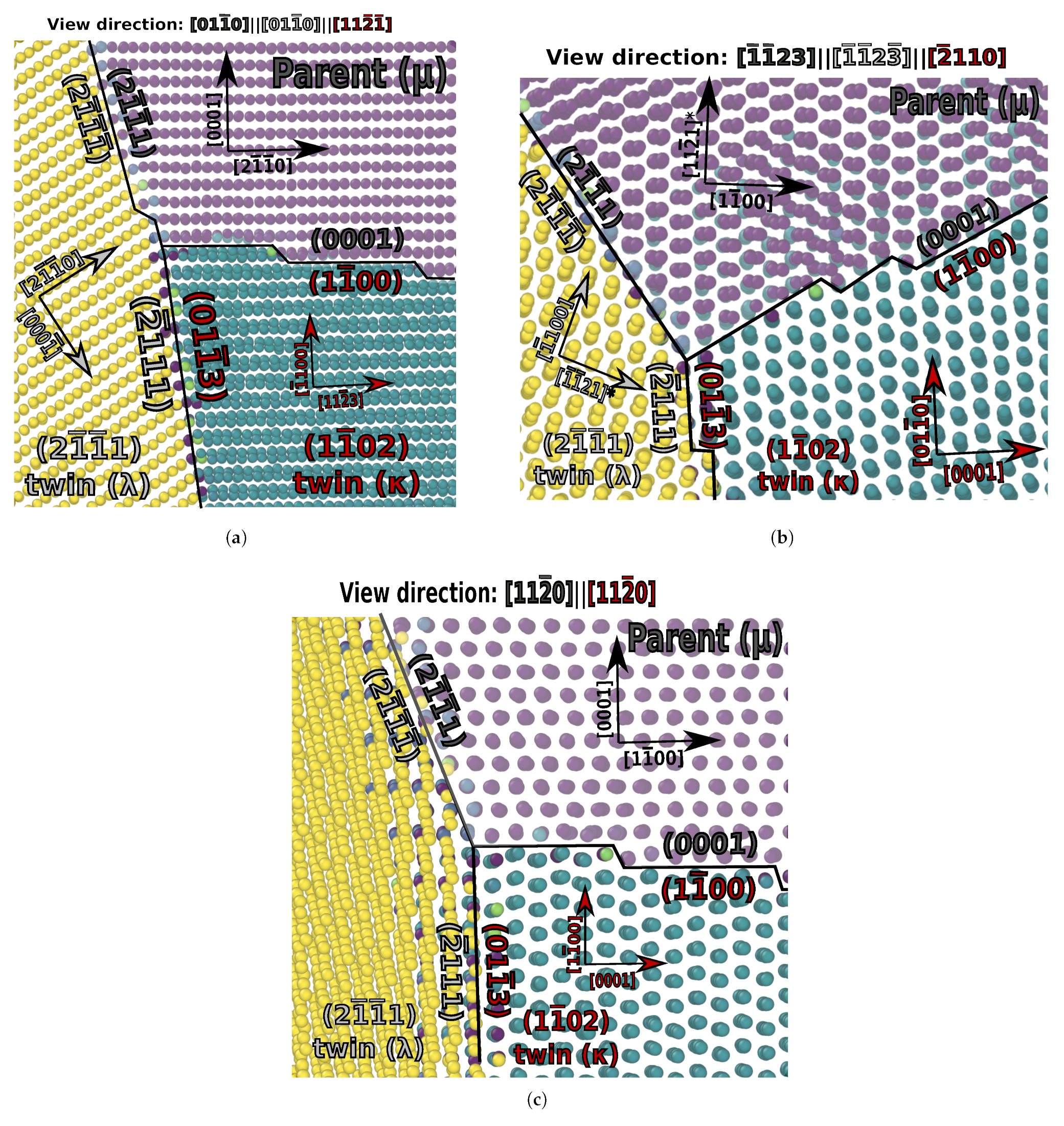
Unlike the previous results, {1121}-{1012} interactions are fully three-dimensional and thus more challenging to analyze. Nevertheless, the mathematical framework was derived for fully 3D interactions so the process proceeds similarly to above. Figure 8 shows an interaction between a (2111) twin and a (1102) twin.
By observation of Figure 8, the vectors = [0110] and = [1123]/3 are chosen. The lattice correspondences and rotation matrices are given by:
From these, we find the interface normal directions:
These correspond to the (2111) and (0110) planes, respectively. The disclination strength, which is the angle between these plane normals, is . The axis is computed by Equation (24), and thus the rotation matrices become:
Since the (2111) and (0110) planes are not coherent, finite in-plane strains will be produced as computed by Equation (26):
We consider a couple of different possible disconnection reactions at this twin–twin interface. First, we select = [1123]/3.
This indicates that an incoming disconnection on the (1102) interface can extend the twin–twin interface, leaving no products behind on the twin–twin interface or the (2111) twin interface.
Secondly, we select = [0001].
This reaction shows that a disconnection from the (2111) interface may react at the triple point to form defects in both the (1102) twin interface and the twin–twin interface. According to our simulation results, this defect in the twin–twin interface appears to be glissile.
3.6. {1121}-{1012} Double Twinning
Similarly to the case above, we observed {1012} twinning within a {1121} twin. The specific variants were (2111) and (1102) and are shown in Figure 9.
The lattice correspondence and rotation matrices from to are given by:
By inspecting the figure, it is clear that the double twin interface with the parent is near the (2111) plane of the initial twin. However, the local structure appears to be aligned along (2112) with steps, which bring it to roughly (4-1-13) overall. As with other twin–twin interactions, a disclination dipole is produced with poles at either end of the new interface and local strain and rotation to bring the interface into coincidence. We use = (2112), which corresponds to = (1126) and = (2110). The interface is spanned by the vectors = [2113]/3 and = [0110]. This produces disclination rotations with an angle of . The rotation matrix and in-plane strains are:
We consider a couple possible disconnection reactions. First, using = [2113]/3, the following disconnections are obtained:
Thus, a disconnection on (2111) can react at the double twin interface junction, emit a disconnection on the (1102) twin interface inside the (2111) twin and lengthen the double twin interface producing no defect on that interface.
Considering also the probe vector , we obtain the following reaction:
In this reaction, is two times the (2111) twinning disconnection. Likewise, is equal to the (1102) twinning disconnection, when viewed from the orientation. Thus, this probe vector indicates that two incoming disconnections on the (2111) twin interface can react at the double twin interface, producing a a step on the double twin interface with the parent and a step on the (1102) interface inside the (2111) twin. These steps appears to be glissile in our simulations.
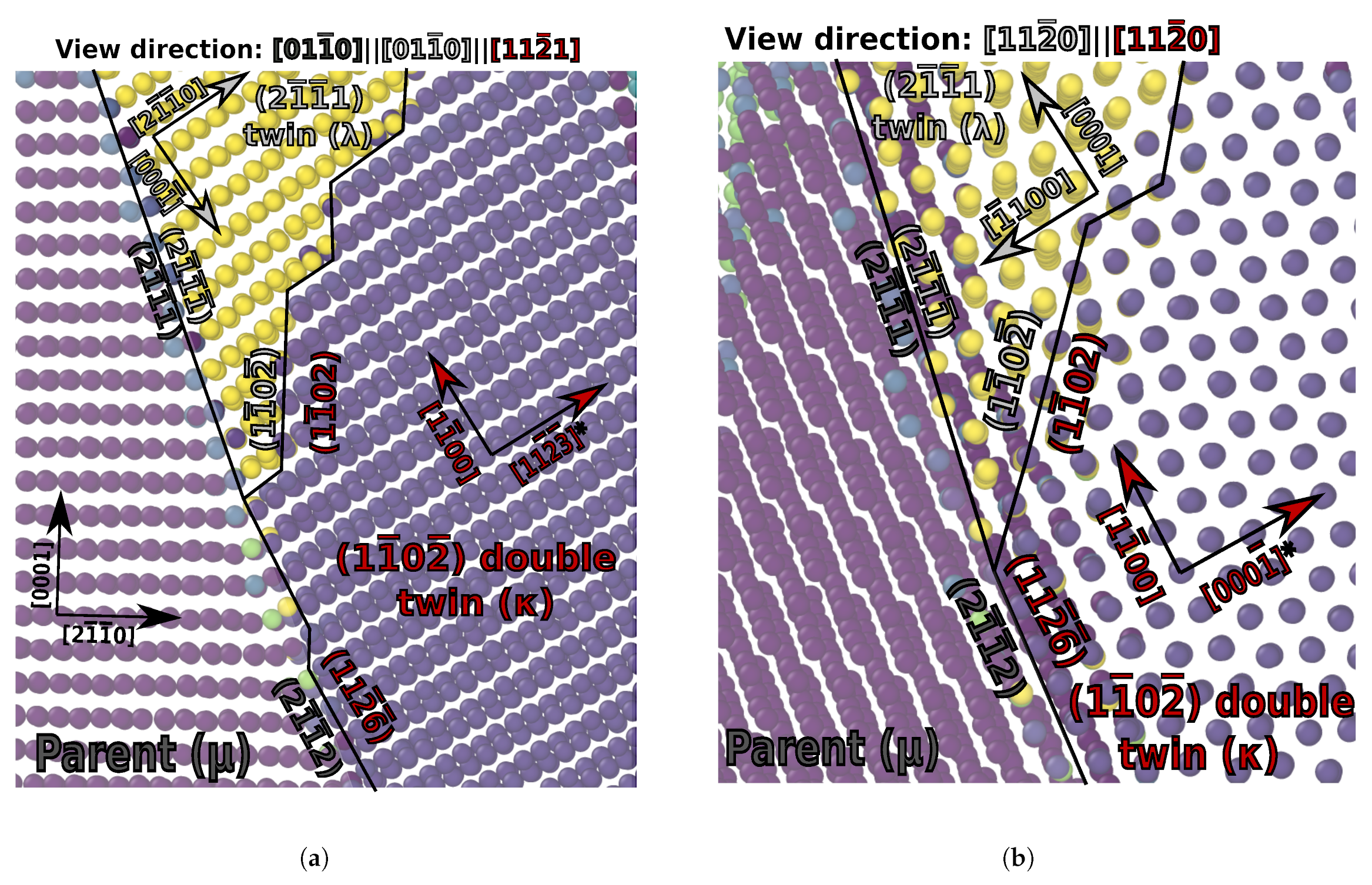
3.7. Interaction between {1121}-{1012} Double Twin and {1012} Twin
Further complicating matters, the observed double twin in our simulation interacted with the (1102) twin in the parent. Above we described the interaction between this (1102) twin and the (2111) twin. Now, we characterize the interaction between the same (1102) twin and the double twin. Since the (2111) twin is not involved in this interaction anymore since it has re-twinned, our notation will be for the parent, for the double twin and for the (1102) twin of the parent. Figure 10 shows the interaction between the double and single twins.
Remarkably, as identifiable in the figure, the double twin and single twin together produce a {1013} twin boundary. The lattice correspondence for this boundary does not match the normal {1013} twin boundary—it has additional shear and a different twinning direction.
As with the {1011} twin, the (0113) twin has two types of active disconnections. A four-layer disconnection, which provides shear in the [0332] direction, and a two-layer disconnection, which provides the same shear with an additional shearing in the ±[2110] direction. The four-layer disconnections have been observed to dissociate into two dislocations, which have the step height of two planes. Successive motion of these smaller disconnections with opposite axial components enable the axial shear to be fully compensated and the observed twinning shear and direction to be achieved overall [59]. In particular, the four-layer Burgers vector is:
and the two-layer disconnection is:
Upon further investigation, the shear computed for migration of the boundary produced by the interacting (1102) twin and (2111)-(1102) double twin matches that for the two-layer twinning disconnection active on the {0113} boundary. In the case of this compound reaction, however, the combined shears from all of the active twins produces a mobile {0113} twin interface with these two-layer steps, however, without the possibility for a two-layer step with the opposite axial sense. Thus, the observed shear and twinning direction are different from a normal {1013} twin.
To analyze the new interface, we choose the vectors = [0110] and [1213]/3. The lattice correspondence and rotation matrices are given by:
From these, we find that the interface normal directions become in Miller–Bravais coordinates: = (0113) and = (0113). The disclination strength is . The axis is given by:
which produces rotation matrices as specified in Equation (6). The in-plane strains for this interface are nil, as expected since a twin interface is formed.
Considering the behavior of a few probe vectors, we can identify some possible disconnection reactions. First, using = [0220]:
This indicates that a disconnection on the (1102) twin interface can react, moving the triple point but producing no product disconections.
Secondly, we example a probe vector [0002]:
This reaction shows a disconnection on the double twin interface (matching the one obtained in Equation (70)) reacting with two twinning disconnections on the (1102) twin of the parent to produce a new disconnection on the novel {1013} twin interface. The new burgers vector and step height match exactly that of the previously reported two-layer disconnection in Equation (75) when it is rotated to the same reference orientation.
4. Conclusions
In summary, in this work, simulations studying twin–twin interactions at the atomic scale were conducted and analyzed in detail. In order to fully analyze complex twin interaction interfaces at the atomic scale, interfacial defect theory was employed and extended to accurately assess finite strain effects in three dimensions. To our knowledge, an explicit geometrical theory of interfacial defect behavior during twin–twin interactions had not been previously derived. The mathematics of facet reactions was also rederived in a fully three-dimensional framework, thereby, enabling the analysis of non-tilt facets. Some specific findings were as follows:
- {1121} co-zonal twins readily react to form a {1122} twin boundary. However, the boundary formed in this manner has limited mobility because the triple points cannot conservatively move normal to the initial interface plane without the emission of 〈c+a〉 dislocations.
- {1121} twins faceted onto the {1120}{1122} interface in agreement with the experimental findings.
- {1122} twins faceted onto the {0001}{1121} facet. This disagreed with experimental reports of the {0001}{1122} facet; however, according to interfacial defect theory, the lattice correspondence requires that the former be the facet produced.
- {1122} twins also faceted onto the {1120}{1128} facet and the {1124} twin boundary. The latter of these agrees with previous observations that all twins appear to be able to facet onto their conjugate, which shares the same axis and shear.
- Compound twin–twin interactions were observed, including one case where a double twin (1121}-{1102) interacted with a single twin, (1012), to form a new mobile twin boundary: {1013}. Cases where twins within twins lead to a highly mobile ordered boundary like this were not anticipated, however, may have significant implications for plasticity under highly strained conditions.
Author Contributions
Conceptualization, C.B.; methodology, C.B., J.M. and M.N.; software, C.B., J.M. and M.N.; validation, C.B., J.M. and M.N.; formal analysis, C.B.; investigation, J.M. and M.N.; data curation, C.B.; writing—original draft preparation, C.B.; writing—review and editing, C.B., J.M. and M.N.; visualization, C.B. and J.M.; supervision, C.B.; project administration, C.B.; funding acquisition, C.B. All authors have read and agreed to the published version of the manuscript.
Funding
The research described and the resulting data presented herein, unless otherwise noted, was funded under PE 0602784A, Project T53 “Military Engineering Applied Research”, Task 7 under Contract No. W56HZV-17-C-0095, managed by the U.S. Army Combat Capabilities Development Command (CCDC) and the Engineer Research and Development Center (ERDC).
Institutional Review Board Statement
Not applicable.
Informed Consent Statement
Not applicable.
Data Availability Statement
Data and code used to generate the RANN Ti potential are available at https://github.com/ranndip/project_page.
Acknowledgments
The work described in this document was conducted at CAVS, Mississippi State University. Permission was granted by ERDC to publish this information.
Conflicts of Interest
The authors declare no conflict of interest.
References
- Dang, K.; Tomé, C.N.; Capolungo, L. The 1012 non-cozone twin–twin interactions in Mg: A stability and mobility study using 3-D atomistic simulations. Scr. Mater. 2021, 200, 113913. [Google Scholar] [CrossRef]
- Suh, B.C.; Kim, J.H.; Hwang, J.H.; Shim, M.S.; Kim, N.J. Twinning-mediated formability in Mg alloys. Sci. Rep. 2016, 6, 1–8. [Google Scholar] [CrossRef] [PubMed] [Green Version]
- Song, B.; Guo, N.; Liu, T.; Yang, Q. Improvement of formability and mechanical properties of magnesium alloys via pre-twinning: A review. Mater. Des. 2014, 62, 352–360. [Google Scholar] [CrossRef]
- Morrow, B.; McCabe, R.; Cerreta, E.; Tomé, C. Observations of the Atomic Structure of Tensile and Compressive Twin Boundaries and Twin–Twin Interactions in Zirconium. Metall. Mater. Trans. A 2014, 45, 5891–5897. [Google Scholar] [CrossRef]
- Hirth, J.P. Dislocations, steps and disconnections at interfaces. J. Phys. Chem. Solids 1994, 55, 985–989. [Google Scholar] [CrossRef]
- Won, J.W.; Park, C.H.; Hong, J.; Lee, C.S.; Hong, S.G. Simultaneous Improvement in the Strength and Formability of Commercially Pure Titanium via Twinning-induced Crystallographic Texture Control. Sci. Rep. 2019, 9, 1–11. [Google Scholar] [CrossRef]
- Won, J.W.; Lee, J.H.; Jeong, J.S.; Choi, S.W.; Lee, D.J.; Hong, J.K.; Hyun, Y.T. High strength and ductility of pure titanium via twin-structure control using cryogenic deformation. Scr. Mater. 2020, 178, 94–98. [Google Scholar] [CrossRef]
- Wang, J.T.; Yin, D.L.; Liu, J.Q.; Tao, J.; Su, Y.L.; Zhao, X. Effect of grain size on mechanical property of Mg–3Al–1Zn alloy. Scr. Mater. 2008, 59, 63–66. [Google Scholar] [CrossRef]
- Yu, Q.; Wang, J.; Jiang, Y.; McCabe, R.J.; Li, N.; Tomé, C.N. Twin–twin interactions in magnesium. Acta Mater. 2014, 77, 28–42. [Google Scholar] [CrossRef]
- Wang, S.; Dang, K.; McCabe, R.J.; Capolungo, L.; Tomé, C.N. Three-dimensional atomic scale characterization of {112 2} twin boundaries in titanium. Acta Mater. 2021, 208, 116707. [Google Scholar] [CrossRef]
- Xu, B.; Capolungo, L.; Rodney, D. On the importance of prismatic/basal interfaces in the growth of 1012 twins in hexagonal close packed crystals. Scr. Mater. 2013, 68, 901–904. [Google Scholar] [CrossRef] [Green Version]
- Barrett, C.D.; El Kadiri, H. The roles of grain boundary dislocations and disclinations in the nucleation of {1012} twinning. Acta Materialia 2014, 63, 1–15. [Google Scholar] [CrossRef]
- Barrett, C.D.; El Kadiri, H. Fundamentals of mobile tilt grain boundary faceting. Scr. Mater. 2014, 84, 15–18. [Google Scholar] [CrossRef]
- Barrett, C.; Kadiri, H.E. The Deformation Gradient of Interfacial Defects on Twin-like Interfaces. In Magnesium Technology 2015; Springer: Cham, Switzerland, 2015; pp. 121–125. [Google Scholar] [CrossRef]
- Pond, R.C.; Hirth, J.P.; Serra, A.; Bacon, D.J. Atomic displacements accompanying deformation twinning: Shears and shuffles. Mater. Res. Lett. 2016, 4, 185–190. [Google Scholar] [CrossRef] [Green Version]
- Wang, J.; Liu, L.; Tomé, C.; Mao, S.; Gong, S. Twinning and de-twinning via glide and climb of twinning dislocations along serrated coherent twin boundaries in hexagonal-close-packed metals. Mater. Res. Lett. 2013, 1, 81–88. [Google Scholar] [CrossRef]
- Pond, R.; Nabarro, F. Dislocations in solids. VOL 1989, 8, 1–66. [Google Scholar]
- Pond, R. Dislocations and Properties of Real Materials. In Dislocations and Properties of Real Materials; Institute of Metals: London, UK, 1985; chapter Interfaces and dislocations; pp. 71–93. [Google Scholar]
- Pond, R.C.; Casey, S.M. Topological Theory of Line-Defects. In Equilibrium Structure and Properties of Surfaces and Interfaces; Springer: Boston, MA, USA, 1992; pp. 139–174. [Google Scholar] [CrossRef]
- Serra, A.; Pond, R.C.; Bacon, D.J. Computer simulation of the structure and mobility of twinning disclocations in HCP Metals. Acta Metall. Mater. 1991, 39, 1469–1480. [Google Scholar] [CrossRef]
- Serra, A.; Bacon, D.J. Computer simulation of twin boundaries in the h. c. p. metals. Philos. Mag. A 1986, 54, 793–804. [Google Scholar] [CrossRef]
- Serra, A.; Bacon, D.J. Computer simulation of screw dislocation interactions with twin boundaries in hcp metals. Acta Metall. Mater. 1995, 43, 4465–4481. [Google Scholar] [CrossRef]
- Serra, A.; Bacon, D.J.; Pond, R.C. Twins as barriers to basal slip in hexagonal-close-packed metals. Metall. Mater. Trans. A 2002, 33, 809–812. [Google Scholar] [CrossRef]
- Barrett, C.D.; El Kadiri, H. Impact of deformation faceting on and embryonic twin nucleation in hexagonal close-packed metals. Acta Mater. 2014, 70, 137–161. [Google Scholar] [CrossRef]
- Hirth, J.; Pond, R. Steps, dislocations and disconnections as interface defects relating to structure and phase transformations. Acta Mater. 1996, 44, 4749–4763. [Google Scholar] [CrossRef]
- Christian, J.W.; Mahajan, S. Deformation twinning. Prog. Mater. Sci. 1995, 39, 1–157. [Google Scholar] [CrossRef]
- Ostapovets, A.; Molnár, P. On the Relationship between the “Shuffling Dominated” and “Shear Dominated” Mechanisms for Twinning in Magnesium. Scr. Mater. 2013, 69, 287–290. [Google Scholar] [CrossRef]
- Ostapovets, A.; Gröger, R. Twinning disconnections and basal–prismatic twin boundary in magnesium. Model. Simul. Mater. Sci. Eng. 2014, 22, 025015. [Google Scholar] [CrossRef]
- Yu, S.; Liu, C.; Gao, Y.; Jiang, S.; Chen, Z. A rotation-shear model on the atomic motion during {1012} twinning in magnesium alloys. Mater. Lett. 2016, 165, 185–188. [Google Scholar] [CrossRef]
- El Kadiri, H.; Barrett, C.D.; Wang, J.; Tomé, C.N. Why are twins profuse in magnesium? Acta Mater. 2015, 85, 354–361. [Google Scholar] [CrossRef] [Green Version]
- Wang, F.; Barrett, C.D.; McCabe, R.J.; Kadiri, H.E.; Capolungo, L.; Agnew, S.R. Dislocation induced twin growth and formation of basal stacking faults in {1012} twins in pure Mg. Acta Mater. 2019, 165, 471–485. [Google Scholar] [CrossRef]
- Gong, M.; Liu, G.; Wang, J.; Capolungo, L.; Tomé, C.N. Atomistic simulations of interaction between basal〈 a〉 dislocations and three-dimensional twins in magnesium. Acta Mater. 2018, 155, 187–198. [Google Scholar]
- Wang, J.; Beyerlein, I.; Hirth, J. Nucleation of elementary and twinning dislocations at a twin boundary in hexagonal close-packed crystals. Model. Simul. Mater. Sci. Eng. 2012, 20, 024001. [Google Scholar] [CrossRef]
- Reed-Hill, R.; Buchanan, E. Zig-zag twins in zirconium. Acta Met. 1963, 11. [Google Scholar] [CrossRef]
- Oppedal, A.L.; El Kadiri, H.; Tomé, C.N.; Kaschner, G.C.; Vogel, S.C.; Baird, J.C.; Horstemeyer, M.F. Effect of dislocation transmutation on modeling hardening mechanisms by twinning in magnesium. Int. J. Plast. 2012, 30–31, 41–61. [Google Scholar] [CrossRef]
- El Kadiri, H.; Kapil, J.; Oppedal, A.; Hector Jr, L.; Agnew, S.R.; Cherkaoui, M.; Vogel, S. The effect of twin–twin interactions on the nucleation and propagation of {1012} twinning in magnesium. Acta Mater. 2013, 61, 3549–3563. [Google Scholar] [CrossRef]
- Jiang, L.; Jonas, J.J.; Luo, A.A.; Sachdev, A.K.; Godet, S. Influence of {1012} extension twinning on the flow behavior of AZ31 Mg alloy. Mater. Sci. Eng. A 2007, 445, 302–309. [Google Scholar] [CrossRef]
- Cahn, R.W. Soviet work on mechanical twinning. Il Nuovo Cimento (1943–1954) 1953, 10, 350–386. [Google Scholar] [CrossRef]
- Barrett, C.; El Kadiri, H.; Tschopp, M. Breakdown of the Schmid law in homogeneous and heterogeneous nucleation events of slip and twinning in Magnesium. J. Mech. Phys. Solids 2012, 60, 2084–2099. [Google Scholar] [CrossRef]
- Hennig, R.G.; Lenosky, T.J.; Trinkle, D.R.; Rudin, S.P.; Wilkins, J.W. Classical potential describes martensitic phase transformations between the α, β, and ω titanium phases. Phys. Rev. B 2008, 78, 054121. [Google Scholar] [CrossRef] [Green Version]
- El Kadiri, H.; Barrett, C.; Tschopp, M. The candidacy of shuffle and shear during compound twinning in hexagonal close-packed structures. Acta Mater. 2013, 61, 7646–7659. [Google Scholar] [CrossRef] [Green Version]
- Dickel, D.; Barrett, C.D.; Carino, R.L.; Baskes, M.I.; Horstemeyer, M.F. Mechanical instabilities in the modeling of phase transitions of titanium. Model. Simul. Mater. Sci. Eng. 2018, 26, 065002. [Google Scholar] [CrossRef]
- Nitol, M.S.; Dickel, D.E.; Barrett, C.D. Machine learning models for predictive materials science from fundamental physics: An application to titanium and zirconium. Acta Mater. 2021, 224, 117347. [Google Scholar] [CrossRef]
- Plimpton, S. Fast parallel algorithms for short-range molecular dynamics. J. Comput. Phys. 1995, 117, 1–19. [Google Scholar] [CrossRef] [Green Version]
- Stukowski, A. Visualization and analysis of atomistic simulation data with OVITO—The Open Visualization Tool. Model. Simul. Mater. Sci. Eng. 2010, 18, 015012. [Google Scholar] [CrossRef]
- Dickel, D.; Nitol, M.; Barrett, C.D. LAMMPS implementation of rapid artificial neural network derived interatomic potentials. Comput. Mater. Sci. 2021, 196, 110481. [Google Scholar] [CrossRef]
- Baskes, M.I.; Johnson, R.A. Modified embedded atom potentials for HCP metals. Modell. Simul. Mater. Sci. Eng. 1994, 2, 147–163. [Google Scholar] [CrossRef]
- Nitol, M.S.; Mun, S.; Dickel, D.E.; Barrett, C.D. Unraveling Mg 〈c + a〉 slip using neural network potential. Philos. Mag. 2022, 102, 651–673. [Google Scholar] [CrossRef]
- Nitol, M.S.; Dickel, D.E.; Barrett, C.D. Artificial neural network potential for pure zinc. Comput. Mater. Sci. 2021, 188, 110207. [Google Scholar] [CrossRef]
- Hirth, J.P.; Lothe, J. Theory of Dislocations; John Wiley & Sons: Hoboken, NJ, USA, 1982. [Google Scholar]
- Balluffi, R.W. Introduction to Elasticity Theory for Crystal Defects; World Scientific Publishing Company: Singapore, 2016. [Google Scholar]
- Ostapovets, A.; Serra, A.; Pond, R.C. Non-diffusional growth mechanism of I1 basal stacking-faults inside twins in hcp metals. Scr. Mater. 2019, 172, 149–153. [Google Scholar] [CrossRef]
- Christian, J.W. The Theory of Transformations in Metals and Alloys: Part I + II; Elsevier: Amsterdam, The Netherlands, 2002; p. 933. [Google Scholar]
- Niewczas, M. Lattice correspondence during twinning in hexagonal close-packed crystals. Acta Mater. 2010, 58, 5848–5857. [Google Scholar] [CrossRef]
- Serra, A.; Bacon, D.J. Computer simulation of twinning dislocation in magnesium using a many-body potential. Philos. Mag. A 1991, 63, 1001–1012. [Google Scholar] [CrossRef]
- Serra, A.; Bacon, D.; Pond, R. A comment on B. Li, H. El Kadiri and MF Horstemeyer ‘Extended zonal dislocations mediating twinning in titanium’. Philos. Mag. 2013, 93, 3495–3503. [Google Scholar] [CrossRef]
- El Kadiri, H.; Barrett, C.D. Comments on “extended zonal dislocations mediating twinning in titanium”. Philos. Mag. 2013, 93, 3491–3494. [Google Scholar] [CrossRef]
- Romanov, A.; Kolesnikova, A. Application of disclination concept to solid structures. Prog. Mater. Sci. 2009, 54, 740–769. [Google Scholar] [CrossRef]
- Wang, J.; Beyerlein, I.; Hirth, J.; Tomé, C. Twinning dislocations on {1 011} and {1 013} planes in hexagonal close-packed crystals. Acta Mater. 2011, 59, 3990–4001. [Google Scholar] [CrossRef]
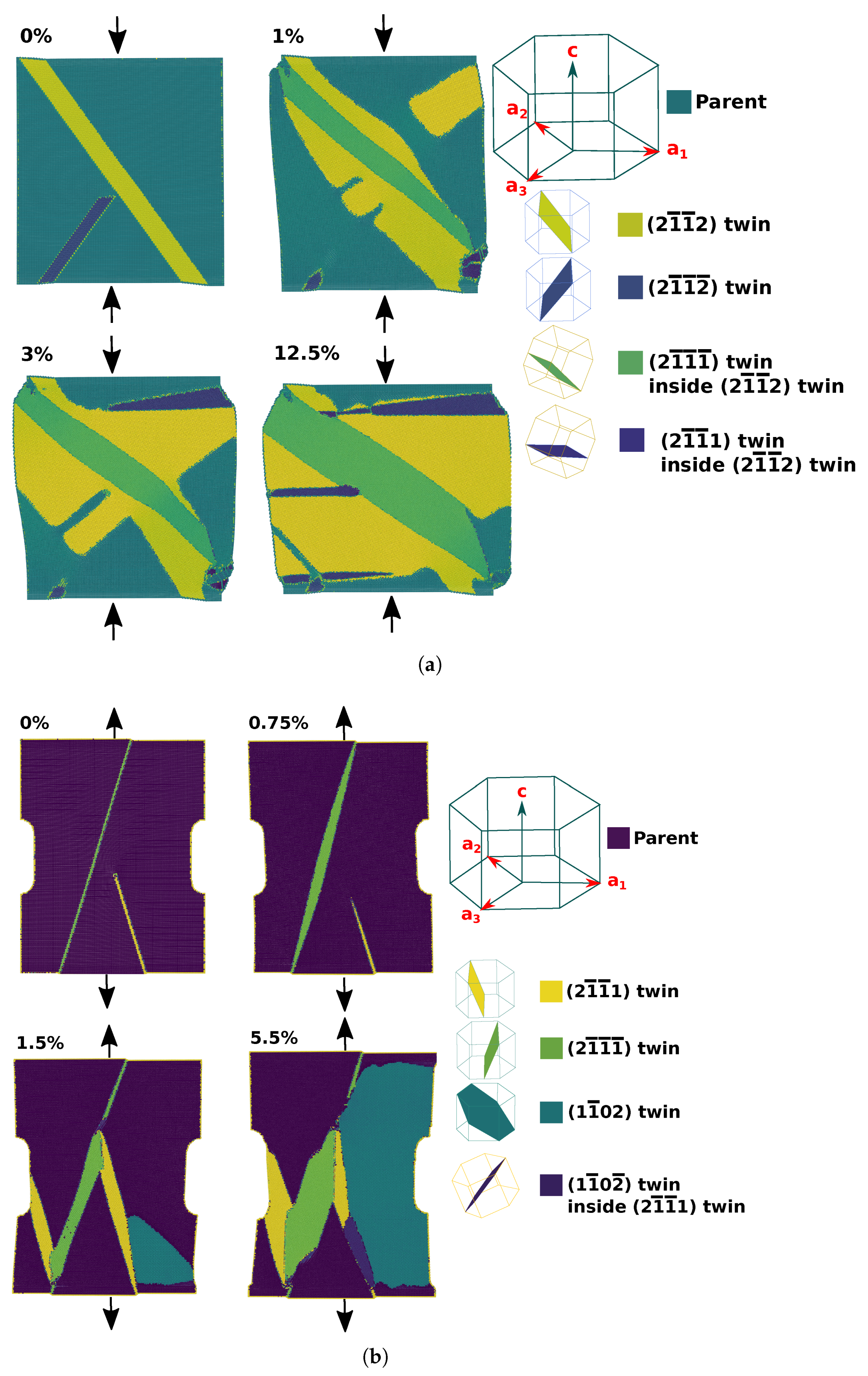
Figure 1.
Depiction of the initial setups. (a) Compression twin setup with inserted 4.3 nm{2112} twin band and 2 nm {2112} twin embryo. The compression evolution is depicted at 0%, 1%, 3% and 12.5% compression. (b) Tension twin setup with inserted 1 nm {2111} twin band and {2111} twin embryo. The tension evolution is depicted at 0, 0.75%, 1.5% and 5.5% tension. These frames were selected since they show most of the interactions found in the microstructural evolution of the tension and compression cases here studied. The MEAM/spline potential was used here; however, the results from that RANN potential were similar.

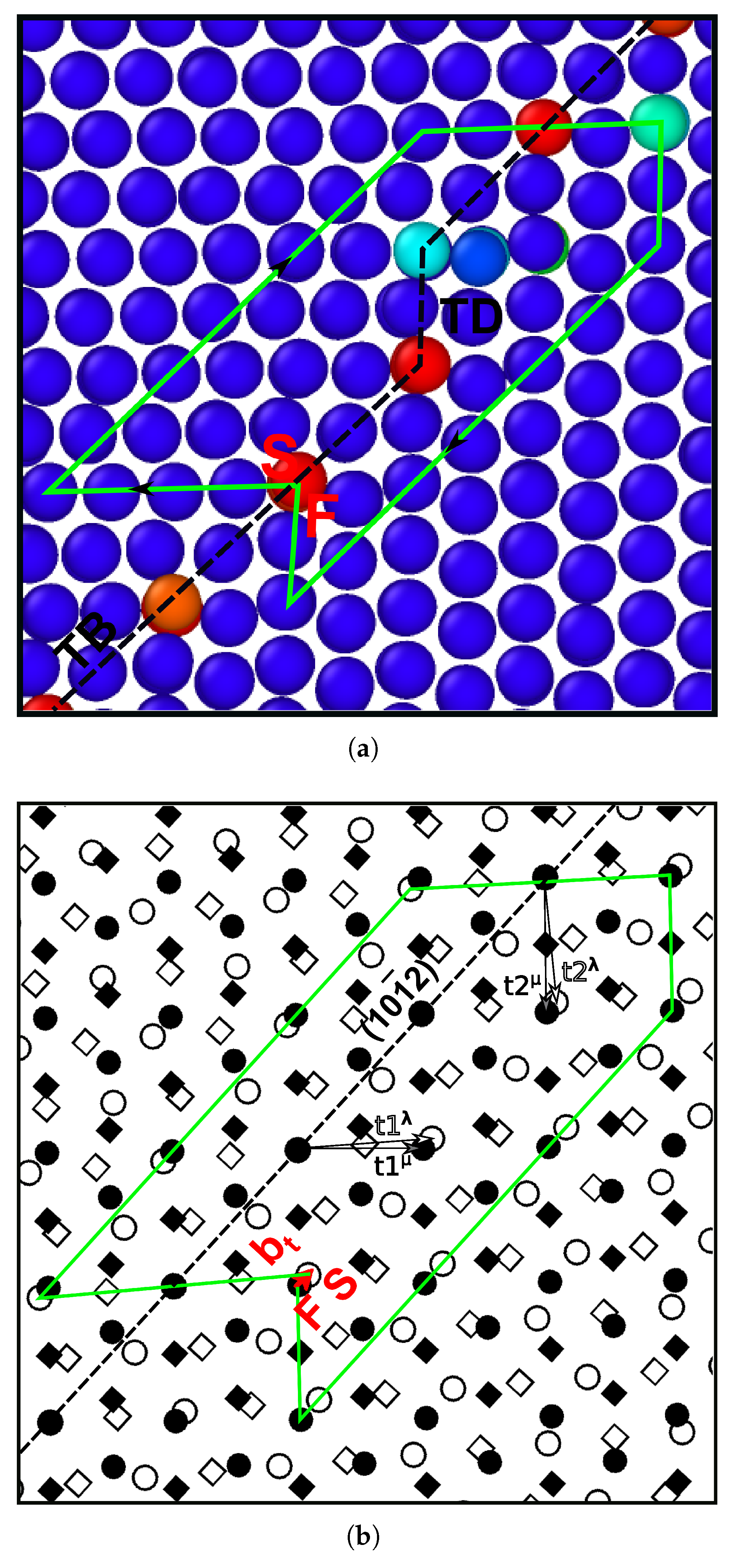
Figure 2.
Disconnection identification in the {1012} twin interface in Ti. (a) A closed circuit is constructed around the interface defect. (b) Using a reference pattern showing the lattice positions from both crystals coinciding at the original interface position, a reference circuit with closure failure is constructed. The closure failure gives the Burgers vector and step height of the disconnection.

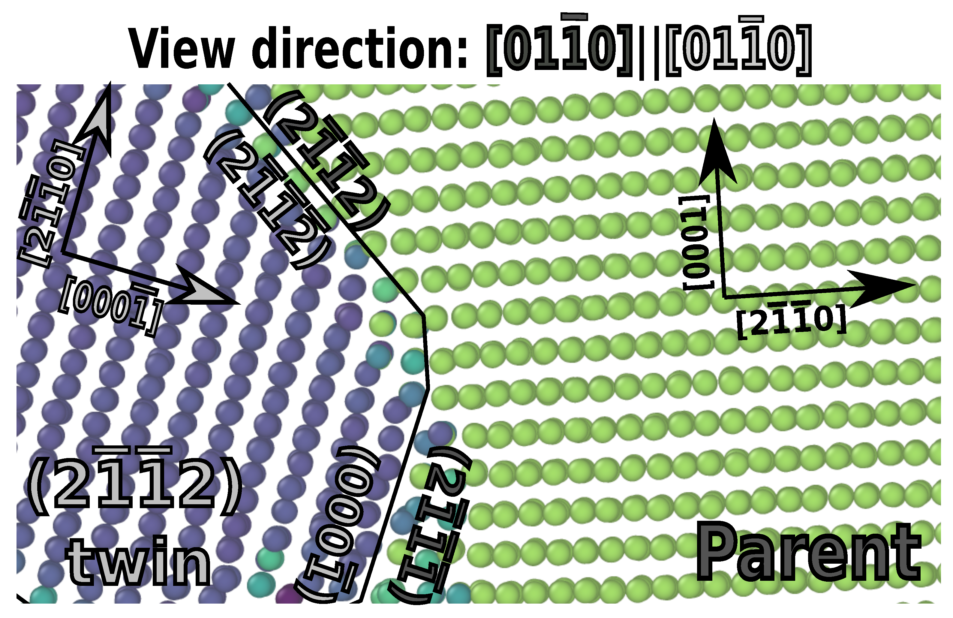
Figure 3.
Facet between the (2111) plane of the parent and the (0001) plane of the twin. The (2112) twin plane interface is also visible in the upper portion of the figure.
Figure 3.
Facet between the (2111) plane of the parent and the (0001) plane of the twin. The (2112) twin plane interface is also visible in the upper portion of the figure.

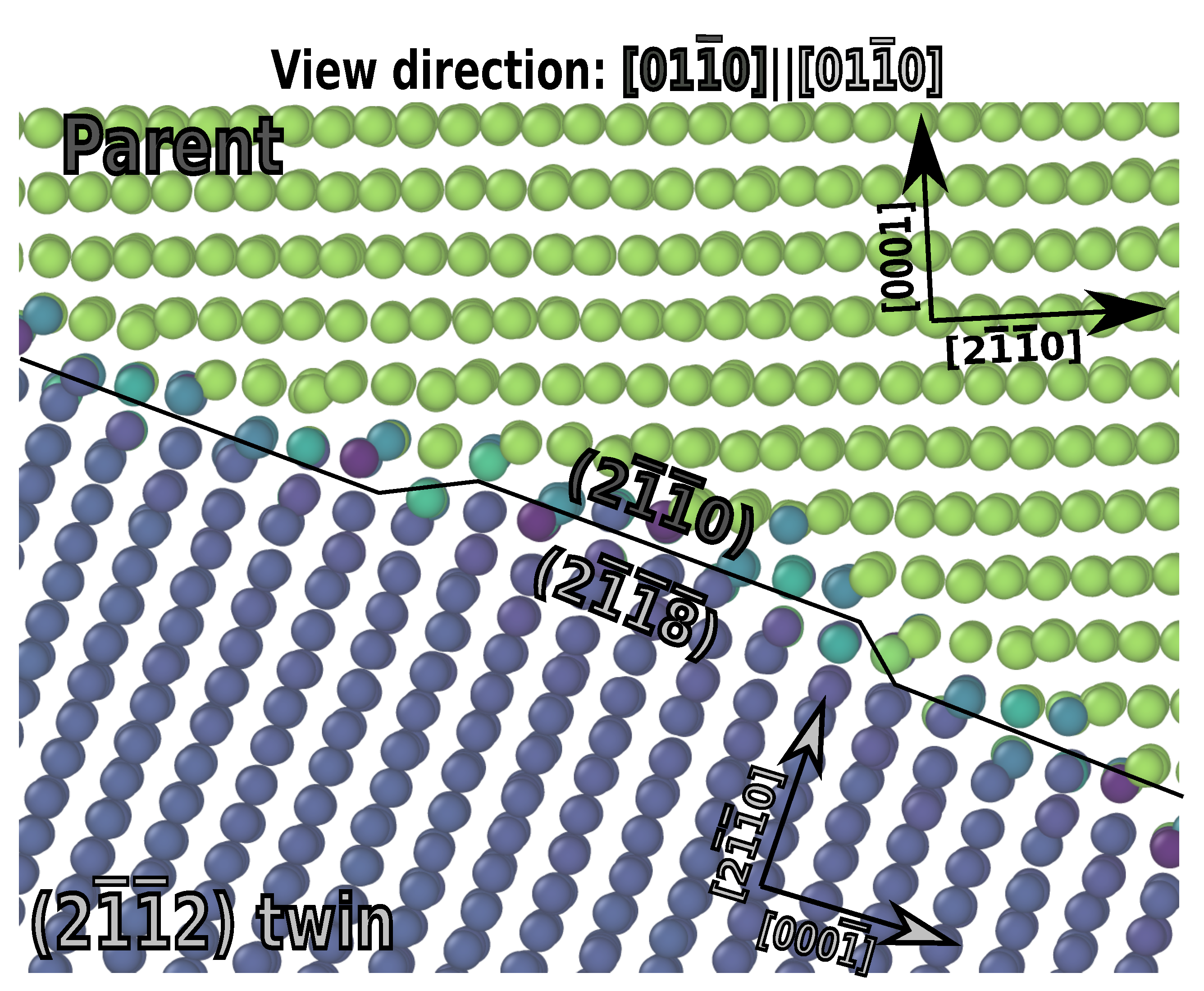
Figure 4.
(2112) facet onto the (2118)(2110) interface. A mobile one-layer step is visible on the interface.
Figure 4.
(2112) facet onto the (2118)(2110) interface. A mobile one-layer step is visible on the interface.

Figure 5.
(2112) facet producing (2114) twin interface. The facet disclination is large, thereby, producing evident distortion of the parent lattice orientation. The interface produced by the MEAM/spline potential for the (2112) and (2114) interfaces sometimes showed significant distortion during twin-growth reminiscent of the to phase transition.

Figure 6.
(2111) twin facet onto (2112)(2110). A one layer step is visible in the interface.

Figure 7.
Twin–twin interaction between co-zonal (2111) (yellow) and (2111) (green) twins. The twin–twin interface was a (2112) twin boundary, which had limited mobility as visible in the figure. Steps could nucleate and move in the new boundary; however, the triple points cannot conservatively move left or right.

Figure 8.
Twin–twin interaction between (2111) and (1102) twins. Three points of view for the interaction are displayed to aid characterization. The (1102) twin interface is a basal-prismatic boundary as can be identified in (a,c). The (2111) twin plane boundary can be identified from (a,b), as can the new interface between the twins.

Figure 9.
(1102) twin within (2111) twin. (a) The (1102) twin boundary is on the twin plane with two-layer twinning disconnections visible from the view direction. (b) A second point of view is displayed to aid in three-dimensional characterization.
Figure 9.
(1102) twin within (2111) twin. (a) The (1102) twin boundary is on the twin plane with two-layer twinning disconnections visible from the view direction. (b) A second point of view is displayed to aid in three-dimensional characterization.

Figure 10.
Interactions between (2111)-(1102) double twin and (1102) twin. All four lattice orientations are visible in the images. (b) shows the (0113) twin plane interface viewed from the shear plane direction, while (a) shows the shear plane direction for the initial (2111) twin.
Figure 10.
Interactions between (2111)-(1102) double twin and (1102) twin. All four lattice orientations are visible in the images. (b) shows the (0113) twin plane interface viewed from the shear plane direction, while (a) shows the shear plane direction for the initial (2111) twin.

Publisher’s Note: MDPI stays neutral with regard to jurisdictional claims in published maps and institutional affiliations. |
© 2022 by the authors. Licensee MDPI, Basel, Switzerland. This article is an open access article distributed under the terms and conditions of the Creative Commons Attribution (CC BY) license (https://creativecommons.org/licenses/by/4.0/).
Share and Cite
MDPI and ACS Style
Barrett, C.; Martinez, J.; Nitol, M. Faceting and Twin–Twin Interactions in {1121} and {1122} Twins in Titanium. Metals 2022, 12, 895. https://0-doi-org.brum.beds.ac.uk/10.3390/met12060895
AMA Style
Barrett C, Martinez J, Nitol M. Faceting and Twin–Twin Interactions in {1121} and {1122} Twins in Titanium. Metals. 2022; 12(6):895. https://0-doi-org.brum.beds.ac.uk/10.3390/met12060895
Chicago/Turabian StyleBarrett, Christopher, Jose Martinez, and Mashroor Nitol. 2022. "Faceting and Twin–Twin Interactions in {1121} and {1122} Twins in Titanium" Metals 12, no. 6: 895. https://0-doi-org.brum.beds.ac.uk/10.3390/met12060895
Note that from the first issue of 2016, this journal uses article numbers instead of page numbers. See further details here.