1. Introduction
There is a strong need for the development of novel metallic materials, which would be able to withstand high temperatures for use in critical industries, including aerospace or energy [
1]. Meanwhile, suitable commercial alloys (like Ni-based superalloys) do not provide many opportunities for further improvements. Therefore, new alloying concepts must be explored. One of the concepts is associated with so-called high entropy alloys (HEAs)–alloys, composed of several principal components taken in close to equiatomic proportions [
2,
3]. These alloys were found to possess some unusual properties outperforming conventional materials, which makes HEAs attractive for a variety of applications [
3,
4,
5,
6].
For example, HEAs, that are composed of refractory elements (refractory high entropy alloys (RHEAs) [
7]), were introduced by Senkov and co-workers almost a decade ago [
8]. Due to the striking ability to maintain high strengths at extraordinary high temperatures of ~1600 °C [
9], RHEAs have instantly attracted considerable attention from the scientific community. First, RHEAs composed of Nb, Mo, Ta, V, and W were too heavy: ~12.0–14.0 g/cm
3 [
8,
9]. Such a high density made their potential usage in the aerospace industry quite questionable, despite the impressive high-temperature strength. Therefore, significant efforts were undertaken to produce alloys with lower density, but superior high-temperature strength, by using refractory elements with lower specific gravity like Ti and Cr [
10,
11] and/or by adding light elements like Al [
12,
13]. Many new alloys with densities in the range ~5.5–8.0 g/cm
3 (i.e., lighter than the Ni-based superalloys) were introduced; some of them demonstrated highly attractive specific strength at temperatures up to 1200 °C [
7,
14,
15,
16,
17,
18,
19,
20,
21].
High (specific) strength itself does not guarantee the applicability of structural materials, since many other properties are critically important as well [
22]. For example, technological properties of RHEAs, which are essential for different products fabrication, remain mostly unexplored. Some alloys have demonstrated reasonable workability at room temperature allowing cold rolling to a high thickness reduction. However, the number of cold-workable RHEAs is quite limited [
23,
24,
25,
26] so far. Most RHEAs have quite low ductility at room temperature even in compression and thus can be processed at high temperatures only [
7].
Weldability is another crucial technological property of the structural materials, since welding is one of the most reliable and efficient ways of joining different parts together. A few studies on welding of HEAs were reported recently [
27,
28,
29,
30,
31,
32]. The efficiency of using arc welding [
28], laser beam welding (LBW) [
31], electron beam welding [
27,
28], and friction stir welding [
29,
30,
32] was shown to obtain sound joints in HEAs with reasonable mechanical properties. However, it should be noted that all of the studies were focused on welding of HEAs composed of non-refractory elements like Co, Fe, Ni, etc. Meanwhile, there is no information in the literature on weldability of RHEAs. Therefore, in the present work we have explored the structure and mechanical properties of the Ti
1.89CrNbV
0.56 RHEA butt joints obtained by LBW. This recently introduced RHEA [
33] had a low density of 6.17 g/cm
3 and can be cold rolled to a high thickness reduction. The LBW technique was previously used successfully to join Ti alloys [
34,
35,
36,
37,
38,
39], and therefore, can be considered a proper welding method for the program Ti-rich RHEA.
The subject of the present work was to determine suitable parameters and process conditions for laser beam welding of the RHEA in order to achieve defect-free butt joints. Furthermore, the microstructure and mechanical properties of the welded joints were characterized. In particular, differences in microstructure between the weld and the base material were of interest.
2. Materials and Methods
Button-shaped ingots of the Ti
1.89CrNbV
0.56 alloy measured ~60 mm in diameter and ~12 mm in height were produced by arc melting in a low-pressure, high-purity argon atmosphere inside a water-cooled copper cavity. The purities of the alloying elements were no less than 99.9 wt. %. The actual chemical composition of the alloy as per energy dispersive X-ray analysis (EDX) measurement with the scan area ~1 mm × 1 mm is presented in
Table 1.
Specimens for welding measured 40 mm × 15 mm × 2 mm were extracted from the as-cast ingots. Clear shiny surfaces (Ra–1.8 (according to ISO 1997)) on each side of the plates were obtained by mechanical polishing. Butt joint LBW was performed using an 8.0 kW continuous wave ytterbium fiber laser with a fiber optic (300 µm core diameter, 300 mm focal length, 120 mm collimation lens and 750 µm focus diameter). The wavelength of the laser was 1070 nm and the resulting beam parameter product was 10.6 mm × mrad. Welding was performed in horizontal position 2 G: the plane of the specimens was vertical, and the weld seam was horizontal. The weld coupon set-up was mounted on a linear motion unit, which was positioned in a chamber filled with argon protective gas (the Ar flow rate was 40 L/min). A heating device was used to pre-heat the specimens before welding in order to prevent the formation of cracks. Pre-heating temperatures of the specimens were measured by a thermocouple. Details of the LBW set-up can be found in [
39].
The LBW process was performed using the following process parameters:
The laser power of 2.5 kW;
The focus position of 0.0 mm above the specimen surface;
The welding speed of 5 m/min;
The pre-heating temperatures before LBW were 400 °C, 600 °C, and 800 °C; LBW at room temperature was also carried out for the sake of comparison.
The X-ray inspections were used to determine any inner imperfections in the welds, including porosity and cracks. The structure of the alloy was examined using X-ray diffraction (XRD) analysis, scanning (SEM), and transmission (TEM) electron microscopy. Specimens for SEM and XRD were prepared by careful mechanical polishing. XRD analysis was performed using a Rigaku diffractometer (Rigaku Corporation, Tokyo, Japan) with CuKα radiation. SEM back-scattered electron (BSE) images were obtained using FEI Quanta 600 FEG microscope (FEI, Hillsboro, OR, USA) equipped with an EDX detector.
In addition, electron-backscattered diffraction (EBSD) analysis was performed (JEOL JSM-6490LV (JEOL, Akishima, Japan), EDAX TSL OIM (EDAX Inc, Mahwah, NJ, USA)). EBSD measurements were conducted at 30 kV, an emission current of 75 µA, a sample tilt angle of 70°, a working distance of 13 mm and a step size of 2.0 µm. The crystal orientation calculation was based on the generalized spherical harmonic expansion method, where triclinic sample symmetry could be assumed. The linear intercept method was used to measure the size of the grains.
The specimen for TEM analysis were prepared by conventional twin-jet electro-polishing of mechanically pre-thinned to 100 µm foils, in a mixture of methanol (600 mL), butanol (360 mL), and perchloric acid (60 mL) at −35 °C and an applied voltage of 29.5 V. TEM investigations were performed using JEOL JEM-2100 microscope (JEOL, Akishima, Japan) with an accelerating voltage of 200 kV.
Microhardness profiles across the joint were obtained using an automated Vickers hardness testing machine (Instron, Norwood, MA, USA). Nanohardness was determined via the Oliver and Pharr method [
40] using Shimadzu DUH-211s Dynamic Ultra Micro Hardness Tester equipped with a Berkovich indenter (both-Shimadzu, Kyoto, Japan). At least ten indents, per structural constituent were performed with the maximum load of 50 mN for 5 s; the loading speed was 6.66 mN/s.
Dog-bone-shaped tensile specimens, with a thickness of 0.5 mm, were cut out using an electric discharge machine from the as-cast and welded specimens. The length and width of the gauge section were 10, and 2 mm, respectively. In the welded specimens, the seam, located in the center of the gage, was perpendicular to the loading direction. Tensile tests were carried out on a 5-kN electro-mechanic universal testing machine (Instron, Norwood, MA, USA) with a constant crosshead speed. The crosshead displacement was measured with a laser extensometer (Instron, Norwood, MA, USA). The tests were performed at 750 °C, due to the low ductility of the alloy. The specimens were held at this temperature for 5 min before the onset of the test. The temperature was controlled by the thermocouple positioned at the center of the specimen gage. Three specimens, in each condition, were tested and characteristic stress-strain curves were shown.
The equilibrium phase diagram was constructed using Thermo-Calc (version 2019b) software and a TCHEA3 database (both–Thermo-Calc AB, Solna, Sweden).
4. Discussion
In this work, a butt joint of the Ti1.89CrNbV0.56 RHEA, using laser beam welding, was successfully produced for the first time. Due to a high melting temperature and brittleness of the material, LBW was performed at different pre-heating temperatures from room temperature to 800 °C to prevent the formation of hot cracks. Apparently, the pre-heating temperature affected both the microstructure and mechanical properties of the welded specimens significantly.
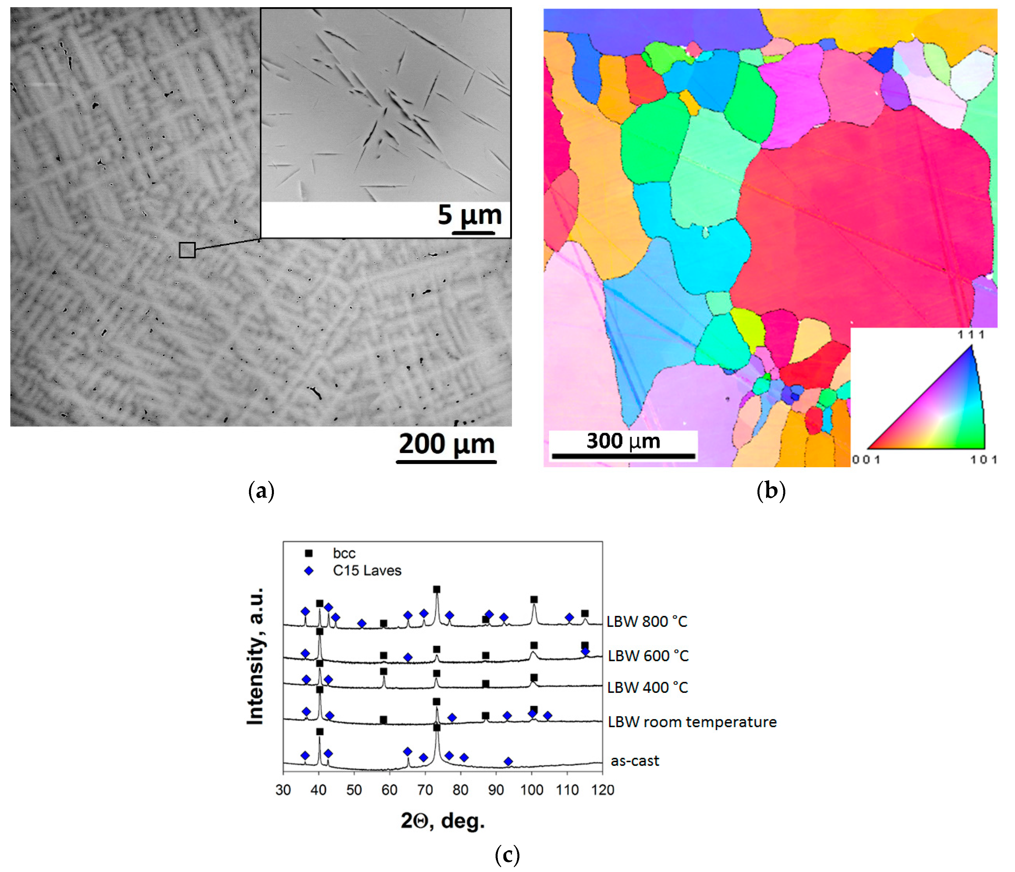
The initial, as-cast microstructure was quite heterogeneous and consisted of coarse bcc matrix grains with the lens-shaped Laves phase particles (
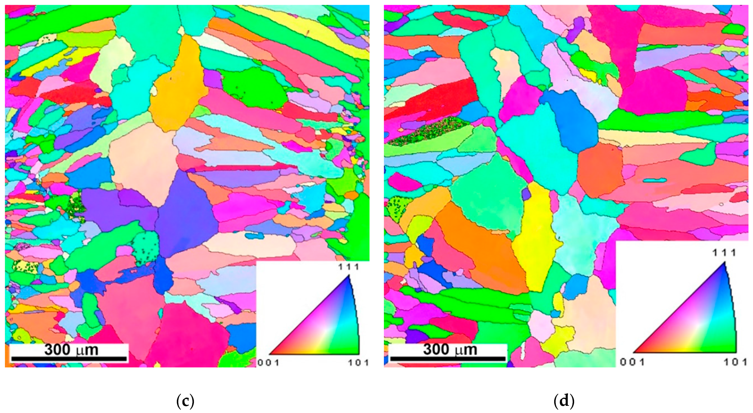
Figure 1). LBW has obviously affected the morphology of the bcc grains in the welding zone (WZ) (
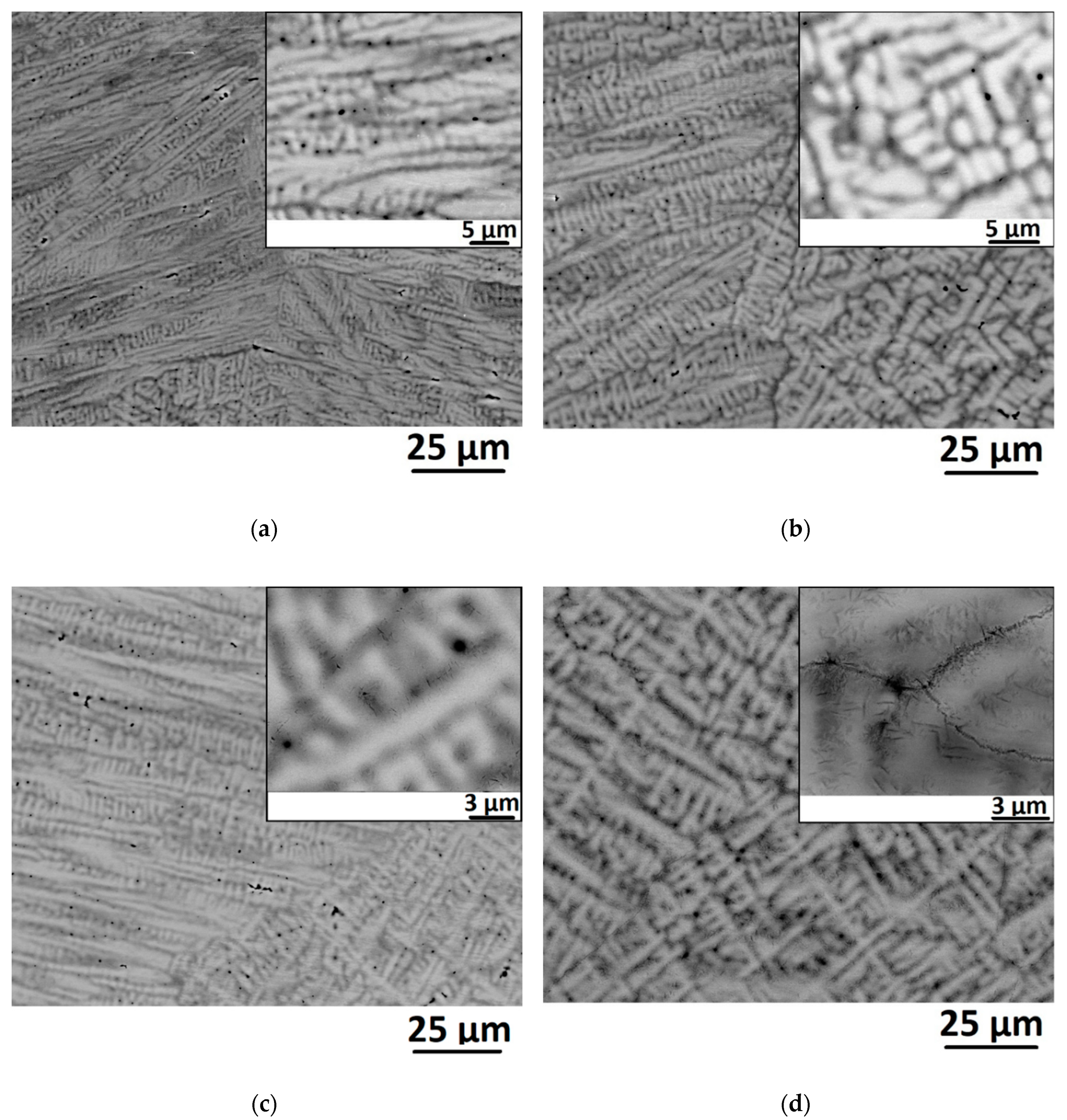
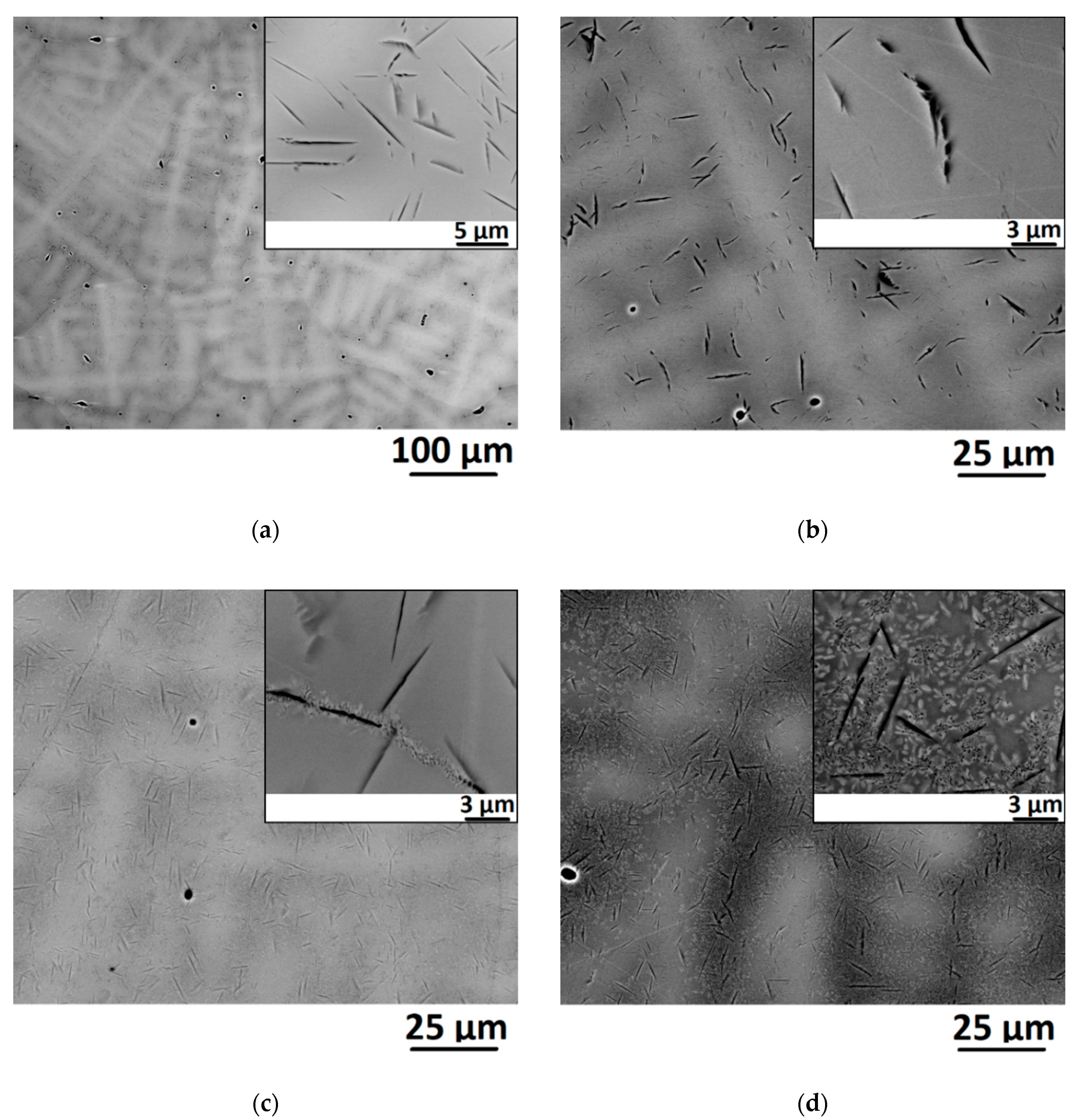
Figure 3). The grains became elongated in the direction normal to the laser beam, and the width of these grains increased with pre-heating temperature, most likely due to enhanced mobility of grain boundaries at higher pre-heating temperatures. In addition, LBW at the lower pre-heating temperatures (room temperature and 400 °C) has resulted in the Laves phase particles disappearance (
Figure 5a,b). The formation of these particles in the alloy deserves a more detailed analysis. The equilibrium phase diagram for the alloy constructed by the Thermo-Calc software is presented in
Figure 11.
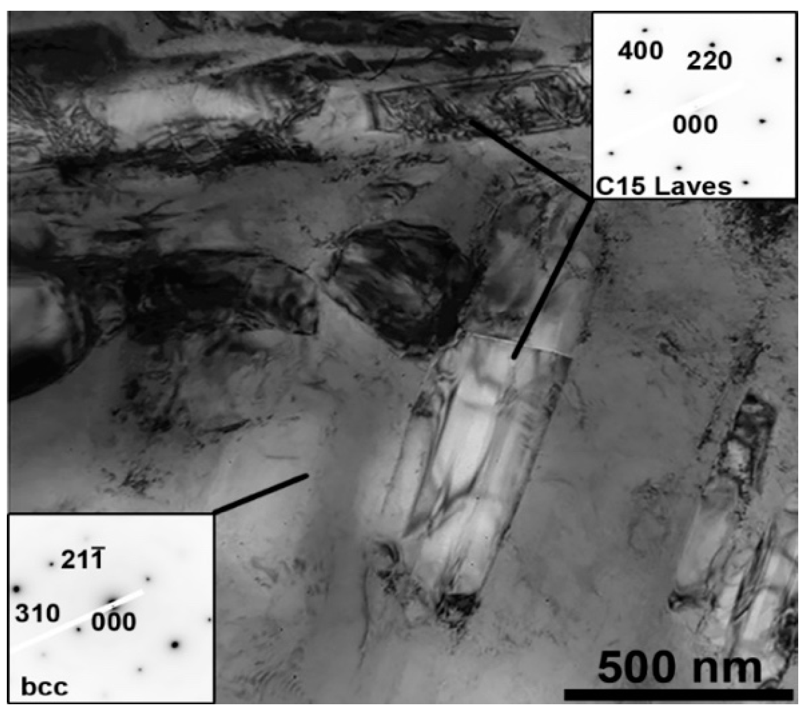
The alloy is supposed to have a single bcc phase structure starting from the solidus temperature of ~1500 °C till ~1000 °C; the latter corresponds to the onset of the Cr-rich C15 Laves phase precipitation. The fraction of the Laves phase increased with a decrease in temperature. Finally, at T ≈ 500 °C a Ti-rich hcp phase precipitated. The presence of the Laves phase in the initial as-cast condition can be most probably associated with a rather low cooling rate of relatively big ingots of the alloy that was not enough to “freeze” the high-temperature single-phase structure. In turn, faster cooling rates of the alloy, during the welded material solidification, prevented the formation of the Laves particles in the case of LBW at room temperature or 400 °C. During welding at higher pre-heating temperatures, the cooling rate is slower thereby allowing the Laves particles precipitation.
Also, annealing at 800 °C resulted in the precipitation of “additional” Laves particles in the base material after welding at pre-heating temperature of 600 °C or 800 °C. The formation of the particles can be attributed to the decomposition of the supersaturated bcc solid solution during holding at elevated temperatures (
Figure 11). Note that the particles precipitated in the inter-dendritic areas were observed mainly nearby the coarser particles, inherited from the as-cast condition. The Laves phase in this alloy is supposed to be composed of Cr and Nb predominantly [
33] and, therefore, the “additional” particles formed in the inter-dendritic areas which were rich in these elements (
Table 1), similarly to the Laves phase particles formation in the NbCrMo
0.5Ta
0.5TiZr alloy [
43].
Mechanical properties of the Ti
1.89NbCrV
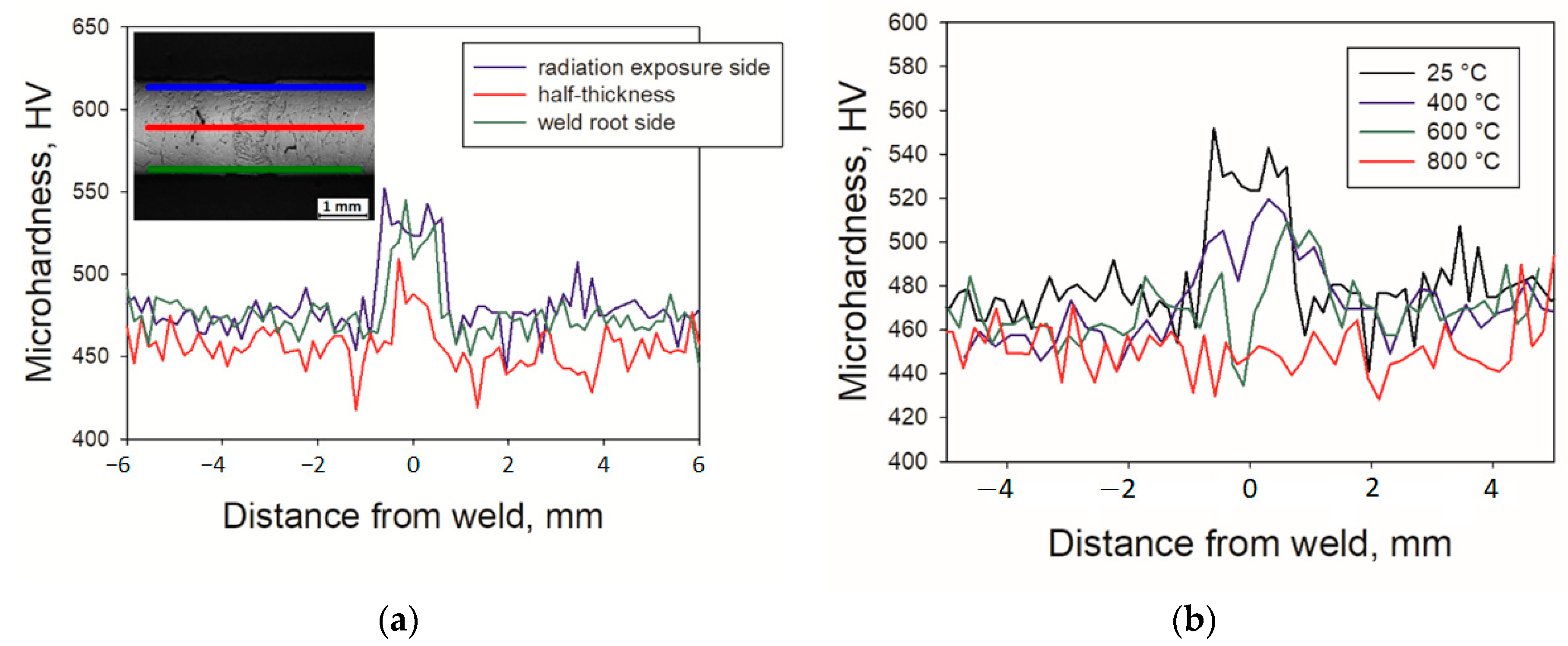
0.56 alloy were found to be strongly sensitive to the welding conditions. A noticeable increase in the fusion zone hardness, as well as the variation in the hardness with the temperature during welding (
Figure 8b), can be attributed to the bcc matrix grain size as a function of pre-heating temperature (
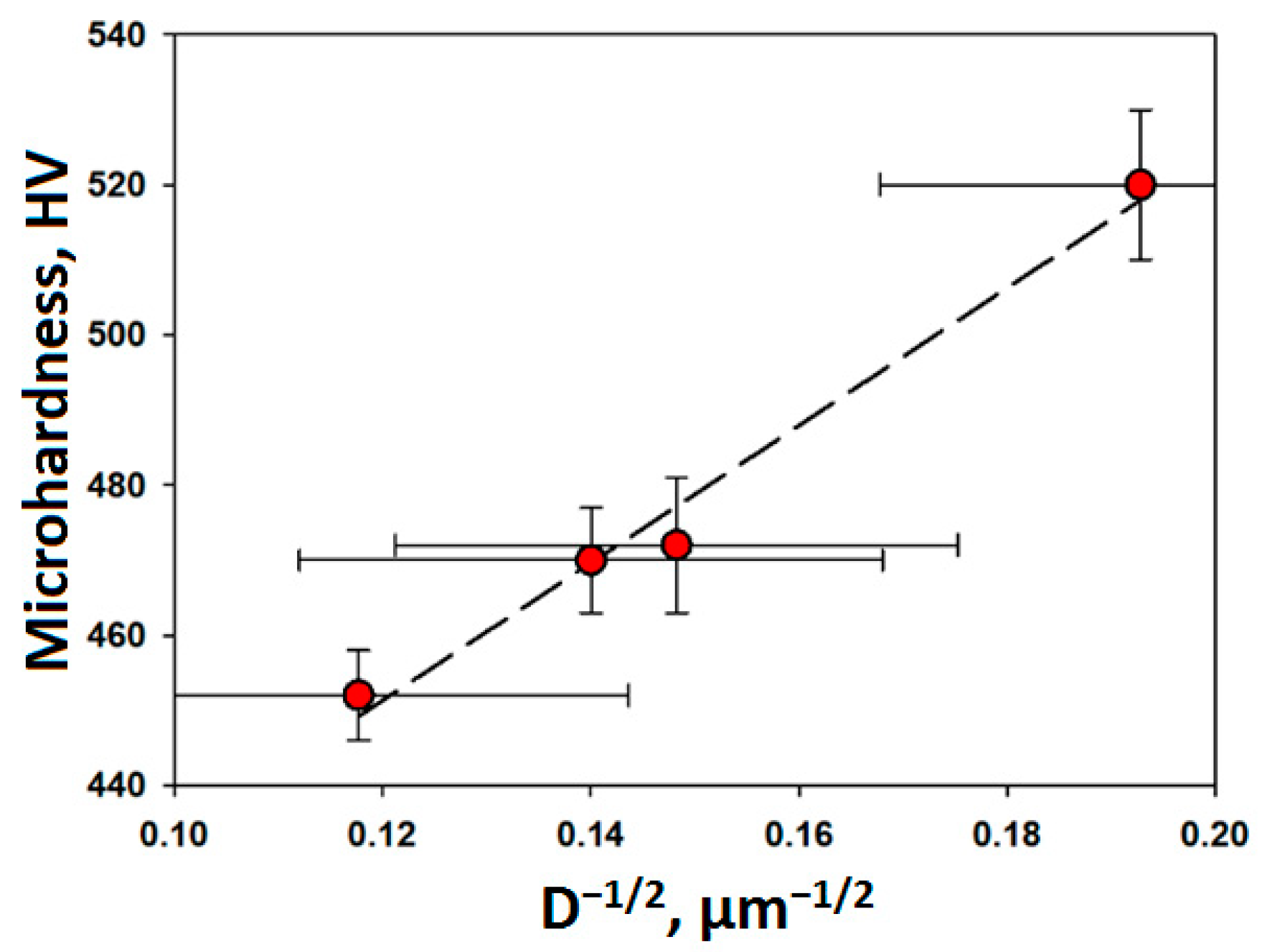
Figure 4). The relationship between the average hardness and average grain size in the fusion zone shown in
Figure 12 suggests that the Hall-Petch mechanism is active.
Due to the higher hardness of the weld, welded specimens fractured in the base material section during tensile tests. This type of behavior was observed earlier in other welded HEAs [
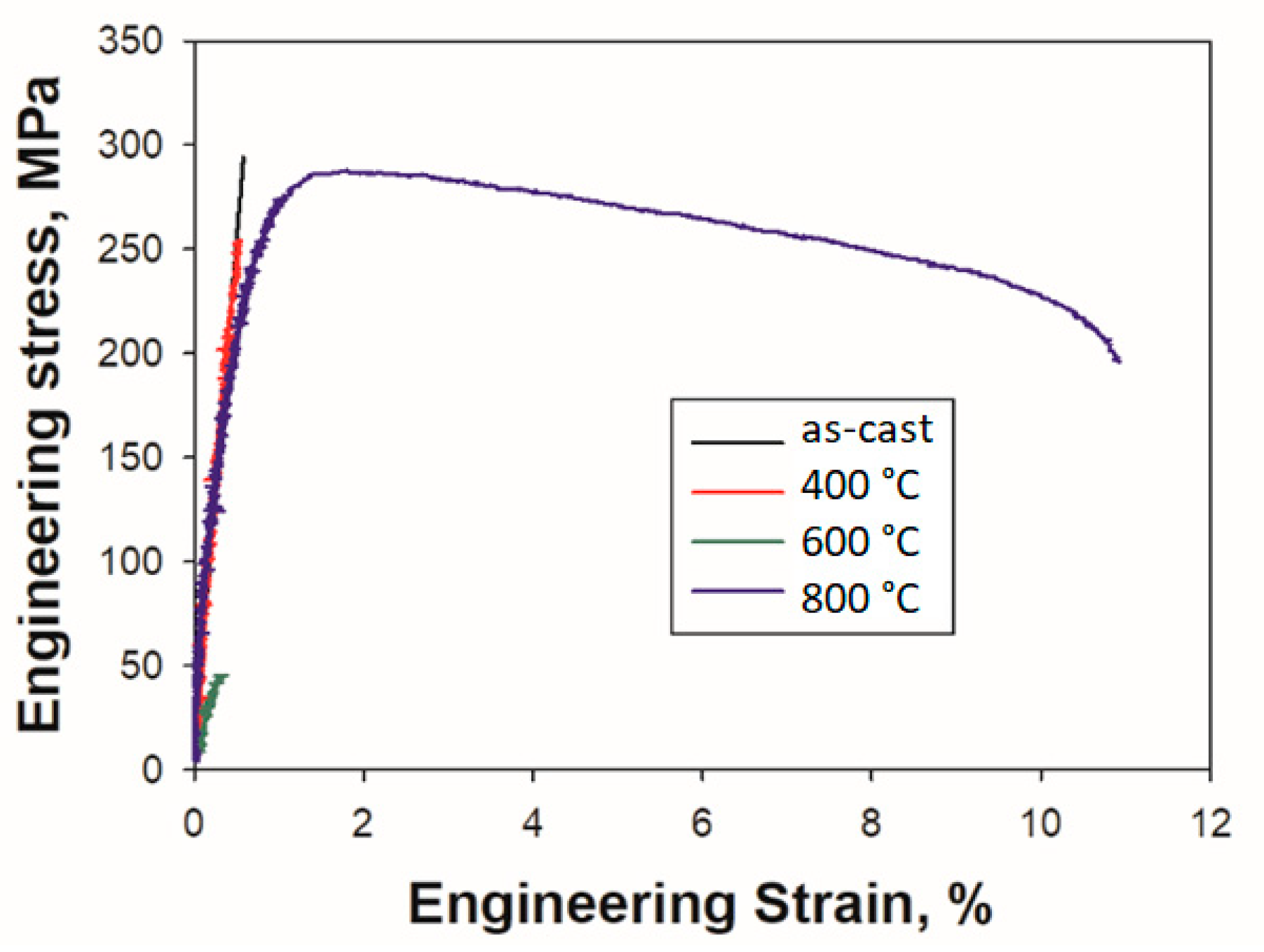
44]. However, the welding conditions strongly influenced on tensile behavior; for example, specimens welded at T ≤ 600 °C exhibited brittle fracture even at 750 °C while the alloy welded at 800 °C showed reasonable ductility (
Figure 9,
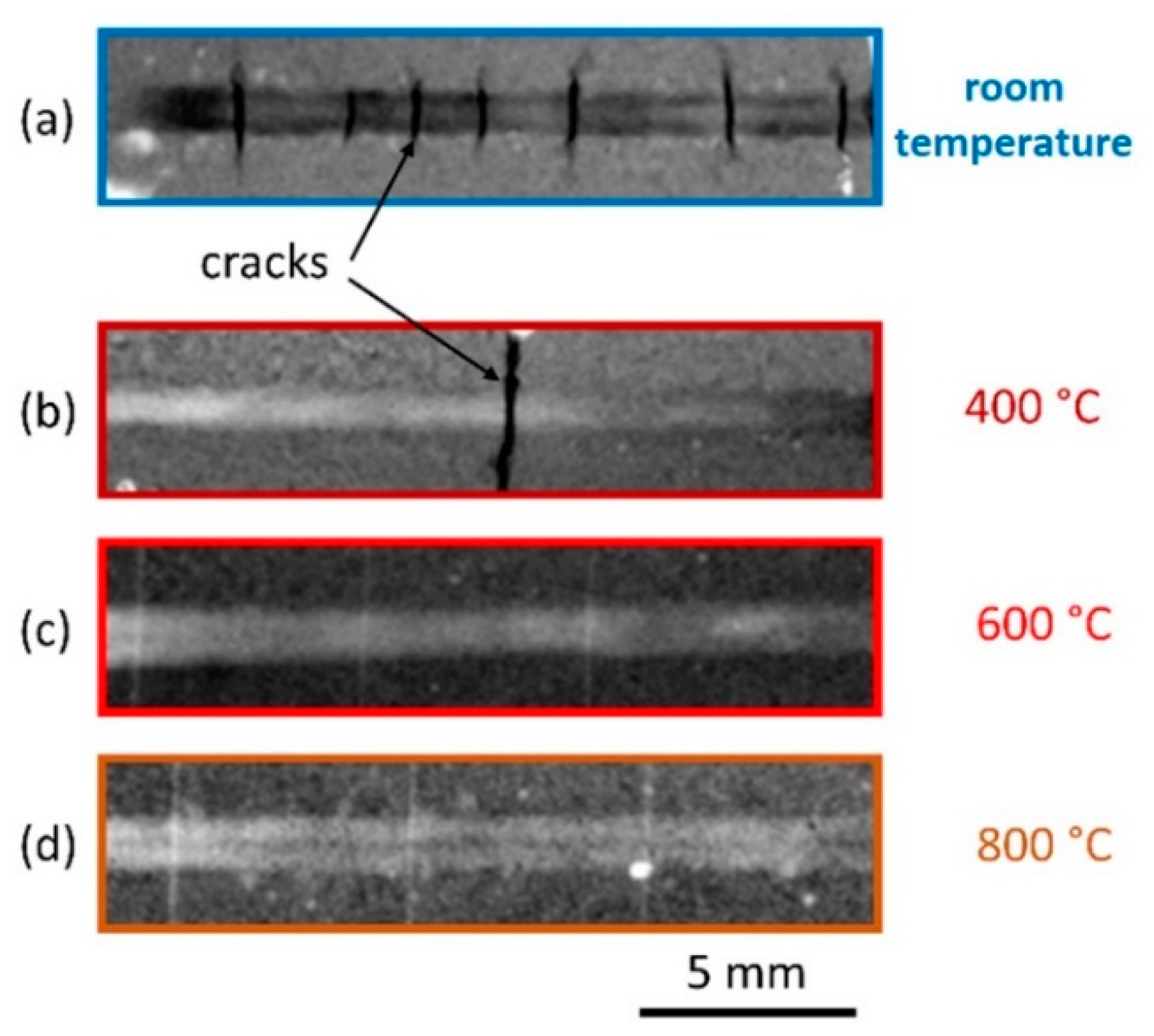
Table 2). One of the reasons for the increased ductility can be associated with the formation of a less defect structure (in terms of cracks) with an increase in the pre-heating temperature before welding (
Figure 2).
The “additional” Laves particles precipitation after welding at 800 °C can also provoke an increase in ductility. It is generally believed that the second phase particles precipitation should result in strengthening. However, in the present case nano-hardness of the particles-containing areas (480 HV) was found to be lower than that of the particle-free zone (560 HV) after welding at 800 °C. This result can most likely be related to (i) lower solid solution hardening of the bcc matrix due to depletion in Cr and Nb [
11,
33] and (ii) low (er) hardness of the Laves phase itself [
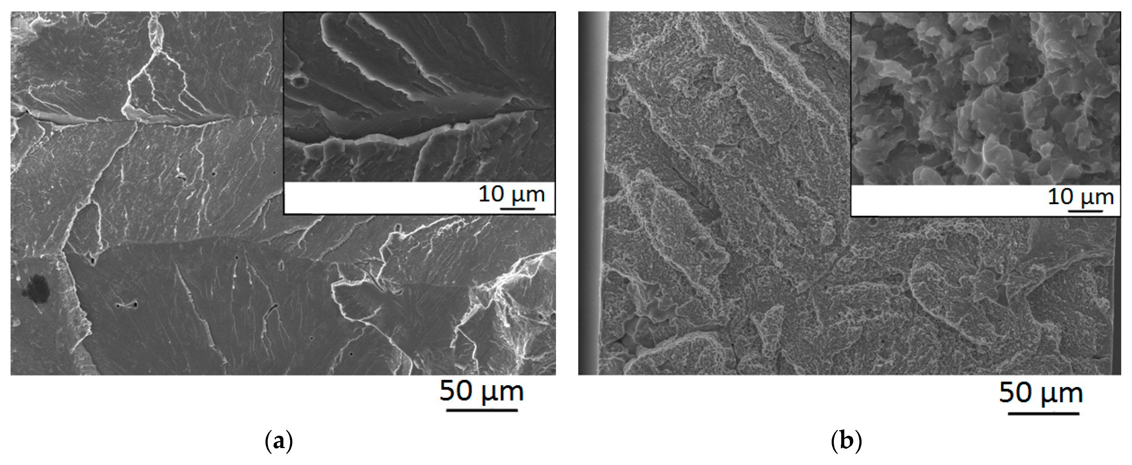
33]. That is why the Laves phase particles precipitation in the present alloy resulted in both some softening and an increase in ductility after welding at 800 °C. It should be also noted, that the size of the facets in
Figure 10b is correlated with the size of precipitation-free areas (
Figure 5d) thereby suggesting that the more ductile behavior can be associated with a temporary crack arrest in these Cr and Nb depleted regions.
The obtained results demonstrate for the first time the possibility to produce sound butt joints of the Ti
1.89NbCrV
0.56 RHEA by LBW, which is an important step toward potential practical applications of this new class of metallic alloys. However, the present study also emphasized the importance of LBW process parameters (particularly pre-heating temperature) to obtain good results, which is quite different from the transition metals HEAs [
27,
28,
29,
30,
31,
32,
44,
45]. Given the wide range of the available RHEAs compositions [
7], specific attention should be paid to select proper welding conditions for each individual alloy.
Author Contributions
Conceptualization, S.Z., N.S., N.K.; methodology, N.K., G.S., V.V.; validation, E.P., N.K.; formal analysis, N.K., N.S.; investigation, E.P., N.Y., V.V., R.D.; resources, G.S., N.K.; data curation, E.P.; writing—original draft preparation, N.S.; writing—review and editing, S.Z., N.K.; visualization, E.P., N.Y.; supervision, N.K., G.S.; project administration, S.Z.; funding acquisition, G.S.
Funding
This research was funded by the Russian Science Foundation Grant no. 19-79-30066.
Acknowledgments
The authors are grateful to the personnel of the Joint Research Center, Technology and Materials, Belgorod National Research University, for their assistance with the instrumental analysis.
Conflicts of Interest
The authors declare no conflict of interest.
References
- Perepezko, J.H. Materials science. The hotter the engine, the better. Science 2009, 326, 1068–1069. [Google Scholar] [CrossRef] [PubMed]
- Yeh, J.W.; Chen, S.K.; Lin, S.J.; Gan, J.Y.; Chin, T.S.; Shun, T.T.; Tsau, C.H.; Chang, S.Y. Nanostructured high-entropy alloys with multiple principal elements: Novel alloy design concepts and outcomes. Adv. Eng. Mater. 2004, 6, 299–303. [Google Scholar] [CrossRef]
- Miracle, D.B.; Senkov, O.N. A critical review of high entropy alloys and related concepts. Acta Mater. 2017, 122, 448–511. [Google Scholar] [CrossRef] [Green Version]
- Gorsse, S.; Miracle, D.B.; Senkov, O.N. Mapping the world of complex concentrated alloys. Acta Mater. 2017, 135, 177–187. [Google Scholar] [CrossRef] [Green Version]
- Gludovatz, B.; Hohenwarter, A.; Catoor, D.; Chang, E.H.; George, E.P.; Ritchie, R.O. A fracture-resistant high-entropy alloy for cryogenic applications. Science 2014, 345, 1153–1158. [Google Scholar] [CrossRef] [Green Version]
- Li, Z.; Pradeep, K.G.; Deng, Y.; Raabe, D.; Tasan, C.C. Metastable high-entropy dual-phase alloys overcome the strength-ductility trade-off. Nature 2016, 534, 227–230. [Google Scholar] [CrossRef]
- Senkov, O.N.; Miracle, D.B.; Chaput, K.J.; Couzinie, J.-P. Development and exploration of refractory high entropy alloys—A review. J. Mater. Res. 2018, 33, 3092–3128. [Google Scholar] [CrossRef] [Green Version]
- Senkov, O.N.; Wilks, G.B.; Miracle, D.B.; Chuang, C.P.; Liaw, P.K. Refractory high-entropy alloys. Intermetallics 2010, 18, 1758–1765. [Google Scholar] [CrossRef]
- Senkov, O.N.; Wilks, G.B.; Scott, J.M.; Miracle, D.B. Mechanical properties of Nb25Mo25Ta25W25 and V20Nb20Mo20Ta20W20 refractory high entropy alloys. Intermetallics 2011, 19, 698–706. [Google Scholar] [CrossRef]
- Senkov, O.N.; Senkova, S.V.; Woodward, C.; Miracle, D.B. Low-density, refractory multi-principal element alloys of the Cr-Nb-Ti-V-Zr system: Microstructure and phase analysis. Acta Mater. 2013, 61, 1545–1557. [Google Scholar] [CrossRef]
- Senkov, O.N.; Senkova, S.V.; Miracle, D.B.; Woodward, C. Mechanical properties of low-density, refractory multi-principal element alloys of the Cr-Nb-Ti-V-Zr system. Mater. Sci. Eng. A 2013, 565, 51–62. [Google Scholar] [CrossRef]
- Senkov, O.N.; Senkova, S.V.; Woodward, C.F. Effect of aluminum on the microstructure and properties of two refractory high-entropy alloys. Acta Mater. 2014, 68, 214–228. [Google Scholar] [CrossRef]
- Senkov, O.N.; Woodward, C.; Miracle, D.B. Microstructure and properties of aluminum-containing refractory high-entropy alloys. JOM 2014, 66, 2030–2042. [Google Scholar] [CrossRef]
- Stepanov, N.D.; Shaysultanov, D.G.; Salishchev, G.A.; Tikhonovsky, M.A. Structure and mechanical properties of a light-weight AlNbTiV high entropy alloy. Mater. Lett. 2015, 142, 153–155. [Google Scholar] [CrossRef]
- Stepanov, N.D.; Yurchenko, N.Y.; Skibin, D.V.; Tikhonovsky, M.A.; Salishchev, G.A. Structure and mechanical properties of the AlCrxNbTiV (x = 0, 0.5, 1, 1.5) high entropy alloys. J. Alloys Compd. 2015, 652, 266–280. [Google Scholar] [CrossRef]
- Stepanov, N.D.; Yurchenko, N.Y.; Panina, E.S.; Tikhonovsky, M.A.; Zherebtsov, S.V. Precipitation-strengthened refractory Al0.5CrNbTi2V0.5 high entropy alloy. Mater. Lett. 2017, 188, 162–164. [Google Scholar] [CrossRef]
- Yurchenko, N.Y.; Stepanov, N.D.; Zherebtsov, S.V.; Tikhonovsky, M.A.; Salishchev, G.A. Structure and mechanical properties of B2 ordered refractory AlNbTiVZrx (x = 0–1.5) high-entropy alloys. Mater. Sci. Eng. A 2017, 704, 82–90. [Google Scholar] [CrossRef] [Green Version]
- Senkov, O.N.; Jensen, J.K.; Pilchak, A.L.; Miracle, D.B.; Fraser, H.L. Compositional variation effects on the microstructure and properties of a refractory high-entropy superalloy AlMo0.5NbTa0.5TiZr. Mater. Des. 2018, 139, 498–511. [Google Scholar] [CrossRef]
- Senkov, O.N.; Rao, S.; Chaput, K.J.; Woodward, C. Compositional effect on microstructure and properties of NbTiZr-based complex concentrated alloys. Acta Mater. 2018, 151, 201–215. [Google Scholar] [CrossRef]
- Chen, H.; Kauffmann, A.; Gorr, B.; Schliephake, D.; Seemüller, C.; Wagner, J.N.; Christ, H.-J.; Heilmaier, M. Microstructure and mechanical properties at elevated temperatures of a new Al-containing refractory high-entropy alloy Nb-Mo-Cr-Ti-Al. J. Alloys Compd. 2016, 661, 206–215. [Google Scholar] [CrossRef] [Green Version]
- Xu, Z.Q.; Cheng, X.W.; Wang, M.; Chen, Y.W.; Tan, Y.D.; Ma, Z.L. Design of novel low-density refractory high entropy alloys for high temperature applications. Mater. Sci. Eng. A 2019, 755, 318–322. [Google Scholar] [CrossRef]
- Miracle, D.; Majumdar, B.; Wertz, K.; Gorsse, S. New strategies and tests to accelerate discovery and development of multi-principal element structural alloys. Scr. Mater. 2017, 127, 195–200. [Google Scholar] [CrossRef]
- Senkov, O.N.; Semiatin, S.L. Microstructure and properties of a refractory high-entropy alloy after cold working. J. Alloys Compd. 2015, 649, 1110–1123. [Google Scholar] [CrossRef]
- Senkov, O.N.; Pilchak, A.L.; Semiatin, S.L. Effect of cold deformation and annealing on the microstructure and tensile properties of a HfNbTaTiZr refractory high entropy alloy. Metall. Mater. Trans. A 2018, 49, 2876–2892. [Google Scholar] [CrossRef]
- Lilensten, L.; Couzinié, J.-P.; Bourgon, J.; Perrière, L.; Dirras, G.; Prima, F.; Guillot, I. Design and tensile properties of a bcc Ti-rich high-entropy alloy with transformation-induced plasticity. Mater. Res. Lett. 2017, 5, 110–116. [Google Scholar] [CrossRef] [Green Version]
- Sheikh, S.; Shafeie, S.; Hu, Q.; Ahlström, J.; Persson, C.; Veselý, J.; Zýka, J.; Klement, U.; Guo, S. Alloy design for intrinsically ductile refractory high-entropy alloys. J. Appl. Phys. 2016, 120, 164902. [Google Scholar] [CrossRef] [Green Version]
- Wu, Z.; David, S.A.; Feng, Z.; Bei, H. Weldability of a high entropy CrMnFeCoNi alloy. Scr. Mater. 2016, 124, 81–85. [Google Scholar] [CrossRef] [Green Version]
- Wu, Z.; David, S.A.; Leonard, D.N.; Feng, Z.; Bei, H. Microstructures and mechanical properties of a welded CoCrFeMnNi high-entropy alloy. Sci. Technol. Weld. Join. 2018, 23, 585–595. [Google Scholar] [CrossRef]
- Zhu, Z.G.; Sun, Y.F.; Ng, F.L.; Goh, M.H.; Liaw, P.K.; Fujii, H.; Nguyen, Q.B.; Xu, Y.; Shek, C.H.; Nai, S.M.L.; et al. Friction-stir welding of a ductile high entropy alloy: Microstructural evolution and weld strength. Mater. Sci. Eng. A 2018, 711, 524–532. [Google Scholar] [CrossRef]
- Zhu, Z.G.; Sun, Y.F.; Goh, M.H.; Ng, F.L.; Nguyen, Q.B.; Fujii, H.; Nai, S.M.L.; Wei, J.; Shek, C.H. Friction stir welding of a CoCrFeNiAl0.3 high entropy alloy. Mater. Lett. 2017, 205, 142–144. [Google Scholar] [CrossRef]
- Kashaev, N.; Ventzke, V.; Stepanov, N.; Shaysultanov, D.; Sanin, V.; Zherebtsov, S. Laser beam welding of a CoCrFeNiMn-type high entropy alloy produced by self-propagating high-temperature synthesis. Intermetallics 2018, 96, 63–71. [Google Scholar] [CrossRef]
- Shaysultanov, D.; Stepanov, N.; Malopheyev, S.; Vysotskiy, I.; Sanin, V.; Mironov, S.; Kaibyshev, R.; Salishchev, G.; Zherebtsov, S. Friction stir welding of a carbon-doped CoCrFeNiMn high-entropy alloy. Mater. Charact. 2018, 145, 353–361. [Google Scholar] [CrossRef] [Green Version]
- Yurchenko, N.Y.; Panina, E.S.; Zherebtsov, S.V.; Tikhonovsky, M.A.; Salishchev, G.A.; Stepanov, N.D. Microstructure evolution of a novel low-density Ti-Cr-Nb-V refractory high entropy alloy during cold rolling and subsequent annealing. Mater. Charact. 2019, 158, 109980. [Google Scholar] [CrossRef]
- Auwal, S.T.; Ramesh, S.; Yusof, F.; Manladan, S.M. A review on laser beam welding of titanium alloys. Int. J. Adv. Manuf. Technol. 2018, 97, 1071–1098. [Google Scholar] [CrossRef]
- Akman, E.; Demir, A.; Canel, T.; Sınmazçelik, T. Laser welding of Ti6Al4V titanium alloys. J. Mater. Process. Technol. 2009, 209, 3705–3713. [Google Scholar] [CrossRef]
- Li, Z.; Gobbi, S.L.; Norris, I.; Zolotovsky, S.; Richter, K.H. Laser welding techniques for titanium alloy sheet. J. Mater. Process. Technol. 1997, 65, 203–208. [Google Scholar] [CrossRef]
- Liu, J.; Dahmen, M.; Ventzke, V.; Kashaev, N.; Poprawe, R. The effect of heat treatment on crack control and grain refinement in laser beam welded β-solidifying TiAl-based alloy. Intermetallics 2013, 40, 65–70. [Google Scholar] [CrossRef]
- Kashaev, N.; Ventzke, V.; Fomichev, V.; Fomin, F.; Riekehr, S. Effect of Nd:YAG laser beam welding on weld morphology and mechanical properties of Ti-6Al-4V butt joints and T-joints. Opt. Lasers Eng. 2016, 86, 172–180. [Google Scholar] [CrossRef]
- Burkhardt, I.; Ventzke, V.; Riekehr, S.; Kashaev, N.; Enz, J. Laser welding and microstructural characterization of dissimilar γ-TiAl-Ti6242 joints. Intermetallics 2019, 104, 74–83. [Google Scholar] [CrossRef]
- Oliver, W.C.; Pharr, G.M. Measurement of hardness and elastic modulus by instrumented indentation: Advances in understanding and refinements to methodology. J. Mater. Res. 2004, 19, 3–20. [Google Scholar] [CrossRef]
- Senkov, O.N.; Zhang, C.; Pilchak, A.L.; Payton, E.J.; Woodward, C.; Zhang, F. CALPHAD-aided development of quaternary multi-principal element refractory alloys based on NbTiZr. J. Alloys Compd. 2019, 783, 729–742. [Google Scholar] [CrossRef]
- Cahn, R.W.; Haasen, P. Physical Metallurgy; North-Holland Physics Pub.: Amsterdam, The Netherlands, 1983; ISBN 0444867872. [Google Scholar]
- Senkov, O.N.; Woodward, C.F. Microstructure and properties of a refractory NbCrMo0.5Ta0.5TiZr alloy. Mater. Sci. Eng. A 2011, 529, 311–320. [Google Scholar] [CrossRef]
- Kashaev, N.; Ventzke, V.; Petrov, N.; Horstmann, M.; Zherebtsov, S.; Shaysultanov, D.; Sanin, V.; Stepanov, N. Fatigue behaviour of a laser beam welded CoCrFeNiMn-type high entropy alloy. Mater. Sci. Eng. A 2019, 766, 138358. [Google Scholar] [CrossRef]
- Martin, A.C.; Fink, C. Initial weldability study on Al0.5CrCoCu0.1FeNi high-entropy alloy. Weld. World 2019, 63, 739–750. [Google Scholar] [CrossRef]
Figure 1.
Structure of the Ti1.89CrNbV0.56 alloy in the initial as-cast condition: (a) SEM-BSE image; (b) crystal orientation map; (c) XRD pattern.
Figure 2.
Radiographs of butt joints welded at room temperature (a) or at different pre-heating temperatures; (b) 400 °C; (c) 600 °C, and (d) 800 °C.
Figure 3.
Crystal orientation maps of butt joint cross-section (seams are vertical in all cases) obtained by laser beam welding (LBW) with different pre-heating temperatures: (a) Room temperature; (b) 400 °C; (c) 600 °C; (d) 800 °C.
Figure 4.
Dependence of the transversal size of the columnar grains inside the welds on the pre-heating temperature.
Figure 5.
SEM-BSE images of the welding zone after LBW at different pre-heating temperatures: (a) room temperature; (b) 400 °C; (c) 600 °C; (d) 800 °C.
Figure 6.
SEM-BSE images of the base material in specimens subjected to LBW at different pre-heating temperatures: (a) room temperature; (b) 400 °C; (c) 600 °C; (d) 800 °C.
Figure 7.
TEM bright-field image of the base material in the specimen after LBW at the pre-heating temperature of 800 °C.
Figure 8.
Microhardness profiles across the weld: (a) at room temperature along radiation exposure side (blue line), half-thickness (red line) and weld root side (green line); (b) at different pre-heating temperature before welding along the half-thickness line.
Figure 9.
Engineering stress-strain curves of the Ti1.89NbCrV0.56 alloy tensioned at 750 °C in the as-cast state and after LBW at 400, 600 or 800 °C.
Figure 10.
Fracture surfaces of the tensile specimens after LBW at different pre-heating temperatures: (a) 400 °C; (b) 800 °C.
Figure 11.
Phase diagram of the Ti1.89NbCrV0.56 alloy constructed using the Thermo-Calc software (BCC—body-centered cubic structure; HCP—hexagonal close packed structure).
Figure 12.
Relationship between the hardness and grain size in the fusion zone.
Table 1.
Chemical composition of the structural constituents of the Ti1.89CrNbV0.56 alloy, in at. %.
| Structural Constituent | Ti | Cr | Nb | V |
|---|
| Interdendrite | 39.8 | 24.7 | 24.2 | 11.3 |
| Alloy | 43.7 | 22.1 | 22.3 | 11.9 |
Table 2.
Mechanical properties (YS—yield strength, UTS—ultimate tensile strength, FS—fracture stress, δ—elongation to fracture) of the Ti1.89NbCrV0.56 alloy obtained by tensile tests at 750 °C in the as-cast state and after LBW at 400, 600 or 800 °C.
| Condition | YS, Mpa | UTS (or FS), Mpa | δ, % |
|---|
| As-cast | - | (250) | 0 |
| LBW 400 °C | - | (255) | 0 |
| LBW 600 °C | - | (45) | 0 |
| LBW 800 °C | 265 | 285 | 10.4 |
© 2019 by the authors. Licensee MDPI, Basel, Switzerland. This article is an open access article distributed under the terms and conditions of the Creative Commons Attribution (CC BY) license (http://creativecommons.org/licenses/by/4.0/).

 ,
, 


