1. Introduction
Steel corrosion caused by chloride ion attack is one of the main causes of the structural deterioration of reinforced concrete structures. Numerous methods have been proposed to protect steel bars in RC structures from corrosion, such as corrosion inhibitor coatings [
1,
2,
3], corrosion inhibitor mixtures [
4], and cathodic protection [
5]. However, the cost of the repair and rehabilitation of RC structures that suffer from corrosion constitutes a large portion of infrastructure expenditure in many countries, which can be attributed to the limited knowledge regarding the durability deterioration of the in-field RC structure [
6]. Therefore, to make these methods for controlling the corrosion of the RC structure as effectively as desired, it is necessary to find the law of corrosion-induced structural deterioration and to develop accurate prediction.
The process of corrosion-induced structural deterioration can be divided into four stages, namely: de-passivation, cracking, spalling, and collapse [
7]. Cracking occurs when the tensile stresses caused by the expansion of corrosion products reached the tensile strength of the concrete. When coming down to the negative effects of cracking, the most significant is the acceleration of steel corrosion due to the more rapid ingress of an aggressive medium through crack paths. Therefore, surface cracking is always treated as a sign of the durability limit state [
8]. Currently, a large number of empirical, analytical, and numerical models have been proposed by domestic scholars for predicting corrosion-induced concrete cracking. However, the effect of external loads is not considered in most of the models [
9]. In fact, most reinforced concrete structures in corrosive environments are always subjected to external loads at the same time, which not only have a significant influence on the field distribution within the structure, but also alter the pore structure. As a result, the ingress of an aggressive medium [
10] and the filling behavior of corrosion products are affected [
11]. Therefore, accurately predicting the characteristics of corrosion-induced cracking in loaded reinforced concrete structures enables the deterioration mechanism of concrete structures to be explicit, and provides the necessary theoretical support for the service life assessment of reinforced concrete structures.
The studies on the corrosion-induced cracking of loaded reinforced concrete are mainly based on experimental methods. Yu studied the surface cracking pattern of beams, the midspan of which is subjected to concentrated forces in a salt spray environment [
12]. The corrosion-induced cracks that were initially formed were found to always be connected to the load-induced cracks. Fu observed the surface cracking pattern of pre-loaded concrete beams that had been subjected wet and dry cycles for four years [
13]. The space of corrosion-induced cracks was narrower under the impact of external loads. Shi compared the internal cracking pattern of concrete prisms subjected to two months of coupled load and accelerated corrosion, and found that internal cracks in the concrete tended to develop along the defects caused by loading [
14]. Shen found that cyclic loading affected the sectional non-uniform corrosion layer distribution, thereby controlling the location of the initial corrosion-induced crack [
15]. The above experimental studies suggest that external loads affect the number and orientation of corrosion-induced cracks, and the corresponding mechanism may be closely related to the load-induced damage in concrete.
A few analytical models and numerical models considered the effect of external loads. Based on a complex analysis, Lin predicted corrosion-induced concrete cracking under a triaxial stress state. [
16]. On the basis of the thick-walled cylinder model, Wang considered the effect of radial stresses sourced from the deformation at the interface between the concrete and steel ribs [
17]. Jin established a numerical model based on the improved CDM-XFEM method, and the effects of load-induced cracks on the corrosion-induced cracking pattern were investigated [
18]. All of the aforementioned models promoted the development of the study on the corrosion-induced cracking of the loaded concrete members, but the other non-negligible factors were not taken into consideration, including the transport of corrosion products and non-uniform corrosion.
In addition to the lack of models, the viewpoints about the loading impacts on corrosion-induced concrete cracking were not consistent in different studies. Malumbela observed the variation of the surface crack widths of beams subjected to 1%, 8%, and 12% ultimate loads under accelerated corrosion conditions and found that the rate of crack propagation was independent of the load level [
19]. In contrast, Zhang observed the surface crack widths of two beams subjected to the coupled load-chloride condition for 14 and 23 years of age, respectively, and found that the surface crack widths on the tension face were much larger than those on the compression face, showing the high correlation between load and corrosion-induced cracking [
20]. Xu concluded that the effect of external loads on corrosion-induced cracking was two-fold, load-induced damages weakened concrete’s resistance to corrosion-induced expansion, while load-induced defects and microcracks at the steel–concrete interface also provided voids for corrosion product filling, thus retarding the corrosion-induced crack growth [
21]. In conclusion, the characteristics of corrosion-induced concrete cracking under external loads remained unclear.
In this study, the process of corrosion-induced cracking was elaborated on at multiple scales. Based on the transport of corrosion products in the pore structure and the crack gaps of concrete, a numerical model for predicting corrosion-induced concrete was proposed. The cracking patterns obtained from the model were in fair agreement with the experimental data. Then, several concrete beams with different loading conditions were set up, and the steel corrosion-cracking pattern relation at the surface cracking moment and the durability limit state were investigated. The influence of external loads on the corrosion-induced crack widths of concrete beams was quantified and the related mechanism was discussed in depth.
2. Framework of Proposed Numerical Model
As mentioned earlier, external loads have significant effects on corrosion-induced concrete cracking and have been considered in a few models [
16,
17,
18]. However, the transport of corrosion products and non-uniform corrosion have not been considered. The reason for this is that taking external loads into account requires a complete model of the RC component at a macroscopic scale, whereas the distribution of corrosion products is related to physical-chemical process at a microscopic scale. The contradiction of the research scale leads to difficulties, for which the proposed model could solve by considering the external loads and microscopic behavior of corrosion products simultaneously.
Based on the DUCOM-COM3 software [
22] and previous work simulating the three-dimensional non-uniform corrosion [
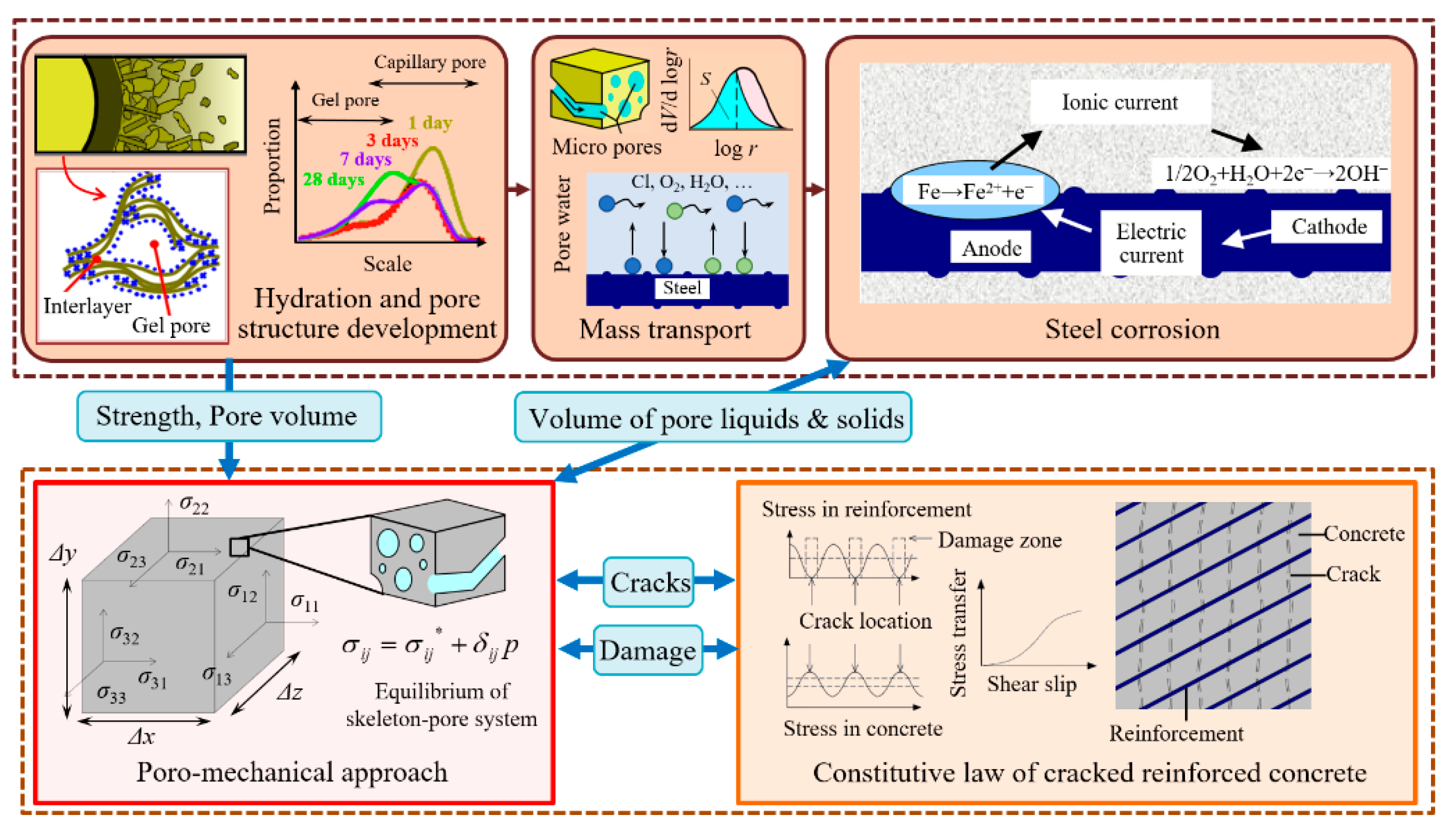
23], a modified numerical model is established for predicting the corrosion-induced cracking of RC components under external loads. In this model, a multi-scale corrosion-induced cracking process is considered, and the corresponding theoretical framework is shown in
Figure 1. At a microscopic scale, the aggressive mediums invade concrete and the zero-valence iron is oxidized to corrosion products in the form of Fe(II) and Fe(III) after a complex electrochemical process. Some of the corrosion products existing in the form of gel can transport the pores and cracks, and other crystallized corrosion products adhere to the steel surface. At a macroscopic scale, the concrete components are subjected to both corrosion-induced stress and external loads. Cracking occurs when the total stress exceeds the tensile strength of the concrete. Most importantly, concrete is regarded as a skeleton-pore system and can be divided into numerous elements. Based on poro-mechanics, the volumetric expansion of non-uniformly distributed corrosion products can be transformed into stress tensors for each concrete element, thus enabling the link between the microscopic scale and macroscopic scale. The details of the proposed numerical model are introduced in the following sections.
2.1. Formation and Transport of Corrosion Products
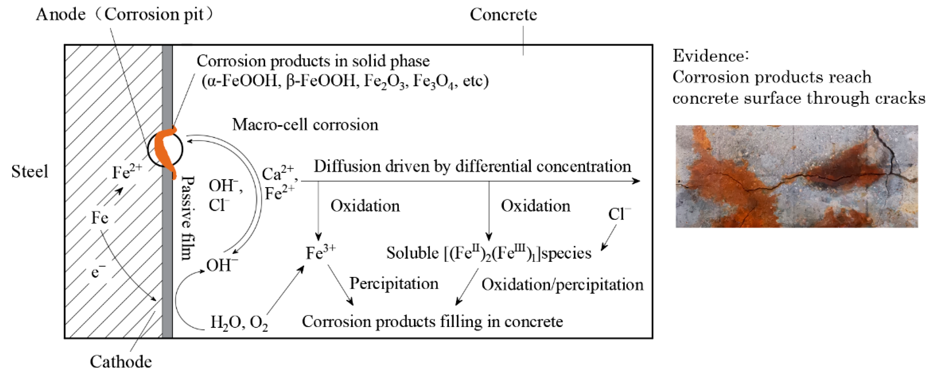
The formation of corrosion products is the beginning of the concrete cracking process. When the chloride ion concentration on the steel surface reaches the threshold, the passivation films are damaged and then the anodic reaction occurs, accompanied by the metal dissolution. The hydrolysis of dissolved Fe cations results in a reduction in pH in the local areas. Simultaneously, the electrons migrate from anodic to cathodic regions, with reduction reactions occurring in the cathodic area. At this point, the potential difference between the anodic and cathodic regions can reach hundreds of millivolts, resulting in macro-cell corrosion, which is contributed to by the migration of electrons and the diffusion of ions. The mobility, charge, and concentration of ions control the magnitude of the macro-current and the relevant chemical reactions together [
24]. The above process is shown in
Figure 2.
The constituents of corrosion products depend on specific chemical reactions, which are related to the internal environment and concrete composition. There are 16 known corrosion products, and seven common ones that are always found in reinforced concrete structures are listed in
Table 1 [
25]. Generally, α-FeOOH, γ-FeOOH, and α-Fe
2O
3 have a low solubility and are chemically stable, accumulating on the steel surface in a solid phase as the main components of the corrosion layer. β-FeOOH is mainly found in chlorine-rich environments and has a relatively high solubility. [Fe
IIx Fe
IIIy] species, often referred to as “green rust”, are a class of compounds containing both Fe(II) and Fe(III) complexes, the anions of which usually consist of OH
− and one of Cl
−, CO3
2−, and SO4
2− [
26]. The green rust” has a relatively high solubility up to 0.18 mol/L [
27] and is unstable. Thus, it can be easily oxidized to hydroxyl oxide iron.
Because of the different solubility of various corrosion products, both the solid and liquid phases (corrosion products gel) can coexist [
28]. The ratio of those two phases is found to be related to the corrosion rate
icorr, as shown in Equation (1) [
29].
where
β is the volumetric ratio of corrosion products in the solid phase, and 1 −
β is the volumetric ratio of corrosion products in the liquid phase.
As mentioned before, corrosion products in liquid phase can be transported from the steel surface to the surrounding pores and cracks in concrete. A widely accepted explanation about corrosion products’ transport mechanism is the dissolution–diffusion/electromigration mechanism of “green rust”, as shown in
Figure 2 [
11,
24]. Moreover, it is known that concrete is a porous material. Considering the perspective of pore mechanics, the corrosion products in liquid phase can be treated as a pore fluid, thus Darcy’s law is applicable to quantify their transport behavior. In the existing research, the permeability coefficient
k of the corrosion products in the pore structure of concrete is specified as approximately 5 × 10
−12 m/s and increases when concrete cracking occurs [
29]:
where <
i,
j,
k> is the direction of the coordinate axis in the orthogonal coordinate system,
j and
k are parallel to the crack plane,
ki is modified permeability coefficient in the
i direction (m/s), and
represents the strain of concrete perpendicular to the fracture plane.
2.2. Calculation of Corrosion-Induced Expansion
The formula of corrosion-induced expansion driven by corrosion products in the solid phase is widely accepted, as shown in Equation (2) and
Figure 2 [
30]:
where
is the stress tensor in the corroded steel bar,
Dijkl is the stiffness matrix of the corroded steel bar,
εkl is the strain tensor of corrosion products,
δkl is the Kronecker symbol,
εfree(
βγ) is the free expansion of corroded steel bar, and
a0 is the volumetric expansion rate of corrosion products in the solid phase.
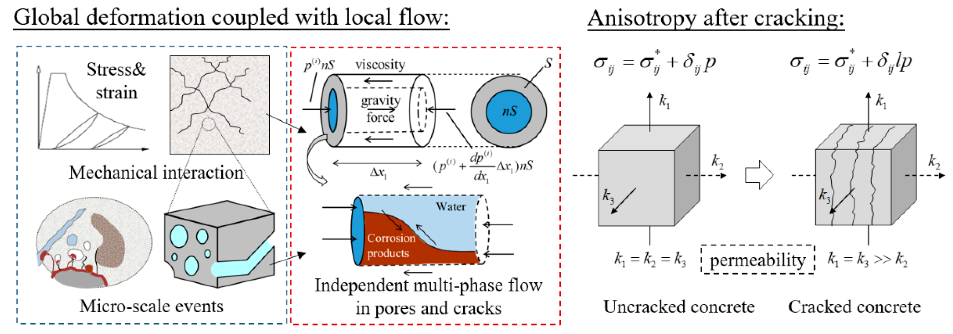
The calculation of corrosion-induced expansion promoted by corrosion products in the liquid phase is based on poro-mechanics. On the one hand, concrete is a porous material and the liquid phase corrosion products are in the cracks and pores, not attached to the surface of the steel bar. On the other hand, the liquid phase corrosion products interact with solid phase concrete skeletons as they are transported inside the pore structure. Therefore, the portion in the solid phase (aggregate and cement) within concrete is considered as the skeleton, and the corrosion products in the liquid phase are considered as the flowing pore substance, as shown in
Figure 3. The density
ρ of this skeleton-pore system can be expressed as follows:
where
ρc is the density of skeleton (kg/m
3),
ρl is the density of pore substance (kg/m
3), and
n is the pore ratio of the skeleton-pore system.
When concrete is not cracked, the pore pressure can be considered isotropic. When the concrete is cracked, the pore pressure is anisotropic because stress cannot be transmitted on the plane where the crack is located. Therefore, the stress tensor
σij acting on the system can be expressed as follows:
where
is the stress tensor acting on skeleton,
p is the pore pressure induced by the pore substance (N/mm
2), and
l is the normal vector of crack plane.
Because of the mobility of the liquid phase corrosion products, a dynamic equilibrium equation is used to describe the interaction between the pore substance and the skeleton:
where
σij.i is the first-order partial derivative of stress in the skeleton-pore system
σ with respect to vector
i (N/mm
3);
ui,tt is the second-order partial derivative of displacement in the skeleton-pore system
u with respect to time
t (m/s
2);
gi is the component of gravitational acceleration along vector
i (m/s
2); and
wi,tt (m/s
3) and
wi,t (m/s
2) are the second-order and first-order partial derivatives, respectively, of the relative displacement between the pore substance and skeleton
w with respect to time
t.
The pore pressure
p induced by the pore substance is also sourced from the volume expansion, and can be related to volumetric strain, as follows:
where
is the bulk modulus (MPa) and (
wi,i+
εii) is the equivalent volumetric strain of the pore substance.
Based on the above analysis of the pore-skeleton system, the corrosion-induced expansive force can be obtained. The link between the transport of corrosion products at a microscopic scale and the stress distribution in the concrete structure at a macroscopic scale is established. By combining the external load applied to the concrete member with the internal expansive force, a force analysis can be carried out to predict the corrosion-induced cracking while considering the properties of the material.
4. The Influence of External Loads on Corrosion-Induced Concrete Cracking
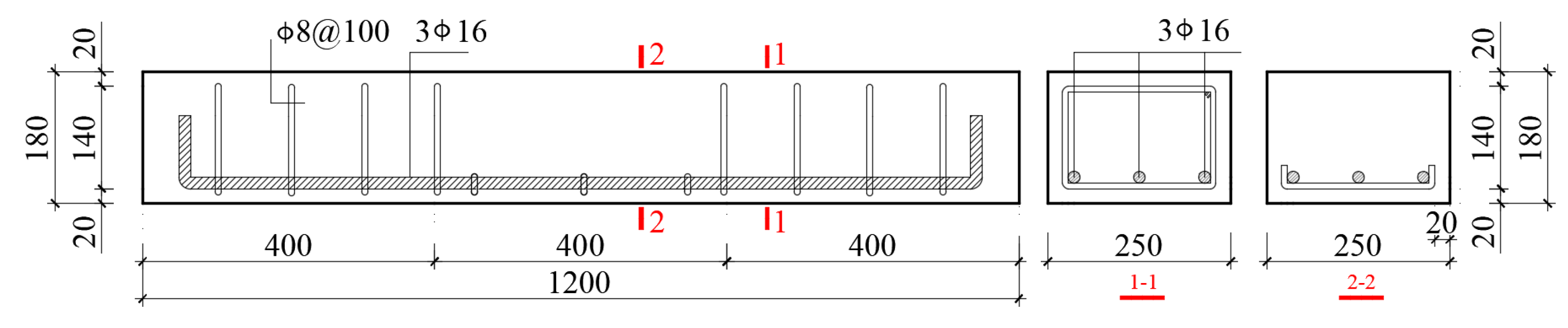
The model proposed in this paper is able to accurately predict the corrosion-induced cracking patterns of loaded reinforced concrete beams. Considering that the non-uniform steel corrosion in beam L00 and beam L60 interfere in the study of the influence from loading conditions, it is necessary to eliminate the interference factors. In this section, three simulated beams were set up, as shown in
Table 4. The material and size of the S-serial simulated beams are consistent with the experimental beams; except for the external loading conditions being set as the only variable, the other influencing factors are kept constant. The three loading conditions that the beams are subjected to, namely, 0%, 30%, and 60%, which are the ultimate loads under four-point loading, are considered separately. Subsequently, a uniformly distributed steel corrosion of the longitudinal bar is used as the input parameter, which increases at a rate of 0.1%/year for 30 years. After obtaining the calculated results, the effects of the external loads on corrosion-induced concrete cracking are quantitatively assessed in terms of the crack location, internal crack morphology, and concrete cover damage.
4.1. Surface Cracking Moment
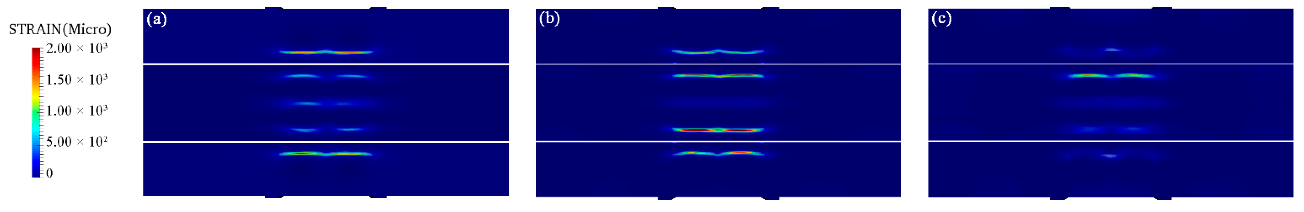
Figure 9 shows the strain induced by steel corrosion on the side and tension faces at the surface cracking moment. The position with higher strains is rendered in red and that with lower strain is in yellow, green, and blue.
As shown in
Figure 9, the steel corrosion of the longitudinal bars corresponding to the surface cracking moment ranges from 1.1% to 1.2% for 0%, 30%, and 60% ultimate loads conditions, where the difference is more than 9%, thus showing a higher similarity. This phenomenon indicates that the external loads do not have significant effects on the steel corrosion corresponding to the surface cracking moment. However, the strain distribution on the beam surface varies in different conditions. The strain on the side face is far greater than that on the tension face of the beam S-L00, suggesting that at the surface cracking moment, the corrosion-induced crack first occurs on the side of the beam as the major crack. This phenomenon can be explained by the mechanism where the stress fields of different longitudinal bars cancel out each other to some extent. Considering the fracture energy theory, the probability of an initial crack generation at the side and the tension face of the beam ought to be approximately equal due to the identical concrete cover thickness. However, the side face is mainly subjected to the corrosion-induced expansive force exerted by the corner longitudinal bars, while the tension face is subjected to the corrosion-induced expansive force exerted by all three longitudinal bars at the same time. The circumferential tensile stresses induced by one longitudinal bar may not develop in the same direction as the others, thus they are counteracted and the propagation of cracks is restrained.
Compared with the maximum strain on the tension face of beam S-L00 (8.25 × 10
−4), the strain due to corrosion-induced expansive force on the tension face of beam S-L30 (2.69 × 10
−3) is 226% greater, which can be attributed to the impacts of the load. Under four-point loading, the tension face of the beam is in biaxial tension, and is also the region with the greatest tensile stress induced by external loads, which is along the longitudinal direction. According to materials’ mechanics, the uniaxial tensile strength along the hoop direction is the lowest. Hence, the corrosion-induced crack tends to propagate towards the tension face [
9]. A similar phenomenon is also found in beam S-L60, showing that the strain on the tension face is also much greater than that on the side face.
It can be concluded that in concrete beams, corrosion-induced cracks are likely to first appear on the tension face under external loads, the tendency of which becomes more pronounced as the load increases. These findings are consistent with the opinion of Zhu, who investigated the surface cracking pattern of concrete beams subjected to coupled 80% ultimate loads and chloride attack [
31].
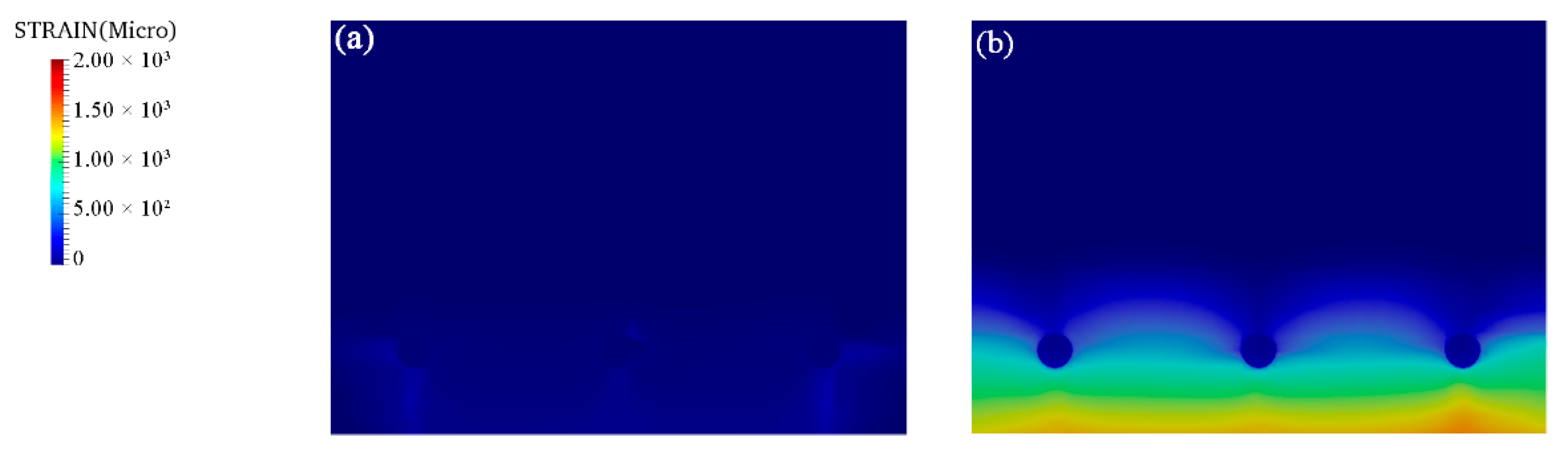
Moreover, the surface strain of beam S-L60 was slightly smaller than that of beam S-L30, indicating that the steel corrosion at the surface cracking moment of beam S-L60 was also smaller than beam S-L30. This phenomenon could be explained by the effect of external loads on mass transport in the pore structure, which is expressed in Equation (2). When the external loads exceed 60% of the ultimate load, concrete cover is severely damaged and provides a direct path for corrosion products diffusing outwards, as shown in
Figure 10. As a result, the proportion of corrosion product filling in the concrete rises, retarding the growth of the corrosion-induced expansive force. In contrast, for beam S-L30, the load-induced cracks do not penetrate the concrete cover thickness, the rate of corrosion products transporting outwards remains nearly unchanged, and the growth of the corrosion-induced expansive force is not affected.
It can be concluded that the effects of external loads on the surface cracking moment include the positive effects due to stress superposition, and negative effects due to the restraint of corrosion product accumulation on the steel surface, showing a dual characteristic. With the same corrosion rate, the moment of corrosion-induced surface cracking of concrete beams under extreme loads is not always earlier than that under moderate loads. In other words, the surface cracking moment depends on which effect is dominant.
4.2. Serviceability Limit State
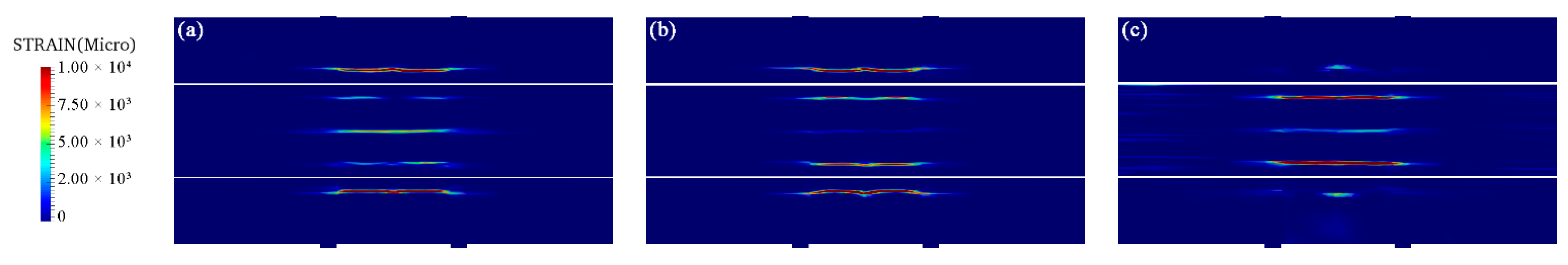
According to the Standard for Design of Concrete Structure Durability (GB/T 50476/2019), the serviceability limit state corresponds to 0.1 mm corrosion attack of the steel bar. By considering that the diameter of the longitudinal bar in the beams is 16 mm, beams reach the serviceability limit state when steel corrosion exceeds 2.5 %. For this state, the surface cracking pattern is shown in
Figure 11. The main crack of beam S-L00 is located on the side face, while the main crack of beam S-L60 is located on the tension face. In contrast to the condition at the surface cracking moment, corrosion-induced cracking on the surface of beam S-L60 is more severe than that of the S-L00 and S-L30 beams at the serviceability limit state. The maximum strain of the former is 2.52 × 10
−2, and the equivalent crack widths are 1.22 and 1.14 times that of the latter, respectively. In this state, corrosion-induced cracks that are parallel to the longitudinal bar provide additional paths for corrosion products being transporting outwards, thus masking the effect of load-induced cracks retarding the growth of the corrosion-induced expansive force. Therefore, after surface cracking moment, the condition of external loads is the dominant factor in corrosion-induced crack propagation.
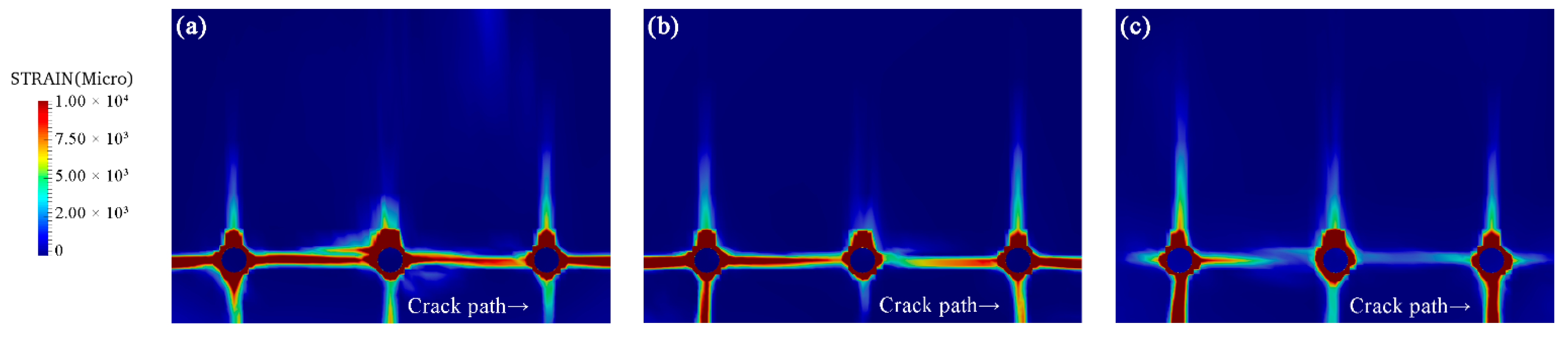
The prominent effects of external loads on expediting corrosion-induced crack propagation in tension face are also reflected in the internal cracking pattern, as shown in
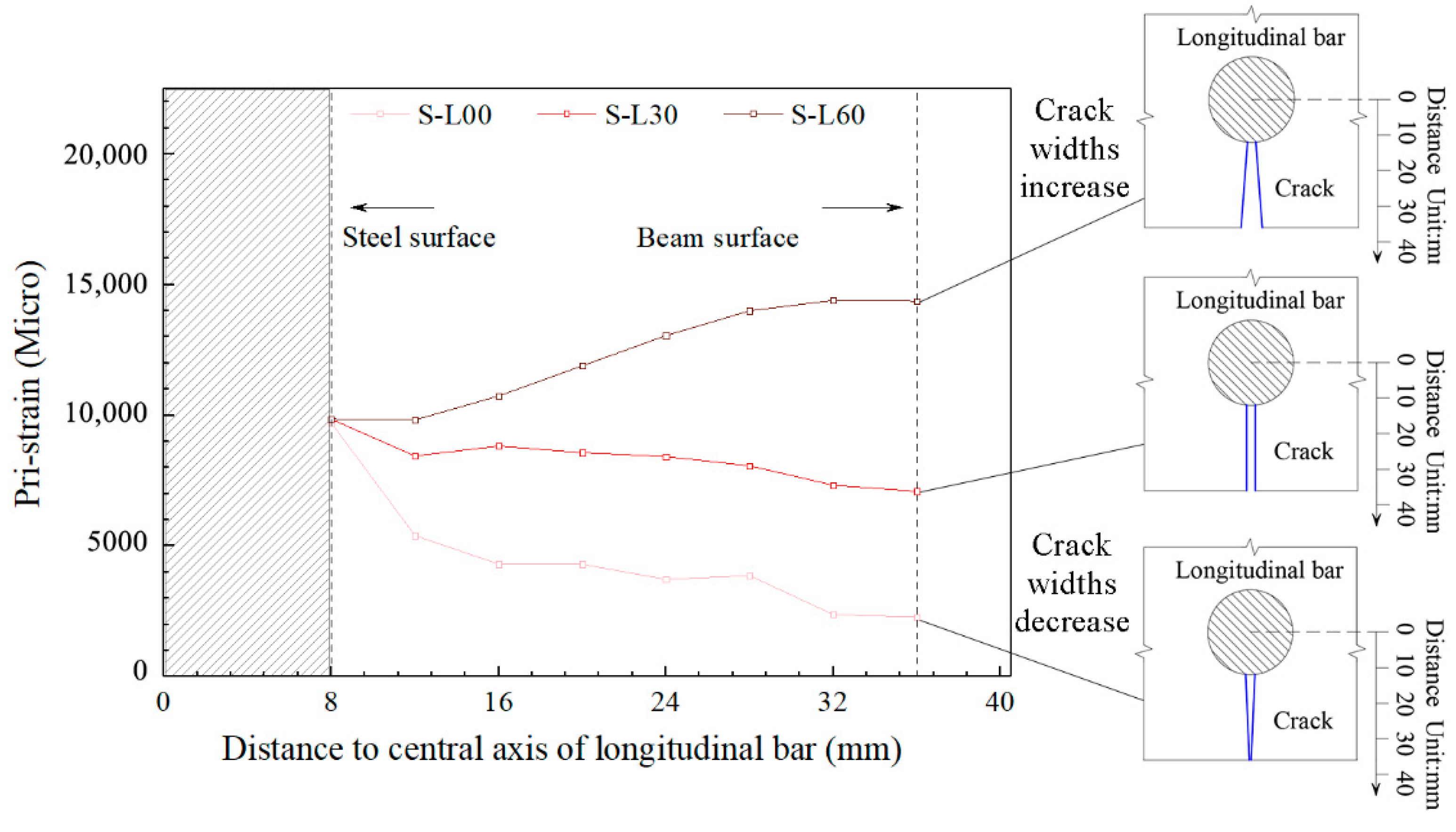
Figure 12. It should be noted that the beam section in the middle of the two adjacent stirrups is chosen as a research object to avoid the interference from the stirrups. Then, the principal strain along the vertical crack path, marked by an arrow, is extracted, representing the potential crack width distribution, as shown in
Figure 13. Because of the identical set of corrosion distributions in these three simulated beams, the crack widths on the steel surface under different load are much the same. The difference is that the shape of the crack varies under different load conditions. When there is no external load, the crack widths decrease along the path, showing the shape of an inverted triangle. This phenomenon can be attributed to the attenuation of corrosion-induced stress as the distance to steel surface rises, which is always found in the state before surface cracking [
32]. Under 60% of the peak load, the crack expands along the path and shows the shape of a trapezoid. Obviously, this phenomenon is due to the positive gradient of load-induced stress along the crack path, leading the load-induced damage in concrete becoming more severe when being close to beam surface. Moreover, the relation between the internal cracking pattern and surface crack widths is clearly reflected in the above analysis, i.e., the shape of the internal corrosion-induced cracks controls the widths of the surface crack.
Compared with those corrosion-induced cracks that propagate from the steel surface to the beam surface, horizontal cracks do not connect the external environment with the longitudinal bar, and have little influence on the corrosion rate. However, as shown in
Figure 12a, the horizontal cracks connecting two adjacent longitudinal bars in beam L00 together with the vertical load-induced cracks may split the section into multiple parts, weakening the cohesion in the concrete and leading to a risk of layer spalling in the tension zone [
33,
34].
In contrast, there are almost no horizontal cracks in beam S-L60. This phenomenon can be explained in two ways. First, the severe load-induced damage in the tension zone leads the corrosion-induced cracks tending to propagate towards the tension face. Second, the corrosion products tend to be transported along the direction the cracks propagate, resulting in a concentration of corrosion products at the side near the tension face. The concentrated corrosion products cause the non-uniform expansive force, releasing the force at the other sides. In conclusion, external loads affect the characteristics of corrosion-induced cracking and will result in different modes of structural failure.
5. Conclusions
The effect of external loads on the surface cracking moment is not significant, the differences in steel corrosion corresponding to the surface cracking moment do not exceed 9% for different loading conditions. This phenomenon is mainly due to the dual effects of external loads on corrosion-induced cracking. The loads cause concrete damage, weakening its resistance against corrosion-induced expansive force, expediting corrosion-induced cracking. At the same time, load-induced cracks provide paths for corrosion products to be transported outwards, retarding the growth of the corrosion-induced expansive force.
External loads significantly alter both the surface cracking pattern and the internal cracking one. The damage induced by load reduces the uniaxial tensile strength of the concrete, leading to corrosion-induced crack tending to propagate through the damaged zone. For beam surfaces, cracks induced by steel corrosion tend to first occur on the tension face and develop into the main crack. For the internal part, the development of horizontal cracks between the adjacent longitudinal bar is restrained.
After surface cracking, the rate of crack propagation is proportional to the load level. At the serviceability limit state, the maximum width of corrosion-induced cracks of beams subjected to 60% ultimate load is 1.14 and 1.22 times that of the beams subjected to 30% and 0% ultimate load, respectively. In this state, the corrosion-induced cracks that are parallel to the longitudinal bars provide more paths for corrosion product transport, and the external loads accelerate the development of corrosion-induced cracking.


