1. Introduction
Shear walls offer great lateral stiffness and good integrity as the primary component of a high-rise construction that resists lateral forces. The three primary types of shear wall are steel plate shear wall, steel plate concrete composite shear wall, and reinforced concrete shear wall. Under the influence of horizontal force, the reinforced concrete shear wall has a modest lateral displacement and a high degree of stiffness. However, as the building’s height increases, the reinforced concrete shear wall will add to the structure’s overall weight, increasing the vertical stress on the bottom shear wall and decreasing the structural ductility. The steel plate shear wall exhibits steady hysteretic characteristics and high plasticity. Compared with reinforced concrete shear wall, it has better ductility, lighter self-weight and faster construction speed. However, in the event of a powerful earthquake, the steel plate shear wall will clearly show stress concentration, which could result in localized structural damage.
The steel plate concrete composite shear wall combines the benefits of reinforced concrete shear wall and steel plate shear wall, providing improved shear resistance, plasticity, ductility, and good energy dissipation capacity. It is a hybrid structure made of steel plate and concrete with connectors like studs and tension bolts [
1]. The steel plate can enhance the shear-bearing capacity of the wall while constraining the lateral expansion of the concrete, maintaining the integrity of concrete and delaying the time of its damage. The local buckling of steel plates refers to excessive local deformation, a decrease in out-of-plane stiffness, and a decrease in load-bearing capacity. As a lateral support for the outer steel plate, concrete can restrict its local buckling, maintain the stiffness and stability of the structure, and ensure the service life of the structure [
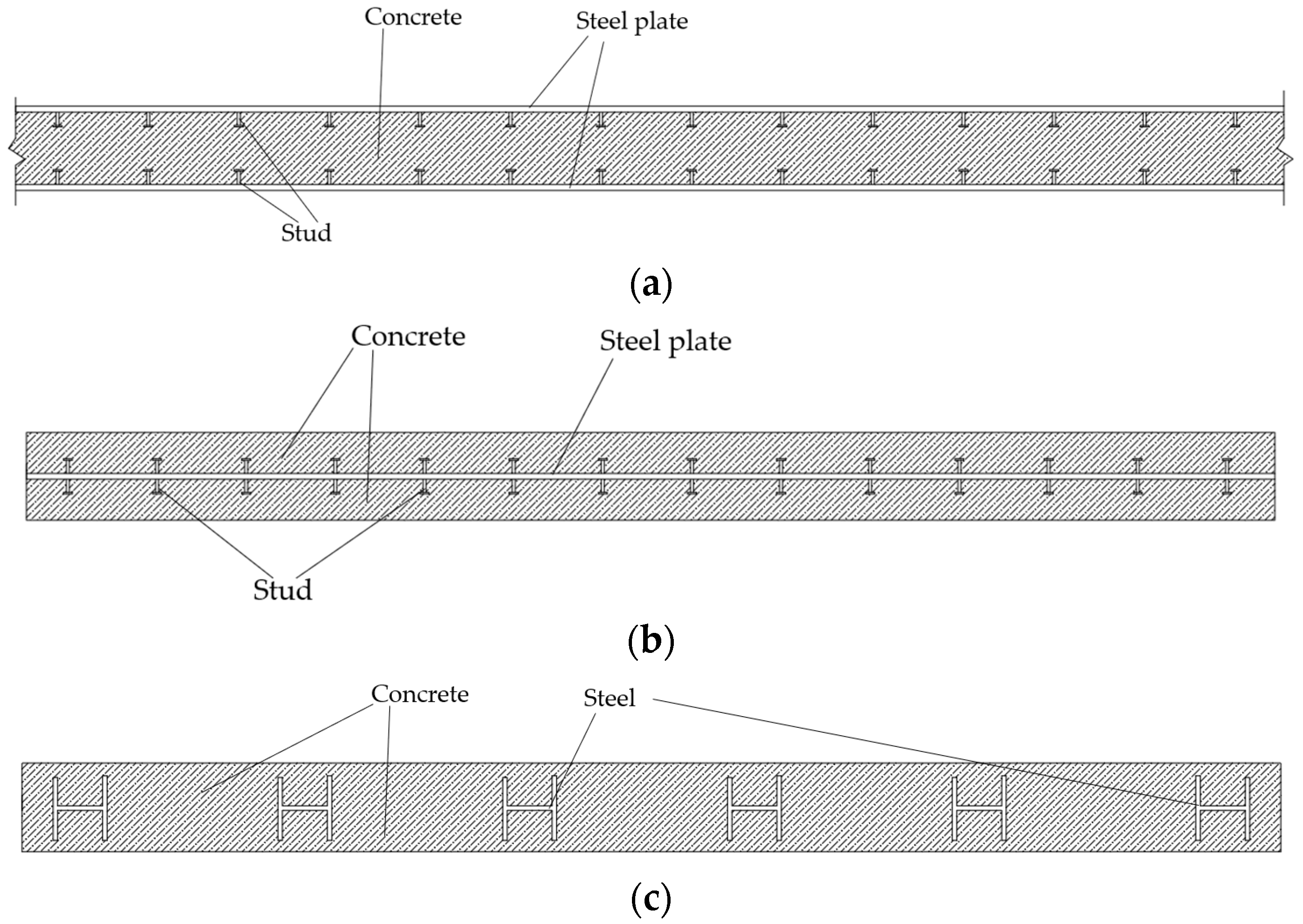
2]. Steel reinforced concrete composite shear wall, single steel plate concrete composite shear wall, and double steel plate concrete composite shear wall are among the different varieties of steel plate concrete composite shear walls, as illustrated in
Figure 1. The steel plate and filled concrete can cooperate to exhibit good bearing capacity, stiffness, hysteresis performance, ductility, and energy dissipation capacity [
3]. Before the double steel plate concrete composite shear wall reached the bearing capacity, there was no steel plate buckling. Therefore, the double steel plate concrete composite shear wall is a relatively new form of this structure and is widely used in buildings with over-limit or super-tall structural requirements.
The finite element method is a popular tool in structural engineering because it can be used to simulate how steel and reinforced concrete structures would respond to different loads. Ultra-high performance concrete (UHPC) and steel bars conducted an experimental research on the local bond stress, which Ahad Amini Pishro et al. [
4] simulated using ABAQUS. The outcomes demonstrate that there is a good degree of consistency between the experimental and the ABAQUS simulation results. Relying on finite element software ABAQUS, version 2023.Ahad Amini Pishro [
5] and associates verify the outcomes of reinforcing reinforced concrete T-beams with FRP. For artificial neural network-based structural response prediction, a set of precise numerical databases is offered. Dong Chen [
6] and colleagues investigate and simulate the steel plate concrete coupling beam using ABAQUS’s plastic damage model of concrete; the simulation findings show good agreement with the experimental data. ABAQUS was utilized by Nam H. Nguyen and associates to do numerical analysis on the steel plate and concrete composite wall [
7]. The research shows that the influence of reinforcement ratio, connector type and panel slenderness ratio on the seismic performance of the wall can be realized by ABAQUS. Using ABAQUS finite element modeling method, Lu Dong et al. [
8]. analyzed the influence of the ratio of height to thickness of steel plate on the performance of partially connected steel plate shear wall with four unstiffened sides, and studied the effects of three different forms of stiffening ribs on partially connected steel plate shear wall.
There are already engineering examples of steel plate concrete composite shear wall in China. The Guangzhou East Tower has employed embedded steel plate concrete composite shear wall [
9]. Double steel plate concrete composite shear walls are used in the primary structure of Yancheng, Jiangsu Province’s radio and television tower [
10]. However, the research on the overall structural design of steel plate concrete composite shear wall is relatively lacking in practical engineering. This is not conducive to the promotion and development of double steel plate composite shear walls in building structures. The seismic performance of a double steel plate concrete composite shear wall in practical engineering is therefore analyzed in this paper using YIK V5.3.0, ABAQUS 2023, and MIDAS GEN2022 finite element software. The research results can therefore compensate for the lack of existing literature and offer some recommendations for the seismic design of a double steel plate concrete composite shear wall.
2. Project Overview
The R&D building of Zhanjiang Bay Laboratory is located in Potou District, Zhanjiang City, Guangdong Province. The total building area of the main building in Zone II of the project is approximately 37,000 square meters, with a building height of 46.5 m, consisting of 10 floors and one basement level. The architectural structural rendering can be seen in
Figure 2a. The selection of the structural system is found in reference [
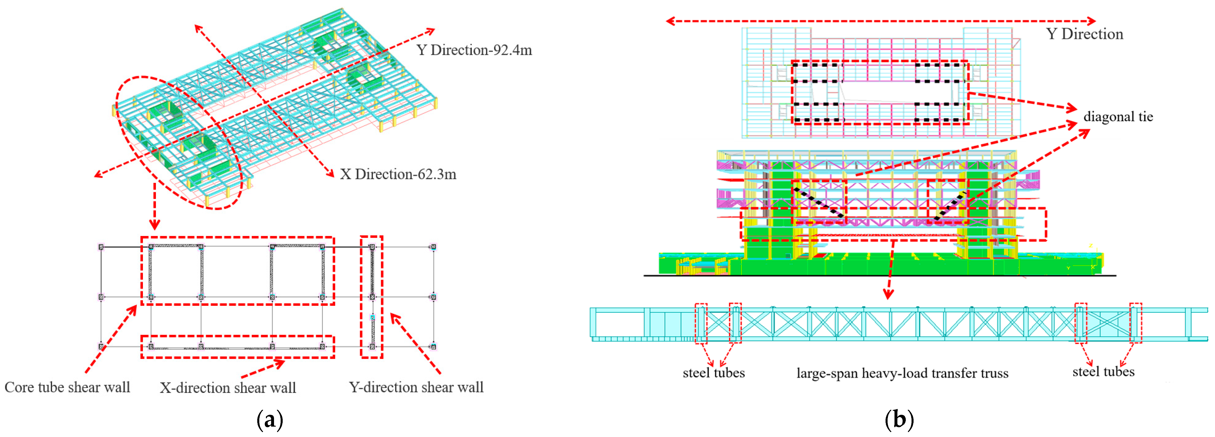
11], where various structural systems were compared for their pros and cons and calculations were conducted. Eventually, a truss-style conversion structure was chosen for the transition layer, and a steel frame-shear wall structure was selected as the structural system scheme for this project. The model of the steel frame-shear wall structure is shown in
Figure 2b.
Figure 3b illustrates the location of the large-span and heavy-load transfer truss, which supports the top frame, on the fourth level above the ground. The large-span and heavy-load transfer truss is welded together with the steel tubes of the side columns of the shear walls and other columns.
Double steel plate concrete composite shear walls, as important components of this structure, are distributed in the core tube and the perimeter of the entire structure, and are primarily classified into three categories: double steel plate concrete composite shear walls at the core tube, double steel plate concrete composite shear walls in the X direction, and double steel plate concrete composite shear walls in the Y direction.
Figure 3a shows the arrangement of the double steel plate concrete composite shear walls on the third floor, with the X direction being 64.3 m and the Y direction being 92.4 m. The basic parameters of the double steel plate concrete composite shear wall on the third floor are shown in
Table 1.
Considering the overall lateral stiffness of the structure, the strengthened zone at the base of the structure spans from the 1st to 6th floors. The large-span and heavy-load transfer truss and diagonal tie rods of this structure are connected to the core tube and continue to the tenth floor, so the stress on the core tube is very large, and the stress in other directions is small. Therefore, the double steel plate concrete composite shear walls at the core tube are symmetrically arranged up to the 10th floor above ground in both X and Y directions, while they extend to the third floor above ground in both X and Y directions. The double steel plate concrete composite shear walls end columns are filled with concrete up to the 10th floor above ground, while the other frame columns are filled with concrete up to the 4th floor above ground.
3. Dynamic Elastoplastic Analysis under Major Seismic Effects
Because of the unfavorable characteristics of the structure, such as irregular torsion and discontinuous components, it is necessary to carry out dynamic elastic-plastic time-history analysis under the action of large earthquakes. Using the YJK V5.3.0. building structure calculation software, the comprehensive indexes such as the base shear force and displacement angle of the structure under a strong earthquake, as well as the internal force and plastic damage of a double steel plate concrete composite shear wall, are studied.
3.1. Dynamic Elastoplastic Analysis
3.1.1. Wave Selection
Firstly, the required target response spectrum is determined by the basic structural parameters and site characteristics, and then the seismic wave matching the target response spectrum is selected. According to the provisions of “Technical Specifications for Concrete Structures of High-rise Buildings” [
12] and “Code for Seismic Design of Buildings” [
13] the difference between the average response spectrum of the selected seismic waves and the target response spectrum at the main periodic points of the structure are not more than 20%.
According to Article 5.5.1 of the “Technical Specifications for Concrete Structures of High-rise Buildings” the principle of wave selection and calculation index values for dynamic elastoplastic analysis are the same as those for elastic time-history analysis as stipulated in Article 4.3.5 [
12]. Based on the requirements of the three elements: structural period, site conditions, and seismic motion, two natural waves Big Bear-01_NO_908, Tg (0.50); Chi-Chi, Taiwan-04_NO_2727, Tg (0.50), and one artificial wave Artwave-RH3TG055, Tg (0.55) are selected from the YJK seismic wave library.
3.1.2. Results of Dynamic Elastoplastic Analysis
Upon calculation, the maximum base shear of the structure is shown in
Table 2, and the maximum inter-story drift angle is in
Table 3. From
Table 2, it is known that under the effect of three groups of seismic waves, the maximum base shears in the X and Y directions are 151,782.65 kN and 181,731.10 kN, respectively, with the corresponding ratios of major seismic base shear to minor seismic base shear being 6.39 and 6.02. This section primarily focuses on a detailed analysis of the results for Chi-Chi, Taiwan-04_NO_2727, which has a larger response.
Table 3 shows the elastoplastic deformation of the structure under major seismic effects. The maximum displacement angle occurs at the tenth floor in the X direction. It shows that the tenth floor is weak and needs to be paid attention to during the construction stage and after the structure is completed. The maximum displacement angle reaches 1/239, less than 1/100 of the limit specified in the “Code for Seismic Design of Buildings” [
13]. This result shows that the whole structure is in a safe range.
3.2. Verification of the Load-Bearing Capacity of Double Steel Plate Concrete Composite Shear Walls
The maximum base shear force reflects the situation that the structure is impacted by earthquake in the horizontal direction. The maximum inter-story displacement angle reflects the magnitude of the inter-story displacement of the structure and determines the inter-story stability of the structure. These two indicators are too large to indicate that the structure is greatly impacted by seismic waves.
As shown in
Figure 4a, under the action of a large earthquake, for the overall structure, the double steel plate concrete composite shear wall with the highest shear force is located in the Y direction of the first floor above the ground, with a shear force value of 42,082.05 kN. As shown in
Figure 4b, for the core tube, the double steel plate concrete composite shear wall with the highest shear force is located in the X direction of the sixth floor above the ground, with a shear force value of 31,665.34 kN. The maximum shear force of the shear wall at this location is due to the addition of eight diagonal tie rods in this project to reduce the vertical displacement of the large-span truss in the transfer layer. However, the setup of the diagonal tie rods will also significantly increase the shear force and bending moment of the shear wall of the core tube on the sixth floor above ground, to which they are connected. The layout of the diagonal tie rods is shown in
Figure 3b.
Under the effects of a major earthquake, the locations of the maximum bending moments for both the overall structure and the double steel plate concrete composite shear walls at the core tube coincide with
Figure 4, with the maximum bending moment values being 333,981.03 kN·m and 85,301.16 kN·m, respectively. If the bending moment is too large, the shear wall will easily lose its stability out of plane. The other connected members are greatly displaced. The internal force of the whole structure will be redistributed and the safety of the structure will be threatened. According to the requirements of the “Technical Specifications for Steel Plate Shear Walls” the design values for the shear-bearing capacity of double steel plate concrete composite shear walls are calculated according to Equation (1) [
14], and the bending-bearing capacity design values are calculated according to Equations (2)–(4) [
14]. The calculated results are shown in
Table 4. Upon verification, they all meet the standard requirements.
4. Finite Element Analysis of Double Steel Plate Concrete Composite Shear Wall
The double steel plate concrete composite shear wall Wall-1 in the Y direction, rigidly connected to the large-span heavy-load transition truss. Wall-1 is at the edge of the structure in both X and Y directions of the four floors. Although it is connected to the truss, it has fewer constraints in-plane and out-of-plane than other shear walls. At the same time, the diagonal rod also gives Wall-1 a great tension. Therefore, Wall-1 is selected for stress performance analysis under major seismic effects using the finite element software ABAQUS. The spatial position schematic diagram of Wall-1 is shown in
Figure 5a.
4.1. Establishment of Finite Element Analysis Model
Wall-1 is composed of steel plates on both sides, concrete, with surrounding constraint components such as beams and columns. As a solid element, compared with the shell element, C3D8R element can well reflect the displacement and stress of the structure in all directions under load. In order to better obtain the response of Wall-1 under the influence of a major earthquake, all components are simulated using the C3D8R element, and refined mesh division is used for complex parts of the model. The schematic diagram of the model grid is shown in
Figure 5b.
All steel parts of Wall-1 are welded together, so when setting up interactions in ABAQUS, binding constraints are used to simulate welding. The contact relationship between steel plates and concrete, as well as steel tubes and internally poured concrete is such that they can separate but not penetrate each other in the normal direction, in ABAQUS, the hard contact model can simulate this relationship. There can be some friction allowing relative sliding in the tangential direction; this contact relationship is similar to the sliding friction, in ABAQUS, the Coulomb friction model can serve such friction relations. According to the comparison between the test and the finite element in Reference [
15], it is found that the friction coefficient of 0.6 can get better results.
After a YJK calculation, the force and boundary of each member in the structure are known. By selecting the analysis object, you can extract the force acted by the connected components on the object. The boundary conditions are determined according to the connection conditions of members.
The entire bottom of Wall-1 is consolidated. In Wall-1, the concrete uses C40. Steel materials other than profiled steel connectors use Q420B, and profiled steel connectors use Q235B. As shown in
Figure 6, the constitutive model of concrete is chosen as a plastic damage model, and the constitutive model of steel uses a double linear elastic-plastic reinforcement model without stiffness degradation [
15]. The load on Wall-1 is applied according to the actual stress situation. The internal forces of the relevant components under the effect of a major earthquake are extracted from the YJK calculation results.
Figure 7a depicts the load applied to Wall-1 in detail. The pressure adds to the axial pressure of the wall. To realize the influence of the remaining components on the wall, the coupling point is established on the remaining components, and the load is applied to the wall in the form of focused force.
4.2. Finite Element Calculation Results and Analysis
Under the influence of a major earthquake, the least favorable load was applied to Wall-1. After calculation, the internal forces, plastic damage, and displacement of Wall-1 under the least favorable load during a major earthquake scenario are shown in
Figure 7b,
Figure 8,
Figure 9 and
Figure 10.
As can be seen in
Figure 7b, the maximum stress in the steel components occurred at the junction of the steel plate and frame beam 7 with column 1, with the maximum stress being 353.6 MPa. The stress in other locations is relatively small, so the steel components remain in the elastic state.
Figure 8a demonstrates that the X-direction tensile stress and compressive stress of concrete are concentrated at the wall’s borders and middle. Concrete stress is mostly influenced by the edge steel pipes and steel plates on both sides.
Figure 8b shows the displacement cloud diagram of the double steel plate and concrete composite shear wall in the Y direction, with a maximum horizontal displacement of approximately 3.5 mm, and a displacement angle of 1/1285, far less than 1/100.
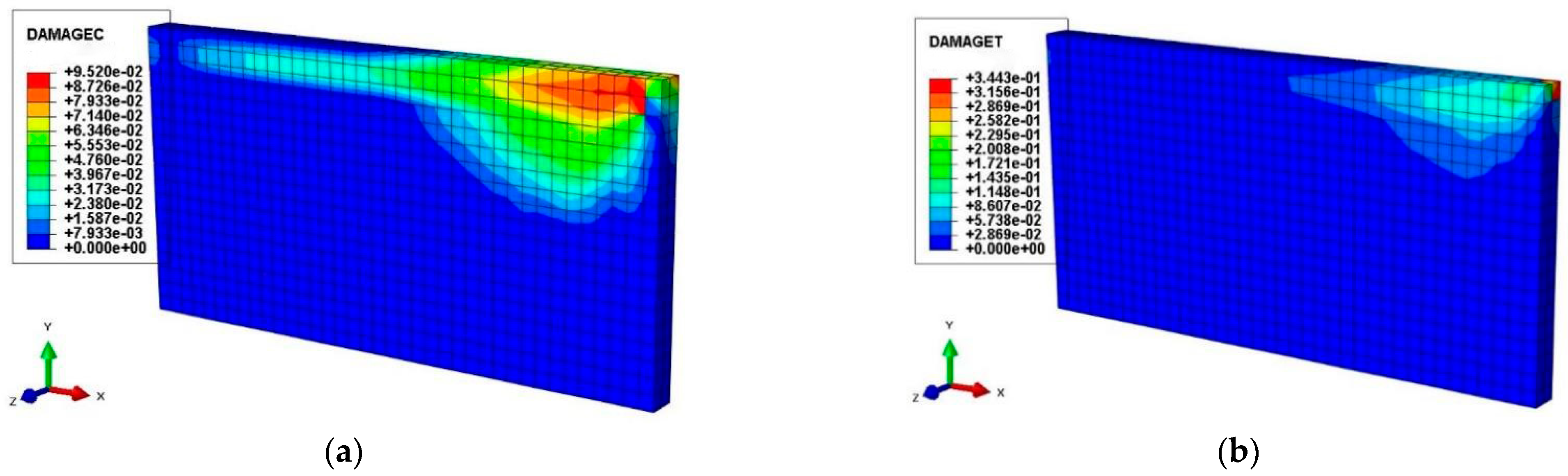
The failure of components is related to maximum deformation and cumulative damage, so it is necessary to select appropriate damage evolution parameters to describe the destruction caused by structural deformation and cumulative damage. In the concrete damage model, the compressive damage factor DAMAGEC and tensile damage factor DAMAGET in ABAQUS are usually selected to describe the damage degree of concrete. As shown in
Table 5, the higher the damage factor, the more serious the damage.
Combining
Table 5 with
Figure 9 and
Figure 10, it can be seen that the maximum cumulative compressive damage of the concrete inside the frame beams and columns is relatively small, below moderate damage; the cumulative tensile damage to the concrete is categorized as minor damage. The process of tensile damage in concrete involves the partial destruction of concrete units inside the frame beams connected to the strengthening columns, followed by slight damage to the wall panel concrete units connected to the frame beams. The above analysis shows that Wall-1 can meet the design target requirements under the influence of a major earthquake.
5. Anti-Progressive Collapse Analysis of the Whole Structure
During the service life of a building structure, in addition to facing rare earthquakes, it may also be subjected to accidental loads such as explosion loads and impact loads. According to China’s CECS 392: 2014 “Building Structure Anti-Collapse Design Standard” [
16] progressive collapse of a structure refers to the process that starts with the initial local failure and extends to component damage, eventually leading to the collapse of a part or the entire structure. Since this structure may be exposed to various overload conditions, this paper carries out an analysis of the structure’s resistance to progressive collapse. Since the progressive collapse of a structure is a dynamic process, and nonlinearity also exists within this process [
17], the nonlinear dynamic method is chosen in this paper to accurately reflect the dynamic response of the structure at the moment of component failure.
The design methods of anti-progressive collapse include the tie strength method, the local enhanced resistance method and the component removal method. The first two are strength checking or strengthening of key components, and do not focus on the response of the remaining structure. The demolition component method is the most commonly used method in structural progressive collapse resistance design. The method is to ‘remove’ the vertical members of the initial support, so that the internal force redistribution of the remaining structure occurs under the action of the original vertical load, and then judge whether the structure has sufficient frame capacity to resist progressive collapse.
5.1. Position of Component Removal
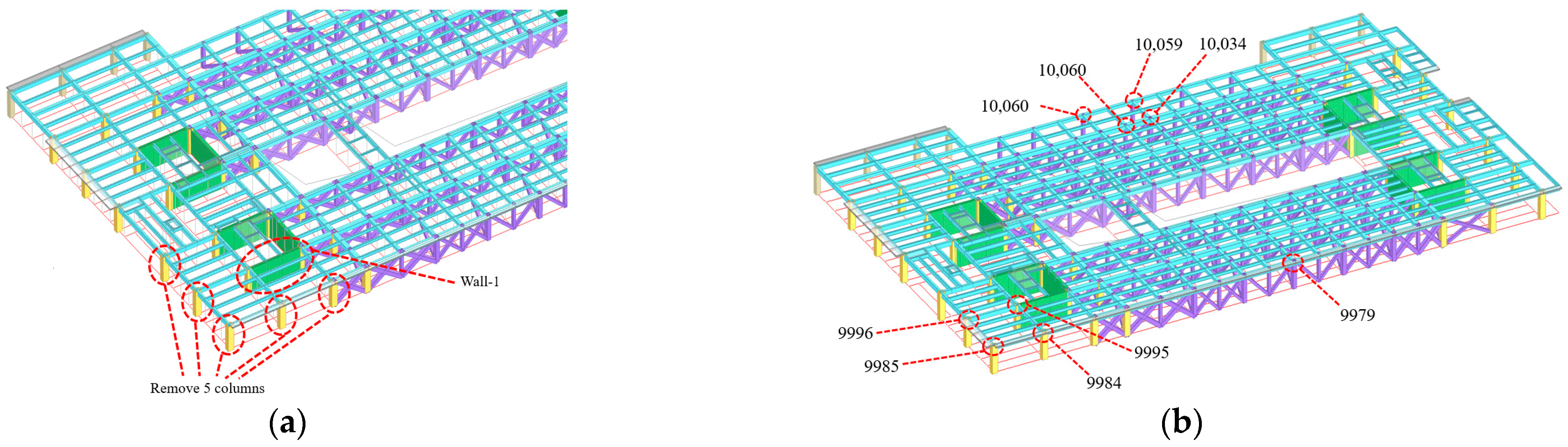
This paper mainly explores the resistance to progressive collapse of the overall structure and the dynamic response of the typical double steel plate and concrete composite shear wall after the removal of components. In accordance with the standard requirements and considering the specific characteristics of the project, the paper chooses the short-side middle columns, long-side middle columns, corner columns, and internal columns surrounding Wall-1 of the typical double steel plate and concrete composite shear wall on the four above-ground floors, where the large-span heavy-load transfer truss is located, as single-column removal objects, as shown in
Figure 11a.
Since there is a likelihood of multiple columns being simultaneously impacted in the event of a collision or explosion, the paper also chooses the short-side double columns and long-side double columns surrounding Wall-1 as dual-column removal objects, as shown in
Figure 11b. Similarly, considering extreme situations, the paper selects the five columns surrounding Wall-1 for removal as shown in
Figure 12a, and compares this scenario with the previous two situations.
Figure 12.
(
a) Demolition of five columns. (
b) The corresponding node location diagram in
Table 6.
Figure 12.
(
a) Demolition of five columns. (
b) The corresponding node location diagram in
Table 6.
5.2. The Failure Criterion of Anti-Progressive Collapse Dynamic Analysis
GSA2016 [
18] stipulates that when the nonlinear dynamic method is used to calculate the progressive collapse resistance of steel frame structures, the rotation angle limit of the remaining horizontal members of the structure is 12°. If the rotation angle exceeds 12°, the component will have a large displacement, causing the remaining connected components to lose stability. At this time, progressive collapse of the structure will occur. The calculation rule of the rotation angle of the horizontal member is shown in Equation (5), where
θ is the rotation angle, which is the absolute value of the maximum vertical displacement of ∆, and
lbeam is the minimum span of the adjacent beam. ∆/
lbeam is the tangent value of
θ.
5.3. Results of Anti-Progressive Collapse Analysis
5.3.1. Analysis of Node Displacement Results
The vertical displacement time-history curves for the nodes after the removal of a single column, two columns, and five columns are shown in
Figure 13 and
Figure 14, with negative vertical displacement indicating downward movement. As illustrated in the figures, regardless of the type of removal scenario, the vertical displacement of the nodes above the removed columns rapidly increases to a maximum value in a very short time, then oscillates back and forth, ultimately reaching a stable value.
Table 7 tabulates the maximum vertical displacement of the nodes and the corresponding angles calculated using Equation (5) for each scenario. After removing the column, the node moves down rapidly due to the gravity above. In the later stage, due to the pulling effect of other components, the node will reach a stable state after a large swing. If this swing exceeds the limit of the structure, progressive collapse will occur.
From
Table 7, it can be seen that when a single column is removed, the corner column exhibits the largest displacement, reaching 62.00 mm, with an angle of 0.42°; when two columns are removed, column 1 of the short side double column shows the largest displacement, reaching 90.60 mm, with an angle of 0.62°; when five columns are removed simultaneously, the corner column exhibits the largest displacement, reaching 296.10 mm, with an angle of 2.02°. According to the analysis, the simultaneous removal of five columns results in the largest displacement at the nodes above the removed columns, and the corresponding angle is also the largest, but it is far less than the prescribed limit of 12°.
Since this project differs from typical frame structures and includes a large-span heavy-load transfer truss designed at the fourth above-ground level, it is necessary to examine the node displacement of each column across the entire four floors. Due to space limitations, the author provides displacement information for some critical nodes, taking the case of corner column removal in the single column removal scenario as an example.
Table 6 summarizes the nodes with a peak displacement rate change greater than 50% and peak displacement greater than 100 mm (peak displacement rate change = (peak displacement − initial displacement)/initial displacement), with a negative sign indicating vertical downward movement. The locations of the corresponding nodes are shown in
Figure 12b.
It can be seen in
Table 6 that there are four nodes with the peak displacement rate change is greater than 50%. Among them, node 9985 has the highest peak displacement rate change, reaching 702.65%, and this node is precisely the upper-end node of the removed column. The other three nodes are not much different, hovering around 60%, and these three nodes are exactly the upper-end nodes of the three columns closest to the removed column; simultaneously, the peak displacements of these three nodes are all relatively small, below 5 mm.
There are five nodes with a peak displacement greater than 100 mm, all located in the span of the large-span heavy-load transfer truss, with the maximum peak displacement of 120.48 mm at node 10,059. On the other hand, the peak displacement rate change corresponding to the five nodes with peak displacement greater than 100 mm is relatively small, below 1%, indicating that the removal of the corner column has little effect on the displacement of the large-span heavy-load transfer truss. At the same time, the stable displacement rate change (stable displacement rate change = (stable displacement − initial displacement)/initial displacement) of all five nodes is negative, indicating that after the corner column is removed, its displacement is further reduced.
The above analysis indicates that, regardless of the column removal scenario, the corresponding rotation angle at the removal location has not exceeded the limit, and the overall structure has not experienced progressive collapse. Regarding nodal displacement, the removal of a column has a more significant impact on the columns around it and a lesser impact on those far from it. Although the displacement in the span of the large-span heavy-load transfer truss is relatively large, the effect of removing the corner column on it is minimal. Compared to before the removal, its displacement will even decrease. The reason for this may be that after the corner column is removed, the sudden increase in displacement in its upper structure creates a “tie effect” on the central part of the span in the large-span heavy-load transfer truss.
5.3.2. Dynamic Response Analysis of Typical Double Steel Plate Concrete Composite Shear Wall
Figure 15 and
Figure 16a are the shear time history curves of Wall-1 under the conditions of removing single column, double columns and five columns. The negative sign indicates that the direction of the coordinate axis is opposite. From the figures, it can be observed that at the moment of component removal, the shear forces in Wall-1 fluctuate rapidly, showing an overall decreasing trend, and then approach stability. In this process, Wall-1’s maximum shear force occurs in the scenario of removing five columns, reaching 14,676.8 kN. According to Equation (1), Wall-1’s shear-bearing capacity is 109,928.5 kN, far greater than 14,676.8 kN.
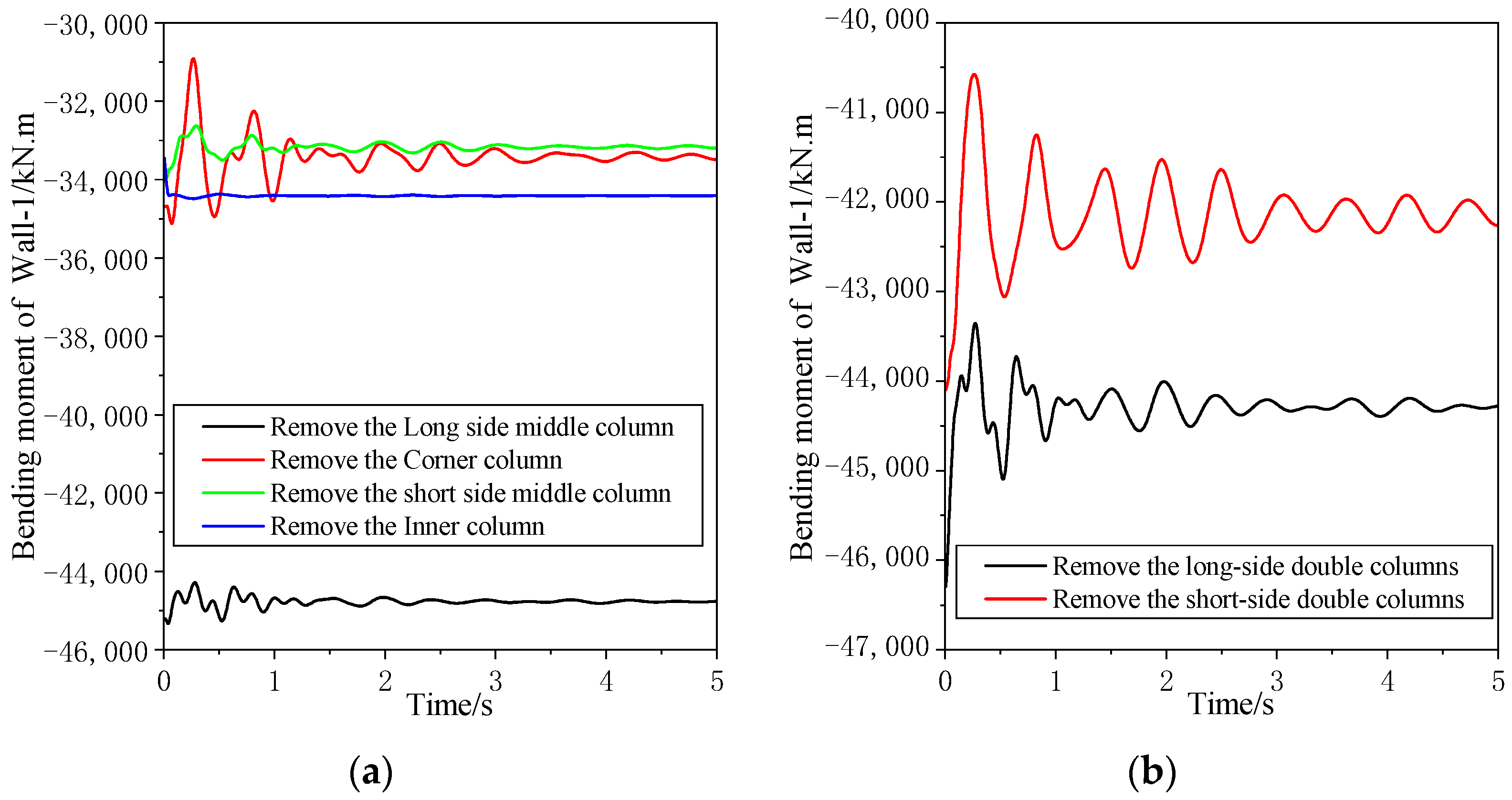
Figure 16b and
Figure 17 show the moment–time curves for Wall-1 during the removal of single, double, and five-column scenarios, where a negative sign indicates a direction opposite to the coordinate axis. From the figures, it can be seen that except for the scenario of removing the internal column, Wall-1’s moment shows a decreasing trend in the other scenarios. In this process, the maximum bending moment occurs in the scenario of removing five columns, reaching 49,560.7 kN·m. According to Equation (2) through (4), Wall-1’s bending-bearing capacity is 528,353.3 kN·m, far greater than 49,560.7 kN·m.
The excessive shear force of Wall-1 reflects that the in-plane components connected to Wall-1 are under great stress after the removal of the column, which needs to be paid attention to. The excessive bending moment of Wall-1 reflects that the out-of-plane deformation of Wall-1 needs to be controlled after the column is removed. Otherwise, the probability of collapse will increase. The above analysis indicates that, regardless of the column removal scenario, Wall-1’s shear force and bending moment both meet the specification requirements.
6. Conclusions
In this paper, the YJK, ABAQUS, and MIDAS finite element analysis software are used to analyze the Zhanjiang Bay Laboratory Research and Development Building. The seismic performance and application of a double steel plate concrete composite shear wall are mainly investigated. The following conclusions are obtained:
(1) Using the building structure calculation software YJK-EP, a dynamic elastoplastic time–history analysis was performed on the Zhanjiang Bay Laboratory Headquarters Research and Development Building under rare earthquake effects. The shear walls with the maximum shear force and bending moment were checked for shear and bending resistance, all of which meet the specification requirements.
(2) Abaqus finite element analysis software was used to select Wall-1, a double steel plate concrete composite shear wall connected with a large-span and heavy-load transfer truss on the fourth floor, for verification under large seismic action. The results indicate that the steel material of Wall-1 always remains elastic; concrete accumulative compression damage is minor and below moderate damage; concrete wall panel’s accumulative tensile damage is classified as minor damage; the horizontal displacement angle in the Y direction is 1/1285, far less than 1/100. The analysis demonstrates that Wall-1 can meet the design objectives under major seismic action.
(3) Through Midas-Gen finite element software and using nonlinear dynamic analysis methods, anti-progressive collapse analysis was performed on the overall structure, studying the integrity of the structure and Wall-1’s dynamic response after the removal of characteristic columns surrounding the typical double steel plate concrete composite shear wall Wall-1 on the above-ground four floors. The results show that in the seven scenarios, the remaining structural horizontal member’s maximum rotation angle is 2.02°, far less than the limit of 12°, with no occurrence of progressive collapse. Wall-1’s maximum shear and bending moments are both far less than its shear and bending capacity, meeting the bearing capacity requirements. The removal of corner columns has a significant impact on the displacement of nearby columns on the same floor, with a peak displacement variation rate reaching 702.65%.
7. Possible Directions for Future Studies
The research in this paper mainly focuses on the application of a double steel plate concrete composite shear wall in building structures. The contents include the stress of the composite shear wall under the condition of a large earthquake, a refined finite element analysis of the two materials, and an analysis of the progressive collapse resistance of the structure.
In the future, we can do some more in-depth research in the direction of anti-progressive collapse. For example, we can take a typical substructure of this structure for experiment, and then verify it by the numerical method. Finally, the numerical method is used to do more parameter analysis and draw more systematic conclusions.
Author Contributions
Writing—original draft, T.L.; software, X.W.; investigation, Y.C.; methodology, X.L.; conceptualization, Y.Y. All authors have read and agreed to the published version of the manuscript.
Funding
This study was supported by the CSSC International Engineering Co., Ltd. Technological Innovation and research and development project (CN), Award Number: 20MT01J and the CSSC International Engineering Co., Ltd. Technological Innovation and research and development project (CN), Award Number: 20MT07J.
Data Availability Statement
The data presented in this study are available in the article.
Conflicts of Interest
Authors Tao Lan and Xin Liu were employed by the company CSSC International Engineering Co., Ltd. The remaining authors declare that the research was conducted in the absence of any commercial or financial relationships that could be construed as a potential conflict of interest. The authors declare that this study received funding from CSSC International Engineering Co., Ltd. The funder had no role in the design of the study; in the collection, analysis, or interpretation of data, in the writing of the manuscript, or in the decision to publish the results.
References
- Tsai, K.C.; Lin, Y.C.; Lin, C.H. Seismic Responses and Design of Steel Plate Shear Wall. Prog. Steel Build. Struct. 2007, 9, 19–25. [Google Scholar]
- Stephens, M.J.; Zimmerman, T.J. The strength of composite ice-resisting walls subjected to combined loads. Aztex Corp. 1990, 25, 189–207. [Google Scholar]
- Nie, J.; Tao, M.; Fan, J.; Bu, F.; Hu, H.; Ma, X.; Li, S.; Liu, F. Research advances of composite shear walls with double steel plates and filled concrete. Build. Struct. 2011, 41, 52–60. [Google Scholar]
- Pishro, A.A.; Feng, X.; Ping, Y.; Dengshi, H.; Shirazinejad, R.S. Comprehensive equation of local bond stress between UHPC and reinforcing steel bars. Constr. Build. Mater. 2020, 262, 119942. [Google Scholar] [CrossRef]
- Pishro, A.A.; Zhang, Z.; Pishro, M.A.; Liu, W.; Zhang, L.; Yang, Q. Structural Performance of EB-FRP-Strengthened RC T-Beams Subjected to Combined Torsion and Shear Using ANN. Materials 2022, 15, 4852. [Google Scholar] [CrossRef] [PubMed]
- Chen, D.; Fan, C.; Song, L. The Numerical Simulation for Steel Plate Reinforced Concrete Coupling Beams Based on Abaqus. Adv. Mater. Res. 2015, 1065–1069, 1354–1357. [Google Scholar] [CrossRef]
- Nguyen, N.H.; Whittaker, A.S. Numerical modelling of steel-plate concrete composite shear walls. Eng. Struct. 2017, 150, 1–11. [Google Scholar] [CrossRef]
- Dong, L.; Yin, F.X. Analysis of Seismic Behavior of Four-side Partially Connected Steel Plate Shear Wall. In IOP Conference Series: Earth and Environmental Science; IOP Publishing: Bristol, UK, 2019. [Google Scholar] [CrossRef]
- Ren, C.; Xu, Z.; Tian, C.; Zhang, H.; Chang, Z.; Ma, H.; Luo, H. Application and analysis of steel plate concrete composite wall in outrigger trusses areas of Chow Tai Fook (Guangzhou) Center. Build. Struct. 2013, 43, 58–62. [Google Scholar]
- Ding, Z.; Jiang, H.; Zeng, J.; Zhang, H.; Du, G. An innovative application of SCS composite wall: Structural design of Yancheng TV Tower. Build. Struct. 2011, 41, 87–91. [Google Scholar]
- Lan, T.; Li, M.; Li, R.; Xue, C.; Liu, D. Seismic Design of Large-Span and Heavy-Load Transfer Truss for Zhanjiang Bay R&D Building. Buildings, 2023; accepted. [Google Scholar]
- JGJ 3-2010; Technical Specification for Concrete Structures of High-Rise Buildings. China Architecture and Building Press: Beijing, China, 2010. Available online: https://www.doc88.com/p-14259877055344.html (accessed on 22 November 2023).
- GB 50011-2010; Code for Seismic Design of Buildings. China Architecture and Building Press: Beijing, China, 2016. Available online: https://www.doc88.com/p-9942912452900.html (accessed on 22 November 2023).
- JGJ/T 380-2015; Technical Specification for Steel Plate Shear Walls. China Architecture and Building Press: Beijing, China, 2015. Available online: https://www.doc88.com/p-3347324108905.html (accessed on 22 November 2023).
- Li, X.-J.; Li, X.-H. Study on in-plane flexueal behavior of double steel plates and concrete infill composite shear walls for nuclear engineering. Eng. Mech. 2017, 34, 43–53. [Google Scholar]
- CECS 392; 2014 Code for Anti-Collapse Design of Building Structures. China Planning Press: Beijing, China, 2015.
- Fu, X.; Huang, J. Structural design methods to prevent progressive collapse. J. Build. Struct. 2009, 30, 195–199. [Google Scholar]
- GSA. Alternate Path Analysis & Design Guidelines for Progressive Collapse Resistance; The US General Services Administration (GSA): Washington, DC, USA, 2016.
Figure 1.
(a) Double steel plate concrete composite shear wall (b) Single steel plate concrete composite shear wall (c) Steel reinforced concrete composite shear wall.
Figure 1.
(a) Double steel plate concrete composite shear wall (b) Single steel plate concrete composite shear wall (c) Steel reinforced concrete composite shear wall.
Figure 2.
(a) Architectural structure effect diagram. (b) Steel frame-shear wall structure model.
Figure 2.
(a) Architectural structure effect diagram. (b) Steel frame-shear wall structure model.
Figure 3.
(a) Shear wall layout of the third floor. (b) Layout of diagonal tie and large-span heavy-load transfer truss.
Figure 3.
(a) Shear wall layout of the third floor. (b) Layout of diagonal tie and large-span heavy-load transfer truss.
Figure 4.
Location of shear wall with maximum shear force. (a) Overall structure. (b) Core tube.
Figure 4.
Location of shear wall with maximum shear force. (a) Overall structure. (b) Core tube.
Figure 5.
(a) Wall-1 spatial location diagram. (b) Wall-1 model grid diagram.
Figure 5.
(a) Wall-1 spatial location diagram. (b) Wall-1 model grid diagram.
Figure 6.
(a) Constitutive model of C40. (b) Constitutive model of Q420B. (c) Constitutive model of Q235B.
Figure 6.
(a) Constitutive model of C40. (b) Constitutive model of Q420B. (c) Constitutive model of Q235B.
Figure 7.
(a) Wall-1 load and boundary conditions. (b) Stress distribution of steel plate and frame beam-column.
Figure 7.
(a) Wall-1 load and boundary conditions. (b) Stress distribution of steel plate and frame beam-column.
Figure 8.
(a) Stress distribution of concrete. (b) Wall-1 displacement.
Figure 8.
(a) Stress distribution of concrete. (b) Wall-1 displacement.
Figure 9.
(a) Concrete compression damage. (b) Concrete tensile damage.
Figure 9.
(a) Concrete compression damage. (b) Concrete tensile damage.
Figure 10.
Damage of concrete pouring in frame beams and columns (a) Compression damage, (b) Tensile damage.
Figure 10.
Damage of concrete pouring in frame beams and columns (a) Compression damage, (b) Tensile damage.
Figure 11.
(a) Demolition of single column. (b) Demolition of double columns.
Figure 11.
(a) Demolition of single column. (b) Demolition of double columns.
Figure 13.
Node displacement time history curve. (a) Demolition of single column. (b) Demolition of double columns.
Figure 13.
Node displacement time history curve. (a) Demolition of single column. (b) Demolition of double columns.
Figure 14.
Node displacement time history curve of removing five columns.
Figure 14.
Node displacement time history curve of removing five columns.
Figure 15.
Shear time-history curve of Wall-1. (a) Demolition of single column. (b) Demolition of double columns.
Figure 15.
Shear time-history curve of Wall-1. (a) Demolition of single column. (b) Demolition of double columns.
Figure 16.
Time–history curve for Wall-1 of removing five columns (a) Shear. (b) Bending moment.
Figure 16.
Time–history curve for Wall-1 of removing five columns (a) Shear. (b) Bending moment.
Figure 17.
Bending moment time–history curve of Wall-1. (a) Demolition of single column. (b) Demolition of double columns.
Figure 17.
Bending moment time–history curve of Wall-1. (a) Demolition of single column. (b) Demolition of double columns.
Table 1.
The basic parameters of the double steel plate concrete composite shear wall on the third floor.
Table 1.
The basic parameters of the double steel plate concrete composite shear wall on the third floor.
| | Concrete Strength | Wall Thickness (mm) | Steel Strength | Steel Plate Thickness (mm) |
|---|
| Core tube shear wall | C40 | 400 | Q420B | 16 |
| X-direction shear wall | C40 | 250 | Q420B | 10 |
| Y-direction shear wall | C60 | 400 | Q460B | 16 |
Table 2.
The maximum base shear force of the structure.
Table 2.
The maximum base shear force of the structure.
| Seismic Wave | Principal Direction | Shear (kN) | Shear Ratio |
|---|
| Big Bear-01_NO_908 | X | 151,206.53 | 6.36 |
| Y | 154,937.51 | 5.14 |
| Chi-Chi, Taiwan-04_NO_2727 | X | 150,281.36 | 6.32 |
| Y | 181,731.10 | 6.02 |
| Artwave-RH3TG055 | X | 151,782.65 | 6.39 |
| Y | 161,762.61 | 5.36 |
Table 3.
The maximum interlayer displacement angle of the structure.
Table 3.
The maximum interlayer displacement angle of the structure.
| Seismic Wave | Principal Direction | Interlayer Displacement Angle (Floor) | Limiting Value |
|---|
| Chi-Chi, Taiwan-04_NO_2727 | X | 1/239 (10) | 1/100 |
| Y | 1/490 (5) |
Table 4.
Shear and bending calculation results of double steel plate concrete composite shear wall.
Table 4.
Shear and bending calculation results of double steel plate concrete composite shear wall.
| Position | Wall Section (mm) | Maximum Shear Force (kN) | Shear Capacity (kN) | Maximum
Bending Moment (kN·m) | Flexural Capacity (kN·m) | Review Results |
|---|
| Overall structure | 400 × 16,800 | 42,082.05 | 125,798.4 | 333,981.03 | 1,100,736 | Meet requirements |
| Core tube | 300 × 8400 | 31,665.34 | 42,940.8 | 85,301.16 | 206,388 | Meet requirements |
Table 5.
Standard for damage assessment of concrete.
Table 5.
Standard for damage assessment of concrete.
| Damage Degree | No Damage | Light Damage | Moderate Damage | Severe Damage | Most Serious Damage |
|---|
| DAMAGEC | 0 | 0 | 0.2 | 0.6 | 0.8 |
| DAMAGET | 0.001 | 0.2 | 0.6 | 0.8 | >0.8 |
Table 6.
Statistics of displacement information of typical joints under the condition of removing corner column.
Table 6.
Statistics of displacement information of typical joints under the condition of removing corner column.
| Node Number | Initial Displacement (mm) | Peak Displacement (mm) | Stable Displacement (mm) | Peak Displacement Change Rate (%) | Stable Displacement Change Rate (%) |
|---|
| 9985 | −7.72 | −62.00 | −44.57 | 702.65 | 477.02 |
| 9996 | −1.81 | −1.97 | −2.56 | 63.95 | 41.17 |
| 9984 | −1.51 | −2.47 | −2.12 | 63.82 | 40.64 |
| 9995 | −1.20 | −1.81 | −1.49 | 51.45 | 24.77 |
| 9979 | −99.89 | −100.86 | −99.31 | 0.97 | −0.58 |
| 10,060 | −112.98 | −113.50 | −112.76 | 0.46 | −0.19 |
| 10,098 | −104.94 | −105.29 | −104.80 | 0.34 | −0.13 |
| 10,059 | −119.88 | −120.48 | −119.75 | 0.50 | −0.11 |
| 10,034 | −105.72 | −106.10 | −105.63 | 0.36 | −0.09 |
Table 7.
Response statistics of joints and shear walls under various column removal conditions.
Table 7.
Response statistics of joints and shear walls under various column removal conditions.
Demolition of
Columns | Corner
Column | Short Side Middle Column | Long Side Middle Column | Inner
Column | Short Side Double
Columns | Long Side Double
Columns | Five
Columns |
|---|
| Maximum vertical displacement of nodes (mm) | −62.0 | −49.4 | −52.4 | −13.9 | −90.6 | −58.6 | −296.1 |
| rotate angle °) | 0.42 | 0.34 | 0.36 | 0.10 | 0.62 | 0.40 | 2.02 |
| Maximum shear force of Wall-1 (kN) | −9918.4 | −9176.7 | −12,955.3 | −9218.1 | −12,846.3 | −13,010.5 | −14,676.8 |
| Maximum bending moment of Wall-1 (kN·m) | −35,121.8 | −34,064.6 | −45,344.9 | −34,486.4 | −44,097.3 | −46,296.0 | −49,560.7 |
| Disclaimer/Publisher’s Note: The statements, opinions and data contained in all publications are solely those of the individual author(s) and contributor(s) and not of MDPI and/or the editor(s). MDPI and/or the editor(s) disclaim responsibility for any injury to people or property resulting from any ideas, methods, instructions or products referred to in the content. |
© 2023 by the authors. Licensee MDPI, Basel, Switzerland. This article is an open access article distributed under the terms and conditions of the Creative Commons Attribution (CC BY) license (https://creativecommons.org/licenses/by/4.0/).


