
Comparison and Selection of Multiple Construction Schemes for the Large-Span and Heavy-Load Transfer Truss


1
CSSC International Engineering Co., Ltd., Beijing 100121, China
2
School of Civil Engineering, Xi’an University of Architecture and Technology, Xi’an 710055, China
*
Author to whom correspondence should be addressed.
Buildings 2023, 13(12), 3056; https://0-doi-org.brum.beds.ac.uk/10.3390/buildings13123056
Submission received: 8 October 2023
/
Revised: 14 November 2023
/
Accepted: 23 November 2023
/
Published: 8 December 2023
(This article belongs to the Special Issue Advancements in Large-Span Steel Structures and Architectural Design)
Abstract
:The main building of Zone II of Zhanjiang Bay Laboratory R&D Building adopts a steel frame–core tube shear wall structure system, with a 53.4 m large-span and heavy-load-transfer truss on the fourth floor. In order to propose the optimal construction and installation scheme for the large-span and heavy-load-transfer truss, the simplified model, single model, and 3D model are utilized to compare Scheme 1 with rigid connection and Scheme 2 with elastic connection and rigid connection. After completing the construction of the underground layer and towers on both sides, in Scheme 1, the fourth-floor transfer truss is directly connected to the towers on both sides in a rigid manner. Subsequently, the support at the bottom of the transfer truss is removed, allowing for layer-by-layer construction. The transfer truss remains rigidly connected to both side towers throughout. On the other hand, in Scheme 2, initially, the transfer truss is connected to both side towers through upper chords and diagonal bars before being constructed upwards until reaching the sixth floor. Once formed as a whole with two floors above using large diagonal tie rods, lower chords of the large-span and heavy-load-transfer truss are then connected with another diagonal bar to establish a rigid connection between the transfer truss and towers; thereafter, upward construction continues. Following completion of constructing a seven-story large diagonal tie rod, whereupon removal of support at the bottom of the conversion truss occurs, subsequent layer-by-layer construction takes place accordingly. It has been observed that employing Scheme 2 can enhance stress distribution within core barrel shear walls as well as transfer trusses while ensuring deflection and stress levels meet requirements for the large-span and heavy-load-transfer truss, thereby rendering structural stress more rationalized, leading to significantly improved overall safety.
1. Project Overview
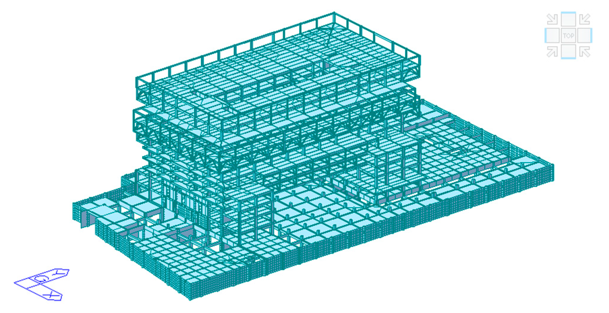
The research and development building of Zhanjiang Bay Laboratory includes the main building in Zone II in the middle and auxiliary buildings in Zone I and Zone III on both sides. The architectural effect is shown in Figure 1. The main building in Zone II adopts a steel frame–core tube shear wall structure system, as shown in Figure 2. There is one basement underground for the underground garage and equipment room, with a height of 6.21 m. The height of the main structure above ground is 46.5 m. There are 10 floors of towers on both sides of the main building, forming a large-span space below the middle 4 floors. The structures above these four floors are connected as a whole. The fourth floor is a large-span and heavy-load-transfer truss with 53.4 m, and there are staggered cantilever structures every two floors between the sixth and tenth floors, with a maximum cantilever height of 8.25 m. “Steel frame core tube shear wall structure system” is a structural system that combines a steel frame structure with a double-steel-sheet concrete composite shear wall structure. The steel frame structure has a small weight and good ductility, which not only reduces the weight of the transfer layer and the above layers but also improves the seismic performance of the building. The rigidity and shear capacity of the double-steel-sheet concrete composite shear wall are very large, so only the core tube shear wall is set at the tower position in the main building structure, which can not only improve the inter-story stiffness ratio but also meet the minimum shear capacity requirements of the code.
Both in the design and construction stages, spatial structure buildings have put forward new requirements for current design norms and construction techniques, which poses new problems for the construction industry [1,2]. For large and complex spatial structural systems, the stress and deformation states of the structure are closely related to the construction scheme, especially the stress state of the large-span and heavy-load-transfer truss, which is very complex. Using different construction sequences or methods during the construction process will have different effects on the stress and deformation of the structure. If the supporting condition of the end of the steel truss is not considered, the force of the end shear wall concrete of the steel truss will be too large, which is unfavorable to earthquake resistance. The construction process is an approximate continuous process in which the structure gradually forms, and the load gradually accumulates. Due to the slow change, the structural stress in the construction process is generally adopted as “slow time-varying mechanics” (i.e., construction mechanics and time-freezing method). When the structure changes slowly with time, the approximate treatment of discrete-time freezing can be used to treat it as a series of time-invariant structures for static or dynamic analysis. In other words, it is necessary to study several of the most unfavorable states in the working process and analyze the strength, stiffness, and stability of the structure in each state without considering the change in the structure [3]. Construction simulation often uses the finite element method to discretize the construction time into several important time points (i.e., construction steps), and at each time point, activate the corresponding component or load, calculate according to the static method, and achieve a gradual loading process [4].
The application of finite element analysis in structural engineering, with special attention to its application in reinforced concrete and steel structures, is exemplified in various studies. For example, Ahad investigated the parallel micro-element system (PMES) on the local bond stress–slip (LBSS) relationship at the steel bar–UHPC interface subjected to monotonic loading [5]. Amini Pishro A. et al. adopted the multiple linear regression (MLR) method to give the LBS equation of reinforced UHPC structural members [6]. Serpieri R. et al. proposed a thermodynamic-based cohesive zone model based on the damage–friction evolution of the steel bar–concrete interface [7]. Santhakumar et al. presented numerical research on non-retrofitted and retrofitted RC beams exposed to combined bending and torsion utilizing the finite element method [8]. Ahad et al. used ABAQUS to conduct finite element analysis for increasing the orientation of different FRP-reinforced and unreinforced concrete beams [9].
In this paper, finite element simulation is carried out on the construction process of a variety of large-span and heavy-load-transfer trusses. According to the simulation calculation results, comparison and selection of construction schemes are carried out to analyze their stress characteristics, and the best construction scheme is selected. Elastic connection is followed by rigid joint construction, and the large-span and heavy-load-transfer trusses are hinged with the core barrel shear wall first. It can improve the stress state of the core barrel shear wall and transfer truss during construction, make the structure more reasonable, greatly increase the overall safety of the structure, and provide a reference for the subsequent construction of similar projects.
2. Comparison and Selection of Multiple Construction Schemes for Transfer Truss
2.1. Design of Large-Span and Heavy-Load-Transfer Truss
Due to the existence of a through space structure with a span of 53.4 m on the first to third floors above ground of the main building in Zone II, the large-span and heavy-load-transfer truss is arranged on the fourth floor above ground, bearing the total weight of up to 17,000 tons from the steel frame and cantilever truss structure of the upper floors.
During the construction phase, as the number of floors increases, the load applied to the heavy-load-transfer truss will increase, and the self-weight of the floors will generate bending moments and shear forces, transferring to the shear walls. To ensure structural safety against progressive collapse, if the elastic connection method is adopted, the treatment method between the connection body and the main building is complex, requiring a large number of supports, adversely affecting the architectural facade effect, curtain wall treatment, and building functionality. Considering these factors, the large-span and heavy-load-transfer truss is selected to be rigidly connected to the shear walls of the core tube of the two towers at both ends.
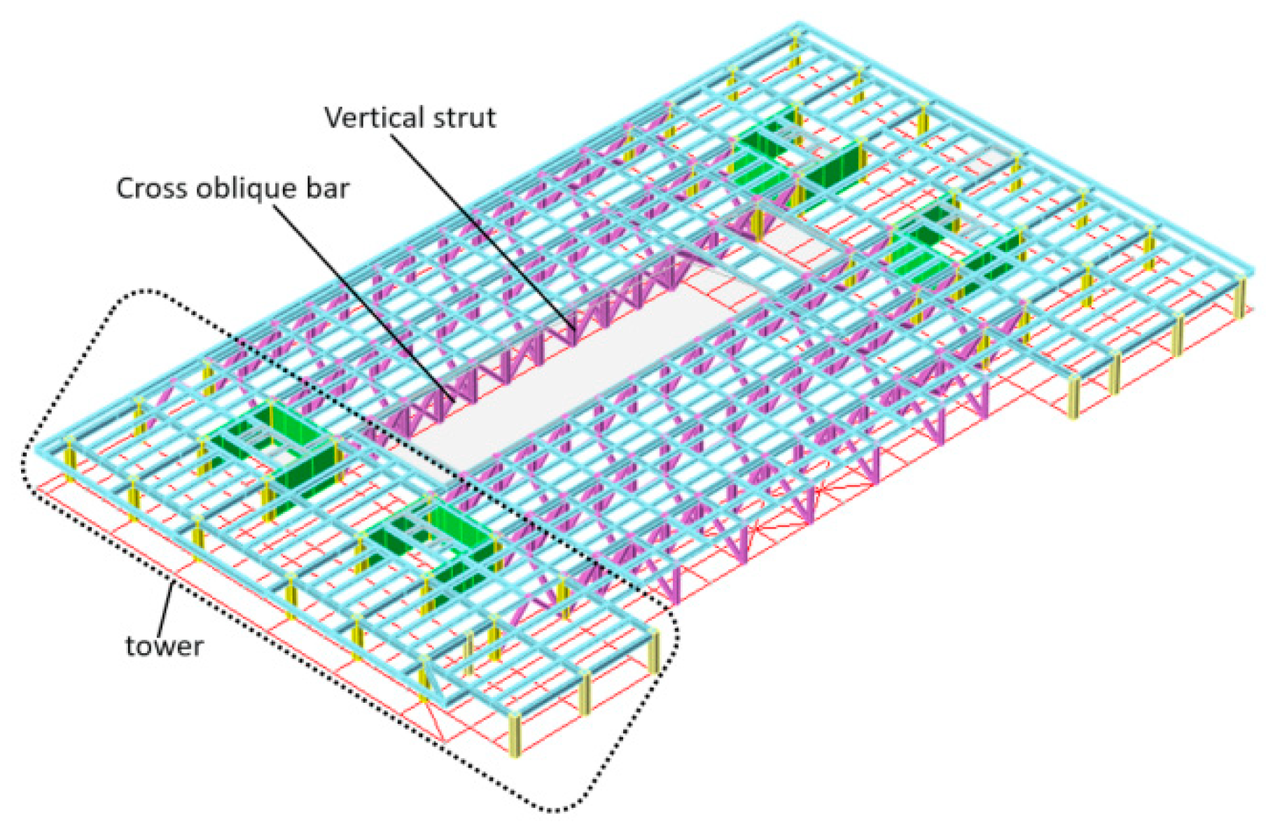
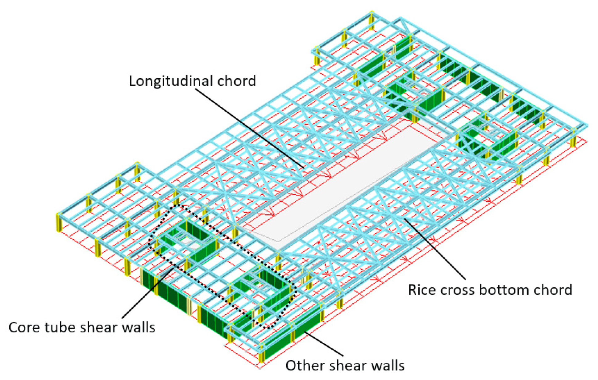
The 53.4 m large-span and heavy-load-transfer truss adopts welded box-shaped section chord and web members, and its vertical web members are set at the corresponding positions of the upper frame columns. The corresponding axis column network is also equipped with trusses of the same height in the vertical truss direction for tension. The tensioning truss chords and web members also use welded box sections, providing support outside the plane of the large-span transfer truss and enhancing the stiffness and integrity of the large-span transfer truss, as shown in Figure 3. The lower chord of the large-span and heavy-load-transfer truss is equipped with a meter-shaped cross brace, as shown in Figure 4. This brace increases the planar stiffness of the transfer truss and improves the overall spatial stress performance of the truss, and the meter-shaped cross brace members use H-shaped steel with a cross-sectional area greater than the longitudinal chord. Therefore, the meter-shaped cross brace will yield after the longitudinal chord and will not yield under small earthquakes, bearing the main seismic load under medium and large earthquakes.
The large-span and heavy-load-transfer truss bears the primary vertical and horizontal loads, acting as the main load-bearing component of the structure, and also plays a role in strengthening structural stiffness and controlling truss deflection. The core tube shear walls of the towers extend up to the tenth floor above ground, while other shear walls extend to the third floor above ground. The core tube shear walls are constructed with a steel-plate composite shear wall structure, where concrete is poured between double-layer steel plates. The steel-plate composite shear wall provides significant lateral stiffness to the entire structure and serves as the main structure supporting the truss structure. The core tube shear walls are the primary lateral-force-resisting elements of this structure [10]. By controlling the construction process and taking full advantage of the excellent load-bearing characteristics of the large-span heavy-load-transfer truss, more load is directed to it, thereby adjusting the forces on the core shear walls and reducing the load on them, resulting in a more rational load distribution throughout the entire structural system [11].
2.2. Simplified Model of Construction Scheme
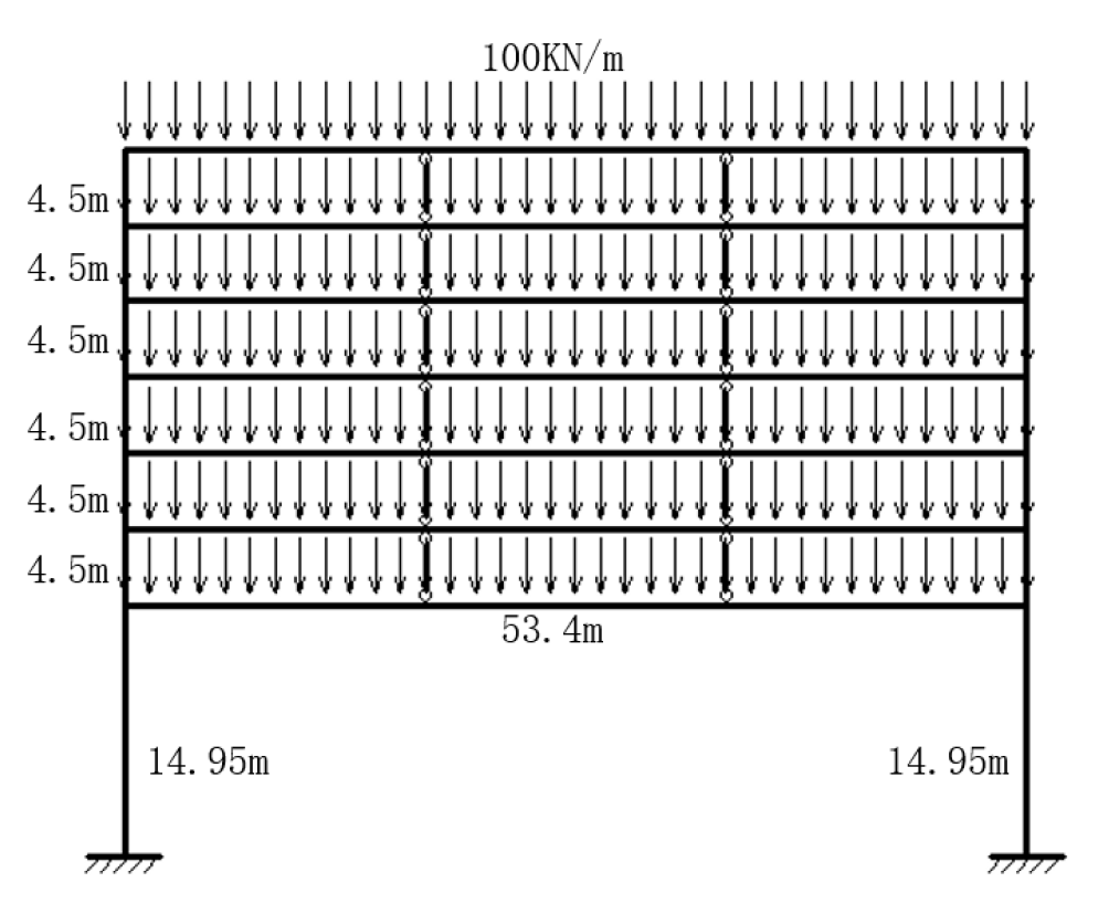
In order to investigate the load-transfer mechanism of the large-span and heavy-load-transfer truss and verify the influence of the construction and installation process on the structural mechanics performance, a single simplified model is selected for comparison and verification. Assuming that the self-weight of each floor is 100 kN/m, the main building structure in Zone II is simplified and analyzed by using the following scheme:
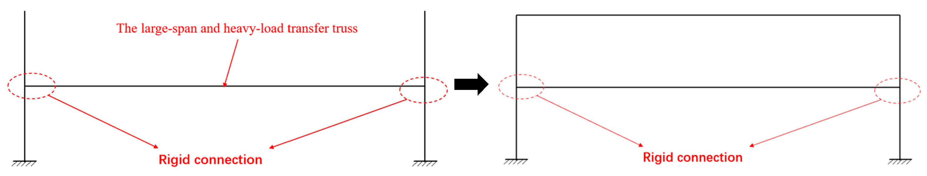
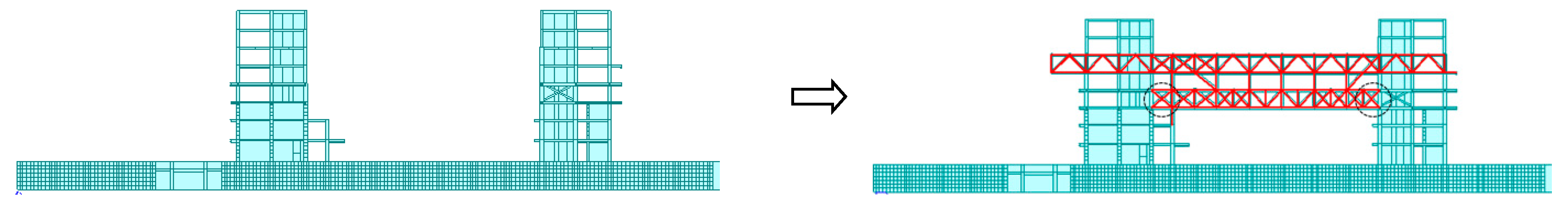
Scheme 1, shown in Figure 5, illustrates the rigid connection construction scheme. After the construction of the basement and the towers on both sides is completed, the fourth-floor large-span and heavy-load-transfer truss is directly rigidly connected to the towers on both sides. Then, the support at the bottom of the large-span and heavy-load-transfer truss is removed. Subsequently, construction is completed layer by layer upward, and the large-span and heavy-load-transfer truss and the side towers remain in a rigidly connected state. The bending moment generated by the construction load on the large-span and heavy-load-transfer truss can be transmitted to the core tube shear wall of the tower. The simplified model is shown in Figure 6.
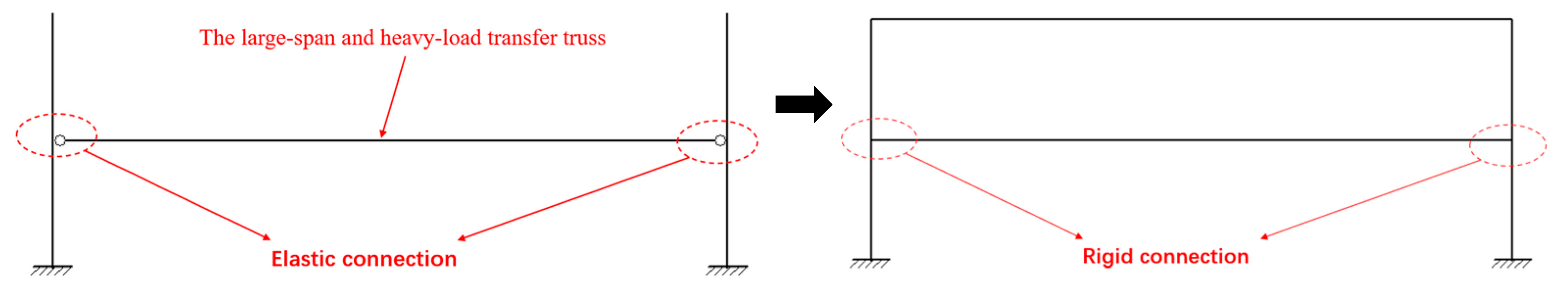
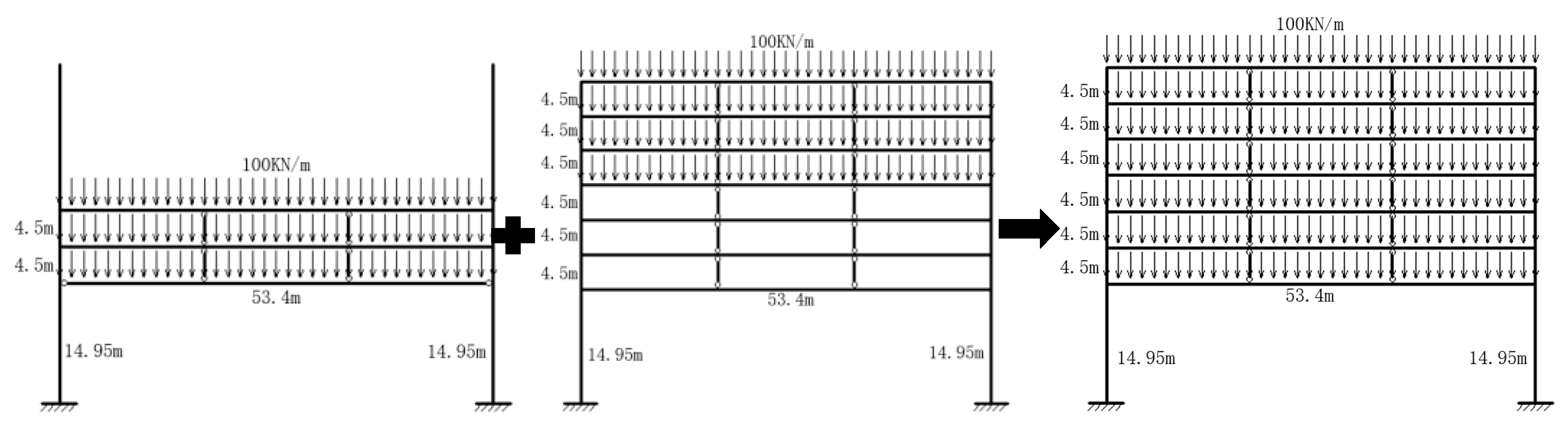
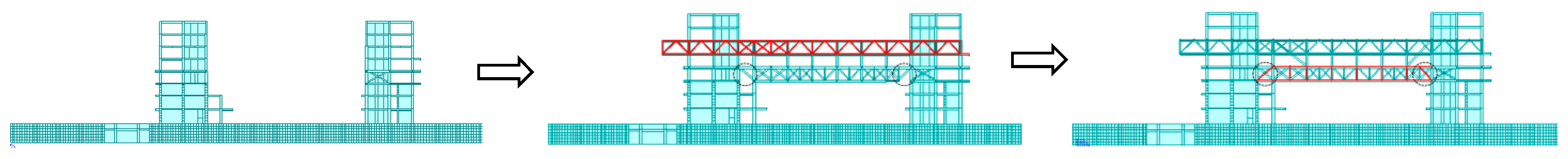
Scheme 2, shown in Figure 7, illustrates the first elastic connection and then the rigid connection construction scheme. Taking the first three floors of the elastic connection construction scheme as an example, the large-span and heavy-load-transfer truss is first elastically connected to the side tower through the upper chord and diagonal web members and then is constructed upwards to the sixth floor above the ground. After the large diagonal tie rod makes the transfer truss and the above two floors form a whole, the lower chord rod of the large-span and heavy-load-transfer truss and another diagonal belly rod are connected, completing the rigid connection between the heavy-load truss and the tower. Continue the construction of the seventh floor, and remove the support at the bottom of the large-span and heavy-load-transfer truss after the completion of the construction of the seventh floor large diagonal tie rod. Then, the construction is completed layer by layer. The superposition principle is used to simplify the construction process, and the simplified model is shown in Figure 8.
From Figure 9, compared to Scheme 1, Scheme 2 shows that after the overall construction is completed, the maximum bending moment at the mid-span of the first two floors of the elastic connection truss increases significantly, and the maximum shear force at the shear wall also increases, which is not recommended to use.
For the construction schemes of elastic connection on the first three floors and elastic connection on the first four floors, although the maximum bending moment at the mid-span of the truss increases slightly, the maximum bending moment and maximum shear force at the truss ends and at the shear walls are significantly reduced, and these can be adopted. In order to select the optimal construction scheme, a simplified simulation is performed after the first elastic connection construction is completed for the three construction options under Scheme 2.
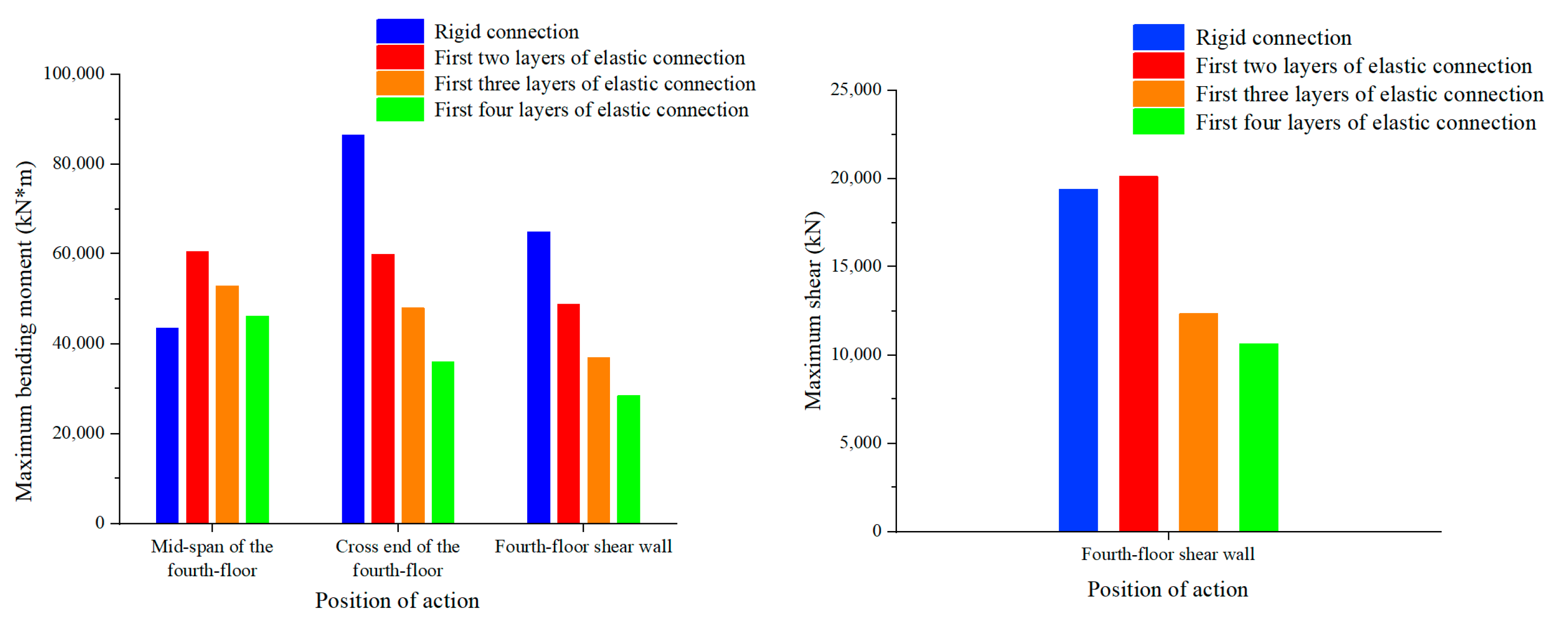
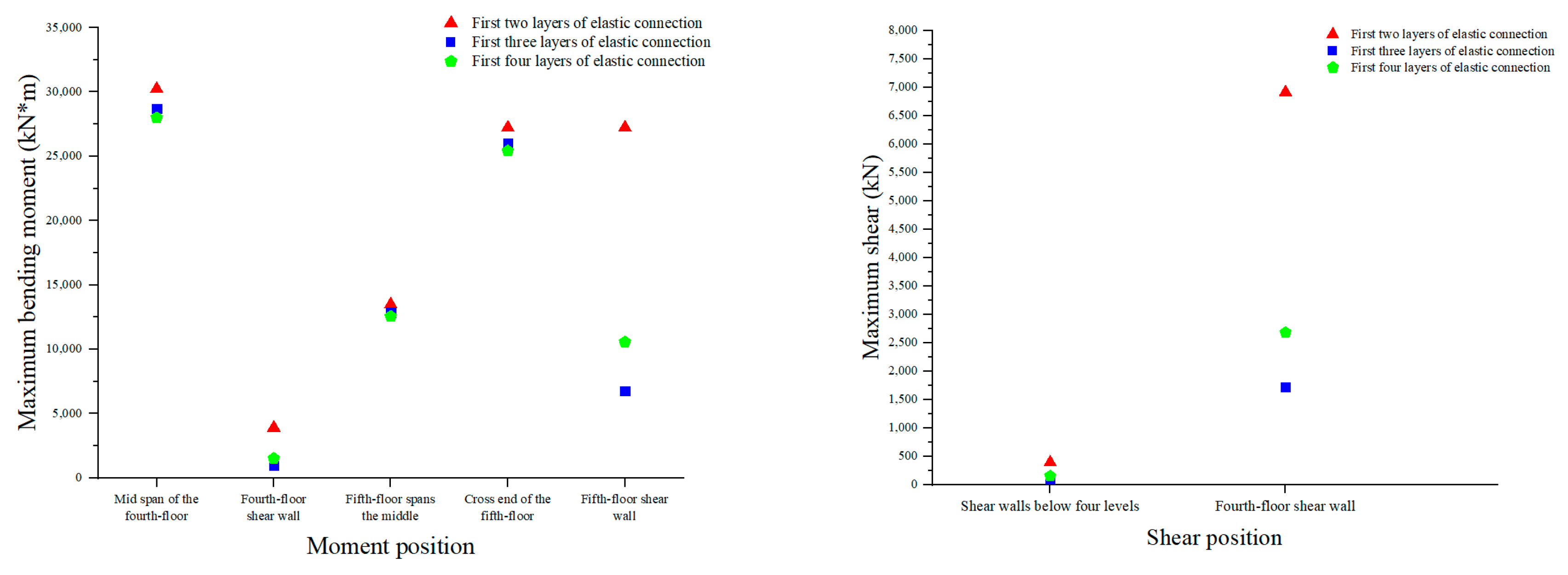
As can be seen from Figure 10, after the construction of the first elastic connection part in Scheme 2 is completed, the simplified model of the first two layers, the first three layers, or the first four layers is used for data analysis. In this model, the fourth-floor large-span and heavy-load-transfer truss is elastically connected to the core tube shear wall, so the bending moment value at the end of the fourth-floor truss is zero. The maximum bending moment and maximum shear force at the shear wall of the first two layers of elastic connection are much greater than the other two schemes, being four times that of the first three layers of elastic connection and twice that of the first four layers of elastic connection. Therefore, the construction scheme of the first two layers of elastic connection is infeasible. Then, a comparative analysis is conducted between the elastic connection schemes for the first three layers and the first four layers, where the maximum bending moment at the mid-span and end-span of the fourth and fifth floors is not significantly different, with only 2.5%. Compared to the first three layers’ elastic connection scheme, the maximum bending moment at the shear wall for the first four layers of the elastic connection increased by 56.45% on the fourth floor and 56.40% on the fifth floor. Simultaneously, the maximum shear force on the fourth floor and below increased by 56.41%. Based on Table 1, it can be seen that the maximum bending moment and shear force of the first four layers of elastic connection have decreased compared with that of the first three layers after the overall construction is completed. However, considering the internal force changes after the construction of the first elastic connection in the early stage, Scheme 2 should choose to use the construction scheme of the first three layers of the elastic connection.
To sum up, after comparing and analyzing the overall construction completion of Scheme 1 and Scheme 2, the maximum bending moment at the mid-span of the large-span and heavy-load-transfer truss increases by 21.71%. However, the maximum bending moment of the end-span of the transfer truss is reduced by 44.59%, while the maximum bending moment and the maximum shear force of the core tube shear wall are reduced by 44.19% and 36.27%, respectively. The comparison results show that both schemes have the same structural stress pattern, with the maximum internal forces occurring at the nodes of the large-span and heavy-load-transfer truss and the core shear wall and the maximum bending moment occurring at the end-span of the fourth-floor large-span and heavy-load-transfer truss. For the core shear wall, the maximum bending moment and maximum shear force both appear at the connection of the fourth-floor large-span and heavy-load-transfer truss and the shear wall. However, the maximum bending moment and maximum shear force generated by Scheme 2 are far smaller than those in Scheme 1, so Scheme 2 is more likely to meet the deflection requirements of the heavy-load-transfer truss, ensuring that the structure has more sufficient safety redundancy and more reasonable stress for the structure itself.
2.3. Single Model of Construction Scheme
The bottom of a single model is rigidly connected, and without external support, the calculation results of the single model tend to be conservative when the stiffness of the floor is completely degraded [12]. In order to obtain the optimal stress state of the core tube shear wall and the large-span and heavy-load-transfer truss, both construction schemes, Scheme 1 and Scheme 2, are simulated separately through Midas.
During the construction phase, the load is taken as one time the self-weight, and the usage stage load is taken as 1.0 times the dead load + 0.5 times the live load. The construction process did not consider the stiffness of the floor, and the floor’s self-weight and load are transmitted to the surrounding beam walls. Both schemes are evaluated using the single model to obtain the internal force results of the core shear wall during the construction process.
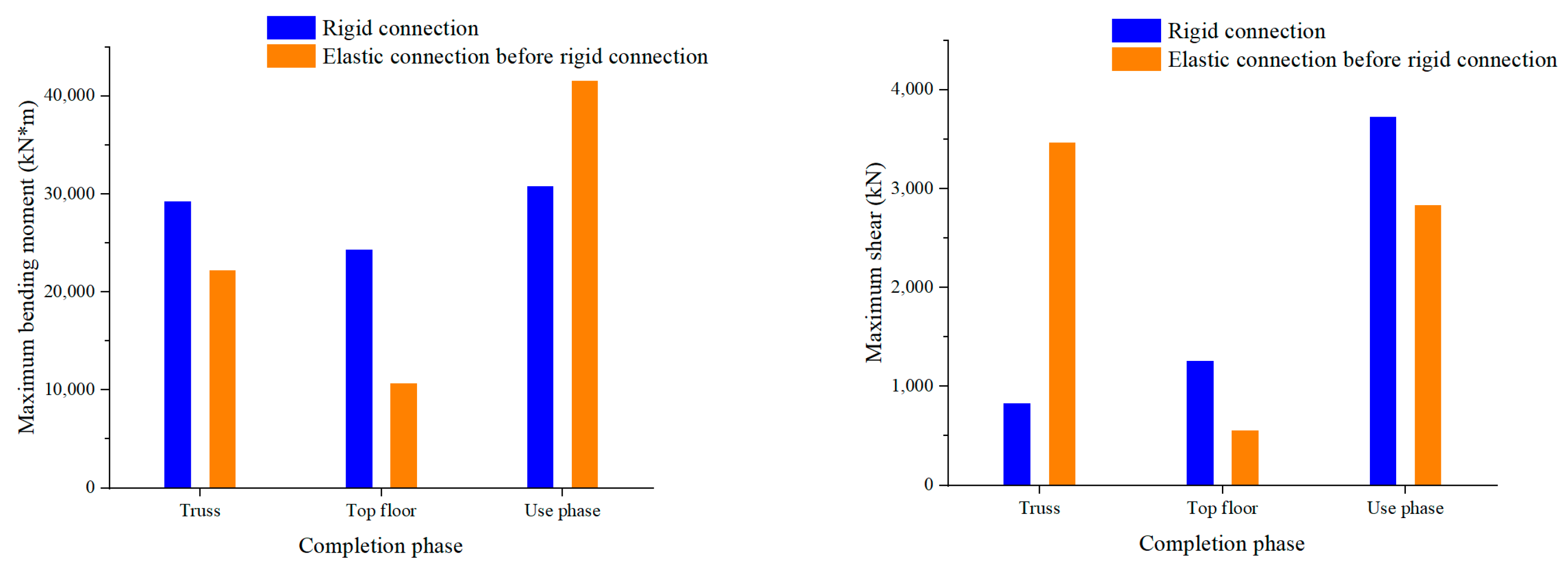
From Figure 11, it can be seen that the bending moment and shear force changes in the shear walls at different construction stages are very obvious for both construction schemes of single-span structures. Compared with the rigid connection construction of Scheme 1, when the fourth-floor large-span and heavy-load-transfer truss is completed in Scheme 2, the maximum bending moment of the core tube shear wall is 22,260.6 kN·m, which is reduced by 24.16%. At this time, the large-span and heavy-load-transfer truss in Scheme 2 is elastically connected to the core tube shear wall, so the maximum shear force of the core barrel shear wall is larger, which is 3474.26 kN, increased by 3.15 times. When the top floor construction is completed, the connection method between the fourth-floor large-span and heavy-load-transfer truss and the core tube shear wall has been converted to a rigid connection. Under the action of self-weight, the maximum bending moment of the overall shear wall is 10,773.7 kN·m, a decrease of 55.79%, and the maximum shear force is 562.16 kN, a decrease of 55.51%. In the use stage after the completion of construction, when 1.0 dead load +0.5 live load is applied, the maximum bending moment of the overall shear wall is 41,640.58 kN·m, which increases by 34.99%, but the maximum shear is 2842.17 kN, which decreases by −23.79%.
In summary, when the overall construction is completed, the maximum bending moment and maximum shear force of the single model constructed by the first elastic connection and then rigid connection in Scheme 2 are smaller than those in Scheme 1 rigid connection construction. This observation indicates that the overall structure possesses favorable mechanical performance and a high level of safety.
2.4. Construction Scheme 3D Model
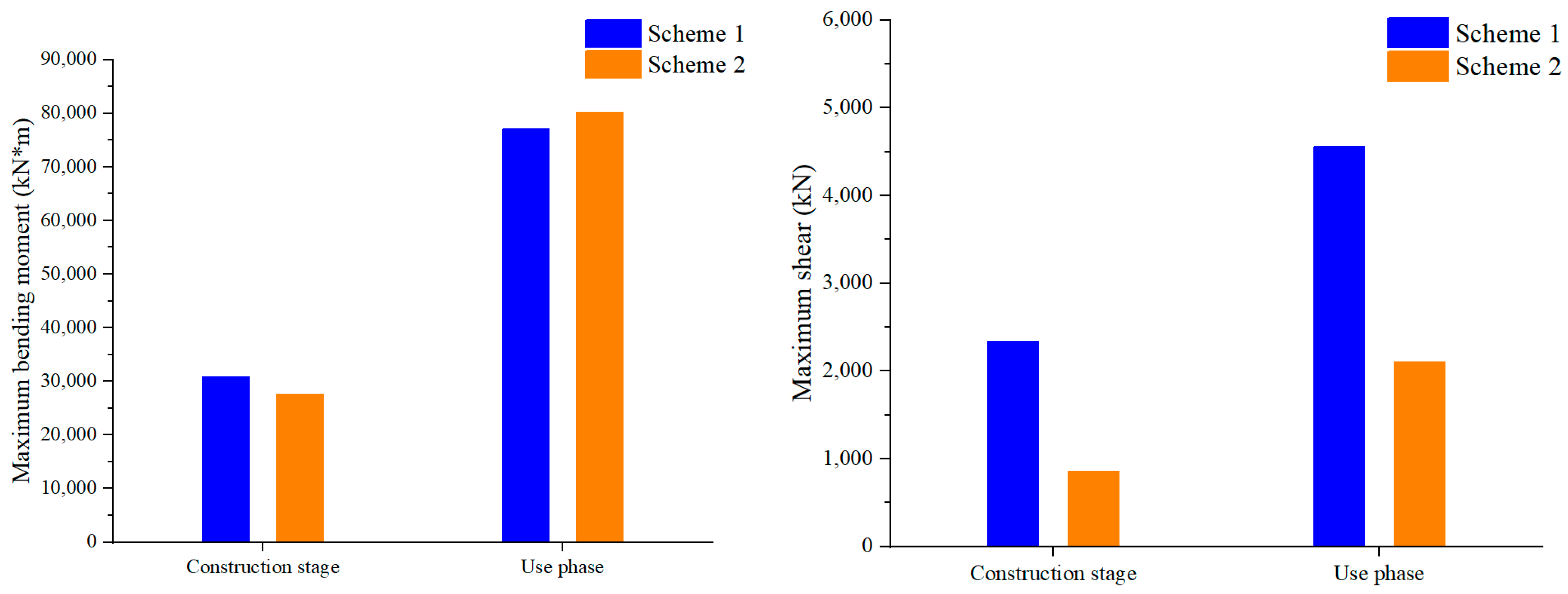
As depicted in Figure 12 and Figure 13, the critical nodes of the 3D models for both schemes are selected for calculation, resulting in the determination of the bending moment and shear force values of the core tube shear wall under different construction schemes, as illustrated in Figure 14.
Upon comparing the structural forces under both different construction schemes, it becomes evident that during the construction stage, after completion of the top floor construction, Scheme 2 exhibits a reduction of 10.47% in the maximum bending moment and a significant decrease of 63.37% in the maximum shear force, in comparison to Scheme 1. However, during the use stage, when 1.0 times the dead load + 0.5 times the live load is applied after the construction is completed, Scheme 2 experiences a slight increase of 4.13% in the maximum bending moment. Nevertheless, the maximum shear force still demonstrates a notable decrease of 53.84% when compared to Scheme 1. These findings indicate that Scheme 2 offers improved mechanical performance and enhanced safety during the overall construction process.
Upon comparing the 3D model with the single model, it is observed that the changes in bending moment and shear force of the shear wall are similar. However, due to the absence of external support in the single model, the proportion of difference in the maximum bending moment undergoes more significant fluctuations, while the proportion of difference in the maximum shear force exhibits clearer variations in the 3D model. The proportion of the maximum bending moment increase generated by Scheme 2 in the 3D model is significantly smaller compared to that in a single model. Both different construction schemes are adopted, and the difference in maximum bending moment borne by the shear wall is minimal. However, the difference in shear force generated by the couple is very obvious. During the construction process of the main structure in Scheme 2, the bending moment and shear force of the shear wall are reduced to a certain extent, making the structural stress more reasonable and the safety redundancy higher.
In summary, through multi-dimensional internal force analysis of simplified models, single models, and 3D models of both schemes, the final choice is to adopt Scheme 2, which involves the first elastic connection and then the rigid connection. In this scheme, the large-span and heavy-load-transfer truss is initially elastically connected to the core tube shear wall, and the shear wall of the core tube is mainly subjected to the vertical pressure from the superstructure. After the completion of the construction of six floors above ground, the large-span and heavy-load-transfer truss is then rigidly connected to the shear wall. At this point, the core tube shear wall starts to bear the bending moment transmitted by the large-span and heavy-load-transfer truss. As a result, after the structural construction is completed, the bending moment and shear force of the core tube shear wall are smaller than those of the shear wall in Scheme 1, making it easier to meet the design requirements of “strong columns and weak beams.” This improvement in the stress state of the core tube shear wall and transfer truss leads to a more rational distribution of structural stress and significantly enhances the overall safety of the structure.
3. Simulation Calculation Based on the Entire Construction Process
3.1. Finite Element Theory during Construction Stage
According to the comparison and research of Scheme 1 and Scheme 2 in the above section, the construction scheme of Scheme 2 with the first elastic connection and then rigid connection is determined to be the optimal construction scheme. With this decision in mind, the entire process of Scheme 2 is simulated and analyzed to examine whether the variations in stress and deflection during the entire construction process align with the requirements specified in the design specifications.
Assembling an incomplete structure into a complete system in stages is a common method in spatial structure construction. Examples of such methods include the unit assembly method, the mobile support method, the sliding method, etc. Accurate structural design calculations during the construction phase of a structure should be based on the actual construction process of the structure [13]. Assuming that a structure is divided into n stages of construction, the basic finite element equations and internal force calculation formulas for each stage of non-integral structure construction are as follows:
Construction Phase 1
1K1U1 = P1 F1 = k1B1U1
Construction Phase II
(2K1 + 2K2)U2 = P2 F2 = k2B2U2
Construction Phase n
(nK1 + nK2 + … + nKn)Un = Pn Fn = knBnUn
In the nth stage of construction, the variables are represented as follows:
- nKi: The total stiffness matrix of the ith unit block structure.
- Ui: The displacement vector of the non-integral structure.
- Pi: The node force vector of the ith unit block structure.
- ki: The element stiffness matrix of the non-integral structural component.
- Bi: The element number matrix of the non-integral structural component.
- Fi: The element internal force vector of the non-integral structural component.
During the analysis and simulation of Scheme 2, these variables play crucial roles in understanding the structural behavior and internal forces at different stages of construction. The utilization of these matrices and vectors allows for a comprehensive evaluation of stress and deflection variations, aiding in the assessment of the structure’s stability and compliance with specified requirements. With these variables, engineers can make informed decisions and implement necessary adjustments to ensure the overall structural integrity and safety of the non-integral structure throughout its construction process.
Assuming the structure is in the linear elastic stage, the final displacement and internal force of the structure can be linearly superimposed as follows:
The superposition principle can be used to calculate the components when they are in the linear elastic deformation stage in the construction stage, which greatly reduces the calculation time and ensures the overall structural integrity and safety of the non-integral structure during the whole construction process.
3.2. Construction Process Simulation
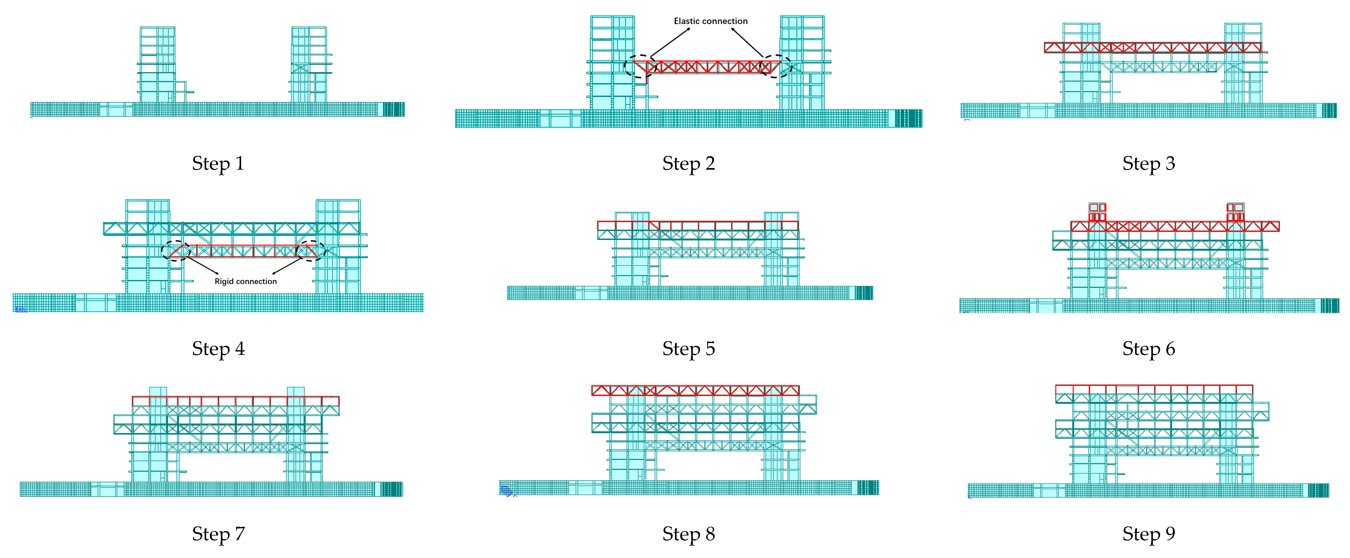
The construction scheme that adopts Scheme 2 of the first elastic connection and then rigid connection introduces a discontinuity between the large-span and vertical components in the structure. Consequently, the timing of support removal during the construction stage significantly influences the stress state of the large-span and heavy-load-transfer truss. To address this, the principle of dividing the construction steps is based on using the transfer truss and temporary support as boundaries. The timing of support removal during the construction phase determines the stress state of the transfer trusses of the transfer layer. When the large-span and heavy-load-transfer trusses become rigid connections, the stress will increase when the support is removed, and the bending moment at the end of the trusses will also occur due to the change in the stress mode of the trusses. The parts without the transfer truss and temporary support are divided into one construction step, while the model is separated into different construction steps layer by layer at the transfer truss and temporary support. Each division is considered as a time period during model calculation. During the construction phase, the online elastic deformation phase at the component can be simulated using the superposition principle to replicate the traditional construction scheme involving layer-by-layer construction and layer-by-layer formwork removal. Midas Gen is utilized to achieve this simulation, and the model diagram of each construction step under Scheme 2 construction is depicted in Figure 15.
3.3. Analysis of Construction Simulation Results
Based on the actual full construction process of the project, and taking into consideration the construction schemes provided by the design and construction units, the load during the construction phase is taken as one times the self-weight, with no consideration given to the floor stiffness. The floor stiffness is adjusted to 0.01 times the actual forming stiffness, and the load during the use stage after construction is taken as 1.0 times the dead load + 0.5 times the live load. The simulation calculation results of the entire construction process in Scheme 2 are shown in Table 1.
From Table 1, it can be seen that the maximum vertical deformation in the mid-span of the large-span structure is 35.66 mm, the maximum stress is 74.11 Mpa when the bending moment of the truss floor is released, and the upper diagonal tie rod is located on the two floors. Upon reaching the top floor during construction, the large-span structure exhibits a maximum vertical deformation of 44.03 mm and a maximum stress of 93.7 MPa. Subsequently, when the main construction is completed, and 1.0 times the dead load + 0.5 times the live load is applied, the maximum stress of the structure during the construction process remains in a tensile state, reaching a maximum stress of 209.63 MPa, which meets the stress requirements. Additionally, the maximum vertical deformation in the mid-span of the transfer floor reaches 74.61 mm, resulting in a deflection-to-span ratio of 1/716, which satisfies the allowable deflection value specified as 1/400 in the regulations.
3.4. Results and Discussion
Based on the simulation and verification through layer-by-layer construction, the results indicate that the deflection of the large-span and heavy-load-transfer truss meets the specifications’ requirements during the construction process, and the stress of the steel structure components remains in the elastic stage. In the process of structural construction, the improvement in the stress state of the core tube shear wall and the transfer truss makes the structural stress distribution more reasonable and significantly improves the overall safety of the structure. To ensure structural stability, deformation and stress monitoring should be conducted on the large-span and heavy-load-transfer truss and the connecting parts of the two towers on both sides. Ensure safety during construction. It is crucial to control the deformation at each construction stage to ensure it does not exceed the calculated value. Specifically, careful attention should be given to the stress state of the upper and lower chords and diagonal web members at the mid-span, as well as the connecting parts at both ends of the large-span and heavy-load-transfer truss, to prevent any exceeding of the calculated value that might lead to local component instability. To further ensure stability during construction, effective stability control measures must be implemented for the local structures.
4. Conclusions
This article presents an analysis of the stress situation of the core tube shear wall in the Zhanjiang Bay Laboratory R&D Building under both construction and use conditions. Multiple construction schemes are compared and evaluated, and simulations are performed to assess the vertical displacement and stress of the large-span and heavy-load-transfer truss. Based on these analyses, the optimal construction and installation scheme is proposed, leading to the following conclusions:
(1) By simplifying the model to study the force transmission mechanism of the large-span and heavy-load-transfer truss, it is found that both schemes have the same structural stress form. However, the maximum bending moment and maximum shear force generated by the construction of the first elastic connection and then the rigid connection in Scheme 2 are much smaller than those generated by the construction of the rigid connection in Scheme 1.
(2) Through Midas simulation of both construction schemes under a single model and a 3D model, it is found that the bending moment and shear force changes in the shear wall are similar, but the proportion of the difference in the maximum bending moment in the single model changes more significantly, and the proportion of the difference in the maximum shear force in the 3D model changes more clearly. During the construction phase, particularly when the top floor construction is completed, Scheme 2 exhibits smaller maximum bending moment and maximum shear force values compared to Scheme 1. However, after the completion of construction, while the maximum shear force generated by Scheme 2 remains smaller than that of Scheme 1, the maximum bending moment has increased.
(3) By adopting Scheme 2 with the first elastic connection and then rigid connection, the stress state of the core tube shear wall and transfer truss is improved, leading to a more reasonable distribution of structural stress. The bending moment and shear force of the core tube shear wall are smaller than those of the shear wall in Scheme 1, and it is easier to meet the design requirements of “strong columns and weak beams”.
(4) During the construction process, it is essential to conduct deformation and stress monitoring for the large-span and heavy-load-transfer truss and the connecting parts of the two towers on both sides. This monitoring helps to ensure that the deformation at each construction stage remains within the calculated value. Additionally, close attention should be given to the stress state of the upper and lower chords, diagonal web members at the mid-span, and the connecting parts at both ends of the large-span and heavy-load-transfer truss. The stress levels should not exceed the calculated value to prevent any local instability of the components. To maintain structural stability and prevent potential instability, effective measures for stability control must be implemented for the local structures under construction. These measures contribute to the formation of stable and efficient spatial structures, ensuring the overall safety and reliability of the construction process.
5. Possible Directions for Future Studies
The stress state and deformation state of large complex space structures are closely related to the construction scheme. The designer puts forward the final working state of the structure and then requires the construction personnel to determine the construction scheme. In the end, it is difficult to fully meet the design requirements, and there are hidden dangers. Based on this characteristic, the construction scheme should be incorporated into the structural design of the long-span and heavy-duty transfer truss, and the integrated analysis should be carried out. The design should be adjusted according to the construction scheme, and the construction scheme should be optimized. The specific design and construction scheme for specific projects can greatly reduce the safety hazards in the construction process and speed up the project’s progress.
Author Contributions
Writing—original draft, T.L.; software, G.X.; investigation, Z.L.; methodology, G.Q.; methodology, R.G. All authors have read and agreed to the published version of the manuscript.
Funding
This study was supported by the CSSC International Engineering Co., Ltd. Technological Innovation and research and development project (CN) Award Number: 20MT01J and 20MT07J.
Data Availability Statement
The data presented in this study are available in this article.
Conflicts of Interest
Authors Tao Lan, Guangchong Qin, Zexu Li and Ruixiang Gao were employed by the company CSSC International Engineering Co., Ltd. The remaining authors declare that the research was conducted in the absence of any commercial or financial relationships that could be construed as a potential conflict of interest. The authors declare that this study received funding from CSSC International Engineering Co., Ltd. The funder had no role in the design of the study; in the collection, analysis, or interpretation of data, in the writing of the manuscript, or in the decision to publish the results.
References
- Dong, S.; Xing, D.; Zhao, Y. Application and Development of Modern Large Span Space Structures in China. Space Struct. 2012, 18, 3–16. [Google Scholar]
- Dong, S. Development and Prospects of Spatial Structure in China. J. Archit. Struct. 2010, 31, 38–51. [Google Scholar]
- Wang, G. Time varying Structural mechanics. J. Civ. Eng. 2000, 33, 105–108. [Google Scholar]
- Yang, W.; Hong, G.; Wang, M.; Yang, G.; Zhang, G.; Wang, S.; Duan, Y.; Ge, J.; Zhou, W. Simulation analysis of the entire construction process of multi-layer large cantilever steel structures. J. Build. Struct. 2012, 33, 87–94. [Google Scholar]
- Pishro, A.A.; Zhang, Z.; Pishro, M.A.; Xiong, F.; Zhang, L.; Yang, Q.; Matlan, S.J. UHPC-PINN-Parallel Micro Element System for the Local Bond Stress–Slip model subjected to monotonic loading. In Structures; Elsevier: Amsterdam, The Netherlands, 2022; Volume 46, pp. 570–597. [Google Scholar]
- Amini Pishro, A.; Zhang, S.; Huang, D.; Xiong, F.; Li, W.; Yang, Q. Application of artificial neural networks and multiple linear regression on local bond stress equation of UHPC and reinforcing steel bars. Sci. Rep. 2021, 11, 15061. [Google Scholar] [CrossRef] [PubMed]
- Zhang, Z.; Matlan, S.J.; Wang, H.; Amini Pishro, A.; Zhang, L.; Gao, X.; Liang, Z.; Liu, X.; Zhao, P. Geotechnical Evaluation of Loess Modifications as the Sustainable Compacted Soil Liner Material in Solid Waste Landfill. Materials 2022, 15, 4982. [Google Scholar] [CrossRef] [PubMed]
- Santhakumar, R.; Dhanaraj, R.; Chandrasekaran, E. Behavior of Retrofitted Reinforced Concrete Beams under Combined Bending and Torsion: A numerical study. Electron. J. Struct. Eng. 2007, 7, 1–7. [Google Scholar] [CrossRef]
- Amini Pishro, A.; Zhang, S.; Zhang, Z.; Zhao, Y.; Amini Pishro, M.; Zhang, L.; Yang, Q.; Postel, V. Structural Behavior of FRP-Retrofitted RC Beams Under Combined Torsion and Bending. Materials 2022, 15, 3213. [Google Scholar] [CrossRef] [PubMed]
- Lan, T.; Wang, X. Analysis and Application of Double Steel Plate Concrete Composite Shear Wall in the R&D Building of Zhanjiang Bay Laboratory. Buildings, 2023; in press. [Google Scholar]
- He, M.; Qiu, T.; Xiao, C.; Liu, Z.; Tang, J. Analysis of the entire process of steel truss transfer story construction. Low Temp. Build. Technol. 2004, 30–32. [Google Scholar]
- Lan, T.; Li, M. Seismic Design of Large-Span and Heavy-Load Transfer Truss for Zhanjiang Bay R&D Building. Buildings, 2023; in press. [Google Scholar]
- He, Q.; Gao, M.; Zhang, R.; Luo, Y.; Shen, Z. Analysis of the whole construction process of a large-scale steel structure roof system. Struct. Eng. 2005, 81–84. [Google Scholar] [CrossRef]
Figure 1.
Architectural renderings of Zhanjiang Bay Laboratory.

Figure 2.
Steel frame–core tube shear wall structure.

Figure 3.
Heavy-load-transfer truss top string and belly bar.

Figure 4.
Heavy-load-transfer truss lower chord.

Figure 5.
Scheme 1 (rigid connection construction scheme).

Figure 6.
Scheme 1 simplified model.

Figure 7.
Scheme 2 (first elastic connection and then rigid connection construction scheme).

Figure 8.
Scheme 2 simplified model (the first three floors of elastic connection).

Figure 9.
Maximum internal force of simplified models with different schemes.

Figure 10.
The internal diagrams of different numbers of hinged layers in Scheme 2.

Figure 11.
Internal force diagram of shear wall of core tube under different schemes.

Figure 12.
Rigid connection construction process.

Figure 13.
The first elastic connection and then rigid connection construction process.

Figure 14.
Internal forces of core tube shear walls under different construction schemes.

Figure 15.
Scheme 2 Construction Step Model Diagram.


Table 1.
Main Construction Steps and Calculation Results of Scheme 2.
| Construction Steps | Construction Content | Maximum Vertical Displacement (mm) | Ratio of Deflection to Span | Ratio of Deflection to Span (N/mm2) |
|---|---|---|---|---|
| Step 1 | The basement construction is completed, and the towers on both sides are constructed to the eighth floor above ground. | 4.96 | 1/10,766 | 15.64 |
| Step 2 | Establishment of support and completion of elastic connection construction between the fourth-floor transfer truss on the ground and the core tube shear wall. | 22.51 | 1/2372 | 54.76 |
| Step 3 | The construction of the steel frame and cantilever parts in the upper area of the fifth-floor and sixth-floor transfer trusses above ground has been completed. | 34.77 | 1/1536 | 69.16 |
| Step 4 | The construction of the steel frame and cantilever parts in the upper area of the fifth-floor and sixth-floor transfer trusses above ground has been completed, and the large diagonal tie rods on both sides have been installed on the sixth floor. The fourth-floor transfer truss above ground has been converted to a rigid connection with the core tube shear wall. | 35.66 | 1/1497 | 74.11 |
| Step 5 | Install the left large diagonal tie rod to the seventh floor, remove the support, and complete the construction of the seventh-floor frame and cantilever part. | 36.86 | 1/1449 | 79.06 |
| Step 6 | The eighth-floor frame and cantilever section, as well as the core tubes on both sides of the ninth floor and tenth floor, have been constructed layer by layer. | 41.16 | 1/1297 | 84.80 |
| Step 7 | The construction of the ninth-floor frame and cantilever parts has been completed layer by layer. | 42.87 | 1/1246 | 88.86 |
| Step 8 | The construction of the tenth-floor frame and cantilever parts has been completed layer by layer. | 43.73 | 1/1221 | 92.80 |
| Step 9 | The installation of the eleventh-floor frame and the remaining overhanging edge truss has been completed, and the replacement section of the large diagonal tie rod has been replaced. | 44.03 | 1/1213 | 93.73 |
| Use Phase | After the construction of the main structure is completed and the stiffness of the concrete floor slab is formed, the standard value of gravity load is applied. | 74.61 | 1/716 | 209.63 |
In the table, the positive direction of vertical displacement is taken as the vertically upward direction (i.e., the positive direction of the z-axis). The maximum vertical displacement refers to the maximum absolute value of vertical displacement. The structural span corresponding to the deflection-to-span ratio is L = 53,400 mm.
Disclaimer/Publisher’s Note: The statements, opinions and data contained in all publications are solely those of the individual author(s) and contributor(s) and not of MDPI and/or the editor(s). MDPI and/or the editor(s) disclaim responsibility for any injury to people or property resulting from any ideas, methods, instructions or products referred to in the content. |
© 2023 by the authors. Licensee MDPI, Basel, Switzerland. This article is an open access article distributed under the terms and conditions of the Creative Commons Attribution (CC BY) license (https://creativecommons.org/licenses/by/4.0/).
Share and Cite
MDPI and ACS Style
Lan, T.; Xing, G.; Qin, G.; Li, Z.; Gao, R. Comparison and Selection of Multiple Construction Schemes for the Large-Span and Heavy-Load Transfer Truss. Buildings 2023, 13, 3056. https://0-doi-org.brum.beds.ac.uk/10.3390/buildings13123056
AMA Style
Lan T, Xing G, Qin G, Li Z, Gao R. Comparison and Selection of Multiple Construction Schemes for the Large-Span and Heavy-Load Transfer Truss. Buildings. 2023; 13(12):3056. https://0-doi-org.brum.beds.ac.uk/10.3390/buildings13123056
Chicago/Turabian StyleLan, Tao, Guangjie Xing, Guangchong Qin, Zexu Li, and Ruixiang Gao. 2023. "Comparison and Selection of Multiple Construction Schemes for the Large-Span and Heavy-Load Transfer Truss" Buildings 13, no. 12: 3056. https://0-doi-org.brum.beds.ac.uk/10.3390/buildings13123056
Note that from the first issue of 2016, this journal uses article numbers instead of page numbers. See further details here.