Article

Optimal Design of Segment Storage and Hoisting of Precast Segmental Composite Box Girders with Corrugated Steel Webs

1
College of Civil Engineering, Nanjing Tech University, Nanjing 210000, China
2
The State Key Laboratory on Safety and Health of In-Service Long-Span Bridges, Nanjing 211100, China
3
Jiangsu Transportation Research Institute, Nanjing 211100, China
4
Communication Design & Research Institute Co., Ltd. of Jiangxi Prov., Nanchang 330000, China
*
Author to whom correspondence should be addressed.
Submission received: 7 February 2023 / Revised: 12 March 2023 / Accepted: 16 March 2023 / Published: 17 March 2023
(This article belongs to the Special Issue New and Future Progress for Concrete Structures)

Abstract

:
To optimize the segment storage and hoisting plan of precast segmental composite box girders with corrugated steel web bridges, China’s first precast segmental composite girder bridge with corrugated steel webs is taken as the background. The difference between the precast segmental composite box girders with corrugated steel webs and the traditional concrete box girder is proven by numerical simulation. The stress and deformation characteristics of the segmental girder during storage and hoisting are analysed, and reasonable control measures are proposed. The data suggested that compared with ordinary concrete box girders, the smaller torsional stiffness and lateral stiffness of the precast segmental composite box girder with corrugated steel web segments lead to larger roof stress and deformation during the storage and hoisting periods. The number of storage layers of segmental girders should not exceed two, and the four hoisting point scheme should be adopted for hoisting. It is recommended to set one to two channel steel supports of no less than 20 grade steel between the top and bottom plates to avoid excessive deformation of the roof. With the increase in the segment length, the roof deformation and stress increased regardless of the storage period and the hoisting period. If the safety factor needs to be increased, when the segment length is short (1.6 m–3.2 m), increasing the support size is recommended. When the segment length is longer (4.0 m, 4.8 m), increasing the number of supports is recommended.

1. Introduction

In recent years, precast assembly technology has become increasingly used in bridge construction due to its advantages, including fast construction speed, easy quality control, and good environmental performance [1,2,3,4]. Affected by the elastic—plastic deformation caused by concrete shrinkage, creep, and temperature change, the webs of traditional concrete box girders (CBGs) are prone to cracks, and the prestress loss is also large. The joints of concrete box girders constructed through precast assembly technology have a great influence on the shear resistance of girders, and the force transmission is complex [5,6,7,8,9]. In the composite box girders with corrugated steel webs (CBGCSWs), the traditional concrete web is replaced with a thin corrugated steel plate, which greatly reduces the weight of the structure and reduces the prestress loss [10,11,12,13]; additionally, the web is suitable for factory processing. Compared with the shear resistance of the toothed joints of the precast segmental concrete box girders (PS-CBGs), the precast segmental composite box girders with corrugated steel webs (PS-CBGCSWs) mainly rely on the steel web for shear resistance, their joints have less influence on the shear resistance of the main girder, and the force transmission is clear. The construction method used with the precast segmental composite box girders with corrugated steel webs combines segmental prefabrication, composite box girders with corrugated steel webs and external prestressing, which can greatly shorten the construction period, improve the construction quality, reduce the environmental impact, and have good economic and aesthetic effects [14,15].
The first highway bridge to use corrugated webs was the Cognac Bridge, which was built in France in 1986 as an experimental bridge. These French bridges served as inspiration for a number of similar structures in Japan, which were built in the 1990s, beginning with the Shinkai Bridge in 1993, followed by the Matsunoki No. 7 Bridge in 1995, and the Hondani Bridge in 1997. Other countries subsequently began construction of corrugated steel web bridges [16]. At present, many scholars have performed many research studies on composite box girders with corrugated steel webs [17,18,19,20,21,22] or precast segmental concrete box girders [23,24], but there are very few studies on precast segmental composite box girders with corrugated steel webs. Chen et al. [17] studied the flexural properties of composite box girders with corrugated steel webs through experiments and numerical analysis, and established a theoretical model for calculating the bending moment of composite girders under ultimate load. Shi et al. [18] studied the flexural vibration behaviour of a variable cross-section box-girder bridge with corrugated steel webs and provided detailed equations for analysing the dynamic characteristics of simply supported girders. Zhu et al. [19] developed a simplified method for calculating the torsional capacity of composite box girders with corrugated steel webs repaired using carbon fibre-reinforced polymers. Zhang et al. [20,21,22] studied the behaviour of composite box girders with corrugated steel webs under pure torsion, analysed the influence of the related geometric factors, such as the ratio of the width to the height, ratio of the width to the span length, and ratio of the width to the thickness of the slab, and developed prediction formulas for stiffness, crack torque, and ultimate torque. Zhu et al. [23] studied the long-term performance of the precast segmental construction technology built by ultra-high-performance concrete wet joints. Do et al. [24] studied the early-age thermal behaviour of segmental concrete box girders using finite element (FE) analysis, established an FE segmental box-girder diaphragm model, and found that when high-strength concrete is used, regardless of the volume-to-surface area ratio, the segmental box-girder diaphragms are considered mass concrete, and measures should be taken to prevent accidental thermal cracking. H. Ahmed et al. [25,26,27] systematically studied the effect of joints that represent locations of discontinuity on the overall structural performance of segmental bridges. The study results showed that the shear capacity of epoxied joints was consistently higher than that of dry joints by 25–28%, but the failure of epoxied joints was sudden and brittle. If the confining pressure is increased to 4.5 MPa and the number of shear keys is increased from 6 to 10, the elastic stiffness and plastic ductility of the segmental bridge can be greatly improved, and the brittle behaviour of the epoxied joints can be changed to a gradual strength degenerate mode. Zhang et al. [28] designed two steel-concrete composite box girders with corrugated webs and steel bottom flanges, and conducted experimental studies on them. They deeply analysed the test results of the failure mode, mechanical properties, bearing capacity, deformation capacity, and the strain and stress evolution of each component. It was found that during the prestressing process of composite beams, the prestress of the concrete floor could be effectively transferred to the concrete roof through the coordinated deformation of the web, while the sheer force of the section was mainly transferred by the corrugated steel web. Z.C. Zhang et al. [29] focused on the large difference between the longitudinal and transverse stiffness of corrugated steel webs. They assumed a zig-zag displacement to describe the deformation along the beam thickness, along with a layer-wise parabolic distribution of the transverse shear stress. Wang et al. [30] studied the interaction between local buckling, global buckling, and interactive buckling stresses in corrugated steel webs. They revealed the influence of important parameters on the buckling stresses.
For composite box girders with corrugated steel webs, the research mainly focuses on the flexural performance [31], shear performance [32,33,34,35] and torsional performance [36,37,38,39]. For precast segmental concrete box girders, the research focuses on joints that represent points of discontinuity. As the webs of the box girders assembled by precast segments are transformed from concrete to corrugated steel webs, the joints have little effect on the overall structural performance of the segmental bridge. However, the transverse bending stiffness of the segmental box girders with steel corrugated webs is weaker than that of bridge girders with concrete webs because the steel corrugated webs cannot provide strong rotational end restraints for the top concrete flange [40,41]. Therefore, stress concentration or large deformation is prone to occur in the process of segment girder storage and hoisting, which affects the linear progress of precast segmental box girders and brings great difficulties to the assembly of composite box girders with corrugated steel webs and web welding. At present, there is no research on the storage and hoisting of precast segmental composite box girders with corrugated steel webs. Therefore, this paper takes the Nanjing No. 5 Bridge approach bridge (Lixin Road flyover bridge) as the case study, and the stress and deformation performance of the precast segmental composite box girders with corrugated steel web bridges are analysed during storage and hoisting.

2. Practical Bridge Project

As the first bridge with precast segmental composite box girders with corrugated steel webs in China, the Nanjing Fifth Yangtze River Approach Bridge combines the advantages of segmental precasting, composite box girders with corrugated steel webs, and external prestressing, as shown in Figure 1a,b. It overcomes the shortcomings of traditional concrete box girders, such as a large prestress loss, large influence of joints on the shear resistance of the main girder, and easy cracking of the concrete web, effectively reducing the self-weight of the bridge and greatly shortening the construction period. This is the first study to combine segmental precast assembly technology with novel composite box girders with corrugated steel webs to promote the development of composite structure bridges and inject new strong vitality into segmental precast bridges. The span of the Lixin Road flyover bridge is 31 + 46 + 31 m, the section is in the form of a single box and single chamber composite box girders with corrugated steel webs, and the girder is constructed using precast segments. The midspan façade layout is shown in Figure 1c. The bridge has a total of 74 precast segments. The longest precast segment is 3.2 m. The standard section layout is shown in Figure 1d. The standard box girder roof width is 14.9 m, and the girder height is 2.6 m. The corrugated steel web and the concrete roof use double-hole steel plate connectors, and the concrete bottom plate adopts embedded connectors.

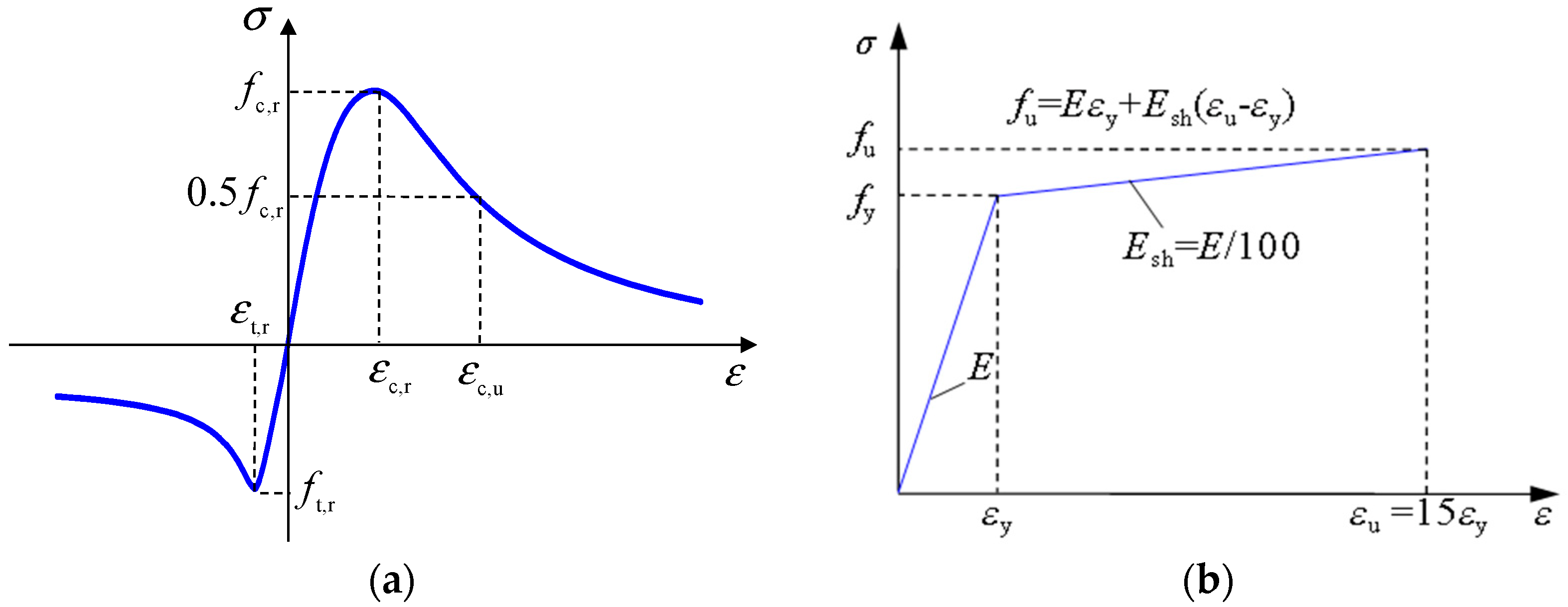
3. Finite Element Model
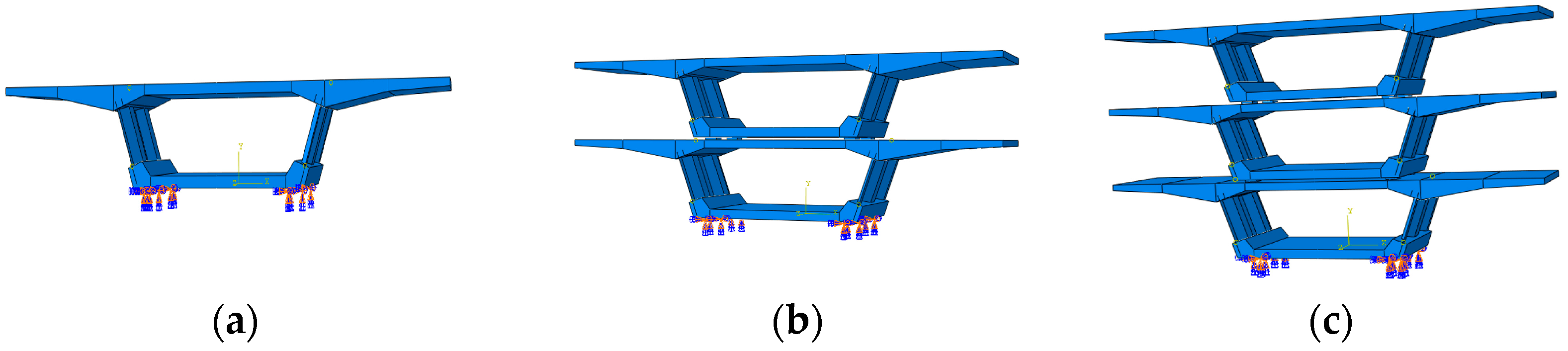
Abaqus was used to build a refined finite element model of a typical segment of the Lixin Road flyover bridge (Figure 2) to reveal the stress and deformation of a single segment of a precast segmental composite box girder with corrugated steel webs during storage and hoisting, and stress and deformation control measures were proposed. In the model, the C3D8R eight-node linear hexahedron element in Abaqus is used to simulate the concrete. This element has several advantages, including higher accuracy, good element distortion control, efficient computation, and wide applicability. The T3D2 two-node linear three-dimensional truss element is used to simulate the steel bars and prestressed tendons. This element is useful for modelling slender structures that mainly carry axial loads, and its simplicity and computational efficiency make it a popular choice in engineering analysis. The S4R four-node surface shell element is used to simulate the corrugated steel webs and upper flange plate. This element is specifically designed for modelling thin-walled structures, such as plates, shells, and composite laminates. The S4R element assumes that the strain and displacement fields vary linearly across the thickness of the element, and in-plane deformation is represented by nodal displacements. The S4R element is based on a four-node quadrilateral flat element with reduced integration. The bifold line constitutive model is adopted for the steel plate and steel bar, and the elastoplastic model is adopted for the concrete, as shown in Figure 3. Typically, the elastic behaviour of the material is described using Hooke’s law, while more complex nonlinear models, such as the von Mises, Drucker—Prager, and Mohr—Coulomb yield criteria are used to describe the plastic behaviour. These models consider factors, such as strength, plastic strain, and stress, and can be parameterized for different materials. In conclusion, the elastoplastic model in Abaqus is effective for simulating the elastic and plastic behaviour of the materials. Table 1 displays the parameters of each material. fc,r and ft,r are the unidirectional compressive and tensile strengths of concrete, respectively. εc,r and εt,r are the strains corresponding to fc,r and ft,r, respectively. Ec is the elastic modulus of concrete. The elastic modulus of the plastic stage is 1/100 of the elastic stage, fy is the yield strength of the steel, and εy is the yield strain of the steel. Since the interaction and loading methods during storage and hoisting are slightly different for different girders, this subsection focuses on the interaction and load loading methods of the two girders during the storage and hoisting periods.

3.1. Storage Period

The following four connection relationships are mainly considered in the segmental finite element model: the lower end of the corrugated steel web and the perforated steel plate are embedded in the concrete bottom plate and roof, respectively; the upper and lower steel cages are embedded in the concrete top and bottom plates, respectively; the concrete slab and the pad are in normal hard contact, and the tangential direction is the penalty friction formula with a friction coefficient of 0.3; the scissor brace and the upper and lower concrete plates are connected by binding. The boundary condition is that the bottom layer of the lowermost pad is fully fixed (U1 = U2 = U3 = UR1 = UR2 = UR3 = 0). For the loading method, gravity is applied to the entire model (except for the lowermost pad). Figure 4 depicts the storage arrangement of the girder in the actual project, while Figure 5 illustrates the storage arrangement of the girder in the finite element analysis.

3.2. Hoisting Period

For the establishment of the model during the hoisting period, its connection relationship is basically consistent with the storage period. In terms of loading, in addition to applying gravity to the entire model (except for the lowermost pad), different hoisting forces F are used to simulate different hoisting periods. The loading is mainly divided into three different hoisting periods (F < mg, F > mg and F = mg) to simulate the state of the segment from the point when the hoisting force is received to the acceleration in the air and then to the constant speed in the air. When the hoisting force is at the maximum level, the acceleration of the model is 1 m/s2. Different hoisting point schemes (Figure 6) are set to compare their mechanical performance in the hoisting stage. The arrows in Figure 6 represent the direction of the lifting force on the girder.

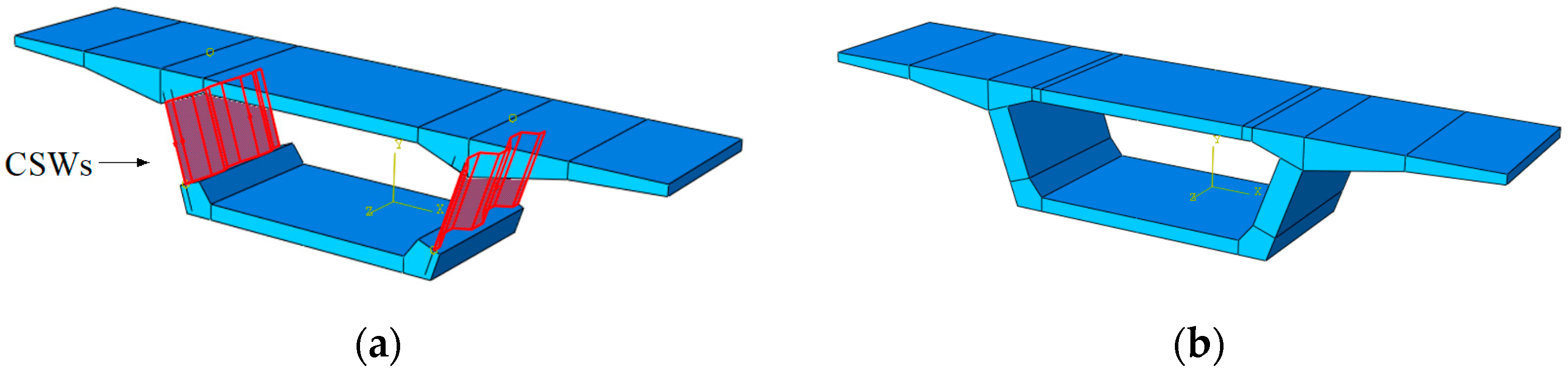
4. Comparison of the Mechanical Properties of the Box Girder Segments with Different Webs

The maximum principal stress of the concrete roof and the overall deformation of a single segment of precast segmental composite box girders with corrugated steel webs and precast segmental concrete box girders under different storage layers and numbers of hoisting points are analysed by the finite element analysis, and the results are shown in Figure 7 and Figure 8. The colour in the figure represents the size of the deformation, and the colour ranges from blue to green to red, representing the continuous increase of the deformation. The same is true for all the pictures with colours. “PS-CBGCSWs-1” in Figure 7 refers to the precast segmental composite box girders with corrugated steel webs stored in one layer, and the other following the same naming scheme.
In terms of stress, when single-layer storage is used, the stress of the roof of a precast segmental composite box girder with corrugated steel webs is slightly larger than that of precast segmental concrete box girders. When double-layer and triple-layer storage are used, the roof stress of the precast segmental composite box girders with corrugated steel webs is much larger than that of the precast segmental concrete box girders. Among them, when three layers are used for storage, the stress of the roof of the precast segmental composite box girders with corrugated steel webs exceeds 2 MPa, which has a great risk of cracking. It can be seen from Figure 8d that regardless of the hoisting method used, the roof stress of the precast segmental composite box girders with corrugated steel webs is much larger than that of the precast segmental concrete box girders in the hoisting period.
In terms of deformation, the deformation of the roof in the project is generally controlled within 4 mm. For the precast segmental concrete box girders, the deformation of the concrete roof is within 4 mm regardless of the storage period or the hoisting period. For the precast segmental composite box girders with corrugated steel webs, the roof deformation is 2.75 < 4 mm only when the single layer is stored, and the deformation values of the other storage or hoisting solutions are far greater than the control requirements.
Comparing the precast segmental composite box girders with corrugated steel webs with the precast segmental concrete box girders, the stress and deformation of the roof are larger in both the storage period and the hoisting period. In particular, the deformation of the roof of the precast segmental composite box girders with corrugated steel webs is much larger than that of the precast segmental concrete box girders, with an amplitude of approximately 70–80%. Therefore, it is necessary to analyse the precast segmental composite box girders with corrugated steel webs specifically.

5. Analysis of the Mechanical Performance of the Single Segment of a Precast Segmental Composite Box Girder with Corrugated Steel Webs during Storage

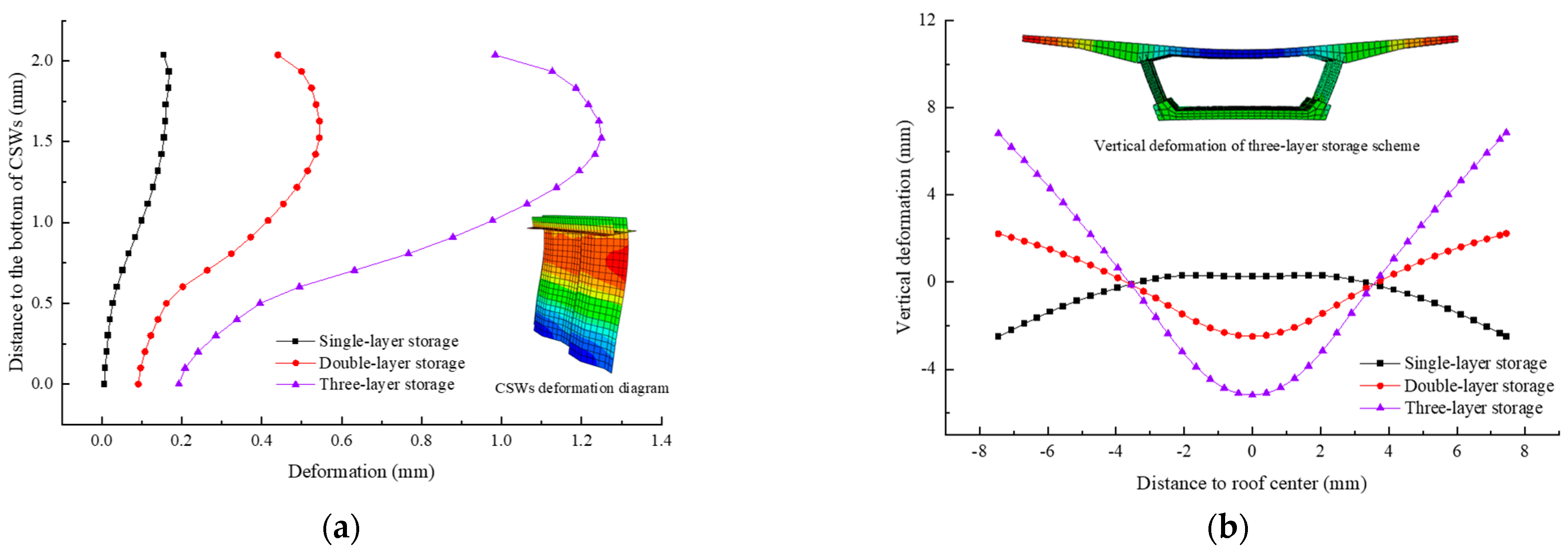
5.1. Number of Storage Layers

Through the finite element analysis, the maximum principal stress of the concrete roof, the maximum stress of the corrugated steel web, the deformation of the corrugated steel web, and the overall deformation of the segment are analysed in detail under the storage schemes of one layer, two layers and three layers of the 3.2 m segment (here, the vertical deformation of the concrete roof of the lowermost segment is analysed; if there is no explanation below, the deformation and stress of the roof come from the roof of the lowermost segment). The results are shown in Table 2 and Figure 9.
In terms of stress, the main tensile stress on the lower surface of the concrete roof of the triple-layer storage model reaches 2.56 MPa, which is beyond the safe range; the concrete principal stress and corrugated steel web stress of the other two storage models have certain safety reserves.
In terms of deformation, when single-layer storage is used, the height difference between the middle of the concrete roof and the flange is within 3 mm, and the deformation of the corrugated steel web is within 0.2 mm; when double-layer storage is used, the height difference between the middle of the concrete roof and the flange exceeds 4 mm, the height difference is too large, and the deformation of the corrugated steel web is within 0.5 mm; when triple-layer storage is used, the height difference between the middle of the concrete roof and the flange is more than 10 mm, the height difference is too large, and the deformation of the corrugated steel web is within 1.2 mm.
The above analysis shows that when the segmental girder is arranged with two layers or more, the concrete stress and deformation of the segmental roof exceed the control limit due to the small stiffness of the CSWs. Therefore, it is necessary to provide temporary rigid supports to the corrugated steel web segment girders for reinforcement during the storage stage (Figure 10). Temporary supports are typically constructed using Q235 channel steel (UPN or UPE in Europe). Channel steel is available in a range of sizes and dimensions, with varying thicknesses and lengths, allowing it to be used for different applications depending on the load requirements. The numbers 12.6, 20, and 32 refer to different cross-sectional area sizes of the channel steel. The cross-sectional area of the 12.6 type channel steel is 15.69 cm2, the cross-sectional area of the 20 type channel steel is 32.83 cm2, and the cross-sectional area of the 32 type channel steel is 48.70 cm2.

5.2. Temporary Support
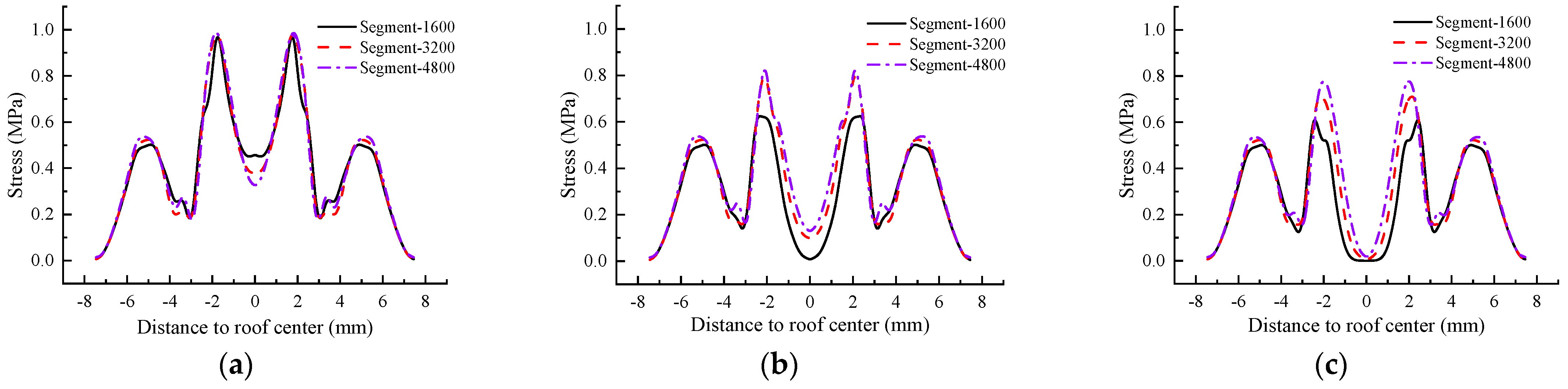
When the segmental girders are stacked with two or more layers, the stress of the concrete segmental roof and the deformation of the girders exceed the control limit, so temporary supports need to be added to the segmental girder segments during storage. In this section, the type and quantity of channel steel used for temporary support of the 3.2 m segment girders are analysed.
As shown in Table 3 and Figure 11 and Figure 12 (12.6-1 means that 12.6 grade steel is adopted for the channel steel model, and the number of support channels is 1), if one support is used, the height difference between the middle of the roof and the flange is 3.33 mm when using channel steel of type 20 with double-layer storage, which meets the requirements, and the deformation amplitude of the support reduction is 31.0%. If two supports are used, the height difference between the middle of the roof and the flange is 3.755 mm when channel steel of type 12.6 is used with double-layer storage, which meets the requirements, and the deformation amplitude of the support reduction is 22.2%. In terms of stress, the maximum stress under several parameter combinations is up to 1.347 MPa, which meets the requirements. For the segment stored on three floors, even if two supports and 32-channel steel are used, the deformation of the roof is still 6.66 mm, and the stress of the roof can reach 1.849 MPa, which does not meet the safety requirements.
Therefore, regardless of whether temporary support is used, the mechanical performance of the segmental girders stored in single layers meets the requirements of the construction standard. When segmental girders are stored in double layers and without temporary support, the height difference between the middle of the concrete roof and the flange exceeds 4 mm, which is too large and does not meet the construction safety requirements. When the segmental girders are stored in double layers and supported by brackets higher than the type 20 channel steel, the force performance is better, and there is a certain safety reserve. When the segmental girders are stored in three layers, regardless of whether a temporary support is used, the deformation of the concrete roof is too large, the main tensile stress of the concrete roof is too large, and the standard requirements are exceeded. In general, with the increase in the type of channel steel and the increase in the number of temporary supports, the concrete roof deformation and stress decrease. Therefore, double-layer storage and a maximum of two layers for precast segments with a segment length of 3.2 m is recommended. Temporary rigid supports should be provided between the top and bottom plates of the segments, the channel steel type should not be less than 20, and 1 to 2 supports are acceptable.

5.3. Segment Length

The above analysis is based on a segment with a length of 3.2 m. In the actual project, there are precast girders with lengths of 1.6 m, 2.4 m, 3.2 m, 4.0 m, and 4.8 m. However, there may be interactions between parameters, such as segment length, number of temporary supports, and channel steel. Therefore, in this section, segment lengths of 1.6 m, 3.2 m, and 4.8 m, and temporary supports of 0–2 channels, and channel steel types of 12.6–32 are selected. Based on the situation in which the segmental girders are stored in the double-layer configuration, a complete testing of the various combinations was performed, and the test results are shown in Table 4 and Table 5.
The stress analysis presented in Table 5 shows that the stress on the concrete roof exhibits a slight increase with an increase in the segment length. However, the stress levels remain well within the safe limit of less than 2 MPa. The concrete roof deformation of the precast segmental composite box girders with corrugated steel webs is also positively correlated with the segment length. When the segment length is 1.6 m, if one to two supports of 12.6 and above type steel are used, the deformation requirements of the concrete roof can be met. When the length of the segment is between 2.4–3.2 m, and one support is used, the channel steel should be 20 grade and above, and if two supports are used, the channel steel should be 12.6 grade and above. When the length of the segment is between 4.0–4.8 m, one to two supports can be used when the channel steel is 20 grade and above.
When the length of the segment is short (such as 1.6–3.2 m), to reduce the roof deformation, choosing one support of a higher steel grade is better than choosing two supports of a lower steel grade. For example, when the segment length is 1.6 m, the roof deformation reduction is 43.2% after one channel of 20 channel steel is selected, while the roof deformation reduction is 37.1% after two channels of 12.6 channel steel are selected. When the length of the segment is long (such as 4.8 m), to reduce the roof deformation, it is better to select two supports with a lower steel grade than one with a higher steel grade. For example, when the segment length is 4.8 m, the roof deformation reduction is 37.2% after two channels of 20 grade steel are selected, and the roof deformation reduction is 30.6% after one channel of 32 grade steel is selected. Hence, when the segment length is short (such as 1.6–3.2 m), the roof deformation is more sensitive to the support size factor. When the segment length is long (such as 4.0 m, 4.8 m), the roof deformation is more sensitive to the support quantity factor. Therefore, with the increase in the segment length, the roof deformation and stress during the storage period increase to a certain extent. In actual engineering, to simplify the process, regardless of the length of the segment, a channel steel of 20 grade and above can be selected, and one to two supports are selected according to the importance of the segment girder. If the safety factor needs to be increased, when the segment length is short (1.6–3.2 m), increasing the support size is recommended. When the segment length is longer (4.0 m, 4.8 m), increasing the number of supports is recommended.

6. Analysis of the Mechanical Performance of a Single Segment of a Precast Segmental Composite Box Girder with Corrugated Steel Webs during Hoisting

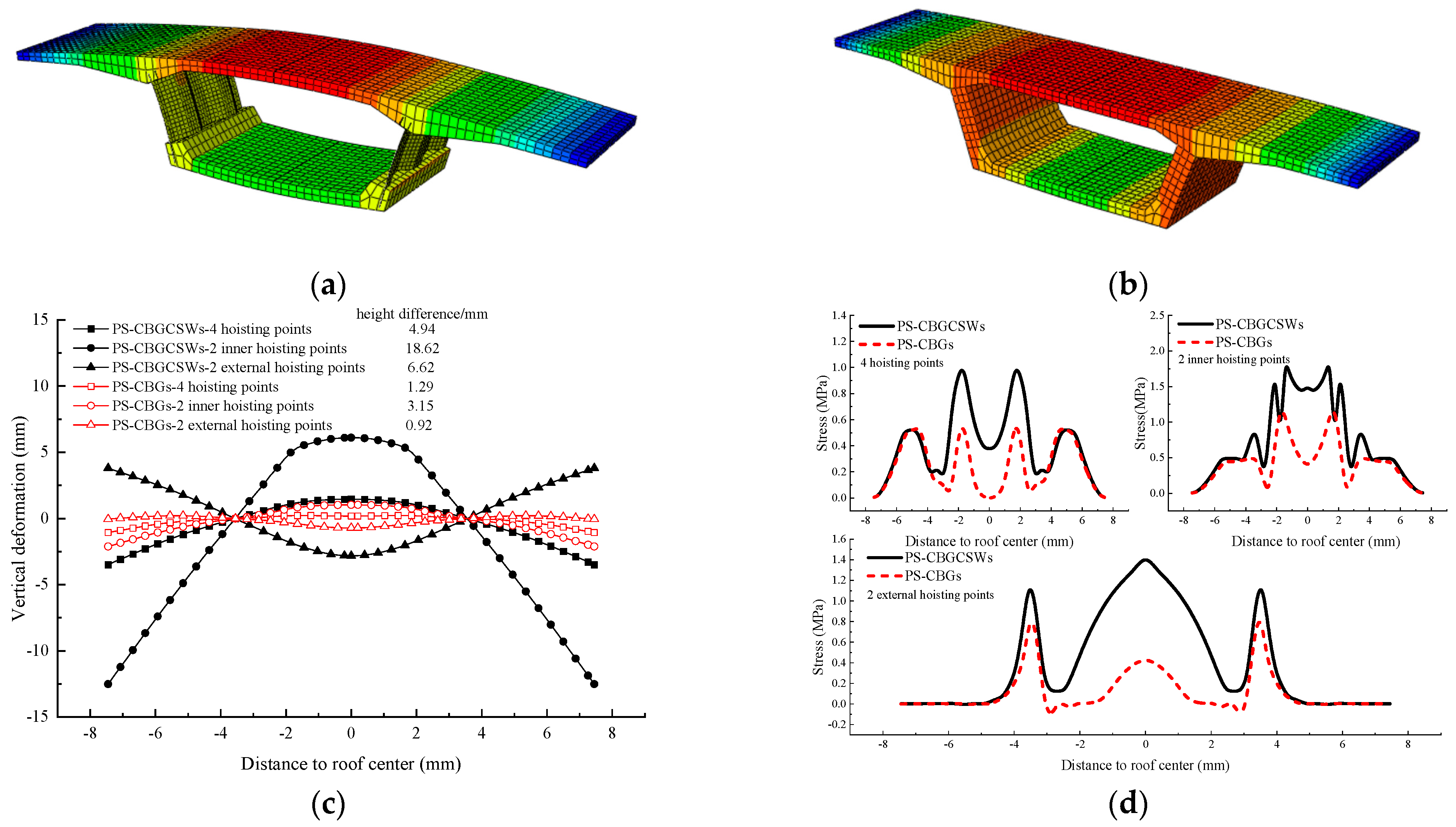
6.1. Number and Location of Hoisting Points

Regarding the hoisting stage of the segment (3.2 m), different hoisting forces F are used to simulate different hoisting periods, and different hoisting schemes are set (see Section 3.2 for details). The results are shown in Table 6 and Figure 13.
In terms of stress, the variation law of the maximum tensile stress of the concrete roof at the four hoisting points and that of the two outer hoisting points are consistent; both first decrease and then increase with the increase in the hoisting force, and both are less than 1.5 MPa. The maximum tensile stress of the concrete roof at the two inner hoisting points first increased to 2.71 MPa with the increase in the hoisting force. At this time, due to the local cracking in the middle of the concrete roof, the maximum tensile stress was reduced to 2.07 MPa. Once the model is raised, the maximum tensile stress of the concrete roof increases linearly from 2.07 MPa to 2.24 MPa with the increase in the hoisting force, then decreases to 1.98 MPa, and then continues to increase to 2.01 MPa.
In terms of deformation, the deformation values of the CSWs of the three hoisting point schemes are within 2 mm. Regarding the concrete roof, the vertical deformation of the four-point hoisting model and that of the two-inner-point hoisting model increase with the increase in the hoisting force, and the deformation is in the form of bulging upwards of the middle of the roof, and the two wings of the roof deform downwards. The vertical deformation of the concrete roof of the model hoisted by the two external hoisting points decreases first and then increases with the increase in the hoisting force, and the deformation is in the form of the middle of the roof deforming downwards, while the two wings deform upwards. The height difference between the middle of the roof and the flange of the four hoisting point hoisting model is approximately 5 mm. The height difference between the middle of the roof and the flange of the two inner hoisting points is 18.6 mm. The height difference between the middle of the roof and the flange of the two outer hoisting points is approximately 6.6 mm.
The above analysis shows that the number and position of the hoisting points play a decisive role, and the influence of acceleration is small. For the stress, the main tensile stress of the concrete roof of the hoisting model with only two inner hoisting points exceeds the safe range. Regarding the deformation of the concrete roof, in the case where there is no rigid temporary support, the height difference between the middle of the concrete roof and the flange in the three types of hoisting schemes is at least 5 mm, and the highest is 18.6 mm. The deformation of the concrete roof is relatively large, so supports must be arranged in the hoisting stage of the precast segmental composite box girders with corrugated steel webs to control the deformation of the girder body.

6.2. Temporary Support

The temporary support arrangement during the hoisting period is shown in Figure 10. The channel steel type is 20. If one support is installed, it is arranged in the middle of the segment girder, and if two supports are installed, they are arranged at 1/4 of the girder ends.
Figure 14 depicts the overall deformation of the girder body under different temporary support-ports. Figure 15 shows the vertical deformation and stress diagram of the roof of the hoisting model with different support numbers for the four hoisting point schemes when the acceleration is 1 m/s2 during the hoisting stage. The figure shows that the height differences between the middle and both ends of the roof of the four hoisting point hoisting model when there is no support, one support and two supports are approximately 4.93 mm, 3.71 mm and 3.02 mm, respectively. The amplitudes of height difference reduction between the middle and both ends of the roof by setting supports are 24.7% and 18.6%, respectively, and the maximum stress values are 0.98 MPa, 0.82 MPa, and 0.71 MPa, respectively. The height differences between the middle and both ends of the roof of the model hoisted by the two inner hoisting points are approximately 18.62 mm, 12.52 mm, and 10.36 mm when there is no support, one support, and two supports, respectively. The amplitudes of height difference reduction between the middle and both ends of the roof by setting supports are 32.8% and 20.5%, respectively. The height differences between the middle of the roof and the two ends of the hoisting model with the two outer hoisting points when there is no support, one support, and two supports are approximately 6.62 mm, 5.2 mm, and 4.41 mm, respectively. The amplitudes of the height difference reduction between the middle and both ends of the roof by setting supports are 31.1% and 18.8%, respectively. Therefore, the two inner hoisting point and two outer hoisting point schemes do not meet the deformation requirements regardless of whether the support is set, and the four hoisting point scheme can meet the deformation requirements when one or two supports are set.

6.3. Segment Length

The above analysis is based on the 3.2 m segment. In practice, the heavier weight of the 4.8 m segment may have an adverse effect on the mechanical performance during the hoisting period. In this section, based on the four hanging point scheme using 20-channel steel, the effects of segment length and the number of supports on the mechanical performance of the segment (mainly the deformation and stress of the roof) are quantitatively studied.
Figure 16 and Figure 17 show the vertical deformation and stress diagrams of the hoisting model roof with different numbers of supports, when the acceleration is 1 m/s2 during the hoisting stage. It can be observed from the figure that when there is no support, the deformation and stress of the roof are basically the same for the 1.6 m, 3.2 m, and 4.8 m segment girders. Once the temporary support is adopted, the deformation and stress of the roof for the segmental girders are in the following order from high to low: 4.8 m, 3.2 m, and 1.6 m.
In terms of deformation, when one support is used, the height differences between the middle and both ends of the 1.6 m, 3.2 m, and 4.8 m segment girder roofs are approximately 3.06 mm, 3.71 mm, and 4.03 mm, respectively. When two supports are used, the height differences between the middle and both ends of the 1.6 m, 3.2 m, and 4.8 m segment girder roofs are approximately 2.38 mm, 3.02 mm, and 3.42 mm, respectively. In terms of stress, regardless of the length of the segment and the number of temporary supports, the stress is below 1.0 MPa, which meets the safety requirements.
Therefore, with the increase in the segment length, the deformation and stress of the roof during the hoisting period increases to a certain extent. When the scheme with 20 channel steel and four hoisting points is adopted, due to the large weight of the 4.8 m segment girder, at least two temporary supports are required to meet the roof deformation requirements. Regarding segmental girders with smaller lengths (below 4.0 m), one support can meet the requirements.

7. Conclusions

This paper takes the Nanjing Fifth Yangtze River Bridge approach bridge-Lixin Road overpass as the background. The differences (mainly stress and deformation) between the precast segmental composite box girders with corrugated steel webs and ordinary precast segmental concrete box girders were compared, and the optimization design of the precast segmental composite box girders with corrugated steel webs storage and hoisting was carried out. The conclusions are as follows:
  • Compared with precast segmental concrete box girders, due to the weaker torsional and lateral stiffness of the precast segmental composite box girders with corrugated steel webs, regardless of the storage period or the hoisting period, the roof stress and deformation are larger. In particular, the roof deformation of the precast segmental composite box girders with corrugated steel webs is much larger than that of the precast segmental concrete box girders, and the amplitude is approximately 70–80%;
  • Due to the low rigidity of CSWs, it is recommended that precast segmental composite box girders with corrugated steel webs should be stored in double layers and should not exceed two layers. Temporary rigid supports should be set between the top and bottom plates of segment girders, the channel steel type should not be less than 20, and one to two supports can be used;
  • The four-hoisting point scheme should be adopted for the hoisting of the precast segmental composite box girders with corrugated steel webs segment, that is, four hoisting points should be set near the web to meet the force requirements during the structural hoisting process. We set one to two channels of not less than 20 type channel steel supports between the top and bottom plates (two for 4.8 m segment girders) to prevent the box girders from becoming deformed too much during the hoisting process;
  • With the increase in the segment length, the deformation and stress of the roof will increase to a certain extent regardless of the storage period and the hoisting period. To simplify the process, 20 grade channel steel and above can be selected regardless of the length of the segment, and one or two supports are selected according to the importance of the segment girder (two supports are required for the 4.8 m segment girder during the hoisting period). If the safety factor needs to be increased, when the segment length is short (1.6–3.2 m), increasing the support size is recommended. When the segment length is longer (4.0 m, 4.8 m), increasing the number of supports is recommended.

Author Contributions

Q.S.: investigation, data curation, formal analysis, validation, writing—original draft. W.D.: methodology, validation, conceptualization, writing—review and editing. D.L.: investigation, conceptualization, writing—review and editing. Z.P. and H.P.: investigation, data curation. J.Z.: methodology, conceptualization, writing—review and editing. All authors have read and agreed to the published version of the manuscript.

Funding

National Natural Science Foundation of China (Grant 51908282), Project of Science and Technology of Department of Transportation of Jiangxi Province (2022H0019), Shandong Provincial Department of Transportation Science and Technology Project (2020B47).

Data Availability Statement

Data will be made available upon request.

Acknowledgments

This study was supported by the National Natural Science Foundation of China (Grant 51908282), the Jiangsu Province Basic Research Program Youth Fund Project (Grant BK20190681), and Shandong Provincial Department of Transportation Science and Technology Project (2020B47). Their financial support is gratefully acknowledged.

Conflicts of Interest

The authors declare no conflict of interest.

References

  1. Saleem, M.A.; Zafar, M.N.; Saleem, M.M.; Xia, J. Recent developments in the prefabricated bridge deck systems. Case Stud. Constr. Mater. 2021, 15, e00750. [Google Scholar] [CrossRef]
  2. Wang, X.; Du, Q.; Lu, C.; Li, J. Exploration in carbon emission reduction effect of low-carbon practices in prefabricated building supply chain. J. Clean. Prod. 2022, 368, 133153. [Google Scholar] [CrossRef]
  3. Zhou, J.; Li, Y.; Ren, D. Quantitative study on external benefits of prefabricated buildings: From perspectives of economy, environment, and society. Sustain. Cities Soc. 2022, 86, 104132. [Google Scholar] [CrossRef]
  4. Aghasizadeh, S.; Tabadkani, A.; Hajirasouli, A.; Banihashemi, S. Environmental and economic performance of prefabricated construction: A review. Environ. Impact Assess. Rev. 2022, 97, 106897. [Google Scholar] [CrossRef]
  5. He, Z.Q.; Li, Y.; Xu, T.; Ma, Z.J. Crack-based serviceability assessment of post-tensioned segmental concrete box-girder bridges. Struct. Elsevier 2021, 30, 1097–1108. [Google Scholar] [CrossRef]
  6. Yan, W.T.; Han, B.; Xie, H.B.; Li, P.F.; Zhu, L. Research on numerical model for flexural behaviors analysis of precast concrete segmental box girders. Eng. Struct. 2020, 219, 110733. [Google Scholar] [CrossRef]
  7. Sheng, X.; Zhou, T.; Huang, S.; Cai, C.; Shi, T. Prediction of vertical temperature gradient on concrete box-girder considering different locations in China. Case Stud. Constr. Mater. 2022, 16, e01026. [Google Scholar] [CrossRef]
  8. Yuan, M.; Yan, D.; Zhong, H.; Liu, Y. Experimental investigation of high-cycle fatigue behavior for prestressed concrete box-girders. Constr. Build. Mater. 2017, 157, 424–437. [Google Scholar] [CrossRef]
  9. Ahmed, G.H.; Aziz, O.Q. Shear behavior of dry and epoxied joints in precast concrete segmental box girder bridges under direct shear loading. Eng. Struct. 2019, 182, 89–100. [Google Scholar] [CrossRef]
  10. Huang, L.; Hikosaka, H.; Komine, K. Simulation of accordion effect in corrugated steel web with concrete flanges. Comput. Struct. 2004, 82, 2061–2069. [Google Scholar] [CrossRef]
  11. Oh, J.Y.; Lee, D.H.; Kim, K.S. Accordion effect of prestressed steel beams with corrugated webs. Thin-Walled Struct. 2012, 57, 49–61. [Google Scholar] [CrossRef]
  12. Inaam, Q.; Upadhyay, A. Accordion effect in bridge girders with corrugated webs. J. Constr. Steel Res. 2022, 188, 107040. [Google Scholar] [CrossRef]
  13. Zhou, M.; Liu, Z.; Zhang, J.; An, L.; He, Z. Equivalent computational models and deflection calculation methods of box girders with corrugated steel webs. Eng. Struct. 2016, 127, 615–634. [Google Scholar] [CrossRef] [Green Version]
  14. Kim, K.S.; Lee, D.H.; Choi, S.M.; Choi, Y.H.; Jung, S.H. Flexural behavior of prestressed composite beams with corrugated web: Part I. Development and analysis. Compos. Part B Eng. 2011, 42, 1603–1616. [Google Scholar] [CrossRef]
  15. Kim, K.S.; Lee, D.H. Flexural behavior of prestressed composite beams with corrugated web: Part II. Experiment and verification. Compos. Part B Eng. 2011, 42, 1617–1629. [Google Scholar] [CrossRef]
  16. He, J.; Liu, Y.; Chen, A.; Yoda, T. Mechanical behavior and analysis of composite bridges with corrugated steel webs: State-of-the-art. Int. J. Steel Struct. 2012, 12, 321–338. [Google Scholar] [CrossRef]
  17. Chen, Y.; Dong, J.; Tong, Z.; Jiang, R.; Yue, Y. Flexural behavior of composite box girders with corrugated steel webs and trusses. Eng. Struct. 2020, 209, 110275. [Google Scholar] [CrossRef]
  18. Shi, F.; Wang, D.; Chen, L. Study of flexural vibration of variable cross-section box-girder bridges with corrugated steel webs. Struct. Elsevier 2021, 33, 1107–1118. [Google Scholar] [CrossRef]
  19. Zhu, Y.; Shen, K.; Wan, S.; Brigham, J.C.; Fascetti, A.; Zhou, P. Torsional repair of damaged single-box multi-cell composite box-girder with corrugated steel webs using CFRP. Part I: Experimental investigation. Compos. Struct. 2022, 296, 115920. [Google Scholar] [CrossRef]
  20. Zhang, Z.; Tang, Y.; Li, J.; Hai, L.T. Torsional behavior of box-girder with corrugated web and steel bottom flange. J. Constr. Steel Res. 2020, 167, 105855. [Google Scholar] [CrossRef]
  21. Zhu, Y.; Wan, S.; Shen, K.; Su, Q.; Huang, M. Experimental and numerical study on the nonlinear performance of single-box multi-cell composite box-girder with corrugated steel webs under pure torsion. J. Constr. Steel Res. 2020, 168, 106005. [Google Scholar] [CrossRef]
  22. Wang, C.; Zhang, Y.; Zhang, X.; Li, Y.; Wei, X. Coupled bending-torsion behaviour of single-box multi-cell curved composite box-girders with corrugated-steel-webs. J. Constr. Steel Res. 2022, 196, 107411. [Google Scholar] [CrossRef]
  23. Zhu, Y.; Meng, D.; Zhang, Y.; Hussein, H.H.; He, S. Long-term performance of a continuous box-girder bridge constructed using precast segments with wet ultra-high-performance concrete (UHPC) joints. Case Stud. Constr. Mater. 2022, 17, e01285. [Google Scholar] [CrossRef]
  24. Do, T.A.; Verdugo, D.; Tia, M.; Hoang, T.T. Effect of volume-to-surface area ratio and heat of hydration on early-age thermal behavior of precast concrete segmental box girders. Case Stud. Therm. Eng. 2021, 28, 101448. [Google Scholar] [CrossRef]
  25. Ahmed, G.H.; Aziz, O.Q. Stresses, deformations and damages of various joints in precast concrete segmental box girder bridges subjected to direct shear loading. Eng. Struct. 2020, 206, 110151. [Google Scholar] [CrossRef]
  26. Ahmed, G.H.; Aziz, O.Q. Shear strength of joints in precast posttensioned segmental bridges during 1959-2019, review and analysis. Struct. Elsevier 2019, 20, 527–542. [Google Scholar] [CrossRef]
  27. Ahmed, G.H.; Aziz, O.Q. Influence of intensity & eccentricity of posttensioning force and concrete strength on shear behavior of epoxied joints in segmental box girder bridges. Constr. Build. Mater. 2019, 197, 117–129. [Google Scholar]
  28. Zhang, Z.; Zou, P.; Deng, E.F.; Ye, Z.; Tang, Y.; Li, F.R. Experimental study on prefabricated composite box girder bridge with corrugated steel webs. J. Constr. Steel Res. 2023, 201, 107753. [Google Scholar] [CrossRef]
  29. Zhang, Z.C.; Liu, X.L.; Hu, L.Y.; Wang, Y.; Chen, W.Q.; Xu, R.Q. Zig-zag theory for concrete beams with corrugated steel webs. Eng. Struct. 2022, 258, 114100. [Google Scholar] [CrossRef]
  30. Wang, T.; Ma, J. Shear buckling stress and normalized shear strength of trapezoidal corrugated steel web. J. Build. Eng. 2022, 57, 104807. [Google Scholar] [CrossRef]
  31. Chan, C.L.; Khalid, Y.A.; Sahari, B.B.; Hamouda, A.M.S. Finite element analysis of corrugated web beams under bending. J. Constr. Steel Res. 2002, 58, 1391–1406. [Google Scholar] [CrossRef]
  32. Hassanein, M.F.; Kharoob, O.F. Behavior of bridge girders with corrugated webs: (I) Real boundary condition at the juncture of the web and flanges. Eng. Struct. 2013, 57, 554–564. [Google Scholar] [CrossRef]
  33. Hassanein, M.F.; Kharoob, O.F. Behavior of bridge girders with corrugated webs: (II) Shear strength and design. Eng. Struct. 2013, 57, 544–553. [Google Scholar] [CrossRef]
  34. Hassanein, M.F.; Kharoob, O.F. Shear buckling behavior of tapered bridge girders with steel corrugated webs. Eng. Struct. 2014, 74, 157–169. [Google Scholar] [CrossRef]
  35. Hassanein, M.F.; Elkawas, A.A.; El Hadidy, A.M.; Elchalakani, M. Shear analysis and design of high-strength steel corrugated web girders for bridge design. Eng. Struct. 2017, 146, 18–33. [Google Scholar] [CrossRef]
  36. Mo, Y.L.; Fan, Y.L. Torsional design of hybrid concrete box girders. J. Bridge Eng. 2006, 11, 329–339. [Google Scholar] [CrossRef]
  37. Ding, Y.; Jiang, K.B.; Liu, Y.W. Nonlinear analysis for PC box-girder with corrugated steel webs under pure torsion. Thin-Walled Struct. 2012, 51, 167–173. [Google Scholar] [CrossRef]
  38. Shen, K.; Wan, S.; Mo, Y.L.; Li, X.; Song, A. A softened membrane model for composite box-girders with corrugated steel webs under pure torsion. Eng. Struct. 2018, 173, 357–371. [Google Scholar] [CrossRef]
  39. Zhou, C.; Li, L.; Wang, L. Improved softened membrane model for prestressed composite box girders with corrugated steel webs under pure torsion. J. Constr. Steel Res. 2019, 153, 372–384. [Google Scholar] [CrossRef]
  40. Li, L.; Zhou, C.; Wang, L. Distortion analysis of non-prismatic composite box girders with corrugated steel webs. J. Constr. Steel Res. 2018, 147, 74–86. [Google Scholar] [CrossRef]
  41. Zhou, M.; Liu, Y.; Deng, W.Q.; Hassanein, M.F.; Zhang, H. Transverse analysis of full-scale precast segmental box girder segments with corrugated steel webs: Experimental tests and FE modelling. Eng. Struct. 2019, 187, 231–241. [Google Scholar] [CrossRef]
Figure 1. Bridge schematic: (a) bridge erection process; (b) bridge after assembly; (c) midspan elevation layout (units: cm); (d) standard section layout (units: cm); (e) Link form of steel plate and steel bar.
Buildings 13 00801 g001aBuildings 13 00801 g001b
Figure 2. Finite element model: (a) PS-CBGCSWs; (b) PS-CBGs.
Buildings 13 00801 g002
Figure 3. Constitutive model: (a) concrete constitutive model; (b) constitutive model of steel bars and steel girders.
Buildings 13 00801 g003
Figure 4. The number of storage layers commonly used in engineering: (a) double-layer storage (PS-CBGs); (b) double-layer storage (PS-CBGCSWs); (c) triple-layer storage (PS-CBGs).
Buildings 13 00801 g004
Figure 5. Finite element model (PS-CBGCSWs): (a) single-layer storage; (b) double-layer storage; (c) triple-layer storage.
Buildings 13 00801 g005
Figure 6. Schematic diagram of the number of hoisting points in the hoisting stage: (a) photograph of the hoisting process; (b) four hoisting points (units: cm); (c) two inner hoisting points (units: cm); (d) two external hoisting points (units: cm).
Buildings 13 00801 g006
Figure 7. Deformation and stress of the roof during storage: (a) deformation of PS-CBGCSWs during double-layer storage; (b) deformation of PS-CBGs during double-layer storage; (c) deformation of PS-CBGCSWs and PS-CBGs with different storage layers; (d) stresses of PS-CBGCSWs and PS-CBGs with different storage layers.
Buildings 13 00801 g007aBuildings 13 00801 g007b
Figure 8. Deformation and stress of roof during hoisting: (a) deformation of a PS-CBGCSW with four hoisting points; (b) deformation of a PS-CBG with four hoisting points; (c) deformation of PS-CBGCSWs and PS-CBGs with different hoisting points; (d) stresses of PS-CBGCSWs and PS-CBGs with different hoisting points.
Buildings 13 00801 g008
Figure 9. Deformation diagram of the concrete roof and CSWs: (a) CSW deformation diagram; (b) vertical deformation diagram of the concrete roof.
Buildings 13 00801 g009
Figure 10. Schematic diagram of the temporary support: (a) Schematic diagram of the temporary rigid support (units: cm); (b) channel steel.
Buildings 13 00801 g010
Figure 11. Deformation diagram of the roofs with different support types and quantities during double-layer storage.
Buildings 13 00801 g011
Figure 12. Deformation diagram of the roofs with different support types and quantities during triple-layer storage.
Buildings 13 00801 g012
Figure 13. Variation in the maximum tensile stress of the concrete roof with applied force.
Buildings 13 00801 g013
Figure 14. The overall deformation diagram of the girder body under the different temporary supports: (a) zero support; (b) one support; (c) two supports.
Buildings 13 00801 g014
Figure 15. Vertical deformation and stress diagram of the roof of the hoisting model with four hoisting points with different numbers of supports: (a) vertical deformation diagram of the roof of the four hoisting point model; (b) stress diagram of the roof of the four hoisting point model.
Buildings 13 00801 g015
Figure 16. Vertical deformation diagram of the roof of the hoisting model with different numbers of supports: (a) zero support; (b) one support; (c) two supports.
Buildings 13 00801 g016
Figure 17. Stress diagram of the roof plate of the hoisting model with different numbers of supports: (a) zero support; (b) one support; (c) two supports.
Buildings 13 00801 g017
Table 1. Material parameter table.
ComponentMaterialElastic Modulus (MPa)Poisson RatioDensity (t/mm3)
Concrete slabsC503.45 × 1040.22.5 × 10−9
RebarHRB4002 × 1050.37.85 × 10−9
Steel plateQ3452 × 1050.37.85 × 10−9
Scissor supportQ2352 × 1050.37.85 × 10−9
Table 2. Maximum stress of the concrete slab and corrugated steel webs.
SchemeRoof
Max Principal Stress (MPa)
CSWs
Max Stress (MPa)
Roof
Deformation (mm)
Single-layer storage1.0121.022.804
Double-layer storage1.4462.494.829
Triple-layer storage2.58132.1012.000
Table 3. Maximum stress and deformation of the concrete roof.
Channel Steel ModelDouble-Layer StorageTriple-Layer Storage
1 Support2 Supports1 Support2 Supports
Stress
(MPa)
Deformation
(mm)
Stress
(MPa)
Deformation
(mm)
Stress
(MPa)
Deformation
(mm)
Stress
(MPa)
Deformation
(mm)
12.61.3474.2651.2743.7552.40711.1402.25710.181
201.2253.3301.1192.6722.2869.5282.2068.644
321.1792.9741.0582.2782.4319.2641.8496.660
Table 4. Maximum deformation of the concrete roof (mm).
Segment Length (m)0
Support
1 Support2 Supports
12.6203212.62032
1.64.4963.5022.5532.1182.8291.8541.476
3.24.8294.2653.3302.9743.7552.6722.278
4.84.8084.4453.7503.3364.0553.0202.745
Table 5. Maximum stress of the concrete roof (MPa).
Segment Length (m)0
Support
1 Support2 Supports
12.6203212.62032
1.61.3761.2331.0981.0331.1401.0070.936
3.21.4311.3471.2251.1791.2741.1191.058
4.81.4511.4121.3271.2741.3381.1881.143
Table 6. Maximum stress and deformation of the concrete roof and CSWs.
Hoisting Force (kN)Four Hoisting PointsTwo Inner Hoisting PointsTwo External Hoisting Points
Roof Stress
(MPa)
Roof
Deformation
(mm)
CSWs
Deformation
(mm)
Roof Stress (MPa)Roof
Deformation
(mm)
CSWs
Deformation
(mm)
Roof Stress
(MPa)
Roof
Deformation
(mm)
CSWs
Deformation
(mm)
01.022.670.171.022.670.171.022.670.17
175/269/80 10.783.090.222.7112.901.190.610.76−0.03
3121.044.490.442.0716.621.601.24−5.99−0.56
3181.104.670.452.1517.151.661.31−6.11−0.57
3311.144.750.472.2417.831.721.36−6.36−0.60
3441.184.930.492.0118.601.791.42−6.60−0.62
1 Measurements of 175/269/80 in the hoisting force column mean that the hoisting force of the four hoisting points is 175 kN, the hoisting force of the two inner hoisting points is 269 kN, and the hoisting force of the two outer hoisting points is 80 kN.
Disclaimer/Publisher’s Note: The statements, opinions and data contained in all publications are solely those of the individual author(s) and contributor(s) and not of MDPI and/or the editor(s). MDPI and/or the editor(s) disclaim responsibility for any injury to people or property resulting from any ideas, methods, instructions or products referred to in the content.

