
Out-of-Plane Design Equations for Confined Masonry Walls

College of Engineering, Autonomous University of Yucatan, Av. Industrias no Contaminantes s/n por Anillo Periferico Norte, Merida 97302, Mexico
*
Author to whom correspondence should be addressed.
Buildings 2024, 14(4), 913; https://0-doi-org.brum.beds.ac.uk/10.3390/buildings14040913
Submission received: 5 March 2024
/
Revised: 21 March 2024
/
Accepted: 22 March 2024
/
Published: 27 March 2024
(This article belongs to the Section Building Structures)
Abstract
:Nowadays there is still a lack of requirements for the out-of-plane design of confined masonry walls. Current code requirements are mainly based on the in-plane behavior of those walls. This research is divided into two parts. In the first part, two confined walls subjected to out-of-plane uniform loads were tested in the laboratory. Confining elements with minimum cross-section dimensions and wall aspect ratios smaller than one were considered. The variable studied was the wall length. Out-of-plane load—displacement curves of walls were obtained. In the second part, two design equations were developed to determine the out-of-plane strength of confined walls. A design equation was developed to determine the corresponding in-plane forces transferred to the confining elements. The out-of-plane strength of 6912 walls was determined using a computer program based on the bidirectional strut method. A parametric analysis was carried out for the out-of-plane strength considering different variables. Multiple linear regression analyses were carried out to propose out-of-plane strength design equations. It was concluded that the experimental out-of-plane strength increased, and the wall failure type changed as the wall length decreased. In addition, the experimental out-of-plane strength of walls was well predicted with both out-of-plane design equations.
1. Introduction
Earthquakes and cyclones have caused significant problems related to human deaths, financial losses, and damaged infrastructure, among others [1]. Various types of infrastructure have been damaged, such as masonry structures and concrete frames. Masonry structures are commonly used for the construction of houses, hotels, and offices, among others. The walls of a masonry structure that is under seismic or wind actions, can be subjected to in-plane and out-of-plane loads. These out-of-plane loads can cause the collapse of walls [2,3].
The out-of-plane behavior of masonry walls can be studied with experimental testing, analytical methods, and numerical modeling [4]. There are experimental studies on the behavior of walls subjected to out-of-plane loads for unreinforced [5,6,7,8], infill [9,10,11,12,13], and confined masonry walls [14,15,16,17,18,19,20,21,22]. The number of these studies is limited compared with those carried out for the in-plane behavior of these walls [23,24]. The main variables considered were the compressive strength of masonry, unit type, aspect ratio (height over length), slenderness ratio (height over thickness), support conditions, axial load, wall openings, and in-plane stiffness of the surrounding frame elements of walls. There are differences in the out-of-plane behavior of unreinforced, infill, and confined masonry walls. Out-of-plane load capacity after the first cracks is greater for infill and confined walls than for unreinforced walls. This is associated with the in-plane restriction provided by the frame elements surrounding the wall panel. The difference in the construction procedure between infill and confined walls changes their out-of-plane behavior. The wall panel is constructed after the surrounding frame elements in infill walls, while the wall panel is constructed before the surrounding reinforced concrete frame elements in confined walls. The construction gaps between the wall panel and the surrounding elements in the infill walls delay the formation of an arching action mechanism.
In particular, the out-of-plane behavior of confined walls is associated with the formation of horizontal, vertical, and diagonal cracks that divide the wall into wall segments [15,16,17,19,20,22]. As the uniform out-of-plane loads increase, the wall segments rotate and develop a two-way arching action mechanism. Compressive strut forces are developed in the wall segments. These forces are transferred to the frame of concrete confining elements as in-plane forces. The out-of-plane strength is determined by the equilibrium between the acting uniform loads and the out-of-plane components of the compressive strut forces. Two types of wall panel failure can be observed: crushing of masonry and snap-through of wall segments. It is observed that, in general, the cross-section dimensions of confined walls tested in those studies were greater than the minimum specified in the codes. Dimensions of confining elements were increased in those studies to avoid their local failure. Therefore, additional experimental tests of confined walls with flexible confining elements and aspect ratios less than or equal to one, as commonly used in construction practice, are needed.
Different analytical methods have been developed to determine the out-of-plane strength of masonry walls, such as the compressive strut method [10,16], yield line method [9,16,25], and failure line method [16,25]. In addition, different numerical models have been developed to calculate the out-of-plane strength of masonry walls, such as the spring-strut method [16], bidirectional strut method [26], two-dimensional fictitious truss [23], finite element method [27,28,29], discrete element method [30,31], and lattice discrete particle model [32], among others. The analytical and numerical methods mentioned have different levels of complexity and computational cost, and their accuracy in predicting the out-of-plane strength of walls varies depending on the type of masonry wall. In particular, the out-of-plane strength of confined walls is best predicted with the bidirectional strut method [26]. This method has a low computational cost and is summarized later in this paper. In the bidirectional strut method, failure of the unreinforced panel is considered. However, the out-of-plane strength of walls can be also limited by the local failure of concrete confining elements [20], for example, flexural, shear, and torsional failure of those elements.
Confined masonry walls are widely used in many countries in Latin America, Asia, Europe, and Africa [33,34]. Most of the requirements prescribed in design codes for confined walls are based on their in-plane behavior (e.g., Norm-E.070 in Peru [35]; NSR-10 in Colombia [36]; NTC—Masonry in Mexico [37]). For example, in Mexico, the maximum spacing of confining elements is based on the observed in-plane shear behavior of confined walls. There are few design requirements for the out-of-plane design of this type of wall. For example, the out-of-plane strength of cantilever walls should be provided by the vertical confining elements. In this case, these elements are required to prevent the overturning of the entire wall. In general, the interaction between the unreinforced masonry panel and the surrounding reinforced concrete confining elements is not considered. This interaction is important for the out-of-plane design of confined and infill walls [9,10,11,12,15,16,17,38]. There is an out-of-plane design procedure for confined masonry walls that considers this interaction [20]. In this procedure, the confining elements are analyzed with a frame element model. This procedure has two main steps: (1) determination of the out-of-plane strength of confined walls and (2) determination of the corresponding in-plane forces transferred to the concrete confining elements. Both steps can be carried out using the bidirectional strut method. Unfortunately, this method is iterative and needs to be implemented in a computer program. Therefore, the method is difficult to use in engineering practice. This shows the need to develop simplified design equations to determine the out-of-plane strength of confined walls with any aspect ratio, as well as design equations for the in-plane forces transferred to the confining elements of walls. In addition, it is desirable to include a wider range of variables than those considered in experimental studies. This can be executed by performing numerical simulations.
The first objective of this work was to test confined masonry walls with minimum cross-section dimensions of confining elements as specified in codes. These cross-section dimensions are typically used in construction practice. Walls with an aspect ratio smaller than one were considered. The second objective was to develop design equations to determine the out-of-plane strength and the corresponding in-plane forces transferred to the confining elements of walls with different aspect ratios. In the first part, two confined walls subjected to out-of-plane uniform loads were tested in the laboratory. The variable studied was the wall length. In the second part, the out-of-plane strength of 6912 walls was determined using a computer program based on the bidirectional strut method. A parametric analysis was carried out for the out-of-plane strength considering different variables. Two design equations were developed for the out-of-plane strength. A design equation was developed for the corresponding in-plane forces transferred to the confining elements. It was concluded that the experimental out-of-plane strength increased as the wall length decreased. Snap-through failure of wall segments was observed for the wall with the smaller aspect ratio. Crushing of masonry was observed for the wall with the greater aspect ratio. On the other hand, the experimental out-of-plane strength of walls was well predicted with the out-of-plane design equations developed in this work.
2. Methodology
2.1. Experimental Program
Two full-scale confined walls (M1 and M2) were considered in this research. The total height () and thickness () of walls were 2710 mm and 143 mm, respectively. The total length () of walls M1 and M2 were 3570 mm and 2750 mm, respectively. The variable studied was the wall length (). No axial load was applied to the walls. Concrete blocks with three vertical cells were considered. Dimensions of blocks were 143 mm × 192 mm × 396 mm (thickness × height × length). The block face shells had an average thickness of 26 mm. The ratio between the net and the gross area of blocks was about 0.5. Blocks were obtained from a single batch. Confining elements were designed to induce wall panel failure and avoid their local failure [20]. The minimum dimensions of the cross-section of the confining elements were considered: 150 mm × 150 mm (width × height) [37]. The frames of confining elements subjected to eccentric uniform in-plane loads were analyzed. The models and the loads were proposed based on the bidirectional strut method as described in Section 2.2. Concrete confining elements were designed by flexure, shear, and torsion. Deformed steel bars with a nominal yield strength of 412 MPa were considered for the longitudinal reinforcement (LR). Plain steel bars with a nominal yield strength of 228 MPa were considered for the transverse reinforcement (TR). Plain steel bars are widely used in Mexico. Details of LR and TR in vertical (VCE) and top horizontal (HCE) confining elements are presented in Table 1.
An experienced worker was hired to construct the walls. These were constructed in half-running bonds. Mortar in proportions by volume was 1:2:7 (Portland cement:lime:sand). Mortar was placed on both the head joints and the face shells. The thickness of the mortar joints was about 10 mm. The construction of the walls was in three steps as executed in the southeast part of Mexico. First, seven block courses were laid and later the corresponding part of the vertical concrete confining elements were cast. Second, the next four block courses were laid, and the corresponding part of the vertical confining elements were cast. Lastly, the top confining element was cast.
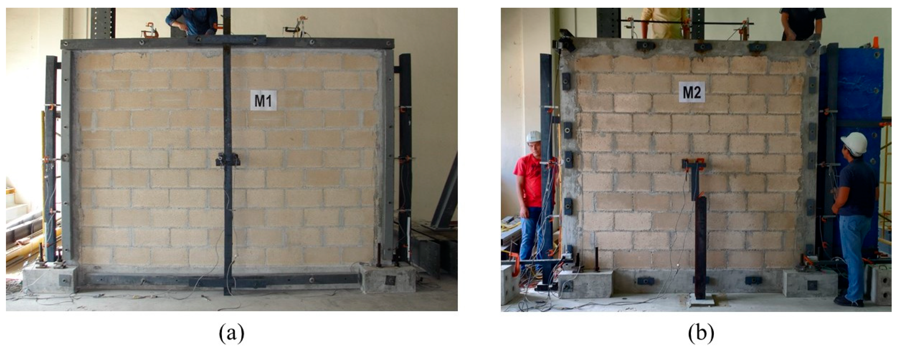
Incremental out-of-plane uniform loads were applied to the walls until failure. The wall test setup is presented in Figure 1. Two airbags of 3.0 m × 1.2 m (length × height) were used to apply these loads. These bags were placed between the wall and a strong reaction wall. Steel threaded bars were placed in the vertical and top confining elements to join the wall to the reaction wall. Confining elements were restricted using simple supports to prevent horizontal out-of-plane displacements. In wall M1, these supports consisted of hollow steel sections with a steel round bar attached to it. In wall M2, these supports consisted of individual steel plates with a steel round bar attached to it. The bottom end of the vertical confining elements was attached to the laboratory’s strong floor to create a fixed support. Pressure transducers were used to measure air bag pressure. Out-of-plane loads reported in this work correspond to equivalent loads. These loads were calculated using the ratio between the contact area of the airbags and the total wall area [22]. Linear potentiometers LP1 and LP2 were used to measure out-of-plane horizontal displacements (Figure 2). Linear potentiometers LP3 to LP14 were used to measure in-plane displacements of the confining elements (Figure 2). A front view of the walls before testing is presented in Figure 3.
The compressive strength of concrete blocks and mortar was determined according to NMX-C-036-ONNCCE-2013 [39] and NMX-C-061-ONNCCE-2015 [40], respectively. The masonry compressive strength and the corresponding modulus of elasticity were determined according to NMX-C-464-ONNCCE-2010 [41]. Masonry flexural tensile strength was determined according to ASTM E 72-2015 [42]. The concrete compressive strength from confining elements was determined according to NMX-C-083-ONNCCE-2014 [43]. The experimental program of this research was similar to that considered in previous works [16,17,19,20,22].
2.2. Bidirectional Strut Method
The out-of-plane strength of confined walls was calculated with a computer program, developed in this work. This program was based on the bidirectional strut method [26]. Details of this method are presented in [44]. In this method, only failure of the wall panel is considered, for example, crushing of masonry and snap through of wall segments. The bidirectional strut method is briefly summarized as follows. An idealized wall cracking pattern is assumed based on the wall aspect ratio (Figure 4). The wall is divided into wall segments. The wall is additionally subdivided into vertical and horizontal strips (Figure 5). Compressive strut forces associated with an arching action mechanism are developed in each strip. The in-plane components of the compressive strut forces (in-plane forces, ) are applied eccentrically to the frame of confining elements (Figure 6). These confining elements are modeled using frame elements with lengths equal to the strip widths. The frame elements have six degrees of freedom per node (three translational displacements and three rotational displacements). The nodes at the bottom of the frame are fixed. All out-of-plane translational displacements of the frame are restricted. It is considered that out-of-plane wall translational displacements are applied at the wall center and that the wall segments rotate in rigid body motion. An increment of the out-of-plane wall displacement is applied in each load step. A structural analysis is performed on the frame of confining elements considering eccentric uniform in-plane loads () acting around the frame (Figure 6). In-plane displacements are computed considering the effects associated with rigid body motion and axial deformation of wall segments, as well as torsion of confining elements. The structural analysis and the computation of the in-plane displacements are repeated until the displacement convergence criterion is satisfied. The out-of-plane strength of confined walls is computed considering the out-of-plane equilibrium between the external loads () and the out-of-plane components of the horizontal and vertical compressive strut forces (Figure 5). The input of the computer program includes the compressive strength of masonry over the net area, wall height, wall length, wall thickness, wall axial load, width, depth, modulus of elasticity, and shear modulus of the confining elements. The output of the computer program for each wall is the out-of-plane strength that is calculated as the sum of the contributions of the compressive struts in the vertical strips, horizontal strips, and the wall axial load, as well as the type of failure and the in-plane loads.
2.3. Primary and Secondary Variables
Primary and secondary variables were considered in this study. Primary variables were the compressive strength of masonry over the net area (), wall height (), wall length (), wall thickness (), depth of the confining elements (), and wall axial compressive stress over the gross area (axial load) (). These variables were selected based on experimental results of confined walls subjected to out-of-plane loads [16,17,19,20,22]. Wall dimensions (H, L) were measured from the longitudinal axes of corresponding confining elements (Figure 4). These wall dimensions were used to define the frame model dimensions (Figure 5). Typical values considered for primary variables are presented in Table 2. Modulus of elasticity () and shear modulus () of concrete of confining elements were assumed constant and equal to 15,260 MPa and 6358 MPa, respectively. These values are widely used for confined masonry in the southeast part of Mexico.
Secondary variables were the wall aspect ratio (H/L) and the in-plane stiffness of the frame of confining elements. This stiffness was divided into a vertical stiffness (), Equation (1), and a horizontal stiffness (), Equation (2). The first equation was determined by applying a unit vertical displacement at the mid-length of a horizontal confining element fixed at both ends. The unit displacement was applied with an eccentricity equal to half of the thickness of the confining element. Similarly, the second equation was determined by applying a unit horizontal displacement at the mid-length of a vertical confining element fixed at both ends. In both equations, flexural and torsional effects were included. In Equation (1), and are the moment of inertia and the torsional constant of the horizontal confining element, respectively. In Equation (2), and are the moment of inertia and the torsional constant of the vertical confining elements, respectively. Based on the combination of the values presented in Table 1, 6912 walls were considered in this study, 1152 walls without axial load and 5760 walls with axial load.
2.4. Design Equations for Out-of-Plane Strength and in-Plane Forces of Confined Walls
The out-of-plane strength and type of failure of the 6912 walls were determined with a computer program developed in this work. This out-of-plane strength was defined as the computational out-of-plane strength (). Based on the results of the computer program, it was observed that in about 90% and 10% of the cases, crushing of masonry and snap-through of wall segments controlled the out-of-plane strength of the walls, respectively. This last type of failure was related to walls with large compressive strength of masonry and small stiffness of confining elements. Because of this reason, design equations were developed considering all the walls together, that is, design equations were not developed for each type of failure. A parametric analysis was carried out for as a function of , , , , , and . The effect of was implicitly considered in and . Results of the analysis were used to define function types and propose wall aspect ratio intervals as presented later.
The first out-of-plane strength design equation was developed for confined walls. The design out-of-plane strength () was defined as the sum of the contributions of the compressive struts in the vertical strips (), horizontal strips (), and the wall axial load (). Computational out-of-plane strength contributions (, , and ) were calculated for the 6192 walls with the computer program. Multiple linear regression analyses were carried out for and as a function of , , , , , and . In addition, a multiple linear regression analysis was carried out for as a function of , , , , , , and . Power functions were selected for the analyses. Variables were normalized to facilitate unit conversions and to determine exponent constants with similar orders of magnitude. The coupling between variables was considered in the selected functions. Three wall aspect ratio intervals were considered: , , and . The coupling between variables and the number of intervals was based on the results of the parametric analysis.
A second out-of-plane strength design equation was developed for confined walls. The out-of-plane strength () was equal to the sum of , , and , as described before. New multiple linear regression analyses were carried out for and as a function of , , , , , and . In addition, a multiple linear regression analysis was carried out for as a function of , , , , , , and . In those cases, and represent the vertical and horizontal in-plane stiffness of confining elements, respectively. In both cases, only flexural effects were included for simplification purposes. Power functions were considered in the analyses. Variables were normalized for the reasons described before. A reduced number of exponent constants was considered for , , and . This reduction was based on the standard error of variables observed in the previous regression analyses. Two wall aspect ratio intervals were considered for simplicity: and .
A design equation was developed for the in-plane forces () transferred to the confining elements. Computational in-plane forces () were calculated for the 6192 walls with the computer program. Multiple linear regression analyses were carried out for the in-plane forces of walls without axial load () as a function of and . Polynomial functions were selected for the analyses. Two wall aspect ratio intervals were considered: and . In addition, a regression analysis was carried out between and ) to consider the effect of axial load on the out-of-plane strength. A power function was considered for this case.
3. Results and Discussion
3.1. Experimental
3.1.1. Material Properties
The average gross compressive strength of blocks and mortar was 4.02 MPa and 3.54 MPa, respectively. The average gross compressive strength and corresponding modulus of elasticity of masonry was 2.43 MPa and 4055 MPa, respectively. The compressive strength of masonry over the net area was 4.97 MPa. The average gross flexural tensile strength of masonry perpendicular to bed joints was 0.14 MPa. The average gross flexural tensile strength of masonry parallel to bed joints was 0.44 MPa. The average compressive strength of concrete for walls M1 and M2 was 27.56 MPa and 26.43 MPa, respectively.
3.1.2. Wall Test
The cracking pattern of the walls was in general similar (Figure 7). Initially, a horizontal crack formed on the central area of wall panels. Later, diagonal cracks formed from the end of the horizontal crack to the corners of the wall panels. Finally, a second horizontal crack was formed parallel to the first one. Before failure, two horizontal cracks and two vertical cracks were observed on the wall face in contact with the airbags. The upper horizontal crack was between the tenth and the eleventh block courses. The lower horizontal crack was between the first and the second block courses. Vertical cracks were located between the concrete confining elements and the wall panel. The final crack distribution observed in the tests (Figure 8) was similar to that observed in previous works [16,17,19,20,22]. An idealized cracking pattern can be defined based on that observed in the test. This one corresponds to the lines of rotation of wall segments considered in the bidirectional strut method. For example, a single horizontal line on the central area of the wall panel is considered (Figure 4) despite that, two cracks were formed on the tested walls. In addition, cracks were observed in the confining elements (Figure 9). Larger cracks were observed in wall M1 compared to M2 and walls tested in previous works [16,17,19,20,22]. This was associated with a larger flexibility of the top horizontal confining element of wall M1 because minimum cross-section dimensions were considered.
The out-of-plane load—displacement curves of walls M1 and M2 are presented in Figure 10. A linear elastic behavior was observed up to the formation of the first cracks. Thereafter, the behavior was nonlinear due to the formation of cracks. Failure of wall M1 was related to snap through of wall segments. Failure of wall M2 was related to crushing of masonry. The difference in the wall failure was related to the wall length and corresponding in-plane stiffness of the top horizontal confining element. For example, the top horizontal confining element of wall M1 was longer and more flexible; therefore, larger in-plane vertical displacements were observed and the wall segments were able to rotate up to the snap through failure. On the other hand, the top horizontal confining element of wall M2 was shorter and stiffer; therefore, smaller in-plane vertical displacements were observed. The compressive strut forces in the wall segments increased as the wall segments rotated. Finally, the corresponding stresses in the wall segments reached the masonry compressive strength. The experimental out-of-plane strength of walls M1 and M2 was 7.53 kPa and 11.25 kPa, respectively; these values are indicated with markers in Figure 10. It was observed that the out-of-plane strength increased as the wall length decreased.
3.2. Parametric Analysis
Typical results of the parametric analyses are presented in Figure 11, Figure 12, Figure 13, Figure 14, Figure 15, Figure 16 and Figure 17. Variables that were kept constant in the analyses are included in the corresponding figures. It was observed that as , , , and increased, increased (Figure 11, Figure 12, Figure 15, Figure 16 and Figure 17). On the contrary, as and increased, decreased (Figure 13 and Figure 14). A relative increase in the out-of-plane strength was observed for walls with an aspect ratio of one (Figure 13). This increment was associated with the change in the idealized cracking pattern used for this aspect ratio (Figure 4). The increment showed the need to use at least two wall aspect ratio intervals for the design equations. In addition, it was observed that, as increased, increased. For walls with the same height, as the wall length decreases, the aspect ratio increases. Walls with small lengths have larger stiffness , and therefore larger out-of-plane strengths (Figure 15). In addition, it was observed that the parameters related to the geometry of the wall panel (, and ) are those that have the greatest influence on the out-of-plane strength of confined masonry walls. The out-of-plane strength of walls is determined by the out-of-plane component of the compressive strut forces that are in the wall segments. This component is a function of the wall geometry. Out-of-plane component of compressive strut forces increases as the wall thickness increases or the wall height or length decreases.
3.3. Design Equations
3.3.1. Out-of-Plane Strength of Confined Walls
The first out-of-plane strength design equation proposed for confined walls () is presented in Equation (3). Corresponding constants , , and are presented in Table 3, Table 4 and Table 5, respectively. The second out-of-plane strength design equation () is presented in Equation (14). In both equations, the out-of-plane strength is in kPa.
where:
If :
If :
The metrics of the multiple linear regression analysis carried out for , , and (Equations (4)–(6)) are presented in Table 6. Similarly, corresponding metrics for , , and (Equations (15)–(20)) are presented in Table 7. It is observed in these tables that a high accuracy was obtained for all the equations. The design out-of-plane strengths ( and ) are compared with corresponding computational out-of-plane strengths () for the 6912 walls (Figure 18 and Figure 19). and were calculated with Equations (3) and (14), respectively, substituting the input information of each wall that was analyzed with the computer program. Figure 18 and Figure 19 have a green reference line to identify cases in which was similar to and , respectively. The average ratio of was equal to 1.00 with a coefficient of variation (CV) of 0.11. The average ratio of was equal to 1.04 with a CV of 0.21. As expected, the out-of-plane strength is better predicted with the first design equation. In this equation, the interaction between the properties of the wall panel and the stiffness of the confining elements were considered by the coupling between variables, for example, coupling between , , , and , with in Equation (4). In addition, in the first design equation, the stiffness of the confining elements was calculated considering flexural and torsional effects. On the other hand, the second design equation is a simplified version of the first one, is easier to use in engineering practice, and predicts well the computational out-of-plane strength.
Experimental results of 20 confined walls subjected to out-of-plane uniform loads are presented in Table 8. In this table, is the experimental out-of-plane strength. Results of walls 1–2 are from this work, while walls 3–10 were taken from [20], walls 11–12 from [16], walls 12–14 from [17], walls 15–18 from [19], and walls 19–20 from [22].
The design out-of-plane strengths ( and ) of the 20 confined walls are compared with corresponding experimental out-of-plane strengths () (Table 9). In this table, wall dimensions with respect to longitudinal axes (H, L) are included (Figure 4). The average ratio between and were 0.97 and 0.91, respectively. The corresponding values of CV were 0.18 and 0.17, respectively. As expected, the first design equation predicted better the experimental out-of-plane strength of walls for the reasons described before.
3.3.2. In-Plane Forces
The design equation proposed for the in-plane forces transferred to the confining elements of walls () is presented in Equation (21). In Equations (22)–(25), can be replaced by or , by or , and by or , respectively. and are in kN/m. , and are in kPa (kN/m2). , , and are in meters.
where:
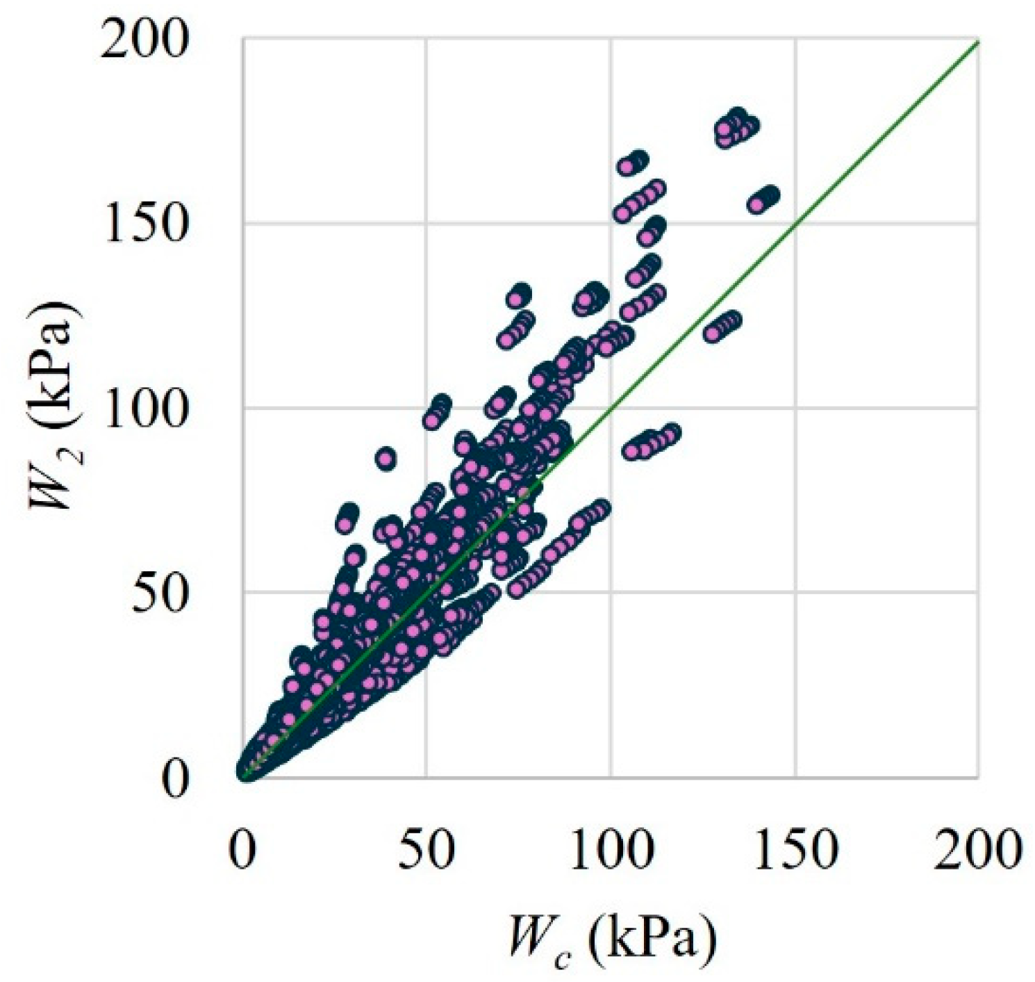
The metrics of the multiple linear regression analysis carried out for (Equations (22) and (23)) are presented in Table 10. It can be observed in this table that a high accuracy was obtained with both equations for . The design () and computational () in-plane forces for walls without axial load are compared in Figure 20. was calculated with Equations (22) and (23), substituting the geometry of each wall that was analyzed with the computer program together with and . Figure 20 has a green reference line to identify cases in which was similar to . The average ratio between was 1.00 with a CV of 0.26. In addition, the ratio between and is compared for walls with axial load in Figure 21. The average ratio of []/[] was 1.00 with a CV of 0.06. It was observed that the computational in-plane forces are well predicted with the design equation. In addition, it was observed that the ratio between was always equal to or less than one (Figure 21). This means that the presence of the axial load reduces the in-plane forces because they are opposite to each other.
4. Conclusions
Two confined walls subjected to out-of-plane uniform loads were tested in the laboratory. The variable studied was the wall length. In addition, two design equations were developed to determine the out-of-plane strength of confined walls. The out-of-plane strength of 6912 walls was determined using a computer program based on the bidirectional strut method. A parametric analysis was carried out for the out-of-plane strength considering primary and secondary variables. A design equation was also developed for the corresponding in-plane forces transferred to the confining elements. Based on the results obtained in this work, the following conclusions are presented:
- The cracking pattern of walls was in general similar. Initially, a horizontal crack formed on the central area of wall panels. Later, diagonal cracks formed from the end of the horizontal crack to the corners of wall panels. Two horizontal cracks and two vertical cracks, located approximately around the wall panel, were observed on the wall face in contact with the airbags. The final cracking pattern of the walls was similar to those observed in previous works for corresponding walls. In addition, larger cracks were observed in the confining elements of wall M1 compared to those of M2 and walls tested in previous works. This was associated with a larger flexibility of the top horizontal confining element of wall M1 because minimum cross-section dimensions were considered.
- The experimental out-of-plane strength increased as the wall length decreased. Failure of wall M1 was related to snap through of wall segments. Failure of wall M2 was related to crushing of masonry. The change in the failure type was related to wall length and the corresponding change in the in-plane stiffness of the top horizontal confining element.
- The computational out-of-plane strength of the confined walls studied was controlled by the crushing of masonry and snap-through of wall segments at about 90% and 10%, respectively. Because of this reason, design equations were developed considering all the walls together, that is, design equations were not developed for each type of failure.
- The out-of-plane strength of confined walls increased as the compressive strength of masonry, the wall thickness, the stiffness of the confining elements, and the wall axial stress increased. On the contrary, this strength decreased as the height and length of walls increased. The parameters related to the geometry of the wall panel (thickness, length, and height) are those that have the greatest influence on the out-of-plane strength of confined masonry walls.
- The computational and experimental out-of-plane strengths of confined walls were better predicted with the first design equation. In this equation, the interaction between the properties of the wall panel and the stiffness of the confining elements was included. In addition, in this equation, the stiffness of the confining elements was calculated considering flexural and torsional effects.
- The second out-of-plane strength design equation is a simplified version of the first one, predicts well the computational and experimental out-of-plane strengths, and was developed for engineering practice.
- The design equation for the in-plane forces transferred to the confining elements predicts well the computational in-plane forces. The presence of the axial load reduces the in-plane forces because they are opposite to each other. This design equation is required to design the reinforced concrete confining elements.
Author Contributions
Conceptualization, L.F.-B., J.V.-R. and J.M.-H.; methodology, L.F.-B., J.V.-R. and J.M.-H.; software, J.M.-H.; validation, L.F.-B., J.V.-R. and J.M.-H.; formal analysis, L.F.-B., J.V.-R. and J.M.-H.; investigation, L.F.-B., J.V.-R. and J.M.-H.; resources, L.F.-B., J.V.-R. and J.M.-H.; data curation, L.F.-B. and J.M.-H.; writing—original draft preparation, L.F.-B. and J.M.-H.; writing—review and editing, L.F.-B. and J.V.-R.; visualization, L.F.-B.; supervision, J.V.-R.; project administration, L.F.-B. and J.V.-R. All authors have read and agreed to the published version of the manuscript.
Funding
The authors acknowledge the support of the Universidad Autonoma de Yucatan, as well as the scholarships that the Consejo Nacional de Humanidades, Ciencias y Tecnologias (CONAHCYT) provided to the students that participated in this research.
Data Availability Statement
The raw data supporting the conclusions of this article will be made available by the authors on request.
Acknowledgments
The authors thank the work done by the following former graduate students: J. G. Canton-Diaz and C. Freyre-Pinto.
Conflicts of Interest
The authors declare no conflict of interest.
References
- Ruggieri, S.; Liguori, F.S.; Leggieri, V.; Bilotta, A.; Madeo, A.; Casolo, S.; Uva, G. An archetype-based automated procedure to derive global-local seismic fragility of masonry building aggregates: META-FORMA-XL. Int. J. Disast. Risk Re. 2023, 95, 103903. [Google Scholar] [CrossRef]
- Shawa, O.A.; Felice, G.; Mauro, A.; Sorrentino, L. Out-of-plane seismic behaviour of rocking masonry walls. Earthq. Eng Struct Dynam 2012, 41, 949–968. [Google Scholar] [CrossRef]
- Fernandez-Baqueiro, L.; Varela-Rivera, J.; Vivas-Pereira, J.; Félix-Solís, E. Evaluación de daños causados por el huracán Wilma en la Riviera Maya. In Proceedings of the XV Congreso Nacional de Ingeniería Estructural, SMIE, Puerto Vallara, Jalisco, México, 1 November 2006. (In Spanish). [Google Scholar]
- Ferreira, T.M.; Costa, A.A.; Costa, A. Analysis of the out-of-plane seismic behavior of unreinforced masonry: A literature review. Int. J. Archit. Herit. 2015, 9, 949–972. [Google Scholar] [CrossRef]
- Costa, A.A.; Arede, A.; Costa, A.; Guedes, J.; Silva, B. Experimental testing, numerical modelling and seismic strengthening of traditional stone masonry: Comprehensive study of a real Azorian pier. Bull. Earthq. Eng. 2012, 10, 135–159. [Google Scholar] [CrossRef]
- Griffith, M.C.; Vaculik, J. Out-of-plane flexural strength of unreinforced clay brick masonry walls. TMS J. 2007, 25, 53–68. [Google Scholar]
- Derakhshan, H.; Lucas, W.; Visintin, P.; Griffith, M.C. Out-of-plane strength of existing two-way spanning solid and cavity unreinforced masonry walls. Structures 2018, 13, 88–101. [Google Scholar] [CrossRef]
- Malomo, D.; Pinho, R.; Penna, A. Numerical modelling of the out-of-plane response of full-scale brick masonry prototypes subjected to incremental dynamic shake-table tests. Eng. Struct. 2020, 209, 110298. [Google Scholar] [CrossRef]
- Dawe, J.L.; Seah, C.K. Out-of-plane resistance of concrete masonry infilled panels. Can. J. Civil Eng. 1989, 16, 854–864. [Google Scholar] [CrossRef]
- Abrams, D.P.; Angel, R.; Uzarski, J. Out-of-plane strength of unreinforced masonry infill panels. Earthq. Spectra 1996, 12, 825–844. [Google Scholar] [CrossRef]
- Klingner, R.E.; Rubiano, N.R.; Bashandy, T.R.; Sweeney, S.C. Evaluation and analytical verification of shaking table data from infilled frames Part II: Out-of-plane behavior. In Proceedings of the 7th North American Masonry Conference, Masonry Society, South Bend, IN, USA, 2 June 1996. [Google Scholar]
- Tu, Y.H.; Liu, P.M.; Lin, H.P. Out-of-plane seismic behavior of unreinforced masonry in-filled walls. In Proceedings of the Structures Congress 2007 (ASCE), Long Beach, CA, USA, 16 May 2007. [Google Scholar]
- Furtado, A.; Rodrigues, H.; Arêde, A.; Varum, H. Experimental evaluation of out-of-plane capacity of masonry infill walls. Eng. Struct. 2016, 111, 48–63. [Google Scholar] [CrossRef]
- Kazemi, M.T.; Hoseinzadeh Asl, M.; Rahimzadeh Rofooei, F. Shaking table study of a full-scale single storey confined brick masonry building. Sci. Iran 2010, 17, 184–193. [Google Scholar]
- Varela-Rivera, J.; Navarrete-Macias, D.; Fernandez-Baqueiro, L.; Moreno, E.I. Out-of-plane behaviour of confined masonry walls. Eng. Struct. 2011, 33, 1734–1741. [Google Scholar] [CrossRef]
- Varela-Rivera, J.; Moreno-Herrera, J.; Lopez-Gutierrez, I.; Fernandez-Baqueiro, L. Out-of-plane strength of confined masonry walls. J. Struct. Eng.-ASCE 2012, 138, 1331–1341. [Google Scholar] [CrossRef]
- Varela-Rivera, J.; Polanco-May, M.; Fernandez-Baqueiro, L.; Moreno, E.I. Confined masonry walls subjected to combined axial loads and out-of-plane uniform pressures. Can. J. Civil Eng. 2012, 39, 439–447. [Google Scholar] [CrossRef]
- Singhal, V.; Rai, D.C. Seismic behavior of confined masonry walls when subjected to in-plane and out-of-plane loading. In Proceedings of the 10th U.S. National Conference on Earthquake Engineering, Earthquake Engineering Research Institute, Anchorage, AK, USA, 21 July 2014. [Google Scholar]
- Varela-Rivera, J.L.; Chan-Esquivel, S.; Fernández-Baqueiro, L.E.; Moreno-Herrera, J.A. Comportamiento de muros de mampostería confinada con aberturas sujetos a cargas fuera del plano. Concreto Cem. Investig. Desarro. 2015, 7, 52–65. (In Spanish) [Google Scholar]
- Moreno-Herrera, J.; Varela-Rivera, J.; Fernandez-Baqueiro, L. Out-of-plane design procedure for confined masonry walls. J. Struct. Eng.-ASCE 2016, 142, 04015126. [Google Scholar] [CrossRef]
- Bahreini, V.; Mahdi, T.; Najafizadeh, M.M. Evaluation of brick infill walls under in-plane and out-of-plane loading. J. Vibroeng. 2017, 19, 394–408. [Google Scholar] [CrossRef]
- Varela-Rivera, J.; Moreno-Herrera, J.; Fernandez-Baqueiro, L.; Cacep-Rodriguez, J.; Freyre-Pinto, C. Out-of-plane behavior of confined masonry walls with aspect ratios greater than one. Can. J. Civil Eng. 2021, 48, 89–97. [Google Scholar] [CrossRef]
- Ridwan, M.; Yoshitake, I.; Nassif, A.Y. Two-dimensional fictitious truss method for estimation of out-of-plane strength of masonry walls. Constr. Build. Mater. 2017, 152, 24–38. [Google Scholar] [CrossRef]
- Perez Gavilan Escalante, J.J.; Brzev, S.; Espinosa Cazarin, E.F.; Ganzerli, S.; Quiun, D.; Reiter, M.T. Experimental research studies on seismic behaviour of confined masonry structures: Current status and future needs. Buildings 2023, 13, 1776. [Google Scholar] [CrossRef]
- Drysdale, R.G.; Essawy, A.S. Out-of-plane bending of concrete block walls. J. Struct. Eng. 1988, 114, 121–133. [Google Scholar] [CrossRef]
- Moreno-Herrera, J.; Varela-Rivera, J.; Fernandez-Baqueiro, L. Bidirectional strut method: Out-of-plane strength of confined masonry walls. Can. J. Civil Eng. 2014, 41, 1029–1035. [Google Scholar] [CrossRef]
- Lourenço, P.B. Anisotropic softening model for masonry plates and shells. J. Struct. Eng. ASCE 2000, 126, 1008–1016. [Google Scholar] [CrossRef]
- Milani, G.; Lourenço, P.; Tralli, A. Homogenization approach for the limit analysis of out-of-plane loaded masonry walls. J. Struct. Eng. ASCE 2006, 132, 1650–1663. [Google Scholar] [CrossRef]
- Noor-E-Khuda, S.; Dhanasekar, M.; Thambiratnam, D.P. An explicit finite element modelling method for masonry walls under out-of-plane loading. Eng. Struct 2016, 113, 103–120. [Google Scholar] [CrossRef]
- Casolo, S. Modelling the out-of-plane seismic behaviour of masonry walls by rigid elements. Earthq. Eng. Struct. Dyn. 2000, 29, 1797–1813. [Google Scholar] [CrossRef]
- De Felice, G. Out-of-plane seismic capacity of masonry depending on wall section morphology. Int. J. Archit. Herit. 2011, 5, 466–482. [Google Scholar] [CrossRef]
- Mercuri, M.; Pathirage, M.; Gregori, A.; Cusatis, G. Computational modeling of the out-of-plane behavior of unreinforced irregular masonry. Eng. Struct. 2020, 223, 111181. [Google Scholar] [CrossRef]
- Tena-Colunga, A.; Mena-Hernández, U.; Pérez-Rocha, L.; Avilés, J.; Ordaz, M.; Vilar, J. Updated Seismic Design Guidelines for Model Building Code of Mexico. Earthq. Spectra 2009, 25, 869–898. [Google Scholar] [CrossRef]
- Marques, R.; Lourenço, P.B. Structural behaviour and design rules of confined masonry walls: Review and proposals. Constr. Build. Mater. 2019, 217, 137–155. [Google Scholar] [CrossRef]
- Servicio Nacional de Capacitación para la Industria de la Construcción (SENCICO). Norma E.070—Albañilería; SENICO: Lima, Peru, 2020. (In Spanish) [Google Scholar]
- Ministerio de Ambiente, Vivienda y Desarrollo Territorial (MAVDT). NSR-10 Reglamento Colombiano de Construcción Sismo Resistente; MAVDT: Bogotá, Colombia, 2010. (In Spanish) [Google Scholar]
- Gobierno de la Ciudad de México (GCM). NTC-Mampostería Normas Técnicas Complementarias para el Diseño y Construcción de Estructuras de Mampostería; GCM: Mexico City, Mexico, 2023. (In Spanish) [Google Scholar]
- Pasca, M.; Liberatorea, L.; Masiani, R. Reliability of analytical models for the prediction of out-of-plane capacity of masonry infills. Struct. Eng. Mech. 2017, 64, 765–781. [Google Scholar]
- Organismo Nacional de Normalización y Certificación de la Construcción y la Edificación (ONNCCE). NMX-C-036-ONNCCE-2013 Industria de la Construcción—Bloques, Tabiques o Ladrillos, Tabicones y Adoquines—Resistencia a la Compresión—Método de Prueba; ONNCCE: Mexico City, Mexico, 2013. (In Spanish) [Google Scholar]
- Organismo Nacional de Normalización y Certificación de la Construcción y la Edificación (ONNCCE). NMX-C-061-ONNCCE-2015 Industria de la Construcción—Cementos Hidráulicos—Determinación de la Resistencia a la Compresión de Cementantes Hidráulicos; ONNCCE: Mexico City, Mexico, 2015. (In Spanish) [Google Scholar]
- Organismo Nacional de Normalización y Certificación de la Construcción y la Edificación (ONNCCE). NMX-C-464-ONNCCE-2010 Industria de la Construcción—Mampostería—Determinación de la Resistencia a Compresión Diagonal y Módulo de Cortante de Muretes, así como Determinación de la Resistencia a Compresión y Módulo de Elasticidad de Pilas de Mampostería de Arcilla o de Concreto—Métodos de Ensayo; ONNCCE: Mexico City, Mexico, 2010. (In Spanish) [Google Scholar]
- ASTM-E-72-2005; Standard Test Methods of Conducting Strength Tests of Panels for Building Construction. ASTM (American Standard Test Methods): West Conshohocken, PA, USA, 2005.
- Organismo Nacional de Normalización y Certificación de la Construcción y la Edificación (ONNCCE). NMX-C-083-ONNCCE-2014 Industria de la Construcción—Concreto—Determinación de la Resistencia a la Compresión de Cilindros de Concreto—Método de Prueba; ONNCCE: Mexico City, Mexico, 2014. (In Spanish) [Google Scholar]
- Moreno-Herrera, J. Propuesta de Diseño Para Muros de Mampostería Confinada Sujetos a Cargas Fuera Del Plano. Ph.D. Thesis, Engineering-Universidad Autonoma de Yucatan, Merida, Yucatan, Mexico, 2014. (In Spanish). [Google Scholar]
Figure 1.
Wall test setup.

Figure 2.
Wall instrumentation.

Figure 3.
Front view of the walls before testing: (a) Wall M1; and (b) Wall M2.

Figure 4.
Idealized cracking pattern of walls.

Figure 5.
Bidirectional strut method models (wall with / < 1).

Figure 6.
In-plane forces on confining elements: (a) frame model subjected to in-plane forces; and (b) torsion caused by eccentric in-plane forces.
Figure 6.
In-plane forces on confining elements: (a) frame model subjected to in-plane forces; and (b) torsion caused by eccentric in-plane forces.

Figure 7.
Crack propagation of wall M1: (a) first crack; (b) diagonal cracks; (c) additional cracks; and (d) final cracking pattern.
Figure 7.
Crack propagation of wall M1: (a) first crack; (b) diagonal cracks; (c) additional cracks; and (d) final cracking pattern.

Figure 8.
Final cracking patterns of walls: (a) M1; and (b) M2.

Figure 9.
Final cracking patterns of top horizontal confining element of walls: (a) M1; and (b) M2.

Figure 10.
Out-of-plane load—displacement curves of walls M1 and M2.

Figure 11.
Effect of on .

Figure 12.
Effect of on .

Figure 13.
Effect of on .

Figure 14.
Effect of on .

Figure 15.
Effect of on .

Figure 16.
Effect of on .

Figure 17.
Effect of on .

Figure 18.
Comparison between the first design equation and computational out-of-plane strengths ().
Figure 18.
Comparison between the first design equation and computational out-of-plane strengths ().

Figure 19.
Comparison between the second design equation and computational out-of-plane strengths ().
Figure 19.
Comparison between the second design equation and computational out-of-plane strengths ().

Figure 20.
Comparison between the design and computational in-plane forces for walls without axial load ().
Figure 20.
Comparison between the design and computational in-plane forces for walls without axial load ().

Figure 21.
Comparison between ratio and ratio for walls with axial load.


Table 1.
Longitudinal and transverse reinforcement details of walls.
| Wall | VCE | HCE | ||
|---|---|---|---|---|
| LR | TR | LR | TR | |
| M1 | 4 No. 3 | No. 2 @ 90 mm (0–0.50 m) No. 2 @ 200 mm (0.50–1.31 m) No. 2 @ 100 mm (1.31–1.81 m) No. 2 @ 50 mm (1.81–2.31 m) | 4 No. 3 | No. 2 @ 50 mm (0–0.40 m, 2.47–2.87 m) No. 2 @ 70 mm (0.40–1.10 m, 1.77–2.47 m) No. 2 @ 200 mm (1.10–1.77 m) |
| M2 | 4 No. 3 | No. 2 @ 40 mm (0–0.30 m) No. 2 @ 70 mm (0.30–0.80 m) No. 2 @ 200 mm (0.80–1.51 m) No. 2 @ 70 mm (1.51–1.91 m) No. 2 @ 40 mm (1.91–2.31 m) | 4 No. 3 | No. 2 @ 40 mm (0–0.30 m, 1.91–2.31 m) No. 2 @ 70 mm (0.30–0.80 m, 1.51–1.91 m) No. 2 @ 200 mm (0.80–1.51 m) |
Table 2.
Values of primary variables.
| Variable | Values | |||||
|---|---|---|---|---|---|---|
| (MPa) | 2 | 4 | 6 | 10 | -- | -- |
| (mm) | 2000 | 2500 | 3000 | -- | -- | -- |
| (mm) | 1500 | 2000 | 2500 | 3000 | 3500 | 4000 |
| (mm) | 100 | 120 | 150 | 200 | -- | -- |
| (mm) | 150 | 200 | 250 | 300 | -- | -- |
| (MPa) | 0 | 0.079 | 0.157 | 0.235 | 0.314 | 0.392 |
Table 3.
Constants used to determine in Equation (4).
| Constant | Intervals | ||
|---|---|---|---|
| 9.6 | 9.0 | 5.5 | |
| −0.325 | −0.305 | −0.26 | |
| 0.189 | 0.189 | 0.146 | |
| 3.41 | 3.27 | 3.34 | |
| −0.309 | −0.242 | −0.237 | |
| −0.099 | −0.029 | 0.087 | |
| −4.36 | −2.53 | 0.387 | |
| 0.639 | 0.456 | −0.122 | |
| −0.838 | −2.43 | −5.32 | |
| 0.222 | 0.204 | 0.737 | |
Table 4.
Constants used to determine in Equation (5).
| Constant | Intervals | ||
|---|---|---|---|
| 14.5 | 0.20 | 0.14 | |
| −0.489 | −0.38 | −0.078 | |
| 0.184 | 0.20 | 0.136 | |
| 4.41 | 3.80 | 2.79 | |
| −0.411 | −0.344 | −0.190 | |
| −0.174 | 0.545 | 0.595 | |
| −7.14 | 0 | 0 | |
| 1.07 | 0.003 | 0.066 | |
| 0.938 | 0 | 0 | |
| −0.213 | −0.26 | −0.287 | |
Table 5.
Constants used to determine in Equation (6).
| Constant | Intervals | ||
|---|---|---|---|
| 6.4 | 6.3 | 12.2 | |
| −0.676 | −0.701 | −0.961 | |
| 0.25 | 0.26 | 0.237 | |
| 0.514 | 0.418 | 0.34 | |
| −0.617 | −0.70 | −0.605 | |
| 0.281 | −0.044 | −0.059 | |
| −0.489 | 0.103 | −0.077 | |
| 1.15 | 1.37 | 1.46 | |
| −0.05 | −0.105 | −0.091 | |
Table 6.
Metrics of the multiple linear regression analysis carried out for , , and .
| Equation | Metrics of the Multiple Linear Regression | |||
|---|---|---|---|---|
| Correlation Coefficient | Coefficient of Determination (R2) | Standard Error | Number of Observations | |
| () | 0.993 | 0.986 | 0.051 | 576 |
| () | 0.982 | 0.964 | 0.077 | 384 |
| () | 0.997 | 0.993 | 0.031 | 384 |
| () | 0.993 | 0.986 | 0.052 | 576 |
| () | 0.974 | 0.949 | 0.091 | 384 |
| () | 0.994 | 0.987 | 0.042 | 384 |
| () | 0.971 | 0.942 | 0.095 | 2879 |
| () | 0.903 | 0.817 | 0.171 | 1920 |
| () | 0.947 | 0.896 | 0.117 | 1917 |
Table 7.
Metrics of the multiple linear regression analysis carried out for , , and .
| Equation | Metrics of the Multiple Linear Regression | |||
|---|---|---|---|---|
| Correlation Coefficient | Coefficient of Determination (R2) | Standard Error | Number of Observations | |
| () | 0.978 | 0.957 | 0.088 | 576 |
| () | 0.988 | 0.975 | 0.061 | 384 |
| () | 0.977 | 0.954 | 0.092 | 576 |
| () | 0.991 | 0.982 | 0.051 | 384 |
| () | 0.972 | 0.945 | 0.092 | 2880 |
| () | 0.904 | 0.817 | 0.164 | 2877 |
Table 8.
Wall properties and experimental out-of-plane strength.
| Wall | (MPa) | (mm) | (mm) | (mm) | (kPa) | (GPa) | (mm) | (mm) | (kPa) |
|---|---|---|---|---|---|---|---|---|---|
| 1 | 4.97 | 3570 | 2710 | 143 | 0.00 | 18.46 | 150 | 150 | 7.53 |
| 2 | 4.97 | 2750 | 2710 | 143 | 0.00 | 18.08 | 150 | 150 | 11.25 |
| 3 | 6.20 | 3770 | 2760 | 113 | 78.45 | 16.79 | 250 | 250 | 8.81 |
| 4 | 6.48 | 3770 | 2760 | 115 | 81.40 | 17.90 | 250 | 250 | 10.49 |
| 5 | 6.17 | 3770 | 2760 | 120 | 79.43 | 17.37 | 250 | 250 | 11.06 |
| 6 | 4.15 | 3770 | 2760 | 114 | 80.41 | 17.90 | 250 | 250 | 7.33 |
| 7 | 6.20 | 2950 | 2760 | 113 | 87.28 | 17.19 | 250 | 250 | 13.44 |
| 8 | 6.48 | 2950 | 2760 | 115 | 92.18 | 17.81 | 250 | 250 | 17.61 |
| 9 | 6.17 | 2950 | 2760 | 120 | 78.45 | 17.64 | 250 | 250 | 18.06 |
| 10 | 4.15 | 2950 | 2760 | 114 | 85.32 | 17.59 | 250 | 250 | 14.24 |
| 11 | 5.68 | 2950 | 2720 | 144 | 0.00 | 14.66 | 250 | 250 | 16.51 |
| 12 | 4.08 | 2950 | 2720 | 116 | 0.00 | 16.37 | 250 | 250 | 14.26 |
| 13 | 5.28 | 3700 | 2700 | 144 | 65.70 | 16.39 | 200 | 200 | 14.59 |
| 14 | 5.28 | 3700 | 2700 | 144 | 196.13 | 16.99 | 200 | 200 | 15.96 |
| 15 | 6.22 | 3570 | 2710 | 144 | 0.00 | 17.13 | 150 | 170 | 10.01 |
| 16 | 6.22 | 2490 | 2710 | 144 | 151.02 | 17.13 | 150 | 170 | 18.43 |
| 17 | 6.22 | 2490 | 2710 | 144 | 0.00 | 17.13 | 150 | 170 | 14.78 |
| 18 | 6.22 | 2490 | 2710 | 144 | 0.00 | 17.13 | 150 | 170 | 15.79 |
| 19 | 5.96 | 1930 | 2710 | 145 | 0.00 | 18.19 | 150 | 150 | 19.72 |
| 20 | 5.96 | 1930 | 2710 | 145 | 340.20 | 18.32 | 150 | 150 | 24.23 |
Table 9.
Comparison between design and experimental out-of-plane strengths.
| Wall | (mm) | (mm) | (kPa) | (kPa) | (kPa) | |||
|---|---|---|---|---|---|---|---|---|
| 1 | 3420 | 2560 | 0.75 | 7.53 | 6.27 | 6.06 | 0.83 | 0.80 |
| 2 | 2600 | 2560 | 0.98 | 11.25 | 12.43 | 11.36 | 1.10 | 1.01 |
| 3 | 3520 | 2510 | 0.71 | 8.81 | 8.63 | 8.15 | 0.98 | 0.92 |
| 4 | 3520 | 2510 | 0.71 | 10.49 | 9.70 | 9.03 | 0.93 | 0.86 |
| 5 | 3520 | 2510 | 0.71 | 11.06 | 10.38 | 9.73 | 0.94 | 0.88 |
| 6 | 3520 | 2510 | 0.71 | 7.33 | 7.50 | 7.08 | 1.02 | 0.97 |
| 7 | 2700 | 2510 | 0.93 | 13.44 | 15.30 | 14.62 | 1.14 | 1.09 |
| 8 | 2700 | 2510 | 0.93 | 17.61 | 16.80 | 16.00 | 0.95 | 0.91 |
| 9 | 2700 | 2510 | 0.93 | 18.06 | 17.85 | 17.37 | 0.99 | 0.96 |
| 10 | 2700 | 2510 | 0.93 | 14.24 | 11.98 | 12.41 | 0.84 | 0.87 |
| 11 | 2700 | 2470 | 0.91 | 16.51 | 23.84 | 24.27 | 1.44 | 1.47 |
| 12 | 2700 | 2470 | 0.91 | 14.26 | 11.93 | 12.12 | 0.84 | 0.85 |
| 13 | 3500 | 2500 | 0.71 | 14.59 | 10.54 | 10.41 | 0.72 | 0.71 |
| 14 | 3500 | 2500 | 0.71 | 15.96 | 12.53 | 12.44 | 0.79 | 0.78 |
| 15 | 3420 | 2540 | 0.74 | 10.01 | 7.53 | 7.53 | 0.75 | 0.75 |
| 16 | 2340 | 2540 | 1.09 | 18.43 | 18.98 | 15.62 | 1.03 | 0.85 |
| 17 | 2340 | 2540 | 1.09 | 14.78 | 17.53 | 14.09 | 1.19 | 0.95 |
| 18 | 2340 | 2540 | 1.09 | 15.79 | 17.53 | 14.09 | 1.11 | 0.89 |
| 19 | 1780 | 2560 | 1.44 | 19.72 | 17.16 | 17.52 | 0.87 | 0.89 |
| 20 | 1780 | 2560 | 1.44 | 24.23 | 20.78 | 21.16 | 0.86 | 0.87 |
| Average | 0.97 | 0.91 | ||||||
| CV | 0.18 | 0.17 | ||||||
Table 10.
Metrics of the multiple linear regression analysis carried out for .
| Equation | Metrics of the Multiple Linear Regression | |||
|---|---|---|---|---|
| Correlation Coefficient | Coefficient of Determination (R2) | Standard Error | Number of Observations | |
| () | 0.949 | 0.901 | 3.613 | 576 |
| () | 0.912 | 0.832 | 6.010 | 576 |
Disclaimer/Publisher’s Note: The statements, opinions and data contained in all publications are solely those of the individual author(s) and contributor(s) and not of MDPI and/or the editor(s). MDPI and/or the editor(s) disclaim responsibility for any injury to people or property resulting from any ideas, methods, instructions or products referred to in the content. |
© 2024 by the authors. Licensee MDPI, Basel, Switzerland. This article is an open access article distributed under the terms and conditions of the Creative Commons Attribution (CC BY) license (https://creativecommons.org/licenses/by/4.0/).
Share and Cite
MDPI and ACS Style
Fernandez-Baqueiro, L.; Varela-Rivera, J.; Moreno-Herrera, J. Out-of-Plane Design Equations for Confined Masonry Walls. Buildings 2024, 14, 913. https://0-doi-org.brum.beds.ac.uk/10.3390/buildings14040913
AMA Style
Fernandez-Baqueiro L, Varela-Rivera J, Moreno-Herrera J. Out-of-Plane Design Equations for Confined Masonry Walls. Buildings. 2024; 14(4):913. https://0-doi-org.brum.beds.ac.uk/10.3390/buildings14040913
Chicago/Turabian StyleFernandez-Baqueiro, Luis, Jorge Varela-Rivera, and Joel Moreno-Herrera. 2024. "Out-of-Plane Design Equations for Confined Masonry Walls" Buildings 14, no. 4: 913. https://0-doi-org.brum.beds.ac.uk/10.3390/buildings14040913
Note that from the first issue of 2016, this journal uses article numbers instead of page numbers. See further details here.