
A Numerical Study of a Soil-Nail-Supported Excavation Pit Subjected to a Vertically Loaded Strip Footing at the Crest

Department of Civil Engineering, National Taipei University of Technology (Taipei Tech), No. 1, Section 3, ZhongXiao E Rd., Taipei 106344, Taiwan
*
Author to whom correspondence should be addressed.
Buildings 2024, 14(4), 927; https://0-doi-org.brum.beds.ac.uk/10.3390/buildings14040927
Submission received: 7 February 2024
/
Revised: 22 March 2024
/
Accepted: 23 March 2024
/
Published: 28 March 2024
(This article belongs to the Section Building Structures)
Abstract
:Soil nailing is a prevalent and cost-effective technique employed to reinforce and enhance the stability of precarious natural or cut slopes; however, its application as a primary support system to prevent collapses or cave-ins during foundation excavation could be more frequent. To better understand the behavior of such a support system, this study simulated a full-scale nail-supported excavation for the foundation pit of a 20-story building to examine the effect of placing a strip footing with various combinations of configurations on the crest of the excavation pit. The results are discussed in terms of the nail axial force, wall horizontal deflection, basal heave, and safety factor against sliding. The results show that the footing width and setback distance are the two most significant factors dominating the wall horizontal deflection. This study also reveals that the maximum axial force is closely related to the apparent active earth pressure, which accounts for the presence of a tension crack, at nail depth. Such a finding allows engineers to assess and mitigate the risks of structural failure more effectively and optimize the design of nail-retaining structures.
1. Introduction
Soil nailing is a sustainable and effective method for stabilizing unstable slopes and excavation faces. It is preferred by engineers due to its quick and easy installation, cost-effectiveness, and long-term sustainability. Many studies have analyzed the performance of nailed structures under different conditions, such as surcharge load, staged excavation, seismic conditions, foreign soil, and foundation configurations. These studies have shown positive results and support for using soil nailing to reinforce unstable ground conditions.
Rawat et al. [1] conducted laboratory experimental and numerical studies on a nailed soil slope and examined the behavior of the slope under surcharge loading; they found good agreement between their experimental and numerical results and, in particular, observed that nails inclined at ∼ give the maximum improvement in the load carrying capacity of their slopes. Liu et al. [2] studied the performance of soil-nailing-supported excavation for the east public square of the Jinan high-speed railway station and examined its stability during each excavation stage using the FLAC3D finite difference program. Again, good agreement between the monitoring data and the numerical results has been obtained. Pak et al. [3] numerically studied 1292 cases of deep supported excavation and proclaimed that with the increase in wall height and surcharge loading, wall deflection increases, and with the rise in soil friction angle, wall deflection decreases; they have also found a good agreement between numerical and field results.
After conducting a series of laboratory experiments on a scale of 1:10 to examine the effect of footing pressure, soil type, soil slope angle, foundation width, and position on the nail force, slope lateral displacement, and foundation settlement [4,5], Mohamed et al. [6] concluded that an FE analysis has the potential to replicate the behavior of the field-nailed soil slope during the construction and working stages.
Elahi et al. [7] conducted a series of parametric studies using Plaxis 2D to study the effect of nail installation angles and observed that the optimum nail inclination angle was between 0 and 25°. A similar study was performed by Amrita et al. [8], who studied the effect of nail length, nail inclination, and different site conditions using Plaxis 2D and concluded that the optimum nail angle was 15° and that the longer the nail length, the more stable the slope was. Gui and Rajak [9] also performed a series of parametric studies on the effect of nail head geometrical configuration and surcharge loading on the response of the structural components of a nailed retaining structure and observed that the use of larger nail heads reduces the horizontal deflection of the nailed slope. At the same time, the surcharge loading not only resulted in a higher nail tensile force but was also linearly proportional to the increase in the crest’s vertical settlement.
Gui and Ng [10] conducted a series of simulations for an instrumented cut slope in Hong Kong using Flac2D and Flac3D finite difference programs and concluded that horizontal nail spacing is an essential factor in controlling the horizontal deflection of the cut slope. Hossain and Yin [11] conducted a series of direct shear tests to examine the interface behavior between compacted completely decomposed granite (CDG) and cement grout under both saturated and unsaturated conditions and at various grouting pressures. Their results show that the shear strength of the interface increases with the increase in grouting pressure and that pressure-grouted nails give better strength than gravity-grouted nails. The conclusions provided by [10,11] have also been observed by Sabermahani and Nuri [12], who have conducted centrifuge and numerical studies to examine the effect of nail length, nail angle, horizontal spacing, and nail density on the response of a nailed slope, and concluded that nail density was the most influencing factor in their centrifuge study.
Recently, Wang et al. [13] performed a series of innovative, large-scale model tests on compaction-grouted soil nails by injecting grout into a special latex balloon to form the so-called cement bulk and allow for the studying of the surrounding soil responses due to grouting and the subsequent pullout resistance of the soil nail. They found that the nail pullout force increases with the increase in the membrane skin friction coefficient and bulk angle, and that the diameter of the cement bulk was more effective than the bulk length in improving the pullout force due to the fact that the enlargement in the diameter increased the interface shear and end resistance to the pullout of the soil nail. The findings were then confirmed by Ye et al. [14] via a series of numerical analyses.
As shown above, a numerical analysis has been proven to be a reliable tool for studying soil-nailing-related problems. In particular, the finite element method is much more helpful than experimental study in analyzing and assessing the behavior and stability of nailed slopes or soil-nail-supported structures [15] as engineers can quickly determine the potential sliding surfaces of a slope and design suitable nail length and shotcrete thickness to prevent such instability. For example, Rowe and Ho [16] analyzed a geogrid-reinforced soil model with a continuous wall-facing panel using the AFENA finite element program and evaluated the mechanism of reinforced soil walls. Cheng and Deng [17] studied the performance of Moso bamboo micropile-composite soil nailing for excavating a foundation pit through model tests and a numerical analysis. Their results show that bamboo can effectively control the horizontal deformation of the side walls and ground surface settlement. In particular, Moso bamboo has high short-term strength and stable performance and can temporarily support shallow foundation pits. Dai et al. [18] have also studied the behavior of Moso bamboo nailed retaining structures through experimental, field, and numerical simulation and found their use to be suitable for slope stabilization. They observed that the pulling capacity of the bamboo nails with branches increased by 2.5 and 2.8 times in stiff soil and soft clay, respectively, compared to the conventional steel reinforcement. They have also verified their experimental and field work using Abaqus 10.0 and Plaxis 2D (ver 8.5) finite element software and obtained good agreement between their numerical and measured settlement and horizontal deformation.
By hypothesizing that a nail reinforcement embedded at a depth of z below the earth surface may be subjected to a lateral pressure ( is the soil unit weight; is the coefficient of active earth pressure) acting on a nail area confined by horizontal and vertical nail spacings, Singh and Babu [19] presented a theoretical appraisal of maximum axial force in nails embedded at various depths. The theoretical expression helps engineers in estimating the maximum nail axial force. Unfortunately, their theoretical expression over-estimated their numerical results by an average of 180% for nails embedded between the depths of 2.5 and 9.5 m. The reason for the over-estimation was that load re-distribution during the construction stages was not accounted for in the theoretical evaluation [19].
The main objective of this study is to assess the behavior of a soil-nail-supported excavation pit for a building foundation through a series of numerical analyses. This study aims at extending the work performed by Gui and Rajak [9]. The simulated problem was a full-scale nail-supported excavation designed for excavating the foundation pit of a 20-story building [20]; the excavation face was inclined at an angle of 80° from horizontal. Gui and Rajak [9] performed the analysis using the in situ soil conditions and studied the responses of the nailed facing of the excavation face. In this study, we assumed the soil mass to be a single layer of homogenous soil. We did this in order to prevent the numerical results from being influenced by textural layering. The effects of the excavation stage, configurations of strip footing (width, setback distance, and vertical loading), and the roughness of the soil and grout interface on the behavior of nailed excavation are then evaluated in terms of the mobilized nail axial (tensile) force, wall horizontal deflection, basal heave, and safety factor against sliding. Finally, the theoretical evaluation of maximum axial force in nails embedded at various depths, as proposed by [19], is revisited. Directly observing these responses provides valuable, insightful knowledge of the subject problems.
2. Materials and Methods
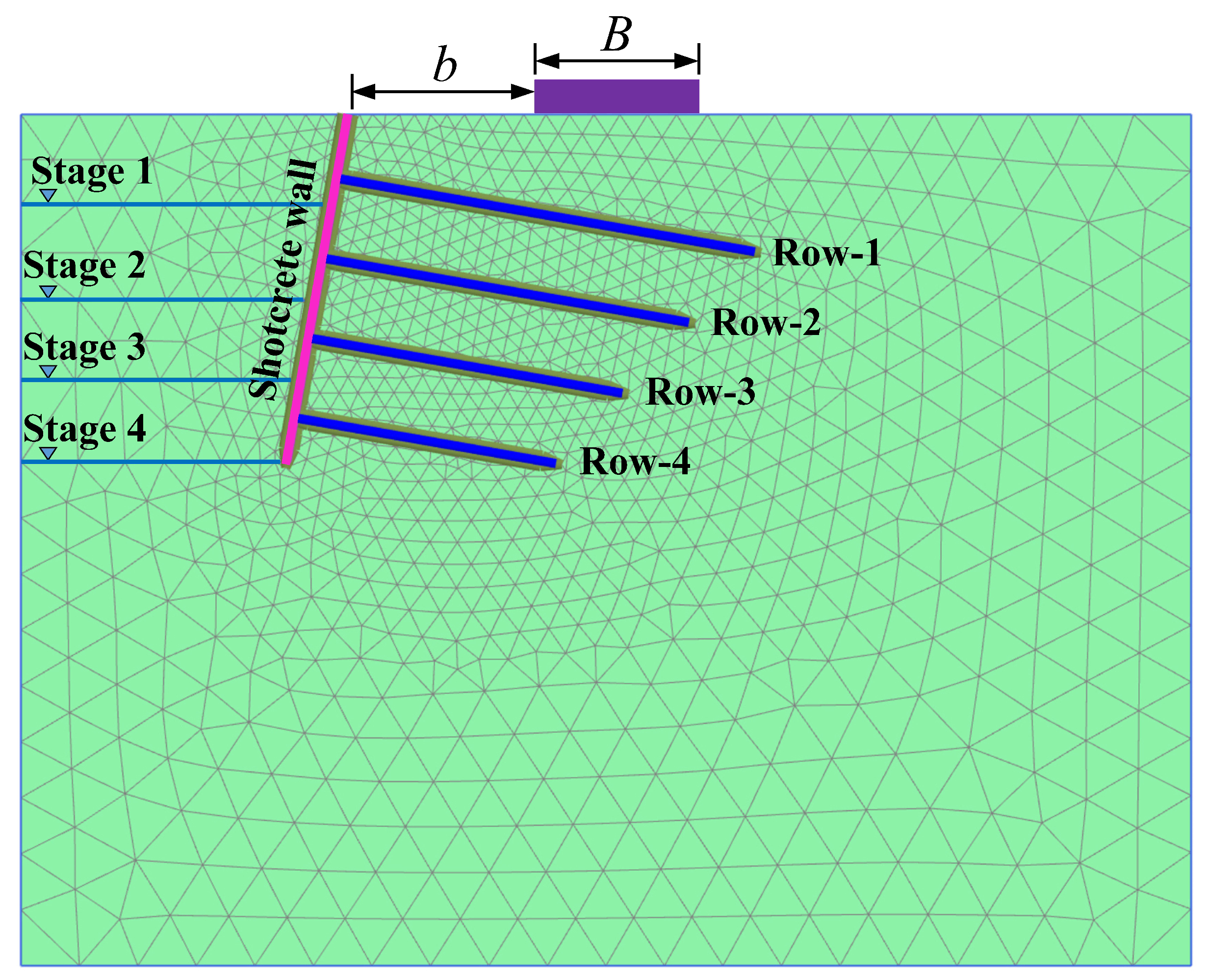
This study was conducted using the finite element program Plaxis 2D. The simulated model was a plain-strain model 22 m wide and 16 m high, sufficient to minimize the numerical result from any boundary effect [21]. The left and right boundaries of the mesh are allowed to move only in a vertical direction, while the bottom boundary is fixed in both of its vertical and horizontal directions. The fine mesh used in the model was made up of 15-noded triangular elements (Figure 1).
2.1. Materials’ Properties
The soil was represented by an isotropic, homogeneous, elastic–perfectly plastic material, which obeys the Mohr–Coulomb failure criterion. Singh and Babu [19] found that the use of the Mohr–Coulomb model in soil-nailing simulation is reasonably safe compared with other advanced soil models, such as the HS (hardening-soil) model and the HS-small (hardening-soil with small strain stiffness) model, because the Mohr–Coulomb model over-estimated the lateral displacements of the soil-nailing wall up to 60% of the construction stage and basal heave at the end of the excavation process [19,22].
The nail and shotcrete wall were represented by plate structural elements [9,19,23] and modeled as elastic materials because of the high ultimate bonding strength between steel reinforcement and cement grout [24,25] and the low yielding possibility [26]. The plate is continuous in the out-of-plane direction. A zero-thickness interface element represented the interface between the grout and the soil. Elahi et al. [7], Rawat and Gupta [27], and Jaiswal and Chauhan [28] used an interface with a thickness of 0.1 mm in their studies. The roughness or the strength of the soil/grout interface is defined by the strength reduction coefficient , which can be calculated as
where and are the apparent cohesion and frictional angle of the soil, respectively, whereas and are the cohesion and friction angle of the soil/grout interface, respectively. In this study, the value of the interface coefficient has been taken as 2/3 [9]; of 1.0 is used when the interface between the soil and the grout is perfectly rough, while of 0.0 is used when the soil and grout interface is perfectly smooth.
The safety factor (FOS) against sliding was also calculated to quantify the stability condition of the nail-supported excavation for each factor considered in this study. The limit equilibrium method is commonly employed to determine the FOS from the ratio of the resisting and the driving forces (or moments) acting on the critical sliding surface, assuming that the driving and resisting forces do not depend on displacement [29,30,31]. This assumption is called perfectly plastic behavior, in which the strength does not change even after slope failure.
The FOS in Plaxis is computed using the so-called reduction method or shear strength reduction method (SRM) [32]. In this method, the initial strength parameters are reduced until the slope fails, generating a value defined as the incremental multiplier, ; as a result, the incremental multiplier converges when the slope fails. The ratio of the available strength to the critical stress at failure is also defined as FOS [7,33,34]:
The groundwater effect has yet to be included in this study as the water table is located 10 m below the excavation pit. In the absence of a groundwater table, there will be no excess pore-water pressure generated [9,19,27,35]; hence, a drain analysis has been performed throughout this study.
The “FHWA Soil-Nailing Manual” [36,37] provides the specifications, standards, and design parameters for designing soil-nailed retaining structures. Here, the homogeneous soil, which is silty clay, has a unit weight of 17.9 kN/m3. Its apparent cohesion and internal friction angle are 20 kPa and 15°, respectively; the Young’s modulus and the Poisson’s ratio of the soil are 12 MPa and 0.3, respectively. The nail reinforcement’s diameter, yield strength, and elastic modulus were derived from [20]. In contrast, the elastic modulus of concrete and grout was similar to the values given in [19]. These parameters are presented in Table 1.
2.2. Axial Stiffness and Flexural Rigidity of Nail and Shotcrete Wall
For the modeling of nails and shotcrete walls, the plate element was used in Plaxis. Due to their discrete nature, nails were modeled using an equivalent-plate-model approach [19,23,35], in which the axial stiffness and flexural rigidity are computed as
where is the nails’ horizontal spacing, is the drilled hole diameter, and is the equivalent elastic modulus, which contributes to the elastic stiffness for nail reinforcement and grouted cover of nails [9,19]; the equivalent elastic stiffness can be computed by
where and are the elastic moduli of the nail and grout, respectively; A is the cross-sectional area of the grouted nail ; is the cross-section area of bar reinforcement with diameter d; and is the cross-sectional area of grouted cover, which is given by .
2.3. Excavation Stages
The excavation and installation process of the nail-supported excavation pit can be numerically simulated. Excavation is simulated by deactivating the soil layer, while nails and shotcrete wall installation are simulated by activating the structural elements in the model. The ground initial stress was applied to the numerical model after generating the 2D mesh.
The 6.53-m-deep excavation and installation of nails and shotcrete walls were conducted in four stages, where the depth of each excavation thickness was maintained as closely as possible, i.e., roughly 1.50 m deep. Details for the construction sequence in each of the four excavation stages and the installation of the structural nail and wall elements are summarized in Table 2.
3. Results and Discussion
3.1. Effect of Excavation Stage
The foundation pit was excavated in four stages to a depth of 6.53 m below the ground surface, and the responses of the nail-supported excavation pit during each of these excavation stages have been observed. The thickness of the shotcrete wall was 100 mm, and there was no surcharge loading on the crest of the excavation pit. Excavation stages were simulated by deactivating the soil clusters, while the nails and shotcrete wall installation were modeled by activating the nails and the wall structural elements, respectively. The responses of the nail-supported excavation pit were recorded in terms of the nail axial (tensile) force, shotcrete wall horizontal deflection profile, global safety factor against sliding (FOS), and basal heave.
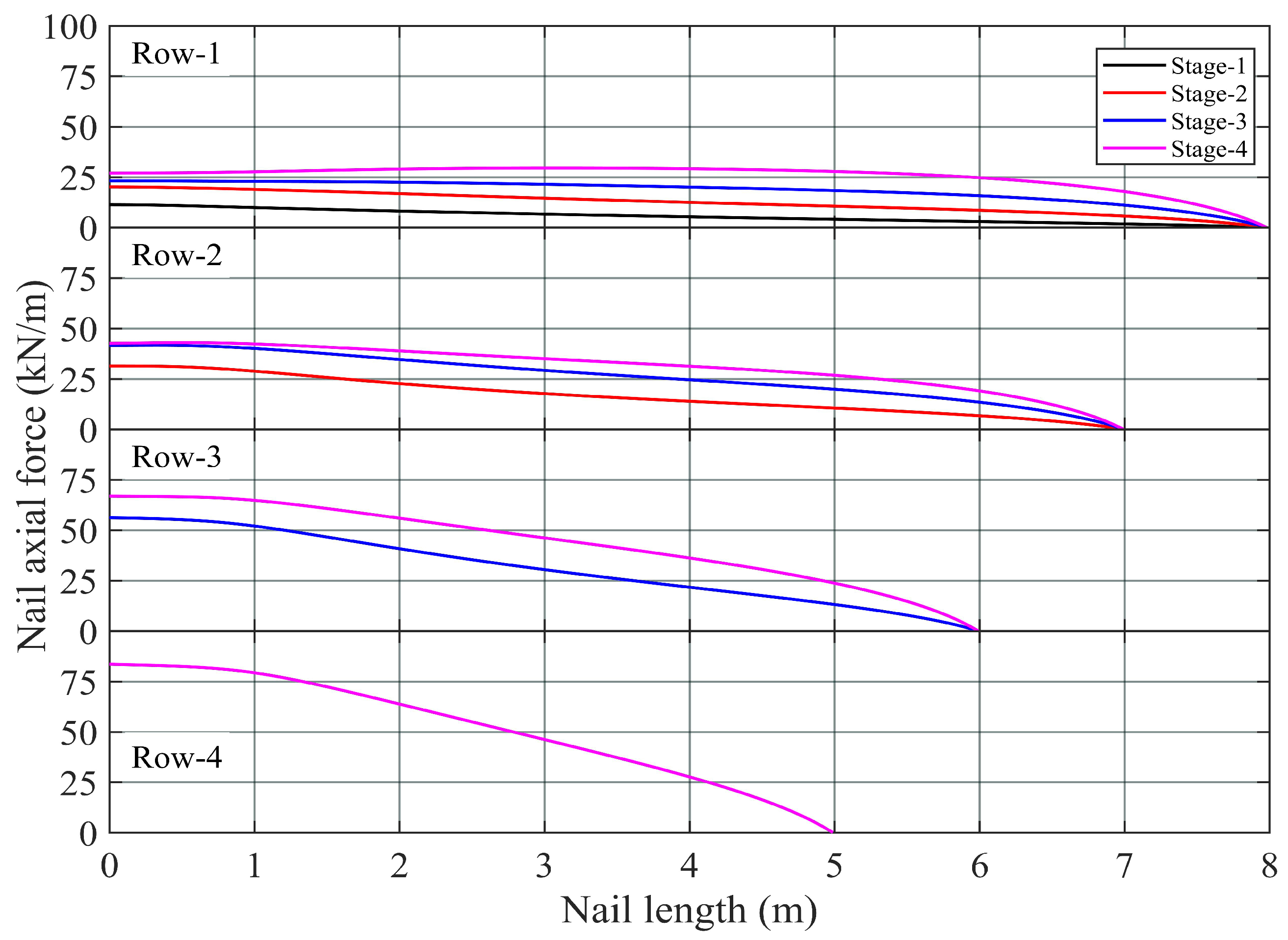
Figure 2 presents the axial force distribution along all of the nails during each excavation stage. The result shows that the axial force of the nail increases with the excavation stages and depth. For instance, the axial force in the Row-1 nail was lowest (11.4 kN/m) at the end of the first excavation stage but gradually attained a higher force (29.5 kN/m) at the end of the fourth excavation stage. In addition, among the forces in the four rows of the nail, the minimum force of 29.5 kN/m was observed in the first row (Row-1) nail, while the maximum force of 83.6 kN/m was observed in the last row (Row-4) nail at the end of all the excavation stages.
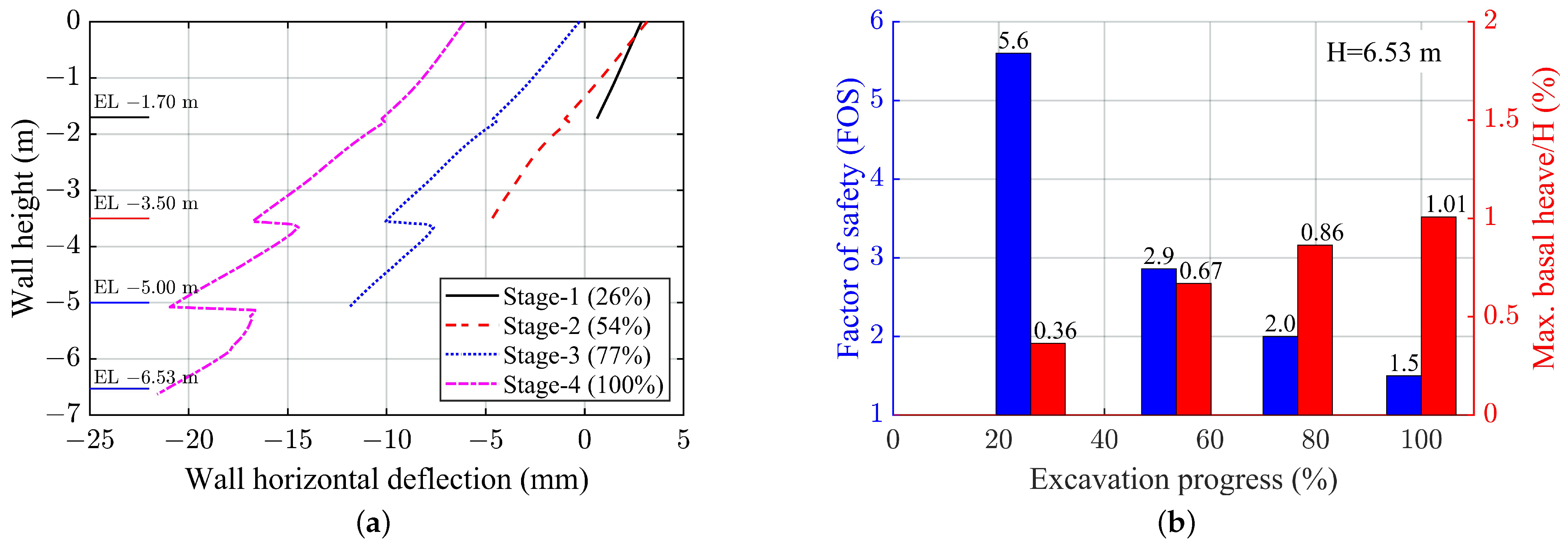
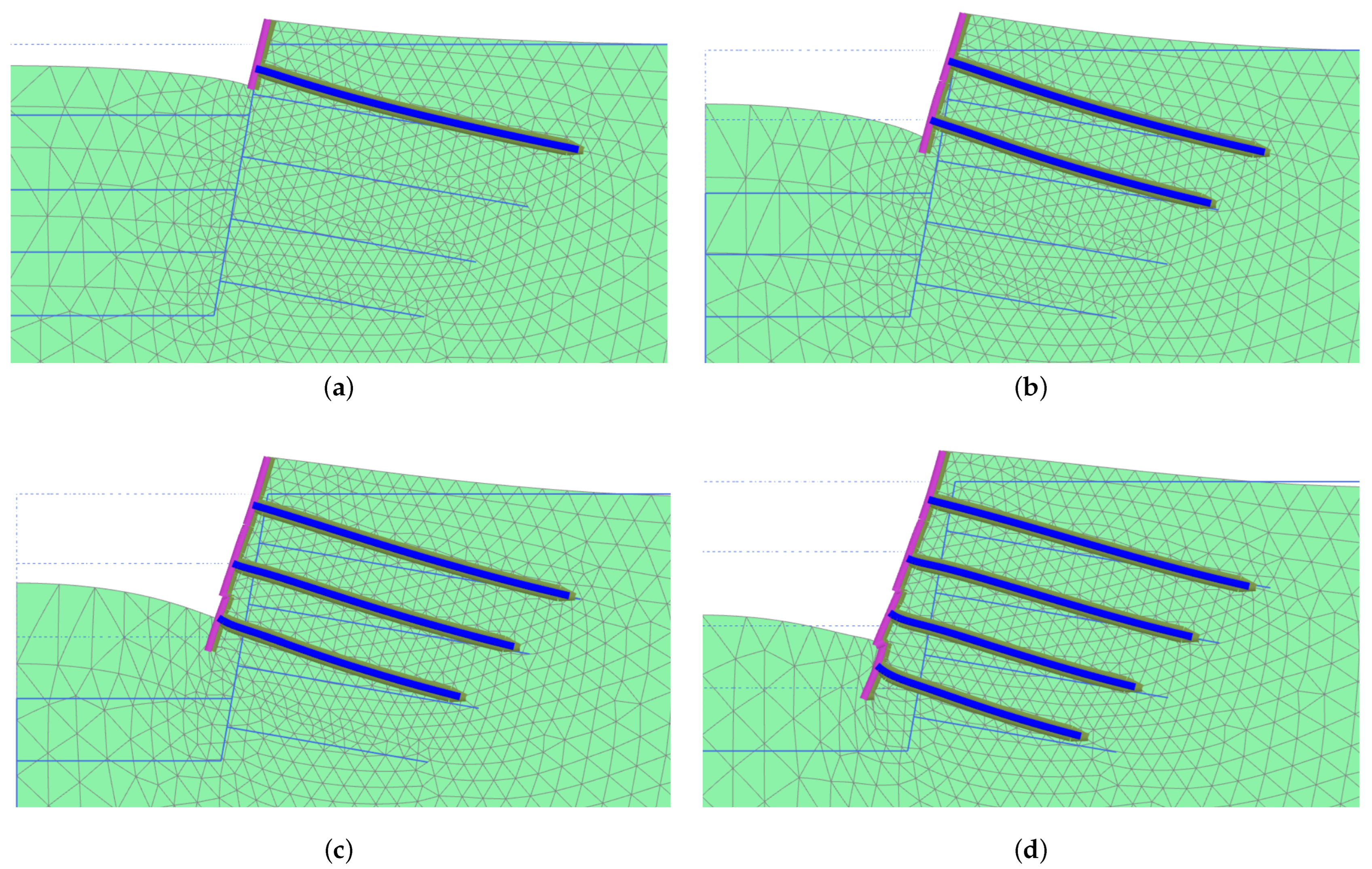
The horizontal deflection of the shotcrete wall during the excavation process is plotted in Figure 3a. The results reveal that the horizontal deflection of the wall at different depths of the excavation increases progressively. In Stage-1 excavation, the value of the horizontal deflection of the shotcrete wall is positive (black line); this means that the wall was virtually being pulled backward by the nail reinforcement. Johari et al. [15], who studied an actual site construction problem using the random finite element method (RFEM) to obtain the indices of global stability, lateral displacement stability, tensile strength, and pullout resistance stability for their soil-nailing wall system, also observed the phenomenon but they gave no explanation. A careful examination revealed that the unexcavated soil behind the wall heaved upward and, thus, dragged both the nail and the wall upward and towards the unexcavated side (Figure 4a).
In Stage-2, where the excavation level reached EL −3.50 m, three-quarters of the shotcrete wall installed in the first stage still remained on the unexcavated side, Figure 3a and Figure 4b, but the shotcrete wall installed during this stage completely deflected outward towards the excavated side. It was not until Stage-3, where the excavation level reached EL −5.00 m, that the three panels of shotcrete wall deflected in the expected fashion (Figure 4c). The sudden decrease in the horizontal deflection at EL −3.50 m was because the top and bottom shotcrete walls were not connected in the analysis to reflect the actual construction on site.
The maximum wall horizontal deflection of 21.6 mm (Figure 3a and Figure 4d) has been observed in the final stage of the excavation, and it was found to coincide with the toe of the un-socketed wall. These results coincided with the results obtained by [5]; through the experimental study of nailed soil slope models in medium-dense sand, they observed that the horizontal movement of the slope face increases with the construction stage and also with the excavation depth, and that their maximum deflection occurred in the vicinity of the toe of the slope face. For loose sand, the maximum deflection happened in the middle third of the excavation depth [5].
The safety factor against sliding recorded after each excavation stage is presented in Figure 3b. As expected, the FOS reduces progressively with the excavation depth. In the first stage of excavation, the FOS was 5.60, but at the end of full-depth excavation, the FOS was reduced to 1.5, the minimum value required by most design codes. A similar result has also been obtained by [2].
It is vital to identify basal heave or bearing capacity failure as one of the external failure modes for soil-nail walls constructed in fine-grained soils. This happens because the shotcrete wall does not penetrate the ground below the excavation level. The unbalanced load from the unexcavated side may cause the base to heave and ultimately generate bearing capacity failure [19,36]. Figure 3b shows the amount of basal heave at the bottom of the excavation of each excavation stage. It was observed that after the first excavation stage, the base of the excavation heaved about 0.36% of H, and at the end of the fourth excavation stage, the basal heave increased to about 1.01% of H, where H is the full excavation depth, i.e., 6.53 m.
3.2. Effect of Footing Setback Distance
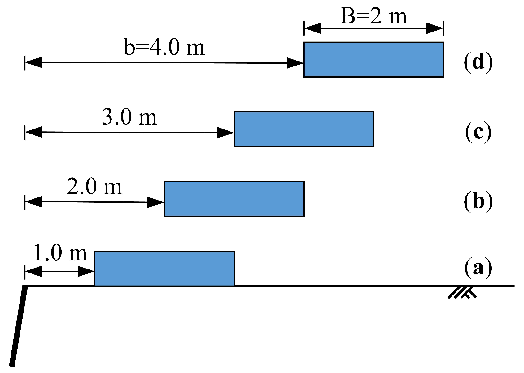
A two-meter-wide strip footing was placed at four different setback distances; the setback distance b is the distance between the cut face and the nearest edge of the strip footing (Figure 1 and Figure 5). The four setback distances considered in this study are 1 m, 2 m, 3 m, and 4 m, corresponding to a ratio of 1/2, 1, 3/2, and 2, respectively. The vertical surcharge loading considered was 30 kPa, and the thickness of the shotcrete wall was 100 mm.
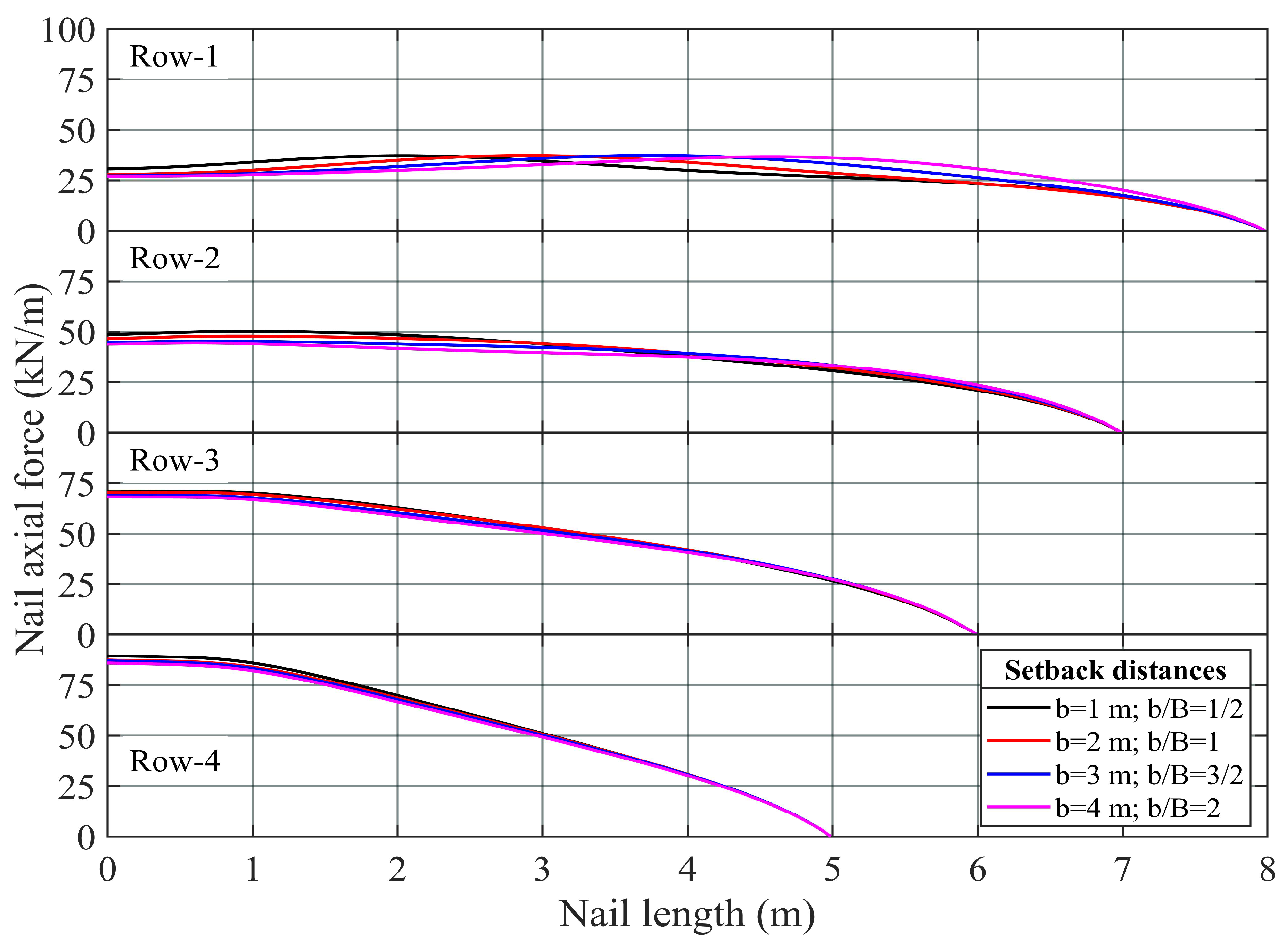
Figure 6 shows the distribution of the axial force of all the nail reinforcements; the result revealed that the distribution of the axial force in all the nails remained reasonably the same, except in the case of the Row-1 nail. For a particular setback distance, the maximum axial force in the Row-1 nail was found to be located directly beneath the corresponding strip footing. For each specific row of nails, the variation between the maximum and minimum axial forces among the four setback distances was at most 10% (Table 3). Another observation is that the axial force in the nail head decreases, albeit only slightly, as the setback distance increases; the decreases in nail head forces revealed that the nail head was undergoing stress relaxation when the footing was further away from the excavation face.
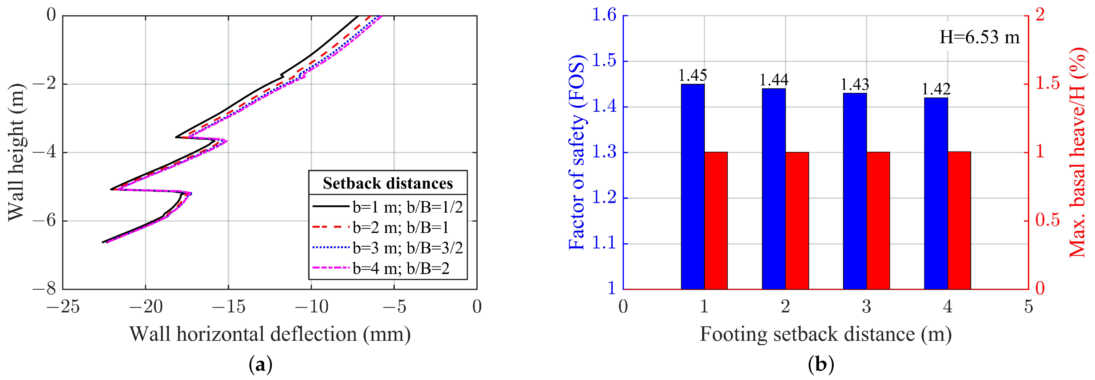
Figure 7a presents the result of the horizontal deflection of the shotcrete wall generated by footing with a 30 kPa surcharge and placed at various setback distances on the crest of the excavation pit. The maximum horizontal deflection profile was generated by the footing placed at a setback distance of 1 m; the horizontal deflection produced by the footing at setback distances of 2 m, 3 m, and 4 m does not seem to deviate too much. The setback distance effect is reduced with depth, approximately, until EL −3.70 m, i.e., to a depth of about twice that of the footing width at any point; after that, all four horizontal deflection profiles remain almost the same. Thus, footings with setback distances equal to or larger than 2 m seemed to have no significant effect on the horizontal deflection of the wall.
Figure 7b shows the result of the safety factor against sliding (FOS) concerning the four setback distances. The result indicates that the FOS only slightly reduces from 1.45 to 1.42 when the footing setback distance is increased from 1 m to 4 m. When the footing is placed in the vicinity (b = 1 m) of the shotcrete wall, full development of a sliding plane is impossible. However, when the footing is placed further away from the excavated face, the development of a complete sliding plane is permitted and, thus, results in a lower value of FOS. As for the basal heave, since the influence of the footing is until EL −3.70 m, the maximum basal heave of 1% of H shown in Figure 7b was purely due to the unloading of the topsoil; thus, the magnitude of the maximum basal heave remained unchanged for all four setback distances.
3.3. Effect of Strip Footing Width
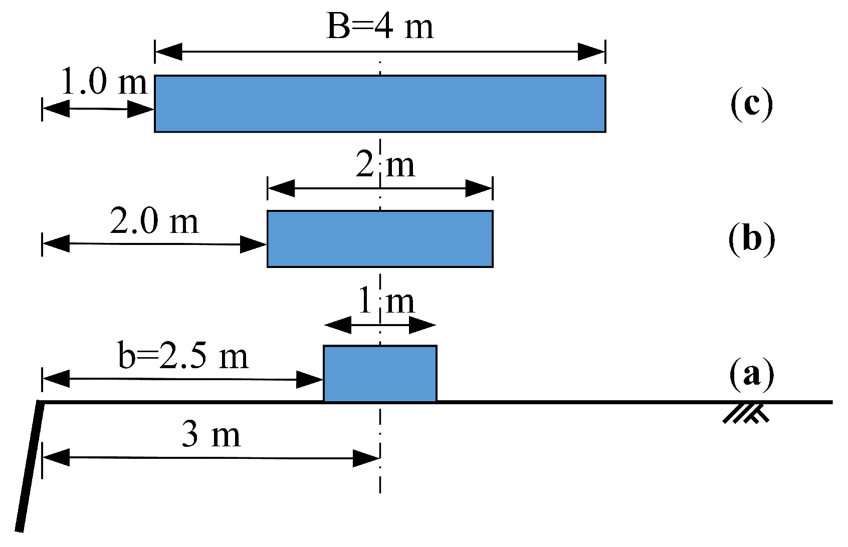
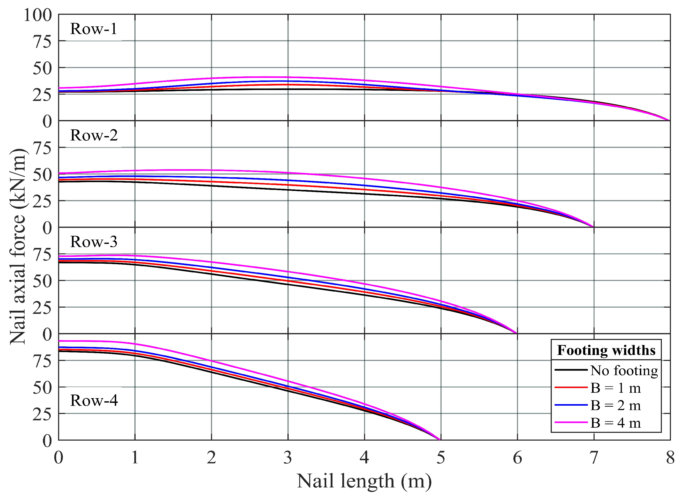
The effect of strip footing width on the response of nail-supported excavation is examined by considering footing with three different widths: 1 m, 2 m, and 4 m. The strip footings were placed with their center line measured at 3 m from the crest of the cut face (Figure 8). Thus, the setback distances would also be different. A 30 kPa vertical loading was applied to all the strip footings, and the thickness of the nailed shotcrete wall was kept at 100 mm.
Figure 9 shows the distribution of the nail axial force concerning different footing widths; the results revealed that the nail axial force is affected by the footing width, in which the more extensive the footing width, the more prominent the nail axial force is. Comparing the maximum axial force between the cases of no footing (without vertical load) and 4-m-wide footing (Table 4), the axial force in the Row-1 nail increased by almost 40% in the latter case. However, the maximum axial force deviation between these two cases reduces as the nail embedment depth increases. In addition, it was observed that, except for the nail in Row-1, where the maximum axial force was seen to mobilize directly beneath the footing, the maximum value of the axial force for the rest of the nails occurred at the rigid joint between the nail and the shotcrete wall.
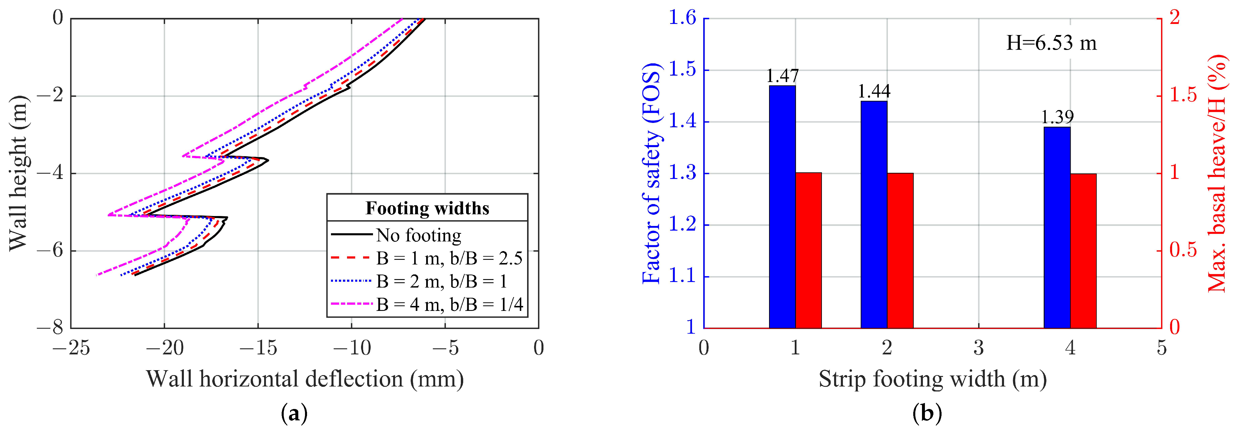
Figure 10a shows the deflection result of the shotcrete wall concerning footing width; the results show that the wall deflection increases as the width of the footing increases, as more load is transmitted to the retained ground. The maximum deflection of 23.6 mm was recorded at the final excavation level, i.e., 6.53 m, and when the footing was 4 m wide. Figure 10b presents the value of the global safety factor against sliding of the excavation pit. As reflected in the result of the horizontal wall deflection, the value of the FOS decreases with the increase in the footing width. That is to say, the value of the FOS is inversely proportional to the footing width. The maximum basal heave observed was 1% of H for all of the three footing widths (Figure 10b). Although the width of the strip footing plays an essential role in controlling the wall horizontal deflection, there is no additional heaving induced by the wider footing in this analysis.
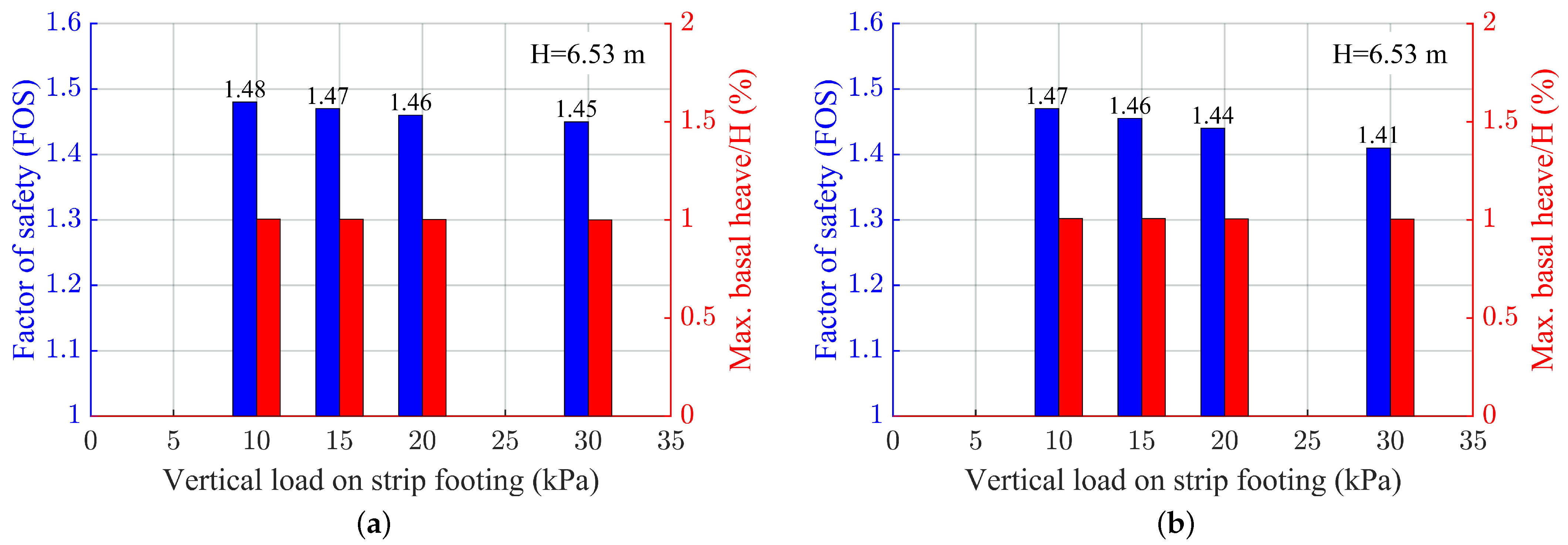
3.4. Effect of Vertical Load of Strip Footing
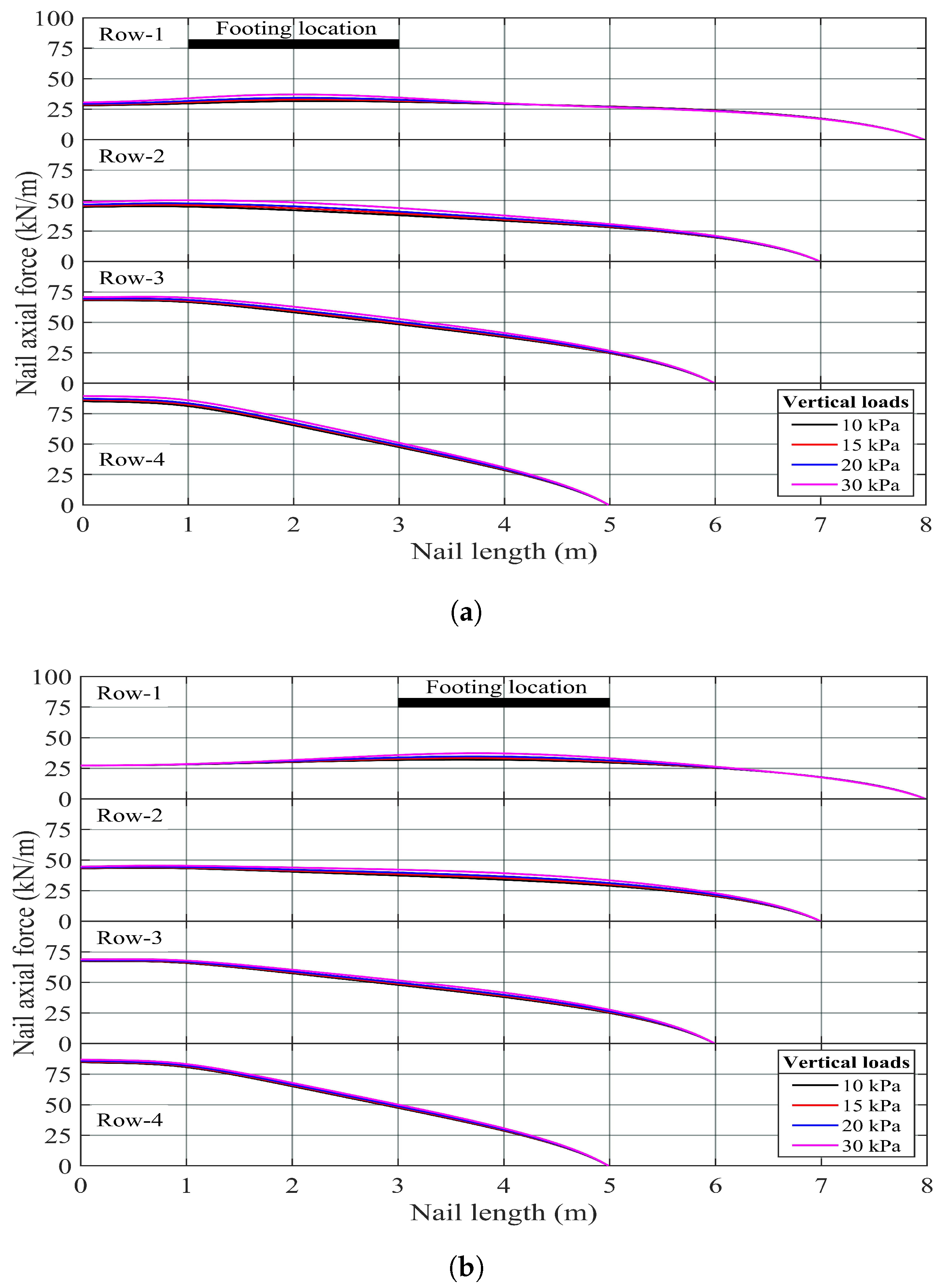
The effect of vertical load of strip footing on the responses of nail-supported excavation was studied by placing a 2-m-wide strip footing at setback distances of 1 and 3 m from the crest of the steeply inclined excavated face. The vertical load was activated at the end of Stage-4 excavation, assuming that the strip footing was to be loaded after the completion of all the excavation stages. The thickness of the shotcrete wall was 100 mm, while the vertical loads acting on the strip footing were 10 kPa, 15 kPa, 20 kPa, and 30 kPa.
Figure 11 shows the axial force distribution in all the installed nail reinforcements. The result shows that the vertical load has a negligible effect on the nail reinforcements’ axial force. The impact in the footing with a setback distance of 1 m (Figure 11a) is greater than that in the footing with a 3 m setback distance (Figure 11b), in which the effect is extended to the nail in the last row (Row-4) of the former case. It was observed from the result of the Row-1 nail (Figure 11a,b) that the vertical load on the footing induced extra-axial force in the nail portion directly beneath the footing. The nails in Row-3 and Row-4 of the footing with a setback distance of 3 m are, or almost are, outside the influence zone of the vertical load, resulting in very little or almost no additional axial force exerted in the final two rows of the nails.
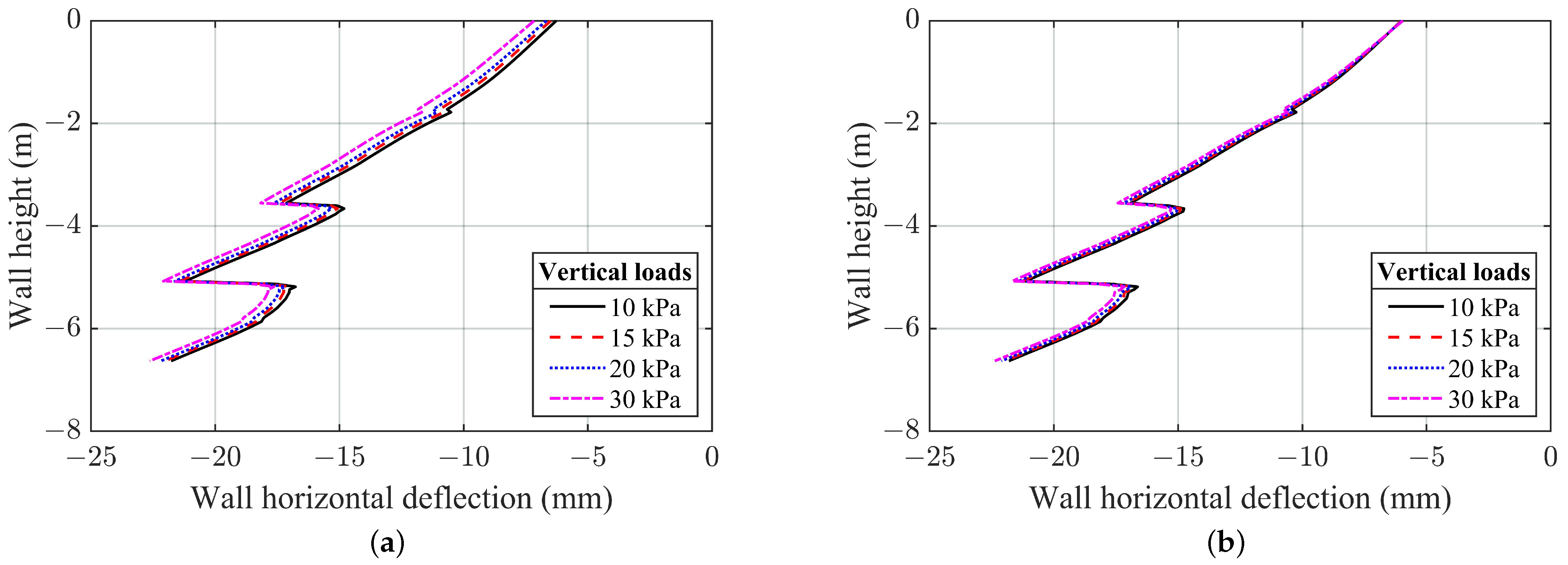
The horizontal deflection of the shotcrete wall is plotted in Figure 12. For the four vertical loads considered here, the effect of the vertical load of strip footing on the wall horizontal deflection is found to be more profound in the case of footing with a setback distance of 1 m than it is on that in footing with a setback distance of 3 m, Figure 12b. The variation between the deflection induced by the 10 kPa and 30 kPa vertical loads was 14% at the crest, but it gradually decreased to only 4% at the toe of the shotcrete wall, where the maximum wall deflection was observed.
The effect of vertical load of strip footing on the stability of the excavated pit, in terms of the safety factor (FOS), is presented in Figure 13. The result revealed that the stability of the excavated pit decreases as the vertical load increases. For the four vertical loads considered here, the FOS linearly decreases with increased footing loads. Wang et al. [38], who studied the effect of footing load on the stability of soil slopes, observed that for soil slopes of a 6 m, 8m, and 10 m height, the corresponding safety factor decreases linearly with the increase in loads from 0 to 40 kPa. As shown in the case of setback distance, the magnitude of the maximum basal heave remained unchanged for all of the four vertical loads studied here.
3.5. Effect of Soil/Grout Interface Roughness
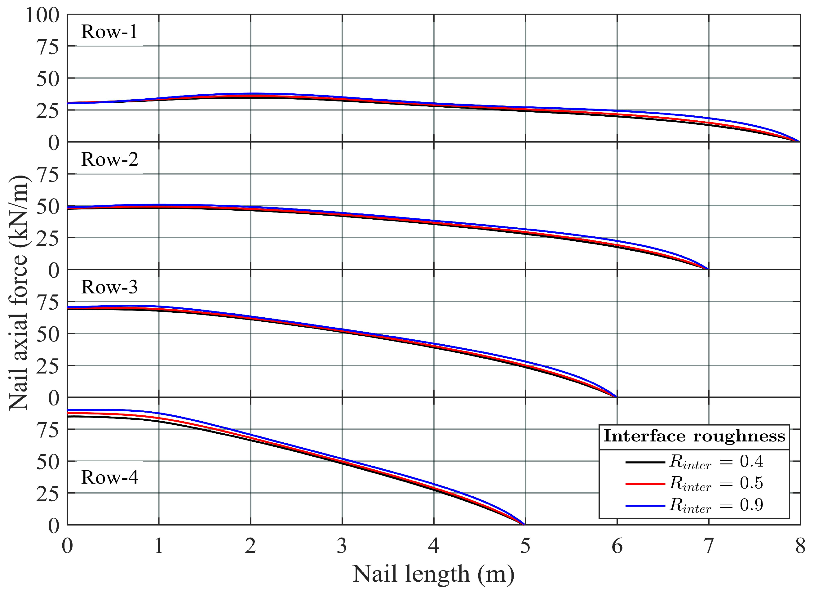
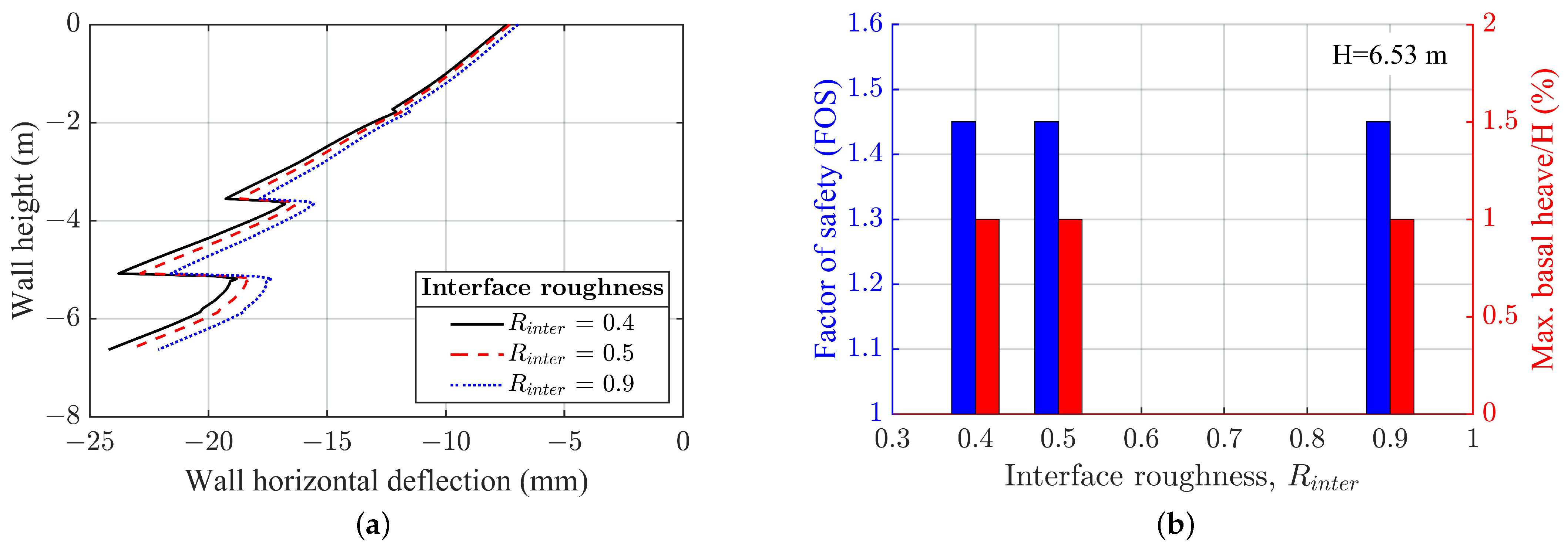
The performance of a reinforced soil structure depends on various factors in which the strength of the soil/reinforcement interface is one of the important governing parameters [39]. The performance of soil-nail-supported excavation could also be affected by the condition of the soil/grout interface. The study can be easily conducted by varying the strength or roughness of the interface coefficient in Plaxis. Three different values of , 0.4, 0.5, and 0.9, have been examined. A 30 kPa vertical loading was applied on the crest of the excavation pit, and the shotcrete wall thickness was kept at 100 mm.
The axial force distribution along all the nail reinforcements is presented in Figure 14; the result shows that the interface roughness coefficient has little effect on the nail axial force. The maximum nail force is recorded when the value of is 0.9, while the minimum force is observed when the value of is 0.4 for all of the four embedded nails in the model. This observation is plausible since the rougher the interface, the more load the nail can sustain. The observation corresponded to the finding of Yu and Bathurst [40], who have numerically studied the effect of the soil/geogrid interface on the pullout resistance of a geogrid via a numerical pullout test; they found that the interface only has a minor influence in the pullout load where the pullout load increases with the increase in the interface value.
Figure 15a shows the relation between the wall horizontal deflection and the interface coefficient ; it can be seen that the wall deflection decreases as the value of the interface coefficient increases. However, the effect of on the wall horizontal deflection is becoming more profound as the excavation depth increases, i.e., as the vertical stress increases. The variation of the horizontal deflections corresponds to the interface coefficients of increases of 0.4 and 0.9 from about 5.5% at the crest to about 10% at the toe level. However, Runser et al. [41], observing through a 17-m-high instrumented steel-strip-reinforced soil retaining wall, concluded that the soil/reinforcement friction was more fully mobilized in the upper half than the lower half of the reinforced mass, indicating that the mobilized apparent soil/reinforcement interface coefficient in the upper half of the reinforced mass is more significant than that in the lower half. The result of this study and that of Runser et al. [41] is consistent in the sense that the interface coefficient is not a constant but variable; as such, the value of used in the analysis should be a depth- or stress-dependent variable. Further investigation is needed to improve our understanding of the behavior of the soil/grout interaction when measuring, calculating, and designing the soil-nail-supported excavation.
Figure 15b presents the global safety factor against sliding and the maximum basal heave observed at the end of the excavation; however, both results were seen to be independent of the influence of soil/grout interface roughness.
4. Discussion: Theoretical Maximum Nail Force
The theoretical nail axial force can be computed as the product of horizontal active earth pressure at nail depth and the tributary area of the nail. According to Singh and Babu [19], a soil nail embedded at a depth z is subjected to an average active lateral pressure within an influence area bounded by the horizontal and vertical nail spacings. They used Equation (6) to derive their theoretical value of the maximum axial force of a nail embedded at depth z below the ground surface:
where is the coefficient of active earth pressure, given by Equation (7) [36]; is the unit weight of retained soil; and are the horizontal and vertical nail spacing, respectively. and form the tributary area of the nail.
However, their theoretical axial forces were found to be considerably greater than the axial forces computed by Plaxis. According to Singh and Babu [19], the reason that the numerical maximum axial forces were smaller than the theoretical maximum axial forces was that the theoretical axial forces did not take into consideration the load re-distribution due to the construction stage.
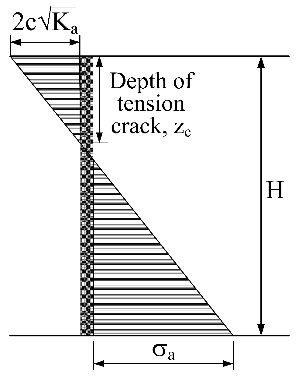
Strictly speaking, using Equation (7) may be inappropriate because Rankine’s formulation was derived from purely cohesionless material, but their analyses were conducted for a c- soil. For c- soil, tension cracks can form and considerably alter the active pressure (Figure 16); in this case, we may estimate the so-called apparent coefficient of active earth pressure using Equation (8) [42]:
where is the active earth pressure at the back of the wall at depth H, and is given by
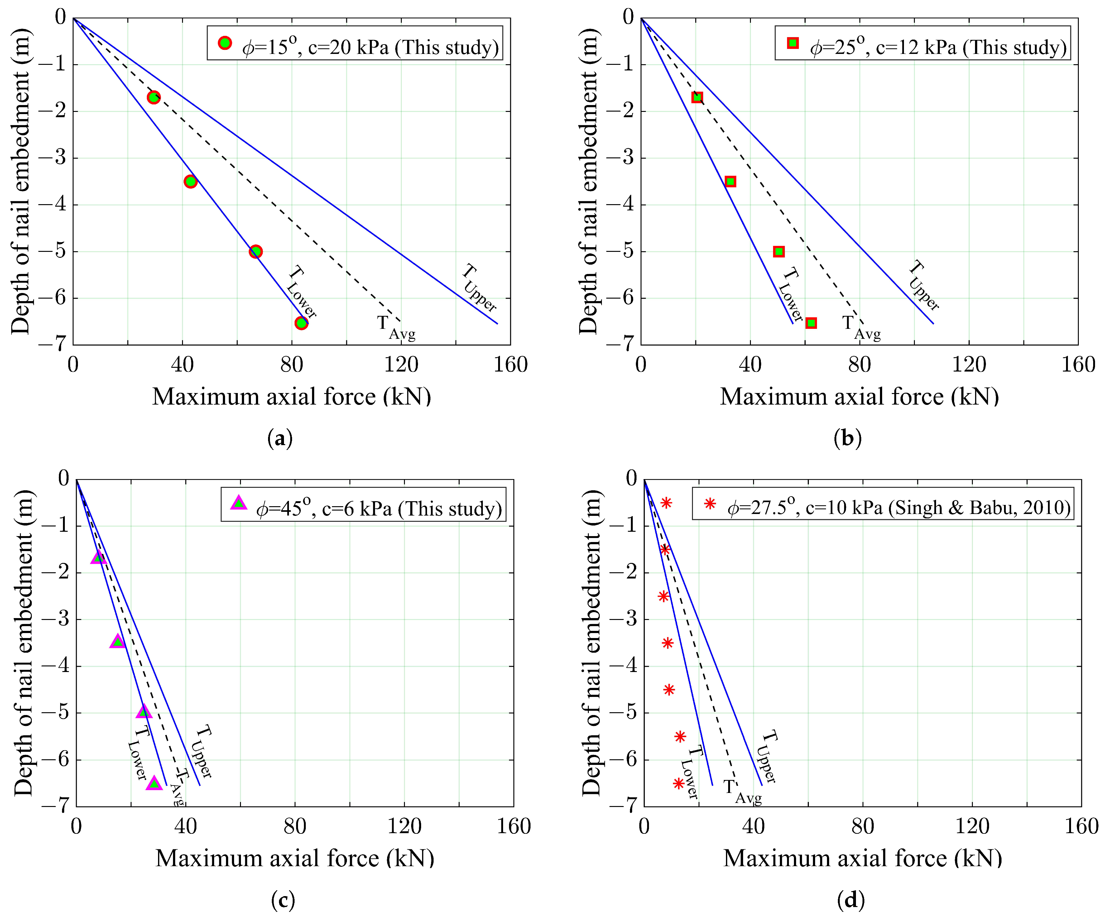
The maximum nail axial force mobilized at the end of Stage-4 excavation in each row (Figure 2) is plotted in Figure 17. The apparent cohesion and internal friction angle of the silty clay adopted in this study are 20 kPa and 15°, respectively. Firstly, without considering the tension crack, the coefficient of active earth pressure is 0.589; secondly, considering the tension crack and using Equations (7)–(9), the apparent coefficient of active earth pressure is 0.326. Figure 17a presents the theoretical value of the maximum axial forces derived from Equation (6). The value of in Equation (6) has been replaced by 0.589 and 0.326 to obtain the profiles and , respectively. In other words, the lower-bound theoretical maximum force is obtained by considering the presence of a tension crack. In contrast, the upper-bound theoretical maximum force is obtained by assuming that there is no tension crack. The maximum axial force numerically obtained from this study compared very well with the lower-bound theoretical maximum axial force (), which is obtained by replacing the in Equation (6) with the apparent coefficient of active earth pressure .
To better understand the relation between the theoretical and the numerical maximum axial forces, two additional analyses have been performed in soils with an internal friction angle and apparent cohesion of 25° and 12 kPa and 45° and 6 kPa, respectively. The maximum nail axial forces and their corresponding theoretical maximum nail axial forces are plotted in Figure 17b and Figure 17c, respectively. Again, the numerical maximum axial forces compared well with the lower-bound theoretical maximum axial forces. Finally, the numerical result presented by Singh and Babu [19] is plotted in Figure 17d, together with their theoretical maximum axial forces, . The theoretical maximum axial force underestimated the numerical value by 61% at the embedment depth of 0.5 m but over-estimated the numerical value by 236% at the embedment depth of 6.5 m. By considering the tension crack and, hence, adopting the apparent coefficient of active earth pressure to obtain the lower-bound theoretical maximum axial force , the outcome of the comparison can be significantly improved (Figure 17d).
From the above results, for an economical design of soil-nailing capacity, one may safely refer to the average value of the upper- and lower-bound of the theoretical maximum nail axial forces .
5. Conclusions
The behavior of soil-nail-supported excavation for a foundation pit has been studied through numerical simulations. Four rows of soil nails and 100-mm-thick shotcrete wall panels retained the steep excavated face. The effects of the stage excavation, vertical load on strip footing, footing setback distance from the excavation face, footing width, and roughness of the soil/grout interface on the behavior of the studied nail-supported excavation pit have been examined. The results were evaluated in terms of the axial force of nail reinforcement, wall horizontal deflection, safety factor against sliding, and basal heave. Based on the results obtained, the following conclusions have been drawn:
- The axial force in nail reinforcements continues to mobilize and increase as excavation progresses; the maximum axial force is observed in the Row-4 nail at the end of the entire excavation; the observation is plausible since the nail has to sustain more disturbance forces.
- The maximum axial force in c- soils is closely related to the apparent active earth pressure, which accounts for the presence of a tension crack, at nail depth.
- Among all the parameters studied, footing width is the most significant factor dominating the axial force of the nails, the wall horizontal deflection, and the safety factor against sliding. Using a wider strip footing undermined the stability of the nail-supported excavation pit.
- The horizontal deflection of the nail-supported wall is greatly affected by the 2-m-wide strip footing, which was loaded with a 30 kPa vertical load and placed at a setback distance of less than 2 m from the excavation face. However, the effect diminishes at depths greater than 2B (twice the footing width).
- The effect of the coefficient of the soil/grout interface on the nail axial force is minimal; however, it has significant impact on the wall horizontal deflection, especially at a deeper depth of the wall. The result indicates that a stress-dependent variable may best substitute the constant interface coefficient used in the numerical analysis.
- From the result of all the parameters studied, the resulting amount of basal heave remained at about 1% of the excavated depth, indicating that the configurations of the strip footing studied here, in particular, for a vertical load of 30 kPa or less, do not induce any additional effect on the base heaving.
- Although discernible wall horizontal deflection is observed in some of the parameters studied, the corresponding safety factor against sliding remained almost unchanged or decreased slightly. This is because the safety factor is calculated based on the shear strength reduction technique, which merely reduces the initial strength parameters until the slope fails; the technique does not depend on displacement.
This study did not consider the effect of soil anisotropy on the nail axial force, whereas a recent study by Zhang et al. [43] revealed that the axial force of the struts used in their braced excavation simulation increased by 50% due to soil anisotropy. More work on the theoretical evaluation of maximum axial force, in particular, that relates to the apparent active earth pressure is essential to better understand the mechanism of soil nailing in nail-supported excavation to allow engineers to assess and mitigate the risks of structural failure more effectively and optimize the design of nail-retaining structures.
Author Contributions
Conceptualization, R.P.R. and M.-W.G.; numerical analysis, R.P.R.; numerical data curation, R.P.R.; writing—original draft preparation, R.P.R.; writing—review and editing, M.-W.G.; supervision, M.-W.G. All authors have read and agreed to the published version of the manuscript.
Funding
This research received no external funding.
Data Availability Statement
The data presented in the study are included in the article, further inquiries can be directed to the authors.
Acknowledgments
We thank the three anonymous reviewers for taking the time and effort to review the manuscript. We sincerely appreciate all the insightful comments and suggestions that have helped us improve the quality of the manuscript.
Conflicts of Interest
The authors declare no conflict of interest.
Abbreviations
The following abbreviations are used in this manuscript:
| FEM | Finite element method |
| FHWA | Federal Highway Administration |
| FOS | Safety factor |
| LEM | Limit equilibrium method |
| SRM | Strength reduction method |
References
- Rawat, S.; Zodinpuii, R.; Manna, B.; Sharma, K.G. Investigation on failure mechanism of nailed soil slopes under surcharge loading: Testing and analysis. Geomech. Geoengin. 2014, 9, 18–35. [Google Scholar] [CrossRef]
- Liu, J.; Shang, K.; Wu, X. Stability analysis and performance of soil-nailing retaining system of excavation during construction period. J. Perform. Constr. Facil. 2016, 30, C4014002. [Google Scholar] [CrossRef]
- Pak, A.; Maleki, J.; Aghakhani, N.; Yousefi, M. Numerical investigation of stability of deep excavations supported by soil-nailing method. Geomech. Geoengin. 2021, 16, 434–451. [Google Scholar] [CrossRef]
- Mohamed, M.H.; Ahmed, M.; Mallick, J. Pullout behavior of nail reinforcement in nailed soil slope. Appl. Sci. 2021, 11, 6419. [Google Scholar] [CrossRef]
- Mohamed, M.H.; Ahmed, M.; Mallick, J. An experimental study of nailed soil slope models: Effects of building foundation and soil characteristics. Appl. Sci. 2021, 11, 7735. [Google Scholar] [CrossRef]
- Mohamed, M.H.; Ahmed, M.; Mallick, J.; AlQadhi, S. Finite element modeling of the soil-nailing process in nailed-soil slopes. Appl. Sci. 2023, 13, 2139. [Google Scholar] [CrossRef]
- Elahi, T.E.; Islam, M.A.; Islam, M.S. Parametric Assessment of Soil Nailing on the Stability of Slopes Using Numerical Approach. Geotechnics 2022, 2, 615–634. [Google Scholar] [CrossRef]
- Jayalekshmi, B.R.; Shivashankar, R. Numerical investigation on performance of nail stabilised vertical cuts. Mater. Today Proc. 2023. [Google Scholar] [CrossRef]
- Gui, M.-W.; Rajak, R.P. Responses of Structural Components of a Full-Scale Nailed Retaining Structure under the Influence of Surcharge Loading and Nail Head Configuration: A Numerical Study. Buildings 2023, 13, 561. [Google Scholar] [CrossRef]
- Gui, M.W.; Ng, C.W.W. Numerical study of nailed slope excavation. Geotech. Eng. 2006, 37, 1–12. [Google Scholar]
- Hossain, M.A.; Yin, J.H. Influence of grouting pressure on the behavior of an unsaturated soil-cement interface. J. Geotech. Geoenviron. Eng. 2012, 138, 193–202. [Google Scholar] [CrossRef]
- Sabermahani, M.; Nuri, H. Studying the effect of geometrical nail layout on the performance of soil-nailed walls: Physical and numerical modeling. Acta Geodyn. Geomater. 2021, 18, 45–59. [Google Scholar] [CrossRef]
- Wang, Q.; Ye, X.Y.; Wang, S.Y.; Sloan, S.W.; Sheng, D.C. Experimental investigation of compaction-grouted soil nails. Can. Geotech. J. 2017, 54, 1728–1738. [Google Scholar] [CrossRef]
- Ye, X.Y.; Wang, S.Y.; Wang, Q.; Sloan, S.W.; Sheng, D.C. Numerical and experimental studies of the mechanical behaviour for compaction grouted soil nails in sandy soil. Comput. Geotech. 2017, 90, 202–214. [Google Scholar] [CrossRef]
- Johari, A.; Hajivand, A.K.; Binesh, S.M. System reliability analysis of soil nail wall using random finite element method. Bull. Eng. Geol. Environ. 2020, 79, 2777–2798. [Google Scholar] [CrossRef]
- Rowe, R.K.; Ho, S.K. Horizontal deformation in reinforced soil walls. Can. Geotech. J. 1998, 35, 312–327. [Google Scholar] [CrossRef]
- Cheng, Z.H.; Deng, Y.S. Bearing Characteristics of Moso Bamboo Micropile-Composite Soil Nailing System in Soft Soil Areas. Adv. Mater. Sci. Eng. 2020, 2020, 3204285. [Google Scholar] [CrossRef]
- Dai, Z.H.; Gup, W.D.; Zheng, G.X.; Ou, Y.; Chen, Y.J. Moso bamboo soil-nailed wall and its 3D nonlinear numerical analysis. Int. J. Geomech. 2016, 16, 04016012. [Google Scholar] [CrossRef]
- Singh, V.P.; Sivakumar Babu, G.L. 2D numerical simulations of soil nail walls. Geotech. Geol. Eng. 2010, 28, 299–309. [Google Scholar] [CrossRef]
- Wang, H.; Cheng, J.; Li, H.; Dun, Z.; Cheng, B. Full-scale field test on construction mechanical behaviors of retaining structure enhanced with soil nails and prestressed anchors. Appl. Sci. 2021, 11, 7928. [Google Scholar] [CrossRef]
- Briaud, J.L.; Lim, Y.J. Soil-nailed wall under piled bridge abutment: Simulation and guidelines. J. Geotech. Geoenviron. Eng. 1997, 123, 1043–1050. [Google Scholar] [CrossRef]
- Brinkgreve, R.B.J.; Bakker, K.J.; Bonnier, P.G. The relevance of small-strain soil stiffness in numerical simulation of excavation and tunnelling projects. In Proceedings of the 6th European Conference in Geotechnical Engineering, Graz, Austria, 6–8 September 2006; Numerical Methods in Geotechnical Engineering. Schweiger, H.F., Ed.; Taylor & Francis: London, UK, 2006; pp. 133–139. [Google Scholar] [CrossRef]
- Babu, G.L.S.; Singh, V.P. Simulation of soil nail structures using PLAXIS 2D. Plaxis Bull. 2009, 25, 16–21. [Google Scholar]
- Hong, C.Y.; Yin, J.H.; Zhou, W.H.; Pei, H.F. Analytical study on progressive pullout behavior of a soil nail. J. Geotech. Geoenviron. Eng. 2012, 138, 500–507. [Google Scholar] [CrossRef]
- Kim, Y.; Lee, S.; Jeong, S.; Kim, J. The effect of pressure-grouted soil nails on the stability of weathered soil slopes. Comput. Geotech. 2013, 49, 253–263. [Google Scholar] [CrossRef]
- Zhou, Y.D.; Cheuk, C.Y.; Tham, L.G. Numerical modeling of soil nails in loose fill slope under surcharge loading. Comput. Geotech. 2009, 36, 837–850. [Google Scholar] [CrossRef]
- Rawat, S.; Gupta, A.K. Analysis of a nailed soil slope using limit equilibrium and finite element methods. Int. J. Geosynth. Ground Eng. 2016, 2, 34. [Google Scholar] [CrossRef]
- Jaiswal, S.; Chauhan, V.B. Influence of secondary reinforcement layers to enhance the stability of steep soil slope under earthquake loading. Arab. J. Geosci. 2022, 15, 1095. [Google Scholar] [CrossRef]
- Renani, H.R.; Martin, C.D. Factor of safety of strain-softening slopes. J. Rock Mech. Geotech. Eng. 2020, 12, 473–483. [Google Scholar] [CrossRef]
- Fredlund, D.G.; Krahn, J. Comparison of slope stability methods of analysis. Can. Geotech. J. 1977, 14, 429–439. [Google Scholar] [CrossRef]
- Zhou, X.P.; Cheng, H. Analysis of stability of three-dimensional slopes using the rigorous limit equilibrium method. Eng. Geol. 2013, 160, 21–33. [Google Scholar] [CrossRef]
- Brinkgreve, R.B.J.; Broere, W.; Waterman, D. Plaxis 2D—Version 8: Reference Manual; Delft University of Technology & Plaxis BV: Delft, The Netherlands, 2002. [Google Scholar]
- Fawaz, A.; Farah, E.; Hagechehade, F. Slope Stability Analysis Using Numerical Modelling. Am. J. Civ. Eng. 2014, 2, 60–67. [Google Scholar] [CrossRef]
- Lin, H.; Xiong, W.; Cao, P. Stability of soil nailed slope using strength reduction method. Eur. J. Environ. Civ. Eng. 2013, 17, 872–885. [Google Scholar] [CrossRef]
- Garzón-Roca, J.; Capa, V.; Torrijo, F.J.; Company, J. Designing soil-nailed walls using the Amherst wall considering problematic issues during execution and service life. Int. J. Geomech. 2019, 19, 05019006. [Google Scholar] [CrossRef]
- Lazarte, C.A.; Robinson, H.; Gómez, J.E.; Baxter, A.; Cadden, A.; Berg, R. Geotechnical Engineering Circular No. 7: Soil Nail walls—Reference Manual; Report No. FHWA-NHI-14-007; US Department of Transportation, Federal Highway Administration: Washington, DC, USA, 2015; 425p. Available online: https://www.fhwa.dot.gov/engineering/geotech/pubs/nhi14007.pdf (accessed on 22 May 2023).
- Taylor, T.P.; Collin, J.G.; Berg, R.R. Evaluation of Limit Equilibrium Analysis Methods for Design of Soil Nail Walls; Report No. FHWA-NHI-17-068; Federal Highway Administration: Washington, DC, USA, 2017; 56p. Available online: https://www.fhwa.dot.gov/engineering/geotech/pubs/nhi17068.pdf (accessed on 20 August 2023).
- Wang, Z.Y.; Zhang, W.G.; Gao, X.C.; Liu, H.L.; Böhlke, T. Stability analysis of soil slopes based on strain information. Acta Geotech. 2020, 15, 3121–3134. [Google Scholar] [CrossRef]
- Anubhav; Basudhar, P.K. Interface behavior of woven geotextile with rounded and angular particle sand. J. Mater. Civ. Eng. 2013, 25, 1970–1974. [Google Scholar] [CrossRef]
- Yu, Y.; Bathurst, R.J. Influence of selection of soil and interface properties on numerical results of two soil–geosynthetic interaction problems. Int. J. Geomech. 2017, 17, 04016136. [Google Scholar] [CrossRef]
- Runser, D.J.; Fox, P.J.; Bourdeau, P.L. Feild performance of a 17 m-high reinforced soil retaining wall. Geosynth. Int. 2001, 8, 367–391. [Google Scholar] [CrossRef]
- Caltrans. Trenching and Shoring Manual; Department of Transportation, Office of Structure Construction, State of California: USA, 2011; 409p. Available online: https://dot.ca.gov/-/media/dot-media/programs/engineering/documents/structureconstruction/201906-sc-trenchingshoring-a11y.pdf (accessed on 20 October 2023).
- Zhang, W.G.; Hu, X.Y.; Zhang, R.H.; Chen, C.X.; Li, Y.Q.; Ye, W.Y.; Zhang, Z.C.; Chen, R.L. Numerical analysis of one-strut failure in deep braced excavation considering anisotropic clay behavior. J. Cent. South Univ. 2023, 30, 4168–4181. [Google Scholar] [CrossRef]
Figure 1.
Finite element mesh of the soil model (B = strip footing width, b = setback distance).

Figure 2.
Effect of excavation stage on nail axial force.

Figure 3.
Effect of excavation stage on (a) wall horizontal deflection; (b) safety factor and maximum basal heave.
Figure 3.
Effect of excavation stage on (a) wall horizontal deflection; (b) safety factor and maximum basal heave.

Figure 4.
Behavior of nails and shotcrete wall in (a) Stage-1; (b) Stage-2; (c) Stage-3; (d) Stage-4. (Magnified 50 times.)
Figure 4.
Behavior of nails and shotcrete wall in (a) Stage-1; (b) Stage-2; (c) Stage-3; (d) Stage-4. (Magnified 50 times.)

Figure 5.
Footing setback distances b considered in this study: (a) 1.0 m; (b) 2.0 m; (c) 3.0 m; (d) 4.0 m.
Figure 5.
Footing setback distances b considered in this study: (a) 1.0 m; (b) 2.0 m; (c) 3.0 m; (d) 4.0 m.

Figure 6.
Effect of footing setback distance on nail axial force.

Figure 7.
Effect of footing setback distance on (a) wall horizontal deflection; (b) safety factor and maximum basal heave.
Figure 7.
Effect of footing setback distance on (a) wall horizontal deflection; (b) safety factor and maximum basal heave.

Figure 8.
Layout of footing width B considered in this study: (a) 1.0 m; (b) 2.0 m; (c) 4.0 m.

Figure 9.
Effect of footing width on nail axial force.

Figure 10.
Effect of footing width on (a) wall horizontal deflection; (b) safety factor and maximum basal heave.
Figure 10.
Effect of footing width on (a) wall horizontal deflection; (b) safety factor and maximum basal heave.

Figure 11.
Effect of vertical load of strip footing on nail axial force, for (a) footing with a setback distance b of 1 m; and (b) footing with a setback distance b of 3 m.
Figure 11.
Effect of vertical load of strip footing on nail axial force, for (a) footing with a setback distance b of 1 m; and (b) footing with a setback distance b of 3 m.

Figure 12.
Effect of a vertical load of strip footing on wall horizontal deflection, for (a) footing with a setback distance b of 1 m; and (b) footing with a setback distance b of 3 m.
Figure 12.
Effect of a vertical load of strip footing on wall horizontal deflection, for (a) footing with a setback distance b of 1 m; and (b) footing with a setback distance b of 3 m.

Figure 13.
Effect of a vertical load of strip footing on the safety factor, for (a) footing with a setback distance b of 1 m; and (b) footing with a setback distance b of 3 m.
Figure 13.
Effect of a vertical load of strip footing on the safety factor, for (a) footing with a setback distance b of 1 m; and (b) footing with a setback distance b of 3 m.

Figure 14.
Effect of soil/grout interface roughness on nail axial force.

Figure 15.
Effect of soil/grout interface roughness on (a) wall horizontal deflection; (b) safety factor and maximum basal heave.
Figure 15.
Effect of soil/grout interface roughness on (a) wall horizontal deflection; (b) safety factor and maximum basal heave.

Figure 16.
Active earth pressure distribution for cohesive soil.

Figure 17.
Theoretical and numerical maximum nail axial force in c- soils for cases without vertical load: (a) , kPa; (b) , kPa; (c) , kPa; (d) , kPa.
Figure 17.
Theoretical and numerical maximum nail axial force in c- soils for cases without vertical load: (a) , kPa; (b) , kPa; (c) , kPa; (d) , kPa.


Table 1.
List of soil-nail and shotcrete wall parameters used in the numerical simulation.
| Parameter | Value |
|---|---|
| Material model | Elastic |
| Yield strength of reinforcement (MPa) | 415 |
| Elastic modulus of reinforcement (GPa) | 200 |
| Elastic modulus of shotcrete wall (GPa) | 34.5 |
| Elastic modulus of grout (GPa) | 22 |
| Diameter of reinforcement d (mm) | 20 |
| Drill hole diameter (mm) | 120 |
| Length of nails (m) | 5, 6, 7, 8 |
| Nails’ inclination (degree) | 10 |
| Horizontal and vertical spacings of nail (m) | 1.5 |
| Thickness of shotcrete wall t (mm) | 100 |
| Coefficient of interface |
Table 2.
Details of excavation stages and installation of structural nail and wall elements.
| Stage/Nail Row No. | Excavation Level | Nail Installation Level | Shotcrete Wall Installation |
|---|---|---|---|
| 1 | EL −1.70 m | EL −1.20 m | EL 0.0 m to EL −1.70 m |
| 2 | EL −3.50 m | EL −2.70 m | EL −1.70 m to EL −3.50 m |
| 3 | EL −5.00 m | EL −4.20 m | EL −3.50 m to EL −5.00 m |
| 4 | EL −6.53 m | EL −5.70 m | EL −5.00 m to EL −6.53 m |
Table 3.
Maximum axial force in each nail under different footing setback distances.
| Max. Axial Force (kN) | Setback Distance | Maximum | |||
|---|---|---|---|---|---|
| Nail in | 1 m | 2 m | 3 m | 4 m | Variation % |
| Row-1 | 37.1 | 37.2 | 37.2 | 36.6 | 1.4 |
| Row-2 | 50.2 | 47.9 | 45.4 | 45.3 | 9.8 |
| Row-3 | 71.0 | 70.4 | 68.9 | 68.2 | 3.9 |
| Row-4 | 89.5 | 87.3 | 86.9 | 85.9 | 4.0 |
Table 4.
Maximum axial force in each nail under different footing widths.
| Max. Axial Force (kN) | Footing Width | Maximum | |||
|---|---|---|---|---|---|
| Nail in | No Footing | 1 m | 2 m | 4 m | Variation % |
| Row-1 | 29.5 | 33.8 | 37.2 | 40.9 | 38.6 |
| Row-2 | 43.0 | 45.2 | 47.9 | 53.7 | 24.8 |
| Row-3 | 66.8 | 68.4 | 70.4 | 73.6 | 10.2 |
| Row-4 | 83.6 | 85.2 | 87.3 | 93.3 | 11.6 |
Disclaimer/Publisher’s Note: The statements, opinions and data contained in all publications are solely those of the individual author(s) and contributor(s) and not of MDPI and/or the editor(s). MDPI and/or the editor(s) disclaim responsibility for any injury to people or property resulting from any ideas, methods, instructions or products referred to in the content. |
© 2024 by the authors. Licensee MDPI, Basel, Switzerland. This article is an open access article distributed under the terms and conditions of the Creative Commons Attribution (CC BY) license (https://creativecommons.org/licenses/by/4.0/).
Share and Cite
MDPI and ACS Style
Gui, M.-W.; Rajak, R.P. A Numerical Study of a Soil-Nail-Supported Excavation Pit Subjected to a Vertically Loaded Strip Footing at the Crest. Buildings 2024, 14, 927. https://0-doi-org.brum.beds.ac.uk/10.3390/buildings14040927
AMA Style
Gui M-W, Rajak RP. A Numerical Study of a Soil-Nail-Supported Excavation Pit Subjected to a Vertically Loaded Strip Footing at the Crest. Buildings. 2024; 14(4):927. https://0-doi-org.brum.beds.ac.uk/10.3390/buildings14040927
Chicago/Turabian StyleGui, Meen-Wah, and Ravendra P. Rajak. 2024. "A Numerical Study of a Soil-Nail-Supported Excavation Pit Subjected to a Vertically Loaded Strip Footing at the Crest" Buildings 14, no. 4: 927. https://0-doi-org.brum.beds.ac.uk/10.3390/buildings14040927
Note that from the first issue of 2016, this journal uses article numbers instead of page numbers. See further details here.