
Influence of Staggered Truss on Progressive Collapse-Resistant Behavior of Steel Frame Structures

School of Civil Engineering, Architecture and Environment, Hubei University of Technology, Wuhan 430068, China
*
Author to whom correspondence should be addressed.
Buildings 2024, 14(4), 931; https://0-doi-org.brum.beds.ac.uk/10.3390/buildings14040931
Submission received: 3 March 2024
/
Revised: 26 March 2024
/
Accepted: 26 March 2024
/
Published: 28 March 2024
(This article belongs to the Special Issue Advances in Steel Structures: Testing, Modelling and Design)
Abstract
:In order to study the effect of the support mode of a staggered truss system on the continuous collapse resistance performance of a steel structure, four finite element models were established based on the bracing arrangement of a five-story steel frame structure. The situations of different columns on the first floor removed were classified into eight scenarios, and five models of each scenario were analyzed with nonlinear dynamic analyses. Finally, a computational metric based on energy robustness was proposed to evaluate the robustness of the structure. The results of nonlinear dynamic analyses indicated that the staggered truss system significantly improved the resistance to progressive collapse of steel frame structures and effectively increased the redundancy of steel frame structures. All four bracing methods effectively reduced the vertical displacement at the point of failure, with the peak displacement at the point of failure reduced by a maximum of 84 percent and a minimum of 41 percent compared to a pure frame structure. Moreover, the staggered truss system can reduce some axial force peaks in the adjacent columns adjacent to the failed columns. The structural robustness coefficients of Model A, Scheme 1, Scheme 2, Scheme 3, and Scheme 4 are 1.144, 1.339, 1.306, 1.584, and 1.176, respectively, according to the proposed robustness calculation method, which shows that the braced steel frame structure has improved robustness over the original structure. The staggered truss system improves the robustness of the steel frame structure so that the steel frame structure has better resistance to progressive collapse.
1. Introduction
Starting from the residential collapse of Ronan Point in London in 1968, more and more researchers in engineering circles began to pay attention to the problem of resistance to the progressive collapse of building structures. Many researchers have carried out in-depth analyses and research on this issue. Even more significant progress has been made in recent years. Foad et al. [1] summarized the parameters and reinforcement modification techniques that have impacts on structural strengthening strategies to mitigate the progressive collapse of structures. Ke et al. [2] proposed a sensitivity analysis method for evaluating the importance of planar truss structural units with the lower chord as the statistical object. Furthermore, based on identifying essential elements, targeted anti-progressive collapse design can improve the structure’s bearing capacity. The progressive collapse capacity of a multi-column frame tube structure was estimated by Zhao et al. [3] using the alternating load path method. It was obtained that 0.1 times the residual structure’s first-order vertical vibration modal period was reasonably taken. The dynamic amplification factor was set to 2.0 when the ALP method was used for the progressive collapse analysis. Anas et al. [4] summarized over twenty significant publications on the explosive responses of reinforced concrete floor slabs. Steel structures are widely used because of their lightweight and high-strength materials, high load-bearing capacity, high ductility, high toughness, fast construction speed, and short cycle time. It is of practical significance to study the resistance of steel structures to progressive collapse. Structural robustness is a way to quantify the overall solidity and resistance to the progressive collapse of a structure, and a structure with good robustness is one of the most important measures to prevent the progressive collapse of a structure. In order to improve the resistance to progressive collapses of steel frame structures, many researchers have proposed adding braces in steel frame structures, which are mainly divided into concentric braces and eccentric braces [5,6].
The staggered truss structure is a new type of lateral force-resisting system developed by the Massachusetts Institute of Technology in the 1960s with the investment of the U.S. Steel Corporation, which mainly consists of staggered trusses and frame structures [7]. This kind of structure has the advantages of low steel consumption, lightweight, and fast construction. This structure has been investigated and developed for many years. In 1969, Haroldet al. [8] initiated the design ideas and force transfer methods of a steel staggered truss system with an example of a senior apartment building with a steel staggered truss system. Several researchers then conducted a series of studies on this basis. Goel and Itani [9] removed one bay of the staggered truss structural system and performed calculations and analyses under repeated loads. Wahyuni and Tetho [10] analyzed and discussed the effect of the ratio of the length of the web intervals to the truss cell spacing on the seismic performance of staggered trusses. Kim and Lee [11] replaced the abdominal rods in staggered trusses with internal columns, buckling-restrained energy-consuming braces, or diagonal braces. They used the Pushover analytical method to simulate the nonlinear relationships between loads and displacements. In China, Zhou et al. [12,13,14] conducted a series of analyses and research on this structure. Zhou et al. [15] analyzed the synergistic force model and proposed a staggered truss system’s displacement and internal force calculation formula under horizontal loads. Zong et al. [16] used the energy method to design a staggered truss system with better resistance to seismic effects.
Most of the research on staggered truss systems focuses on seismic performance and force performance but less on their resistance to vertical progressive collapse and robustness [17,18,19]. Moreover, improving the resistance of steel structures, as one of the most frequently used building structures, to progressive collapse has been the focus of researchers’ attention. Therefore, the staggered truss system is combined with the multi-story steel frame structure, and according to the literature [20], four kinds of staggered trusses with compartmentalized arrangements are designed for the bracing arrangement of the steel frame structure, and nonlinear dynamic analysis is carried out for the steel frame structure braced by the four kinds of staggered trusses with compartmentalized arrangements. In addition, this paper also proposes an energy-based robustness calculation metric to evaluate the robustness of the five structures, which also verifies the feasibility of the robustness assessment method proposed in this paper. In order to investigate the effect of this bracing on the resistance of steel frame structures to progressive collapse, this paper compares the resistance to progressive collapse of four braced steel structures with the original structure. Furthermore, the robustness of the five structures is evaluated, which also verifies the feasibility of the robustness assessment method proposed in this paper. This paper aims to provide a reference for optimizing the staggered truss structural system and the design of steel structure against progressive collapse.
2. Materials and Methods
2.1. Model Parameters
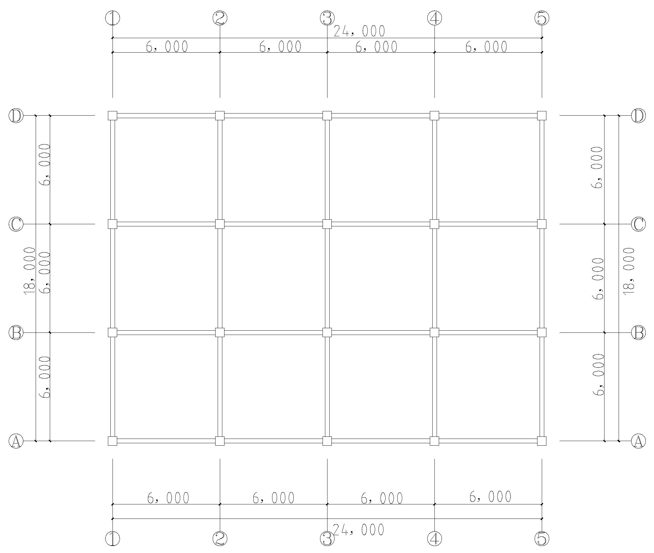
The model analyzed in this paper was a five-story steel frame structure with four horizontal spans with the column spacing of 6 m, three vertical spans with the column spacing of 6 m, and a story height of 4 m. The beam cross-section was HN350 × 175 × 7 × 11, the column cross-section was HW500 × 500 × 15 × 25, and the bracing cross-section was HN300 × 150 × 6.5 × 9. The components were all made of Q345 steel.
The dead load of the frame floor was 4.5 kN/, and the value of the live load effect (in this case, the floor live load and the roof live load) was taken as 2.5 kN/. Because the structure of this building was a multi-story frame, wind loads did not play a dominant role, so wind loads were not counted in the load combination [21]. These loads were converted to line loads arranged on the beam members at each level. PKPM 2010 V51 software (CAD software for architectural engineering design) was used to calculate the internal force and reinforcement of the unsupported steel frame structure, and the model was imported into SAP2000 21 software (General Building Structural Analysis and Design Software) after meeting the specification requirements, based on which four kinds of steel structure staggered truss systems were established. SAP2000 is a general-purpose building structure analysis and design software developed by CSI, USA. It integrates computational and analytical functions such as static force, modal, reaction spectrum, and time course analysis. It simulates structural components of various shapes and mechanical properties in frames, shells, solids, joints, suspension cables, planes, and other units. SAP2000 also includes many commonly used structural design codes, including the Chinese code, which can satisfy the structural design work in most areas. This paper focused on the effect of staggered truss bracings on the resistance of steel frame structures to progressive collapse, so the deformations of frame beams and frame columns were mainly considered. The effects of slabs and sub-beams on the structure were not considered. Floor slab calculations were complex in collapse analyses, and code UFC4-023-03 [22] adopted the method of commuting the floor slab loads into the beams. Following this principle, the weight of the floor slab was transferred to the corresponding beams by bi-directional slab transfer.
For frame units, SAP2000 provides four types of plastic hinges: moment hinges (M), shear hinges (V), axial force hinges (P), and compression bending hinges (P-M-M). One or more different plastic hinges can be arranged in the structure to match the plastic development of the members for different stress forms. In this paper, based on the force characteristics of the frames with braces, the arrangement of plastic hinges for each member followed the principles below. (1) The frame beams were only arranged with bending plastic hinges (M3) located at the ends of the beams at relative distances of 0.1 and 0.9, respectively. (2) The frame columns were arranged with axial force–moment composite plastic hinges (P-M2-M3) located at the ends of the columns at relative distances of 0.1 and 0.9, respectively. (3) The axial force was approximately equal at all positions during the regular support operation, and only the bending plastic hinge (M3) was arranged in the middle of the support at a relative distance of 0.5.
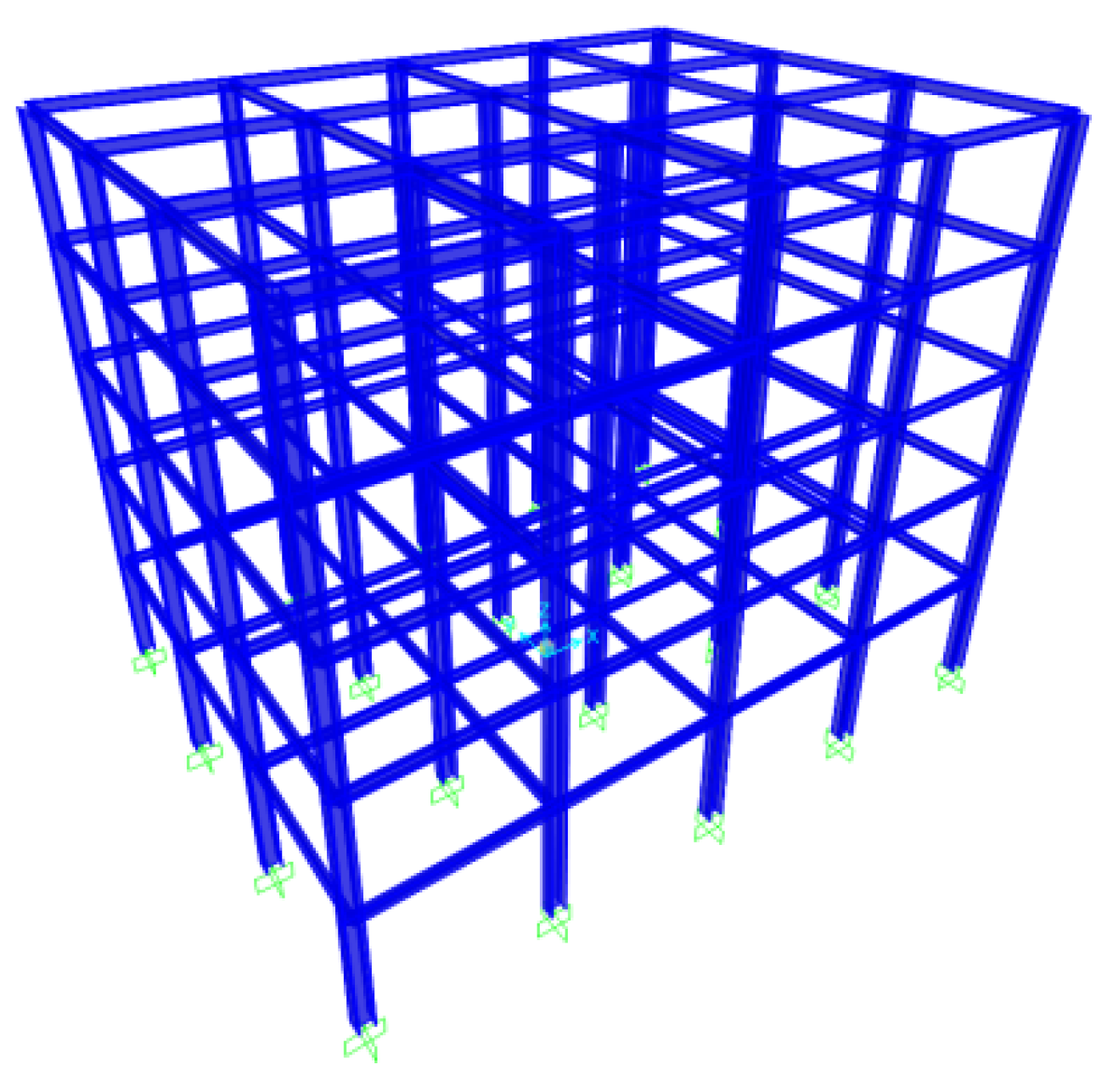
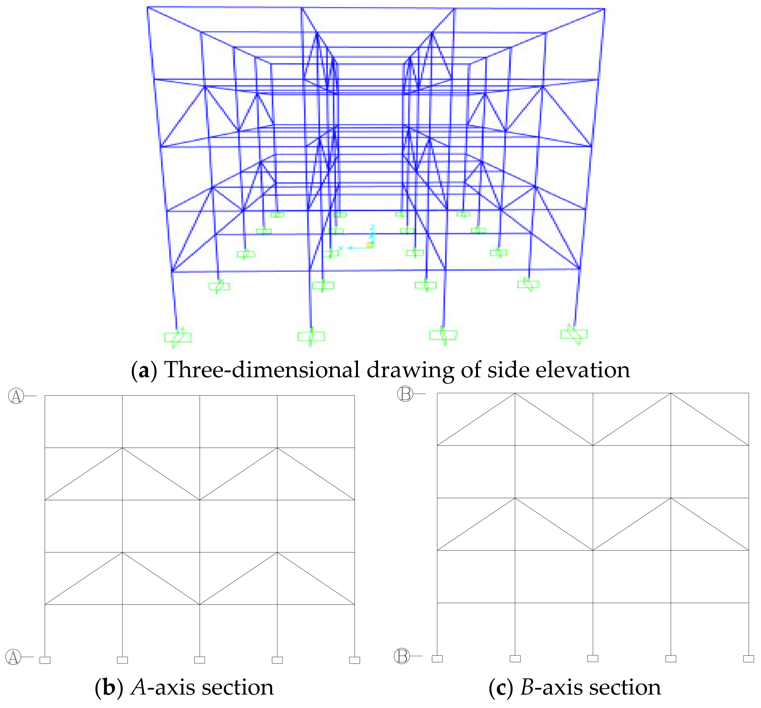
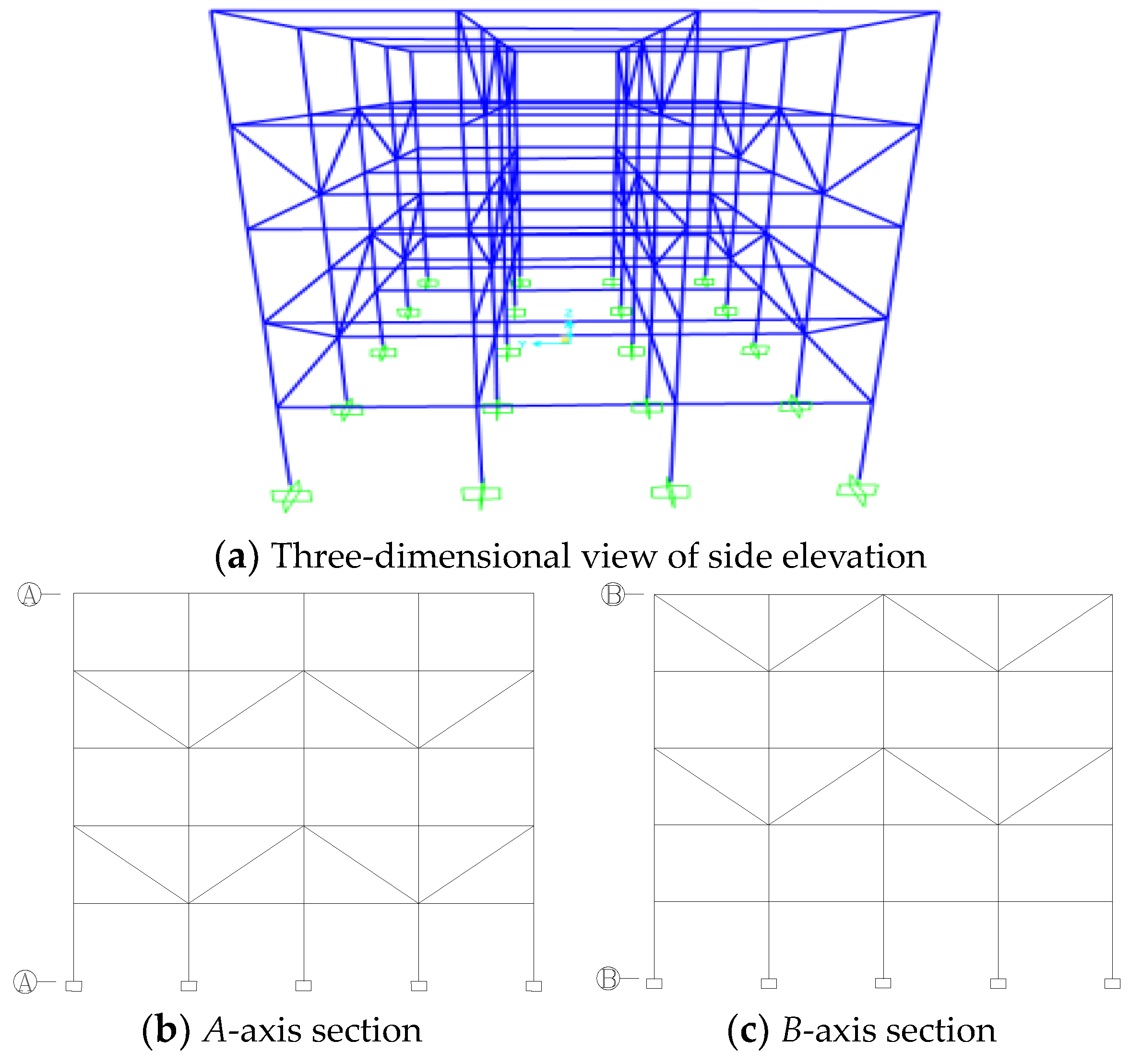
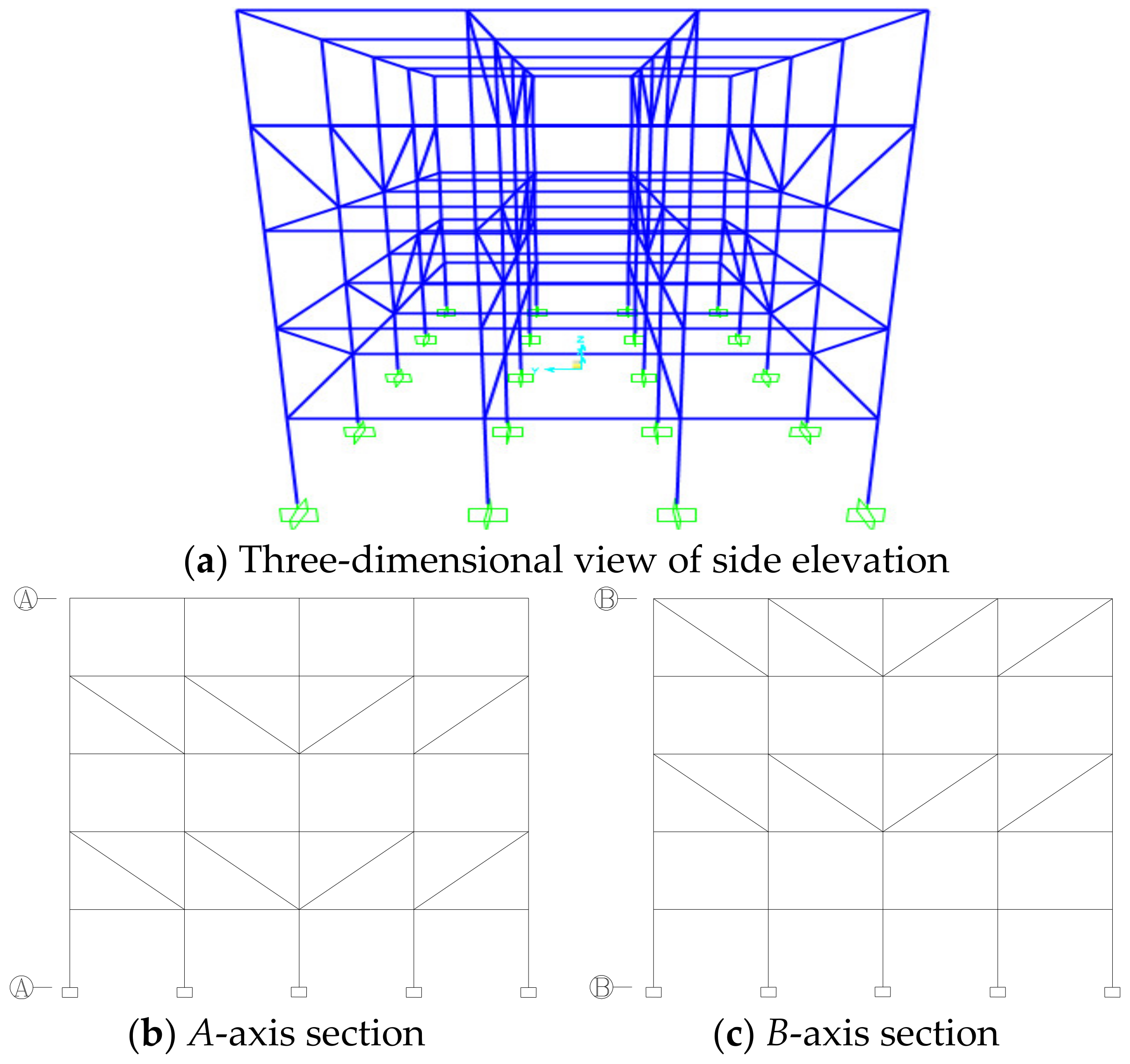
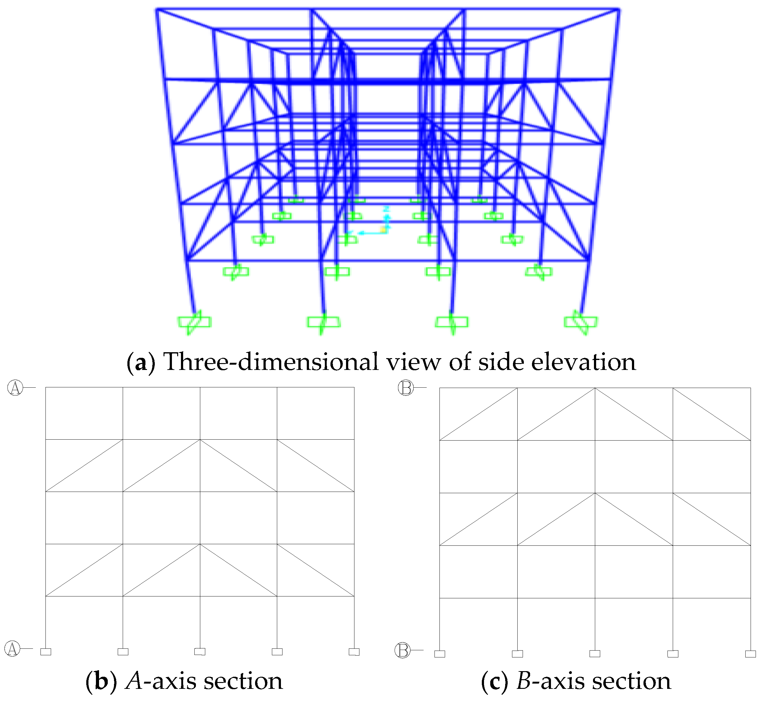
Figure 1 shows a plane view of Model A, and Figure 2 shows a three-dimensional view of Model A. Combining the interlocking truss system with the steel frame structure, the interlocking truss bracing was set up on the 2–5 floors of the steel frame structure, in which the A-axis and D-axis bracing forms were the same, and the B-axis and C-axis bracing forms were the same. The form of the brace was divided into Scheme 1 (Figure 3), Scheme 2 (Figure 4), Scheme 3 (Figure 5), and Scheme 4 (Figure 6).
2.2. Nonlinear Dynamic Analysis Methods
From GB 50010-2010 Code for the Design of Concrete Structures [23], designing structures against progressive collapse requires only the basic principles of design and conceptual design. In addition to the conceptual design method, there are three other essential methods for design analysis of critical members of a structure: local strengthening, pulling structural members, and removing members. The removal of members method, also known as the alternative path (AP) method, focuses on providing more efficient paths for the transmission of forces through the structure by removing one or more members of the structure, and if progressive collapse of the remaining structure occurs, by enhancing the load carrying capacity or ductility of the remaining structure. In general, the progressive collapse of structures is complex, and the results obtained by linear static forces are fast but conservative. The structure’s initial deformation is considered in the nonlinear dynamic analysis method. Then, the results obtained by the instantaneous loading method are more in line with the actual dynamic effects of the structure. Therefore, the alternative path (AP) method was used in this paper, and a nonlinear dynamic analysis of the structure was performed.
The sudden destruction of a column in a structure corresponds to the transfer of its load to the corresponding node in a very short period, and the node is subjected to a certain amount of dynamic impact. Thus, a structure’s progressive collapse is a nonlinear dynamic analysis process [24]. Before performing the dynamic analysis, firstly, a linear static analysis of the complete structural frame was carried out to obtain the internal forces (M, N, V) at the upper end of the proposed failed columns by applying loads to the frame structure according to the load combinations. Then, nonlinear dynamic analysis was performed. The process of analysis is given as follows: (1) The determined load combinations were applied to the original structure, and a linear static analysis was performed to obtain the internal forces of the columns before failure. (2) Then, the column was deleted, the value of the internal force before the failure of the column was reversed to the point of failure to make the structure statically equivalent to the original structure, and the initial state equivalent to the original structure was obtained by nonlinear static analysis. (3) The equilibrium duration was taken as = 0.1 s. This time frame was brief enough to capture the dynamic effects of column removal entirely. Then, the failure time of the member was taken as . The failure time cannot be greater than 0.1 times the vertical fundamental period of the remaining structure, which was taken as 0.01 s by default in this paper [25]. The integration time step was taken as 0.002 s. At = 0.1 s, the force acting back on the failure point was reduced to 0 for a certain period, simulating a sudden failure of the column.
The structure was dampened by Rayleigh damping. Since the structure’s vibration after the destruction of the bottom column was dominated by localized vertical vibration, modal analysis was carried out on the model with the bottom column deleted for each condition. Then, the vibration modes i and j, dominated by localized vertical vibrations, were identified, and the mass damping coefficient α and stiffness damping coefficient β were calculated [26].
where and are the intrinsic circular frequencies of structural vibration mode i and vibration mode j, respectively, of the deleted bottom column, and ξ is the damping ratio of the structure. According to the GB50017-2003 Code for Design of Steel Structures [27], the damping ratio of steel structures is 0.02.
2.3. Robustness Analysis Methods
Presently, the research on robustness is mainly categorized into structural performance and property aspects. There are two primary metrics for evaluating robustness: metrics based on structural performances and metrics based on structural properties [28]. In this paper, the effect of a staggered truss system on the robustness of steel frame structures was analyzed from the energy perspective by adopting the energy-based structural robustness index from the perspective of energy dissipation of structural members proposed by Fang et al. [29]. Thus, the resistance to progressive collapse of steel staggered truss systems can be analyzed more accurately.
Fang et al. believed that the destruction of structural materials requires the absorption or dissipation of energy, so it is reasonable and feasible to analyze the destruction of structures from an energy point of view. The advantage of evaluating robustness regarding the energy principle lies in its general applicability. It can provide conceptual guidance for structural robustness analysis of different materials and structural forms [29]. The advantage of examining structural failure from an energetic point of view also lies in its ability to respond to damage development. This approach can generalize changes in physical and mechanical properties such as deformation and strength-carrying capacities. The more energy the structure consumes after the failure of a member, the more loads the structure can withstand, the more robust the structure is, and the less likely it is to be destroyed.
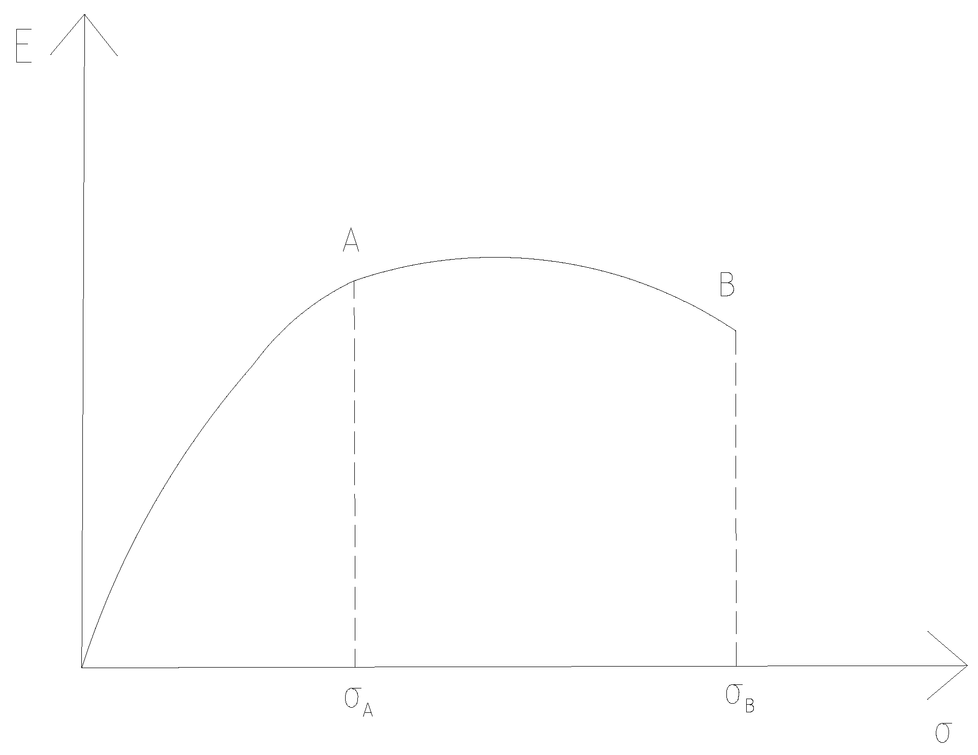
Take the static loading of a supported beam under concentrated load in the span as an example. Its load–deformation curve is shown in Figure 7. Points A and B correspond to the design load limit state and failure limit state points, and the projections on the horizontal axis are and , respectively.
In this paper, based on the calculation of structural robustness by energy proposed by Fang et al. [29], the formula for calculating the component robustness coefficient based on the energy dissipation capacity of the component is proposed.
In Equation (3), is the energy consumed by the beam in the structure to reach the yield state after the destruction of member i, and is the energy consumed by the beam in the structure to break after the destruction of member i. Define the structural robustness coefficient as the mean value of the component robustness coefficients.
In Equation (4), n is the number of members to be analyzed, and is the overall structural robustness factor. The smaller indicates that the weaker the energy dissipation capacity of the structure, the smaller the load that the structure can resist after the failure of member i, the more easily the structure will be damaged, and the less robust the structure will be.
2.4. Failure Criteria for Components
The criteria for determining whether a member is damaged or not in the structural analysis of this paper refer to the U.S. GSA design guidelines. The load combinations are determined according to the GSA design guidelines [30], where DL is the dead load, and LL is the live load.
1.2DL + 0.5LL
The criteria for determining whether a member in the nonlinear analysis is damaged were determined based on the GSA design guidelines: determining whether the ductility ratios and plastic hinge rotation are damaged. In this paper, the plastic hinge rotation and ductility ratio limits for the members of the steel structural system are set as shown in Table 1. In this case, the significance of the ductility ratio is the ratio of the maximum deflection at the reference point (e.g., at the failed column) to the yield deflection, and the significance of the plastic hinge rotation of repose is the ratio of the maximum deflection to the length of the beam.
3. Results
3.1. Removal of Single Column at Ground Floor Level
3.1.1. Displacement of the Tops of Failed Columns
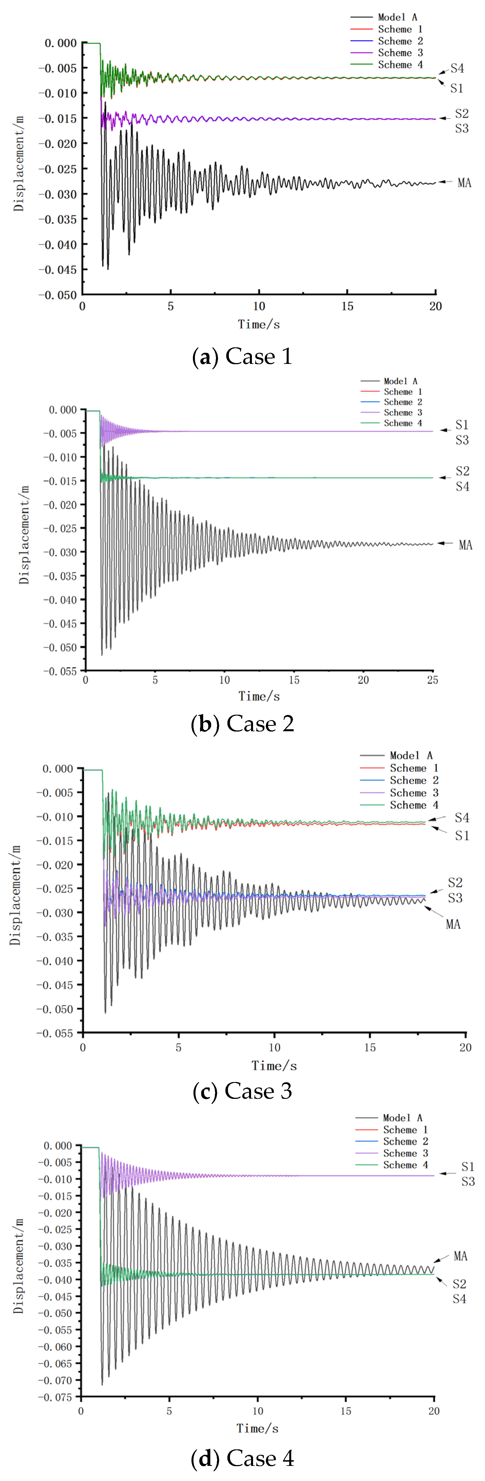
The strength of the dynamic response of the structure during progressive collapse can be analyzed by the variation in the vertical displacement at the point of failure with time and the variation in the axial force in each column of the structure under the progressive collapse condition [31]. Figure 8 shows the displacement–time history curves at the top of the failed column for five models under working conditions 1–4. The vertical axis of the coordinate axis is the vertical displacement of the failure point, which is positive upward, and the horizontal axis of the coordinate axis is the analysis time.
Table 2 shows the peak vertical displacements and yield displacements at the failure point after the failure of the columns in Cases 1–4. In all cases, Case 1 is the failure of corner column A1, Case 2 is the failure of long-side center column A3, Case 3 is the failure of short-side center column B1, and Case 4 is the failure of inner column B3.
In Case 1, after the failure of the corner columns, the peak displacements and yield displacements of the steel frame structure with four arrangements of staggered trusses were significantly reduced compared with the un-braced steel frame structure (Model A). The maximum displacements at the failure point were reduced by 75.13%, 61.29%, 61.11%, and 75.57%, respectively, for the structure of Model A combined with the staggered truss system compared to the original structure. This is because when the corner columns failed, the diagonal braces arranged on the upper level of the failed columns formed a truss with the columns and beams, thus reducing the displacements of the failed columns’ tops by improving the vertical stiffness of the structure. In each case, Scheme 1 and Scheme 4 reduced the peak vertical displacements at the failure point to a greater extent. Scheme 2 and Scheme 3 were more effective in reducing the vibration amplitudes of the nodes after column failure. The plastic hinge angles of the five structures at the failure point in Case 1 were 0.0075, 0.0019, 0.0029, 0.0029, and 0.0018, respectively.
Case 2 and Case 3 were center column failures, and all four schemes effectively reduced the peak vertical displacements and yield displacements at the failure point. In Case 2, the displacements at the failure point were reduced by 84.05%, 70.37%, 84.14%, and 70.35%, respectively, in the structure of Model A combined with the staggered truss system compared to the original structure. In Case 3, the displacements at the failure point were reduced by 63.01%, 36.28%, 35.57%, and 63.14%, respectively. However, in Case 2, Schemes 1 and 3 significantly reduced the vertical displacements at the failure point, and Schemes 2 and 4 were more effective in reducing the vibration amplitudes of the node after the extraction of the failed column. In Case 3, Schemes 1 and 4 significantly reduced the vertical displacements at the failure point, and Schemes 2 and 3 were more effective in reducing the vibration amplitudes of the node after the extraction of the failed column. The four staggered truss systems in Case 2 were more effective in reducing the peak vertical displacements and yield displacements at the failure point. The plastic hinge angles of the five structures at the failure point in Case 2 were 0.0086, 0.0014, 0.0025, 0.0013, and 0.0025 and 0.0084, 0.0031, 0.0054, 0.0054, and 0.0031 in Case 3, respectively.
Case 4 is an internal column failure, and the peak displacements of the four schemes were significantly reduced compared to Model A. The displacements at the failure point were reduced by 76.81%, 41.10%, 76.87%, and 41.13%, respectively. However, the yield displacements at the failure point in Schemes 2 and 4 increased compared to Model A. The plastic hinge angles of the five structures at the point of failure in Case 4 were 0.0119, 0.0027, 0.0070, 0.0027, and 0.0070, respectively.
The peak vertical displacements and yield displacement values at the failure point in all four schemes were significantly reduced in the case of single-column failure. However, the magnitudes of the reduction were different for each scheme and each case. This is because in Case 1 and Case 2, the failed columns were located in the supported span, while in Case 3 and Case 4, the failed columns were not supported in the upper span. The plastic hinge angle at the point of failure did not exceed the GSA design criteria for any of the four conditions, and the structure did not collapse. Here, YD stands for the yield displacement, while PD stands for the peak displacement.
3.1.2. Axial Forces in Adjacent Columns of Failed Columns
Table 3 shows the axial force values of the bottom neighboring columns of the failed columns in Cases 1–4 before and after damage.
In Case 1, the peak axial forces of columns A2 and B1 in Model A increased by 305 kN and 292 kN, respectively, compared with those before column removal, which indicates that most of the axial forces initially borne by the failed columns were transferred to column B1 through Vierendeel action. In all four schemes, the increase in peak axial force was more significant in column A2 than in column B1. A truss structure usually consists of beams and columns, and nodes connect these members to form a stable structure. In all four schemes, the lateral supports above the failure columns and the trusses formed by the beams and columns supported and transferred the loads to the A2 columns, which were in the same plane as the supports.
In Case 2, the peak increase in axial force in column A2 was more significant than that in column B3 because, in all four schemes, the trusses above the failed columns transferred most of the loads that would otherwise be carried by the failed columns A3 to the A2 columns in the same plane through the truss structure above.
Case 3 was similar to Case 2 in that most of the load initially carried by the failed column B1 was transferred to column B2.
In Case 4, the peak axial force in columns A3 and C3 of the four schemes decreased compared to the increase in Model A. Column B2 showed an increase in the peak axial force after the failure of column B3. This is because the loads initially carried by the failed columns were transferred to column B2, which was in the same plane as the truss, through the truss above the failed columns.
3.2. Removal of Upper Single Column Conditions
3.2.1. Displacement of the Tops of Failed Columns
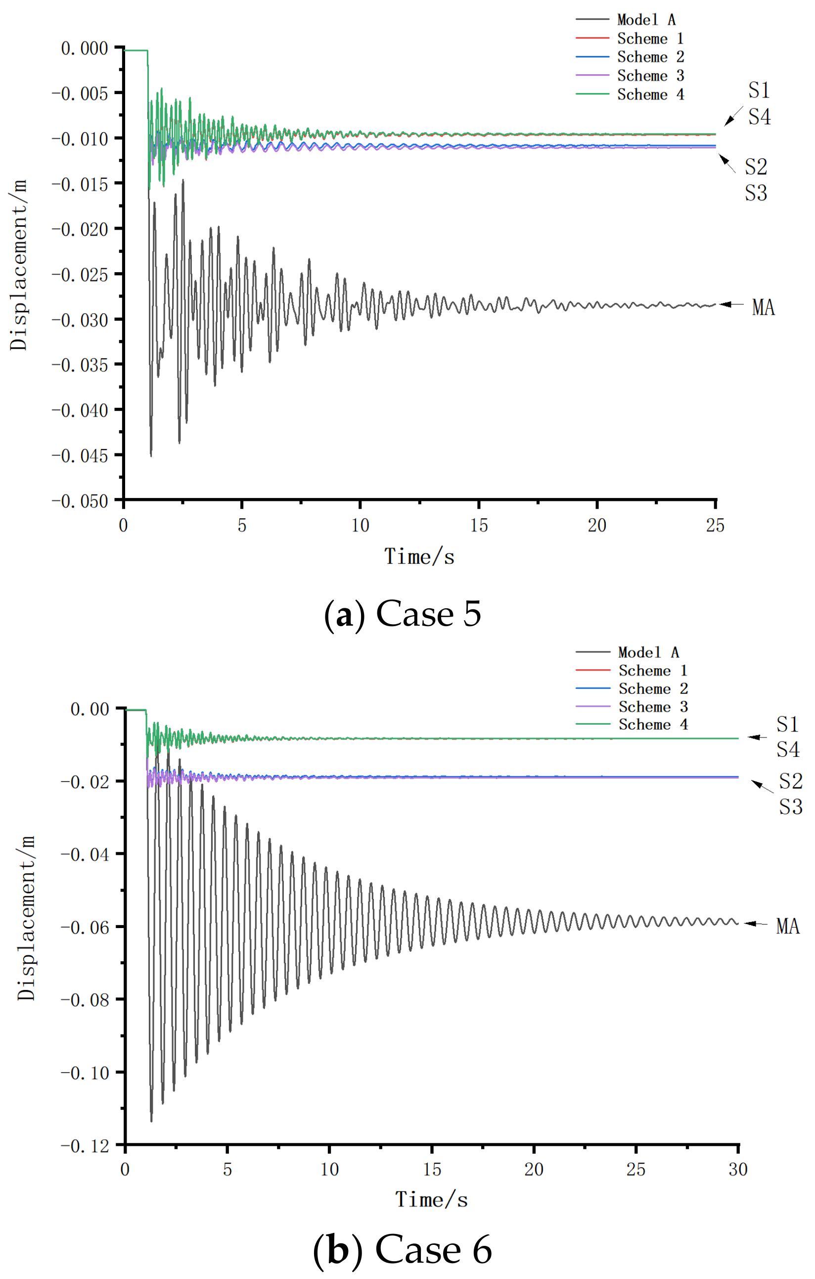
Figure 9 shows the displacement–time history curves at the top of the failed column for the five models under Case 5 and Case 6. In both cases, Case 5 was the failure of a two-story A1 column, and Case 6 was the failure of a three-story A1 column.
Table 4 shows the vertical yield and peak displacements at the top of the failed column after column failure in Case 1, Case 5, and Case 6. Case 1 was a one-story corner column failure, Case 5 was a two-story corner column failure, and Case 6 was a three-story corner column failure.
All four schemes of arranging the braces in the three working conditions could effectively reduce the vertical yield and peak displacements at the top of the failed column and reduce the vibration amplitudes at the failure point. In Case 1 and Case 6, the two frame structures, Scheme 1 and Scheme 4, were more effective in reducing the vertical displacements at the failure point. In Case 5, Schemes 2 and 3 were more effective in reducing the vertical displacements at the failure point but were not significantly different from Schemes 1 and 4. This is because staggered truss braces were arranged on the upper floors of the corner columns on both the first and third floors. After the columns failed, the transverse braces formed a truss with the beams and columns, which could effectively resist the vertical loads, thus reducing the vertical displacements at the failure point. By comparing the vertical displacements at the failure point after removing the corner columns of different layers, it can be known that arranging anti-slope braces above the failure point was more effective than arranging positive-slope braces in reducing the vertical displacements at the failure point. The plastic hinge angles at the failure point for the five structures in Case 5 were 0.0075, 0.0026, 0.0036, 0.0036, and 0.0023 and 0.0189, 0.0023, 0.0036, 0.0036, 0.0023, and 0.0023 for Case 6, respectively, and did not exceed the GSA design criteria for the two cases. GSA design criteria and the structure did not collapse. Here, YD stands for the yield displacement, while PD stands for the peak displacement.
3.2.2. Axial Forces in Adjacent Columns of Failed Columns
Table 5 shows the axial force values of the bottom adjacent columns of the failed columns in Case 5 and Case 6 before and after damage.
In Case 5, the peak axial forces of columns B1 and A2 in Model A increased by 226 kN and 236 kN, respectively, compared with those before column removal, which indicates that most of the axial forces initially borne by the failed columns were transferred to column A2. In all four schemes, the peak increase in axial force in column A2 was more significant than in column B1. The truss was formed by the transverse brace above the failed columns, and the beams and columns acted as a brace and transferred the load to column A1, which was in the same plane as the brace. Case 6 was similar to Case 5.
By comparing the conditions of removing the one-story corner column, two-story corner column, and three-story corner column, it can be concluded that when bracing was arranged on the upper stories of the failed column, the bracing could effectively reduce the peak vertical displacements and yield displacements at the failure point. However, the axial force of the failed column would be transferred to the columns in the same plane as the truss through the truss formed by the transverse braces, beams, and columns above the failed column. Therefore, when designing a structure with braced members, it is necessary to increase the load-carrying capacity of the critical member and simultaneously increase the load-carrying capacity of the column member in the same plane as the truss above it.
3.3. Removal of Multiple Columns
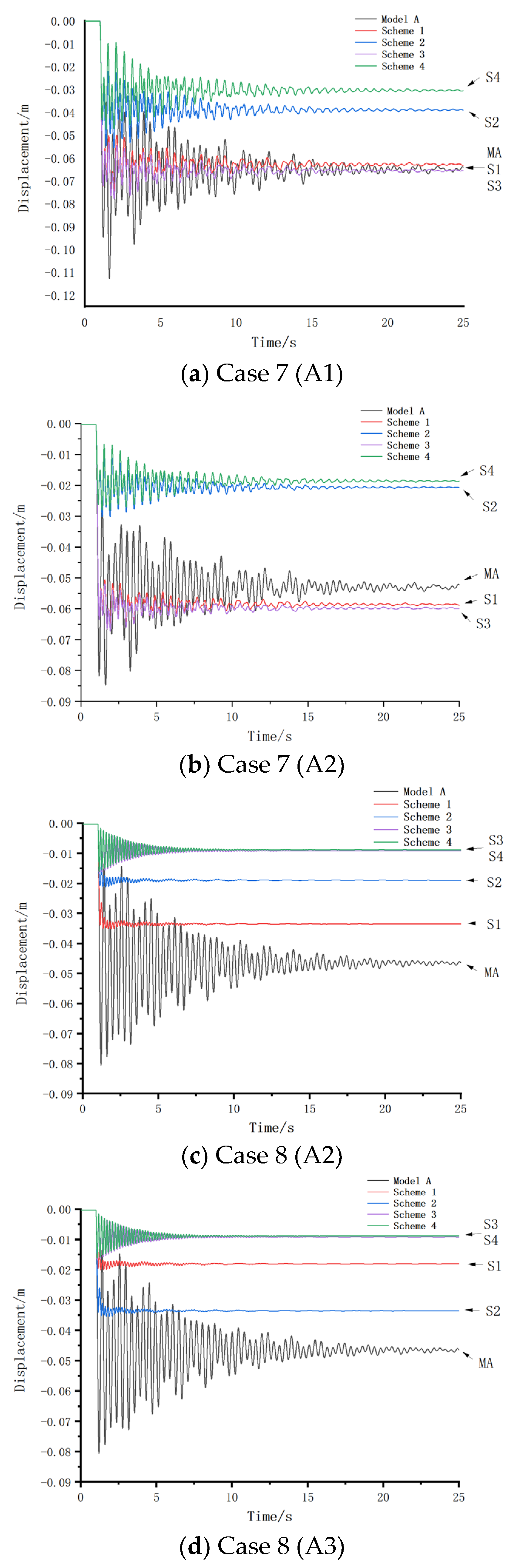
Figure 10 shows the displacement–time history curves at the top of the failed column for the five models in Case 7 and Case 8. Table 6 gives the vertical yield displacement and peak displacement values at the top of the failed column after column failure in Cases 7 and 8. Here, YD stands for the yield displacement, while PD stands for the peak displacement.
Case 7 was the failure of a corner column and the adjacent long-side edge column. Schemes 2 and 4 effectively reduced the vertical displacements at the top of the failed column, and the amplitudes of the vibration at the failure point were also significantly reduced after the failure of both columns in Schemes 2 and 4. Schemes 1 and 3 only reduced the peak vertical displacements and vibration amplitudes at the failure point after column failure.
Case 8 was the failure of two adjacent side columns on the long side. According to the graph, all four schemes reduce the peak vertical and yield displacements at the failure point. In each case, Schemes 3 and 4 are more effective in reducing the vertical displacements at the failure point. This indicates that the bracing of the structure’s second floor in Schemes 3 and 4 can effectively improve the vertical stiffness of the structure, which is more effective in reducing the vertical displacements at the failure point when the center column on the long side fails.
3.4. Discussion
From the analysis of the above data, it can be seen that all four schemes could effectively reduce the maximum displacements and yield displacements at the failure point after column failure, so there was a significant improvement in the structure’s resistance to progressive collapse. It shows that the staggered truss system could effectively reduce the deformations of steel structures after column failure. The progressive collapse resistance of the steel frame structure was improved. This effect was due to the fact that the horizontal braces were arranged above the failure columns. This staggered arrangement of braces was equivalent to arranging horizontal reinforcement layers at every other level in the entire frame structure, which could form a planar frame with the beams and columns, thus significantly reducing the vertical displacement of the structure at the localized damage [20]. When the structural corner columns failed, Schemes 1 and 4 had similar degrees of impact on the structure’s ability to resist progressive collapse, and Schemes 2 and 3 had similar degrees of impact on the structure’s performance in resisting progressive collapse. This was due to the fact that Schemes 1 and 4 had the same form of bracing for the side-span arrangement, which was orthotropic. In contrast, Schemes 2 and 3 had the same form of bracing for the side-span arrangement, which was anti-tropic bracing, which led to similar displacements at the point of failure for the two groups of structures after the columns failed. When the structure sustained a long-side center column failure, the degrees of impact on the structure’s ability to resist progressive collapse were similar for Schemes 1 and 3. The degrees of impact on the structure’s ability to resist progressive collapse were similar for Schemes 2 and 4 because the forms of bracing arranged in the two adjacent spans above the failed columns were the same in Schemes 1 and 3. The forms of bracing were the same in the two adjacent spans in Schemes 2 and 4. In the case of failure of the inner column, the situations of the four structural models were similar to that of removing the long-side center column. This related to bracing in the two adjacent spans above the failed column.
4. Robustness Analysis Results
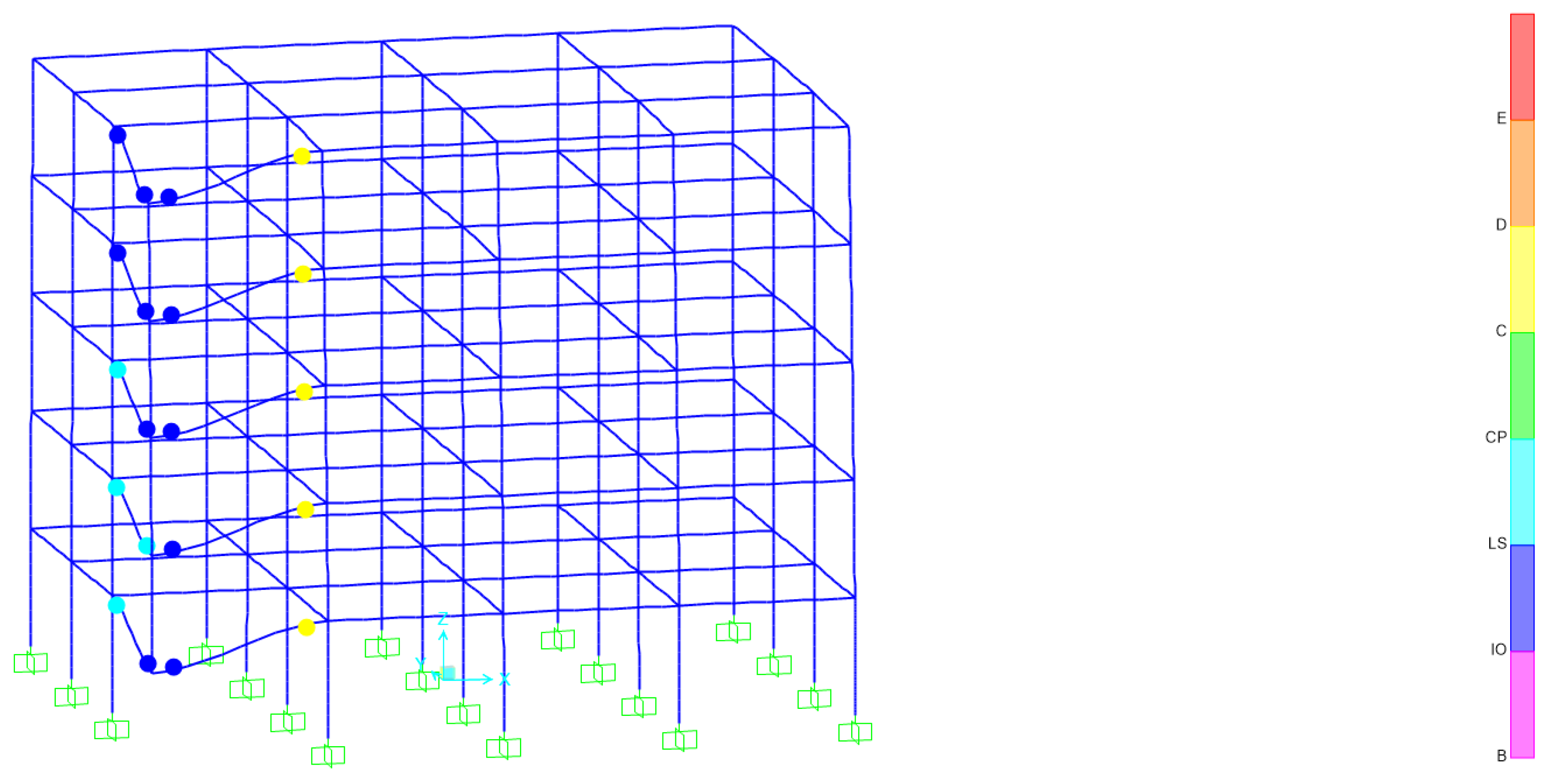
In SAP2000, hinges could be used to simulate their force behavior for beams in structures. When analyzed using Pushover, the plastic hinge state on the beam was at B to ≤C and yielding of the beam would occur; at C to ≤D, damage of the member would occur. Taking the removal of the bottom corner column as an example, after removing the member, the structure would develop a plastic hinge, as shown in Figure 11.
The structural robustness coefficient calculation method proposed in this paper mainly focused on the vertical progressive collapse resistance of frame structures. The frame columns mainly bore the vertical loads of the structure because the bottom frame columns bore the largest loads and were more likely to be damaged by accidental events in practice. Hence, the structural robustness coefficients in this paper were only calculated for the bottom column members of the frame.
The following is an example of the calculation process of the robustness coefficient of a three-bay steel frame structure given in Model A. When column A1 failed, the energy consumed by the beams in the structure to reach the yield state would be 104.77 MPa; when the beams were damaged, the structure would consume energy of 714.94 MPa; and the value was brought into Equation (4) to figure out that would be 1.172. The same method was used to calculate the member robustness factor for removing the remaining bottom columns, as follows: was 1.129 and was 1.130; the structural robustness coefficient for Model A was calculated as 1.144 by bringing the component robustness coefficients into Equation (5).
Referring to the above calculation process, the robustness coefficients of the remaining four three-bay steel frame structures are calculated by combining Equations (4) and (5), and the results are shown in Table 7.
Analysis of the calculation results shows that the staggered truss system can effectively improve the robustness of the members in the steel frame structure, thus improving the overall robustness of the structure. Reasonable utilization of the brace system can improve the redundancy of the structure, thus enhancing the structure’s performance against vertical progressive collapse. In summary, the robustness index can effectively guide the design of steel structures against vertical collapse and adjust the structural safety for structural optimization.
5. Conclusions
In this paper, the nonlinear dynamic analysis of the steel structure braced with four kinds of staggered trusses and the unsupported steel structure is carried out by removing members. The performances of the three conditions of removing the corner, long-side center, and inner columns in resisting the progressive collapse are analyzed. The time history curves of displacement of the failure points and the axial force values of the adjacent columns under the five conditions are comparatively analyzed. Then, the method of calculating the coefficients of the robustness of the structure based on the energy is proposed to research the effect of the staggered truss system on the robustness of steel structures. The conclusions can be drawn as follows.
- (1)
- The staggered truss system can effectively reduce the vertical displacements and vibration amplitudes at the failure point after column failure, and the peak displacements at the failure point can be reduced by 84% at most and 41% at least compared with the pure frame structure.
- (2)
- The staggered truss system reduces the peak axial force in some of the columns adjacent to the failed column.
- (3)
- The staggered truss system is more effective in enhancing the structural resistance to progressive collapse in case of failure of corner columns and long-side center columns of steel frame structures.
- (4)
- Designing a structure with braced members can increase the critical members’ load-carrying capacities while increasing the column members’ load-carrying capacities in the same plane as the trusses above them.
- (5)
- The structural robustness coefficients of Model A, Scheme 1 braced frame, Scheme 2 braced frame, Scheme 3 braced frame, and Scheme 4 braced frame are 1.144, 1.339, 1.306, 1.584, and 1.176, respectively, indicating that enhancing the redundancy of the structure can effectively improve the structural robustness, and a reasonable bracing arrangement can make the structure have better redundancy and thus better resistance to progressive collapse. The structure has better resistance to progressive collapse.
- (6)
- The amounts of steel used in the four models are equal, only the form of bracing is varied, and overall, Scheme 1 is better optimized for the structure’s performance against progressive collapse than the other three schemes.
- (7)
- The appearance of the staggered truss system is beautiful and changeable, and the progressive collapse resistance of the structure is also significantly improved. However, due to the limitation of the site, it is not possible to experimentally study the progressive collapse resistance of steel frame staggered truss systems, and it is hoped that some researchers can experimentally study the progressive collapse resistance of staggered truss systems in the future. This study does not consider the effect of floor slabs on the progressive collapse resistance of this structure. It is hoped that some researchers will consider studying the effect of floor slabs on the progressive collapse resistance of this frame structure in the future.
Author Contributions
Writing—original draft preparation, Y.F.; supervision, C.K. and J.J. All authors have read and agreed to the published version of the manuscript.
Funding
This research received no external funding.
Data Availability Statement
The data presented in the study are included in the article, further inquiries can be directed to the authors.
Conflicts of Interest
The authors declare no conflict of interest.
References
- Kiakojouri, F.; De Biagi, V.; Chiaia, B.; Sheidaii, M.R. Strengthening and retrofitting techniques to mitigate progressive collapse: A critical review and future research agenda. Eng. Struct. 2022, 262, 114274. [Google Scholar] [CrossRef]
- Ke, C.; Liu, Q. Application of sensitivity analysis to progressive collapse resistance of planar truss structures. Appl. Sci. 2022, 12, 6273. [Google Scholar] [CrossRef]
- Zhao, R.; Chen, G.; Zhang, Z.; Luo, W. Progressive collapse resistance assessment of a multi-column frame tube structure with an assembled truss beam composite floor under different column removal conditions. Buildings 2023, 14, 111. [Google Scholar] [CrossRef]
- Anas, S.M.; Alam, M.; Umair, M. Experimental and numerical investigations on performance of reinforced concrete slabs under explosive-induced air-blast loading: A state-of-the-art review. Structures 2021, 31, 428–461. [Google Scholar] [CrossRef]
- Masoomzadeh, M.; Basim, M.C.; Chenaghlou, M.R.; Khajehsaeid, H. Probabilistic performance assessment of eccentric braced frames using artificial neural networks combined with correlation latin hypercube sampling. Structures 2023, 240, 48226. [Google Scholar] [CrossRef]
- Hammad, A.; Moustafa, A.M. Shake table tests of special concentric braced frames under short and long duration earthquakes. Eng. Struct. 2019, 200, 109695. [Google Scholar] [CrossRef]
- Hansen, R.J.; Messurier, W.J.; Paul, P.J. New steel framing system promises major savings in high-rise apartments. Archit. Rec. 1966, 139, 191–196. [Google Scholar]
- Bakke, H.P.; Kloiber, L.A.; Nuhn, A.C. Staggered truss building system. Civ. Eng. ASCE 1969, 39, 56–59. [Google Scholar]
- Goel, S.C.; Itani, A.M. Seismic behavior of open-web truss-moment frames. J. Struct. Eng. 1994, 120, 1763–1780. [Google Scholar] [CrossRef]
- Wahyuni, E.; Tethool, Y. Effect of Vierendeel panel width and vertical truss spacing ratio in staggered truss framing system under earthquake loads. Int. J. Civ. Eng. 2014, 13, 213–221. [Google Scholar]
- Kim, J.; Lee, J. Seismic retrofit schemes for staggered truss structures. Eng. Struct. 2015, 102, 93–107. [Google Scholar] [CrossRef]
- Xu, H.; Zhou, X. Analysis of Global Ductility of Staggered Truss Steel Frame in Severe Earthquake; Hunan University: Changsha, China, 2003. [Google Scholar]
- Zhou, X.; Huang, W.; Zhou, Q.; Zhou, Z.; Guo, W. Pseudo-dynamic test and numerical analyses of staggered truss framing systems. Structures 2022, 522, 45509. [Google Scholar] [CrossRef]
- Zhou, X.; Zhou, Z.; Zhou, Q.; Huang, W.; Guo, W. Hysteretic behavior and design considerations of staggered truss framing systems. J. Build. Eng. 2023, 72, 106696. [Google Scholar] [CrossRef]
- Zhou, X.; Zhou, Q.; Huang, X. Calculation of internal forces of staggered truss structures subjected to vertical loads. Eng. Mech. 2004, 21, 25–30. [Google Scholar]
- Zong, Z. Plastic Design of Special Staggered Truss Based on Energy Balance; Xi’an University of Architecture and Technology: Xi’an, China, 2014. [Google Scholar]
- Soo, Y.H.; Jong, E.Y.; Soon, C.R. Seismic performance evaluation of staggered truss system by the shape of truss. J. Comput. Struct. Eng. Inst. Korea 2017, 30, 397–404. [Google Scholar]
- Liu, Q.; Liao, T.; Peng, X.; Xu, S. Analysis of seismic performance of assembled steel structure staggered truss system. In IOP Conference Series: Earth and Environmental Science; IOP Publishing: Bristol, UK, 2021; Volume 783. [Google Scholar]
- Chen, Y.; Ke, K.; Yi, J.; Liu, Z.; Ye, D.; Xu, G.; Yuan, S. Seismic performance of steel staggered truss frame equipped with brace-type hybrid dampers with multiple nonlinear stages. Case Stud. Constr. Mater. 2023, 18, e02158. [Google Scholar] [CrossRef]
- Liang, P. Progressive Collapse Analysis and Robustness Research of Prestressed Fabricated Concrete Frame; Hunan University: Changsha, China, 2018. [Google Scholar]
- Zang, X.; Lv, C.; Dong, L.; Zhou, N. Effect of bracing on the resistance of progressive collapse of prefabricated steel frame structures. Steel Struct. 2018, 33, 1620+82. [Google Scholar]
- UFC 4-023-03; Design of Buildings to Resist Progressive Collapse. Department of Defense: Washington, DC, USA, 2013.
- GB50010-2010; Code for Design of Concrete Structure. China Architecture and Building Press: Beijing, China, 2010.
- Diao, Y.; Sun, Y.; Cao, Y. Effect of eccentric braces on progressive collapse resistance of high-rise steel frame structures. Steel Struct. 2016, 31, 53–59. [Google Scholar]
- Nanci, B.; Shalva, M. SDOF Model for Progressive Collapse Analysis. In Proceedings of the Structures Congress and Exposition, New York, NY, USA, 20–24 April 2005. [Google Scholar]
- Clough, R.; Penzzien, J. Dynamics of Structures, 2nd ed.; McGraw-Hill: New York, NY, USA, 1993. [Google Scholar]
- GB 50017-2003; Code for Design of Steel Structures. Architecture & Building Press: Beijing, China, 2003.
- Gong, Y.; Yan, Y.; Li, Z. Analyze of eccentrically web members influence on the seismic performance of staggered-truss system. J. Liaoning Univ. Eng. Technol. (Nat. Sci. Ed.) 2016, 35, 1122–1125. (In Chinese) [Google Scholar]
- Fang, Z.; Li, H. Structural robustness, and risk mitigation. Eng. Mech. 2007, 24, 79–82. [Google Scholar]
- GSA. Alternate Path Analysis and Design Guidelines for Progressive Collapse Resistance; U.S. General Service Administration: Washington, DC, USA, 2016.
- Ge, S.; Lai, W. Analysis of steel staggered Vierendeel truss frame based on the progressive collapse. Steel Struct. 2015, 30, 19–23. [Google Scholar]
Figure 1.
Plane view of Model A.

Figure 2.
Three-dimensional view of Model A.

Figure 3.
Scheme 1—side elevation 3D view and sections.

Figure 4.
Scheme 2—side elevation 3D view and section.

Figure 5.
Scheme 3—side elevation 3D view and section.

Figure 6.
Scheme 4—side elevation 3D view and section.

Figure 7.
Load–deformation curve of a simple beam.

Figure 8.
Vertical displacements of column top after the failure of bottom single column.

Figure 9.
Vertical displacements of column top after the failure of upper single column.

Figure 10.
Vertical displacements of column tops after the failure of multiple columns.

Figure 11.
Schematic diagram of beam hinge after removal of ground floor corner columns.


Table 1.
Limits of plastic hinge rotations and ductility ratios of structural steel members.
| Structural Member | Ductility Ratio | Plastic Hinge Rotation |
|---|---|---|
| Beams | 20 | 0.21 |
| Column (tensile control) | 20 | 0.21 |
| Column (pressure control) | 1 | - |
Table 2.
Yield displacements and peak displacements at the tops of the failed columns (mm).
| Case | Failure Column | Model A | Scheme 1 | Scheme 2 | Scheme 3 | Scheme 4 | |||||
|---|---|---|---|---|---|---|---|---|---|---|---|
| YD | PD | YD | PD | YD | PD | YD | PD | YD | PD | ||
| 1 | A1 | 19.52 | 45.03 | 7.00 | 11.20 | 15.11 | 17.43 | 15.08 | 17.51 | 7.01 | 11.00 |
| 2 | A3 | 24.35 | 51.78 | 4.62 | 8.26 | 14.41 | 15.34 | 4.61 | 8.21 | 14.40 | 15.35 |
| 3 | B1 | 17.85 | 50.99 | 11.62 | 18.86 | 26.41 | 32.85 | 26.40 | 32.85 | 11.59 | 18.79 |
| 4 | B3 | 37.10 | 71.51 | 9.11 | 16.58 | 38.41 | 42.12 | 9.12 | 16.54 | 38.40 | 42.10 |
Table 3.
Axial forces in adjacent columns of failed columns (kN).
| Case | Failure Column | Neighboring Column | Model A | Scheme 1 | Scheme 2 | |||
| Before Column Removal | After Column Removal | Before Column Removal | After Column Removal | Before Column Removal | After Column Removal | |||
| 1 | A1 | A2 | 522.32 | 827.70 | 497.33 | 1098.35 | 530.79 | 975.68 |
| B1 | 516.76 | 808.35 | 550.37 | 619.64 | 530.54 | 634.02 | ||
| 2 | A3 | A2 (A4) | 522.32 | 892.95 | 497.33 | 1018.99 | 530.79 | 988.74 |
| B3 | 972.71 | 1308.15 | 1000.80 | 1069.93 | 957.84 | 1040.56 | ||
| 3 | B1 | C1 | 516.76 | 870.54 | 550.37 | 686.50 | 530.54 | 742.95 |
| B2 | 971.98 | 1319.49 | 929.66 | 1893.41 | 891.74 | 1650.53 | ||
| A1 | 288.25 | 619.13 | 497.33 | 512.95 | 296.71 | 494.58 | ||
| 4 | B3 | B2 (B4) | 971.98 | 1454.90 | 896.72 | 1862.90 | 926.49 | 1548.41 |
| C3 | 972.71 | 1454.11 | 1004.64 | 1116.02 | 957.84 | 1202.00 | ||
| A3 | 522.73 | 978.20 | 549.06 | 639.98 | 509.72 | 738.79 | ||
| Case | Failure Column | Neighboring Column | Model A | Scheme 3 | Scheme 4 | |||
| Before Column Removal | After Column Removal | Before Column Removal | After Column Removal | Before Column Removal | After Column Removal | |||
| 1 | A1 | A2 | 522.32 | 827.70 | 510.70 | 965.35 | 517.46 | 1119.04 |
| B1 | 516.76 | 808.35 | 531.83 | 636.94 | 549.54 | 618.05 | ||
| 2 | A3 | A2 (A4) | 522.32 | 892.95 | 500.75 | 1051.14 | 517.46 | 876.71 |
| B3 | 972.71 | 1308.15 | 1000.10 | 1069.10 | 958.39 | 1041.11 | ||
| 3 | B1 | C1 | 516.76 | 870.54 | 531.83 | 748.02 | 549.54 | 683.21 |
| B2 | 971.98 | 1319.49 | 848.86 | 1609.75 | 956.73 | 1914.39 | ||
| A1 | 288.25 | 619.13 | 510.70 | 533.98 | 309.71 | 425.14 | ||
| 4 | B3 | B2 (B4) | 971.98 | 1454.90 | 876.73 | 1923.03 | 856.77 | 1886.97 |
| C3 | 972.71 | 1454.11 | 1004.53 | 1115.22 | 951.36 | 1052.71 | ||
| A3 | 522.73 | 978.20 | 547.75 | 638.68 | 592.38 | 510.34 | ||
Table 4.
Yield displacements and peak displacements at the tops of the failed columns (mm).
| Case | Failure Column | Model A | Scheme 1 | Scheme 2 | Scheme 3 | Scheme 4 | |||||
|---|---|---|---|---|---|---|---|---|---|---|---|
| YD | PD | YD | PD | YD | PD | YD | PD | YD | PD | ||
| 1 | 1-A1 | 19.52 | 45.03 | 7.00 | 11.20 | 15.11 | 17.43 | 15.08 | 17.51 | 7.01 | 11.00 |
| 5 | 2-A1 | 28.44 | 45.19 | 9.57 | 15.58 | 11.07 | 12.68 | 11.09 | 12.95 | 9.55 | 15.63 |
| 6 | 3-A1 | 59.23 | 113.35 | 8.26 | 13.68 | 19.08 | 21.52 | 19.09 | 21.79 | 8.25 | 13.61 |
Table 5.
Axial forces in adjacent columns of failed columns in kN.
| Case | Failure Column | Neighboring Column | Model A | Scheme 1 | Scheme 2 | |||
| Before Column Removal | After Column Removal | Before Column Removal | After Column Removal | Before Column Removal | After Column Removal | |||
| 5 | 2-A1 | B1 | 413.27 | 639.82 | 447.14 | 521.84 | 427.59 | 486.37 |
| A2 | 416.33 | 652.65 | 390.82 | 813.27 | 415.71 | 677.76 | ||
| 6 | 3-A1 | B1 | 310.61 | 482.86 | 322.53 | 370.53 | 323.27 | 397.71 |
| A2 | 313.88 | 495.92 | 302.86 | 663.67 | 311.84 | 608.98 | ||
| Case | Failure Column | Neighboring Column | Model A | Scheme 3 | Scheme 4 | |||
| Before Column Removal | After Column Removal | Before Column Removal | After Column Removal | Before Column Removal | After Column Removal | |||
| 5 | 2-A1 | B1 | 413.27 | 639.82 | 428.41 | 488.16 | 445.92 | 521.02 |
| A2 | 416.33 | 652.65 | 404.08 | 722.45 | 404.08 | 618.05 | ||
| 6 | 3-A1 | B1 | 310.61 | 482.86 | 324.90 | 398.04 | 322.53 | 370.04 |
| A2 | 313.88 | 495.92 | 306.12 | 593.88 | 310.20 | 681.63 | ||
Table 6.
Yield displacements and peak displacements at the tops of the failed columns (mm).
| Case | Failure Column | Model A | Scheme 1 | Scheme 2 | Scheme 3 | Scheme 4 | |||||
|---|---|---|---|---|---|---|---|---|---|---|---|
| YD | PD | YD | PD | YD | PD | YD | PD | YD | PD | ||
| 7 | A1 | 66.19 | 112.62 | 62.69 | 76.07 | 38.84 | 55.42 | 65.27 | 77.54 | 30.26 | 47.46 |
| A2 | 53.38 | 84.71 | 58.37 | 66.46 | 20.57 | 30.30 | 59.77 | 67.23 | 18.56 | 28.16 | |
| 8 | A2 | 46.59 | 80.62 | 22.77 | 35.15 | 18.93 | 21.14 | 8.73 | 16.70 | 8.74 | 16.07 |
| A3 | 46.44 | 80.63 | 18.08 | 20.04 | 33.54 | 35.31 | 8.86 | 16.82 | 8.84 | 16.19 | |
Table 7.
Robustness coefficients for three-bay steel staggered truss systems.
| Model A | Scheme 1 | Scheme 2 | Scheme 3 | Scheme 4 | |
|---|---|---|---|---|---|
| A1 | 1.172 | 1.329 | 1.361 | 1.360 | 1.223 |
| A2 | 1.129 | 1.355 | 1.355 | 1.812 | 1.145 |
| A3 | 1.130 | 1.333 | 1.333 | 1.577 | 1.162 |
| Entirety | 1.144 | 1.339 | 1.306 | 1.584 | 1.176 |
Disclaimer/Publisher’s Note: The statements, opinions and data contained in all publications are solely those of the individual author(s) and contributor(s) and not of MDPI and/or the editor(s). MDPI and/or the editor(s) disclaim responsibility for any injury to people or property resulting from any ideas, methods, instructions or products referred to in the content. |
© 2024 by the authors. Licensee MDPI, Basel, Switzerland. This article is an open access article distributed under the terms and conditions of the Creative Commons Attribution (CC BY) license (https://creativecommons.org/licenses/by/4.0/).
Share and Cite
MDPI and ACS Style
Ke, C.; Fan, Y.; Jiang, J. Influence of Staggered Truss on Progressive Collapse-Resistant Behavior of Steel Frame Structures. Buildings 2024, 14, 931. https://0-doi-org.brum.beds.ac.uk/10.3390/buildings14040931
AMA Style
Ke C, Fan Y, Jiang J. Influence of Staggered Truss on Progressive Collapse-Resistant Behavior of Steel Frame Structures. Buildings. 2024; 14(4):931. https://0-doi-org.brum.beds.ac.uk/10.3390/buildings14040931
Chicago/Turabian StyleKe, Changren, Yihui Fan, and Junling Jiang. 2024. "Influence of Staggered Truss on Progressive Collapse-Resistant Behavior of Steel Frame Structures" Buildings 14, no. 4: 931. https://0-doi-org.brum.beds.ac.uk/10.3390/buildings14040931
Note that from the first issue of 2016, this journal uses article numbers instead of page numbers. See further details here.