Seismic Retrofit of R/C T-Beams with Steel Fiber Polymers under Cyclic Loading Conditions


1
Responsible for Laboratory of Strength of Materials and Structures, Department of Civil Engineering, Aristotle University of Thessaloniki, 54124 Thessaloniki, Greece
2
Department of Civil Engineering, Aristotle University of Thessaloniki, 54124 Thessaloniki, Greece
3
Department of Civil Engineering, University of Thessaly, 38334 Volos, Greece
*
Author to whom correspondence should be addressed.
Buildings 2019, 9(4), 101; https://0-doi-org.brum.beds.ac.uk/10.3390/buildings9040101
Submission received: 23 March 2019
/
Revised: 14 April 2019
/
Accepted: 22 April 2019
/
Published: 24 April 2019
(This article belongs to the Special Issue Reliability Assessment and Sustainable Rehabilitation of Structural Systems)
Abstract
:This paper presents results of an experimental study on seismic response of reinforced concrete (RC) T-beams with shear deficiencies strengthened with externally bonded steel fiber reinforced polymer (SFRP) strips. Seven cantilever RC beams were strengthened with externally bonded uniaxial SFRP strips in a U-shape configuration and were tested under cyclic loading conditions. The two main variables examined were the strip spacing and the use of anchoring system. Among the investigated anchoring systems, one was patented, and it is studied in the present manuscript. The examination of the results leads to the conclusion that the anchoring system has a significantly more pronounced effect on the performance of the beams and the mode of failure than the type or spacing of the strips. Furthermore, SFRP strips seem to have a great potential to be used for shear strengthening, especially since the use of mechanical anchoring systems drastically improves their performance. On the contrary, the lack of mechanical anchoring results in premature delamination of the strengthening system, and thus an undesirable SFRP material performance.
1. Introduction
The use of externally bonded fiber reinforced polymers (FRP) for strengthening of reinforced concrete structures has shown great potential as it provides a relatively inexpensive way to improve the strength and prolong the life of structures. [1,2,3,4] FRP overlays have been investigated and used for flexural and shear strengthening of reinforced concrete (RC) members. Most of the research work related to FRP strengthening systems focused on flexural strengthening and design and analysis models have been adopted. On the contrary, there is relatively less available experimental data on shear strengthening. Shear FRP retrofit may concern beams under static, fatigue or seismic (cyclic) loading. Most research is focused on static loading of beams with or without steel stirrup reinforcement [4,5,6,7]. Carbon FRP is the common choice in external shear FRP strengthening of RC. This is especially true for the best performing strengthening schemes that include anchoring mechanisms or full wrap of the RC member. In most cases, the fiber direction is vertical to the longitudinal axis of the structural element. Due to the nature of the FRP strips positioning of the fibers at 45 degrees presents difficulties especially in the case of a U-shape configuration. Shear strengthening systems could either consist of continuous fabrics covering the whole length of the specimen or uniaxial strips placed at some intervals. However, it has been identified that continuous fabrics do not result in better performance and therefore they do not provide an economical solution [8,9,10]. It has been proven that externally bonded glass and carbon FRPs can provide significant increase in the maximum shear capacity of RC structural members. There are several parameters that play important role in the performance of shear strengthening of RC concrete beams, such as bond strength, alignment of the fibers, resin type, use and type of anchoring system, and brittleness of the fibers. The existing experimental results are limited in terms of variability and although very useful they only shed limited light to the problem [7,10].
Most of the studies in the literature deal with the use of carbon fibers and few with the use of glass and aramid fibers. Furthermore, there is a lack of experimental data on the use other type of emerging fibers, such as the high-strength steel fibers. High-strength steel fibers have been used recently by several researchers. More specifically strips made with high-strength steel fibers (known as SRG or SRP) have been used either with cementitious grouts (SRG) or with organic resins (SFRP) by several researchers [4,11,12,13,14,15,16,17]. It was shown that the addition of these strengthening systems could be an effective alternative for repairs and retrofit of reinforced concrete structural elements. SFRP is relatively lightweight in comparison to steel plates and has some ductility, unlike the carbon, glass, or aramid fibers. In all published studies the mode of failure was based on the delamination of the SFRP [18,19,20,21,22,23,24], which resembles the most common mode of failure of typical FRP systems based on epoxy resins [9,12,13,15,17,19,20,21,22,23,24,25]. To the best of our knowledge, the experimental data on the use of SFRP strips in shear strengthening applications is very limited [20,24,25,26,27,28,29,30,31,32,33,34,35,36]. In addition, there is no experimental data in combination with mechanical anchors.
Anil and Tanarslan [7,32] were the first who reported on the performance of RC shear deficient T-beams strengthened with carbon fiber reinforced polymers (CFRP) systems with and without mechanical anchoring in several different configurations tested under cyclic loading conditions. Their findings suggest that the shear strengthening effectiveness of CFRP strips varies with CFRP width, strip orientation, and anchorage usage. The latter was found to be the dominant parameter in order to prevent premature failure (debonding) and to maximize shear strength. Another significant finding was that the use of CFRP strips significantly improved the cumulative energy dissipation capacity of the strengthened specimens. However, it was reported that side bonding of the strips without mechanical anchoring system does not produce significant increase of shear strength. Furthermore, the usage of U-shape strips spaced at some distance performed better than continuous fabrics covering the whole beam and side bonded strips anchored at the compressive and the tensile face of the beam.
The presented experimental study focused on the performance of an externally bonded SFRP shear strengthening system for reinforced concrete. More specifically, a series of cantilever reinforced concrete T-beams were reinforced with externally bonded SFRP strips impregnated with an epoxy resin. The SFRP system has been investigated for flexural strengthening applications and showed some promise [12]. The ductility of the steel fibers can provide benefit in seismic strengthening applications. SFRPs were attached using a U-shape configuration and, in some cases, additional mechanical anchoring devices were used as well. The beams were finally subjected to a seismic type cyclic load. It should be noted that all analytical models and design codes are based on experiments performed using monotonic loads. Therefore, there is a definite need for experimental data based on seismic loading conditions.
The objective of this research is to evaluate the performance of the novel SFRP system, quantify the shear strength improvement provided by various anchoring configurations, by comparing similarities and differences.
2. Specimens and Materials
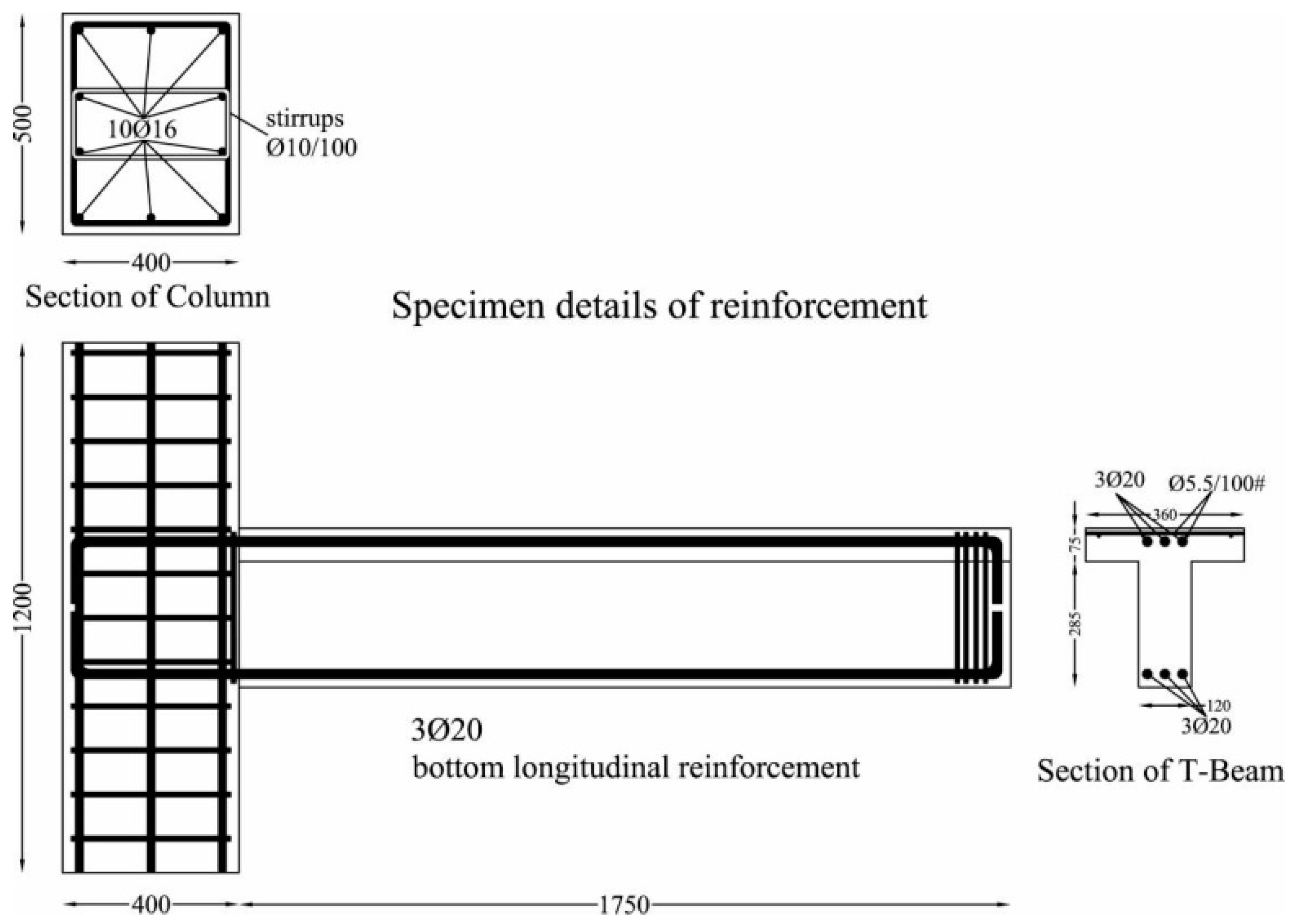
A total of seven reinforced concrete T-beams were tested under cyclic load in the experimental program. Dimensions and reinforcement details are shown in Figure 1. The cross-sections and conventional steel reinforcement details were identical for all specimens. Three 20 mm diameter steel rebars were positioned longitudinally at the top and bottom of the beam section. No stirrups were placed in the beams. The strengthening scheme consisted of high-strength steel fiber strips and a commonly used organic resin. Mechanical anchorages were used in four specimens. Table 1 summarizes the specimens’ properties.
The specimens were cast corresponding to concrete quality C16/20 according to EC2. Ordinary Portland Cement was used with a water to cement (w/c) ratio 0.55. (Mix proportions of the concrete used: concrete IV 32.5 390 kg/m3, water 214.5 kg/m3, sand (0–4 mm) 755 kg/m3, fine aggregate (4–8 mm) 419 kg/m3, and coarse aggregate (8–16 mm) 502 kg/m3.) Three standard cylindrical specimens (150 × 300 mm) for each T-beam were used to measure the concrete strength, the average 28-day compressive strength was 21.6 MPa whereas the standard deviation SD = 2.82 MPa. This corresponds to a concrete with characteristic compressive strength 17 MPa which is very close to the C16/20.
The internal steel reinforcement was made with deformed round bars. The mechanical properties were experimentally determined. More specifically, the yield stress was equal to 530 MPa and the ultimate stress equal to 590 MPa. The modulus of elasticity was measured with strain gauges equal to 200 GPa. The stress–strain curve exhibited an initial elastic region that followed the typical hardening behavior of steel. Finally, in order to ensure the adequate development length, all longitudinal reinforcing bars were bent 90° at the ends of the beams (see Figure 1).
Steel fiber strips that were used for the strengthening system are not commercially available. They were fabricated by the manufacturer specifically for this research project. The strips were based on zinc coated steel cords. Each cord consisted of seven ministrands, and each strand was fabricated by twisting three 0.15 mm diameter high strength steel wires. In total, each strip consisted of 28 cords with an equivalent width equal to 100 mm. The total tension capacity was 24.64 kN with an elastic modulus of 210 GPa. The ultimate tensile strain was recorded as equal to 0.009.
A commercial two component epoxy adhesive was selected to be utilized as a binding material for the application of the SFRP strengthening system. The mechanical characteristics after the curing of the mix at 23 °C and 50% relative humidity, according to the manufacturer, are having a tensile strength of 30 MPa, elongation at break equal to 1.5% and flexural modulus of elasticity 3.8 GPa.
CTB was the control specimen that was tested without strengthening. Six remaining shear deficient beams that were manufactured without stirrups, were strengthened with SFRP strips which were bonded along the shear span. Specimen TB150 was strengthened with 100 mm wide U-shape SFRP uniaxial strips placed at a distance of 150 mm. Specimen TB200 was strengthened with 100 mm wide U-shape SFRP uniaxial strips placed at a distance of 200 mm. No anchoring devices were used for these two specimens. Four last specimens were strengthened with SFRP strips with the use of epoxy resin and mechanical anchors (see Table 1). Specimens TB150L2t and TB150P1b were strengthened beams that utilized a strengthening system with strip spacing of 150 mm and steel L shape or Plate for anchoring device, respectively. Specimens TB200L1t and TB200P2b were strengthened with SFRP strips placed with spacing of 200 mm and anchored with steel L shape and rectangular steel plate. More specifically, the anchoring device of TB200P2b was developed and patented by Aristotle University of Thessaloniki, Department of Civil Engineering, Laboratory for Strength of Materials and Structures. The details of strengthening schemes for each specimen are shown in Table 1.
The investigated anchoring devices have been chosen as representative mechanical systems among the most commonly used for strengthening applications. In addition, through the present study the construction difficulties during the application of these systems is investigated together with their modes of failure that might occur on the anchoring device itself. Finally, the construction detailing and application is realistic for all the investigated anchoring systems due to the existence of the RC slab, which makes the wrapping of the strip nonfeasible.
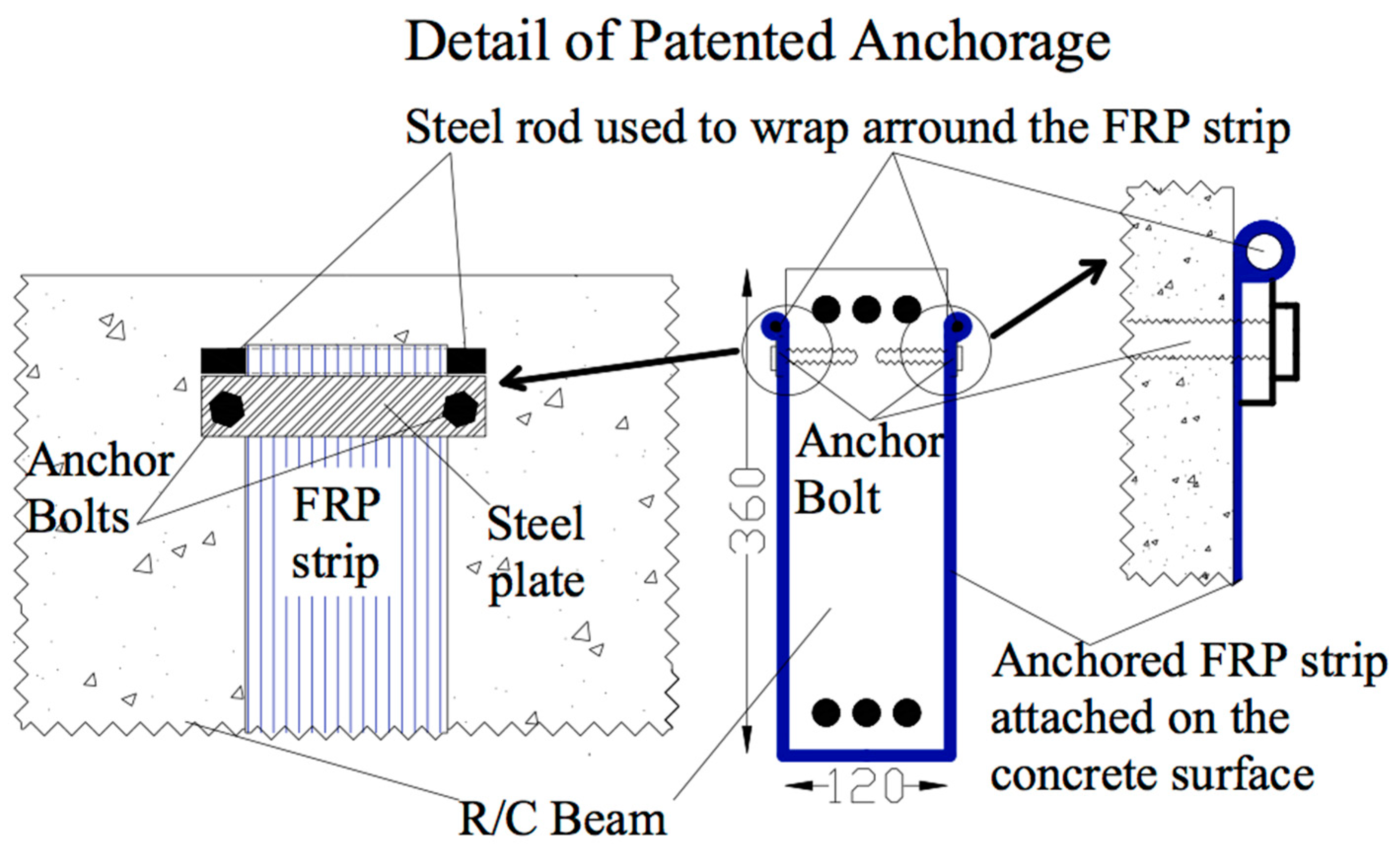
More specifically TB150P1b was strengthened with 100-mm-wide U-shaped SFRP strips spaced at 150 mm. Each U-shaped strip was anchored using a 20 by 5 mm rectangular steel plate secured with a 6-mm bolt. The mechanical anchor used in specimen TB150P1b is the easiest to apply and the most economical. TB150L2t was strengthened with 100-mm-wide U shaped SFRP strips spaced at 150 mm. Each strip was anchored at the bottom of the slab using a 50 × 50 × 5 mm steel angle. Two 8 mm diameter bolts were used to secure the strips. The bolts were positioned through the slab in order to avoid pull-out type failure of the anchors. TB200L1t was strengthened with 100 mm wide U shaped SFRP strips spaced at 200 mm. The strips were anchored at the bottom of the slab using a 50 × 5 mm steel angle. One 8 mm diameter bolt was used to secure the strips. Both bolts were positioned through the slab in order to avoid pull-out type failure of the anchors. This is a similar system to the one used in TB150L2t except that only one bolt was used in each steel plate. In addition, TB200P2b was strengthened with 100 mm wide U shaped SFRP strips spaced at 200 mm. For this specimen two layers of SFRP were utilized. The strips were anchored on the side of the beam just underneath the slab using the innovative device developed at Aristotle University of Thessaloniki. The device consists of a steel rectangular plate and a steel rod. More specifically, the SFRP strip passes under the plate and is wrapped around the rod. Finally, it passes again under the plate which is securely fixed onto the concrete substrate using two steel anchor bolts. The arrangement of the innovative anchoring device is depicted in Figure 2.
Strengthening System Application
The application of the strengthening system took place at least 40 days after casting. Before the application of the strengthening system, the surface of the beam was grinded with an angle grinder to remove all laitance and dirt from the surface. The concrete surface was then cleaned with a steel wire brush and finally compressed air was used to remove concrete dust and dirt that had settled on the beam. This ensured that the concrete surface was clean of contaminants and debris. In addition, the bottom corners were rounded. A first layer of resin was applied on the surface and the SFRP strip was positioned on the resin. Using grooved rollers, it was ensured that no air voids were left in the resin. It should be noted that the specific SFRP strips are not very stiff, and as a result there was no need of prebending them to their final U-shape. The specific SFRP strips were calculated and fabricated by the industry for the present study having geometrical and strength similarities to an equivalent CFRP strip; this is the reason why plastic black cords with negligible stiffness and strength were placed in between each steel cord. Comparing the application of this specific SFRP with an equivalent CFRP strip, it could be said that no difficulties were observed. On the other hand, it is well known from the literature that SFRP strips are much stiffer compared to CFRP, this is why they need to be prebent.
The mechanical anchoring system in specimen TB150P1b consists of a rectangular steel plate and a 6-mm bolt, which is specifically fabricated for usage in concrete. The plates were predrilled in the middle (7-mm hole). Using a drill bit a hole was drilled in the slab. The SFRP strip was applied using resin and subsequently the steel plate was positioned on top of the hole. Finally, the bolt was screwed in the concrete hole through the steel plate and the SFRP, by overpassing the high strength steel cords in order not to damage them.
The same procedure, with some small differences, was followed for the remaining anchored specimens. In the case that steel angles were used and 9-mm bits were used to drill holes throughout the 75 mm deep slab. The bolts were then pushed from the bottom of the slab and were secured with lug nuts on the top of the slab. A 2-mm-thick steel plate was used as a washer on the top (details are shown in Table 1).
3. Experimental Setup
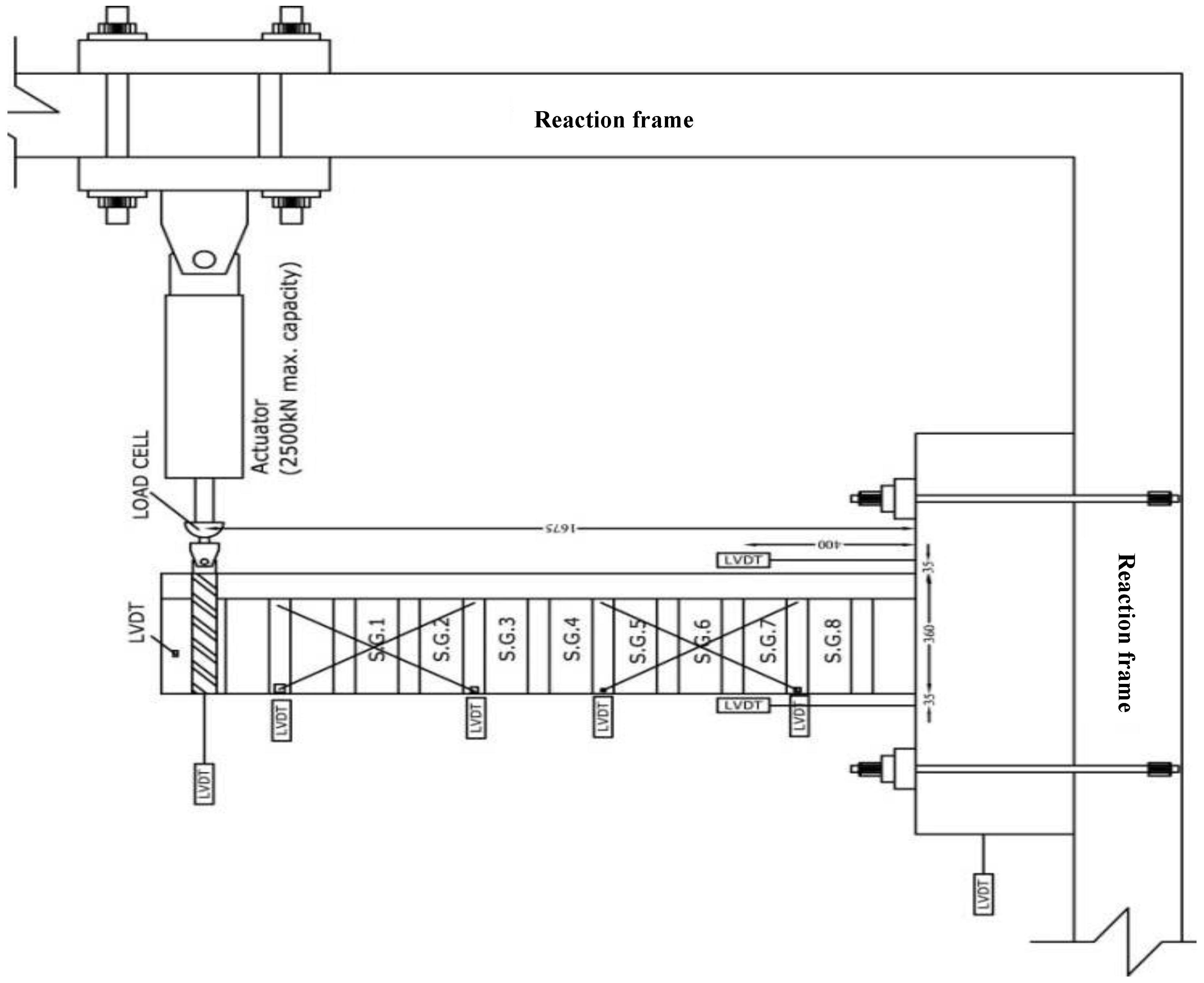
In total, seven cantilever reinforced concrete beams having a T-shape cross-section were fabricated and tested under cycling loading conditions. A schematic view of experimental setup and the arrangement of the measurement devices are shown in Figure 3.
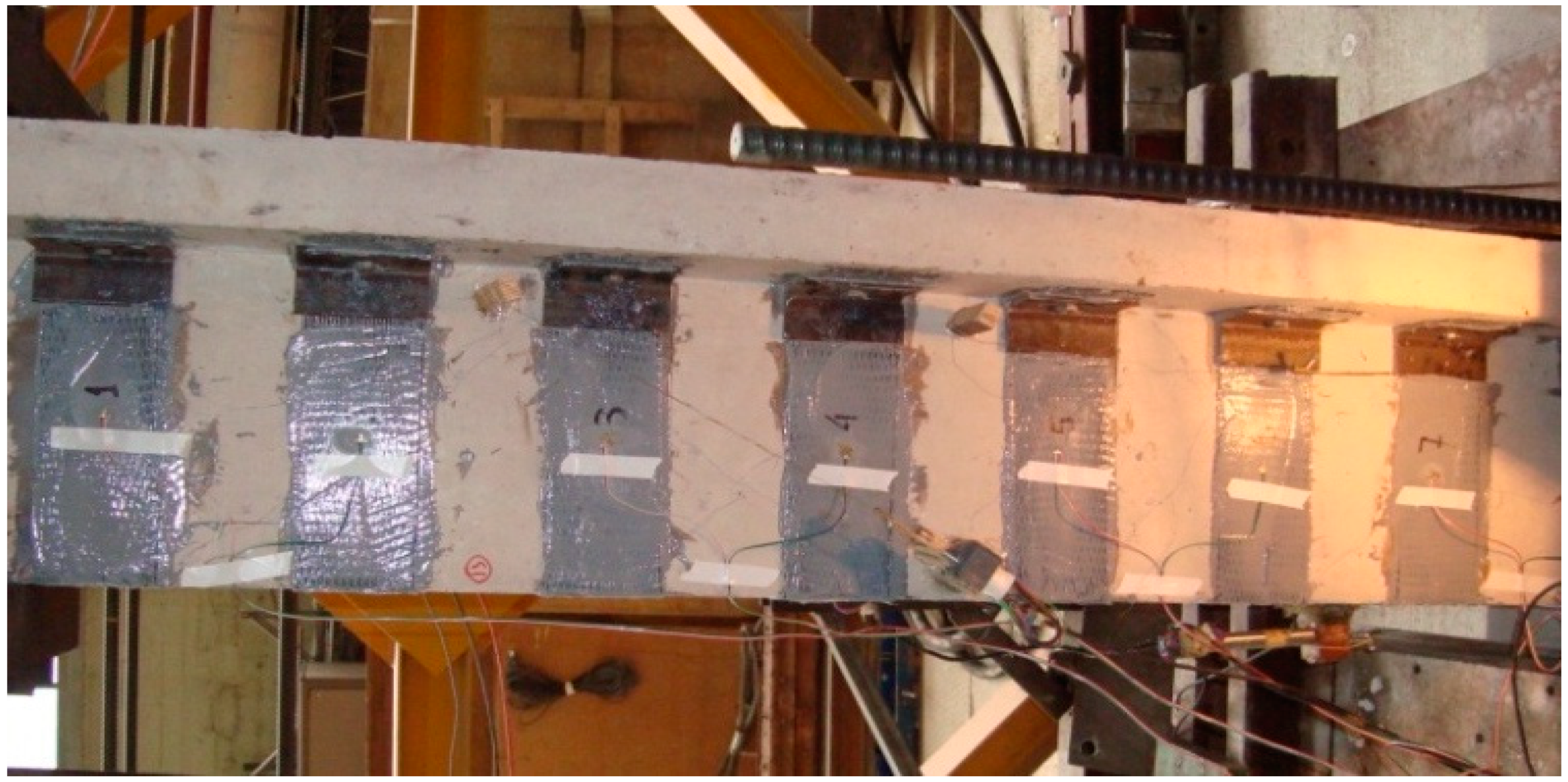
The investigated RC specimens consisted of a T-beam with dimensions 120 by 360 mm with a slab width of 360 mm and a rectangular column with cross-sectional dimensions 400 by 500 mm. The part of the specimen that resembles the column was securely fastened onto the reaction frame. The free end of the beam was attached via a hinge to a 2500 kN capacity hydraulic actuator which was used to apply the cyclic load. The load was controlled with a 1000 kN capacity load cell under deflection control, driven by the MTS controller of the laboratory. After applying three cycles in the elastic region, loading cycles were increased gradually up to failure. The same loading methodology was applied to all specimens. The cyclic loading was imposed at a distance of 1675 mm, from the column (see Figure 3). At this specific point, the beam’s free end deflection was measured using LVDT, together with both uplifts to capture the rotation of the joint. Four additional LVDTs were place diagonally to measure the openings of the diagonal cracks. LVDTs were also positioned perpendicular to the longitudinal axis of the beam to ensure that the beam did not deflect out of plain. Totally 9 displacement recordings were obtained during each test. In addition, SFRP strains were also measured with strain gauges. Strain gauges were attached on 8 consecutive SFRP strips as depicted in Figure 3 and Figure 4. A strain gauge was attached to the mid-height of each SFRP strip along the fiber direction. Finally, the applied load together with 9 LVDT measurements and 8 strains were recorded.
4. Experimental Results and Discussion
CTB was the control specimen and the first to be tested. Due to the fact that no shear reinforcement was used the beam failed in a brittle shear manner. Two relatively big shear cracks initiated on the beam web and propagated until the bottom of the slab. After that point, the crack propagated along the interface between the top of the beam and the bottom of the slab. At failure, the slab separated from the beam. Failure occurred at a maximum load of 37.25 kN. Experimental results, such as maximum shear load, strains, and description of failure modes for all tested specimens, are shown in Table 2. In addition, the photographic documentation of all failed beams is presented at Table 3.
Specimen TB150 suffered, also, a relatively brittle failure. Failure occurred due to delamination of the SFRP strips. More specifically 5 shear cracks initiated at mid-height of the beam, while one of them propagated quite rapidly when the load exceeded the 60 kN threshold to the top and bottom of the beam. The increasing width of the crack resulted in the debonding which initiated at the location of the crack and propagated to the top of the SFRP strip. A similar failure pattern was observed from the test of specimen TB200. The ultimate bearing capacity of TB150 is 73.2 kN whereas TB200 failed for a maximum load equal to 60 kN. The debonding mode of failure prevailed for both strengthened beams with no anchoring device. As expected, the spacing of the SRP strips plays an important role for increasing the ultimate shear capacity under cyclic loading. The present study did not focus on the delamination of SFRP strips. The nonanchored specimens were utilized for comparison purposes with the anchored strengthened T-beams in order to prove their efficiency under cyclic loadings. In general, the delamination of composite strips from concrete substrate has been extensively investigated and quantified in the past. The debonding mechanism of SFRP strips is similar with CFRP. In the literature Anil et al. [7] and Tanarslan et al. [32] have conducted similar tests without anchoring devices using CFRP. By comparing their results with the present study, it could be said that the delamination of SFRP occurred slightly after the delamination of CFRP strips. The developed strains on SFRP strip are at the rang of 4500 με. Nevertheless, this is only an indication since it is more than well known that the critical aspects of the debonding mode of failure are the surface preparation and the strength of the concrete.
Several shear cracks were initiated in specimen TB150P1b both at +45 and at −45 degrees, due to the cyclic load. The most considerable shear crack initiated at a distance of approximately 700 mm from the fixed end of the beam. The crack propagated through the cycles and resulted in a local debonding of the SFRP strip due to an increasing crack width. Following this, the debonding propagated to the top of the beam up until the mechanical anchor. At that point the anchor failed due to the pull-out of the bolt. As it can be seen in Table 3 that the pull-out failure of the anchor resulted in the failure of the second strip that was resisting the shear crack. The failure of the second anchor resulted in a delamination of the strips and subsequently the beam failed.
In specimen TB150L2t a similar shear crack pattern to TB150P1b was observed. The most significant shear crack occurred at a distance of 850 mm from the fixed end of the beam. The crack propagated throughout the loading cycles and was bridged by two SFRP strips. However, the failure of the beam was not the typical brittle shear failure that occurred in TB150P1b. The first sign of failure was yielding of the longitudinal rebars. Finally, the SFRP strips fractured at the corners of the steel angle due to increasing stresses. It should be noted that the double bolt through the slab anchoring system did not show any signs of failure. It has also to be pointed out that the longitudinal reinforcement consisted of three 20 mm bars, for a cross-section of 120 × 360 mm, with a corresponding reinforcement ratio of 2.42%. Despite the fact that no stirrups were used, the external shear reinforcement (anchored-SFRP) strengthened the beam adequately and resulted in a ductile flexural failure.
Specimen TB200L1t which is quite similar to specimen TB150L2t (with the exception of larger distance between the SFRP strips and one instead of two anchoring bolts) indicated a similar performance to TB150L2t. Initially the specimen was tested up to 91.2 kN. The test was stopped due to signs of premature beam–column joint failure. The joint was subsequently repaired, and the specimen was retested. During the second test shear cracks started forming on the beam and the experiment was finally stopped since the crack width was increasing resulting to a decrease of the shear capacity of the beam. The ultimate load that was recorded was equal to 115 kN. The single bolt through the slab anchoring system did not show any signs of failure. Despite the larger distance between the SFRP strips the anchoring system proved to perform equally well to TB150L2t.
Finally, specimen TB200P2b was also tested under cyclic displacement control conditions. The maximum recorded load of 120 kN was the highest recorded load in all specimens. For this specimen the anchoring system was attached on the face of the beam. Shear cracks begin to propagate due to cyclic loading condition. No sign of bending failure was observed. The increase of the width of shear cracks resulted to the final failure of the beam due to the pull out of the anchoring bolts from the concrete.
The ultimate bearing capacity was observed for specimen TB200P2b, a strengthened T-section beam where the innovative patented anchoring device, was employed. The bearing capacity of that beam was measured equal to 120 kN. The mode of failure as seen at the final row of Table 3, initiated by the development of severe shear cracks and the pull out of an anchor bolt followed. It was by chance that a part of the shear crack passed through the bolt’s hole. It is also interesting that the axial spacing of the SFRP strips is 200 mm and not 150 mm. It can be said that the efficient anchoring of SFRP strips may lead to a further increase of the strengthened bearing capacity.
Maximum shear loads as well as maximum deflections are presented in Table 4. Also, in Table 4 percentages of shear force and deformation increase as compared to the control specimen are presented. An examination of the values listed in this table lead to the conclusion that the addition of SFRP shear reinforcement results in an increase of strength, regardless of whether SFRP strips were anchored or not. However, the increase was significantly more pronounced when SFRP strips were anchored on the T-section specimens. More specifically, anchored specimens can result in an increase of shear strength that exceeds 200%, while nonanchored specimens result in increases that are lower than 100%, compared with a T-section beam with no internal shear reinforcement. Therefore, we can see that the addition of mechanical anchoring systems (i) can almost double the shear strength of the strengthening system and (ii) can drive the mode of failure to a more ductile manner. This is the reason that the imposed horizontal displacement was increased more than 800% for beam TB150L2t and almost 450% for beam TB200P2b.
Furthermore, the calculated maximum shear capacities of each strengthened beam are presented in Table 2. In order to predict ultimate shear force, the strain measurements developed on the SFRP strips, intersected by the major shear crack, were taken under consideration. These strain values are presented in Table 2. The predicted values are very close to the experimentally measured (see Table 4). The calculated shear forces are further discussed in more detail in Section 5.
The results obtained in the study are further discussed with equivalent results from the literature. Anil et al. [7] and Tanarslan et al. [32] have conducted similar experimental investigation with the difference of strengthening material. Both studies from the literature have investigated CFRP strips whereas we utilized SFRP strips. For all studies the employed anchoring devices are mechanical with slight differences concerning the final geometric arrangement. All studies have demonstrated that when an efficient anchoring device is used, the preliminary debonding mode of failure is avoided. In addition, when CFRP strips are combined with anchoring devices, the mode of failure is driven to the CFRP strip, close to beam corners, or near the anchoring device where there is stress concentration. On the other hand, when SFRP strip are utilized with efficient anchoring devices, this premature mode of failure is avoided. The authors believe that the lateral stiffness of SFRP strips compared to CFRP strips is bigger, a parameter that could explain this phenomenon. Furthermore, when SFRP are used, the mode of failure is driven to the anchoring device, a more complicated mode of failure with extensive diversities. By comparing the results obtained in this study together with the results from the literature, it is demonstrated that the overall behavior of the developed and patented anchoring device that was utilized together with SFRP strips was efficient. Finally, the present study is the first in the literature that investigates SFRP strips for strengthening T-section RC beams under cyclic loading conditions, when different anchoring devices are combined with applied SFRP strips.
4.1. Deflections—Hysteretic Energy
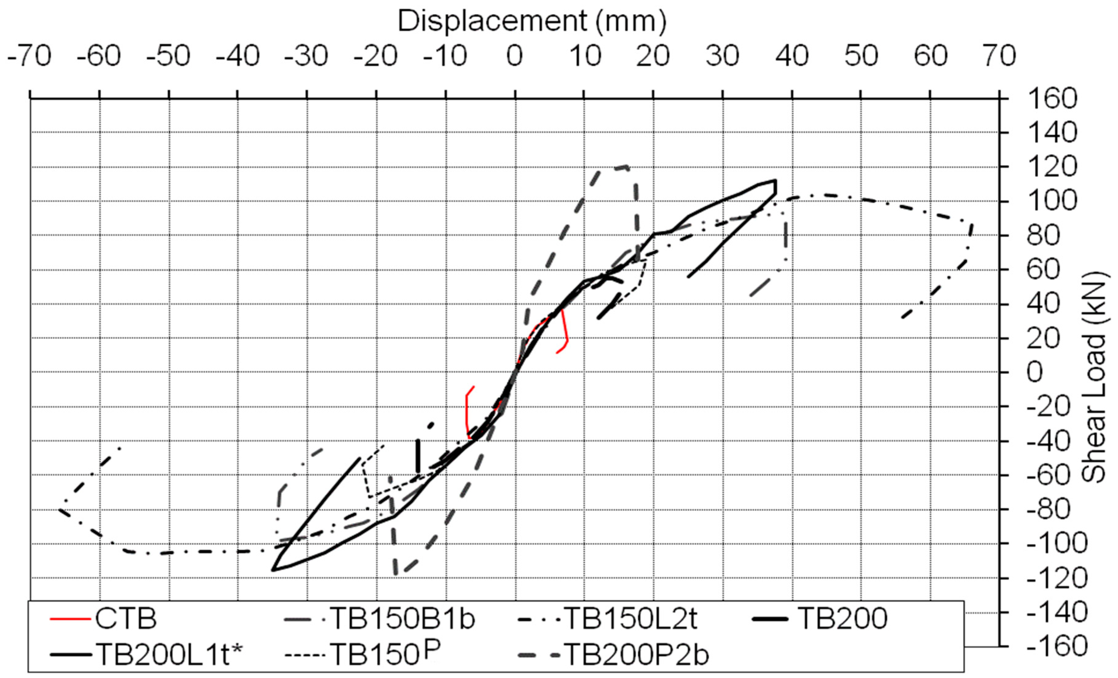
Load–deflection response envelopes for all the specimens are shown in Figure 5. It is observed that nonanchored SFRP strips failed due to delamination in a brittle fashion. On the contrary, anchored specimens exhibited a significantly more ductile behavior. It can be seen that the maximum deflections for anchored specimens are significantly higher (40–50 mm) compared to specimens with no anchorage (less than 20 mm).
From an examination of the deformation percentage compared to the control specimen that is listed in Table 4 we can see that the addition of mechanical anchors renders the specimens significantly more ductile. More specifically, the use of SFRP bonded strips results in an increase of maximum deflections of approximately 186% while the addition of mechanical anchorage in the previously mentioned bonded strips results in a maximum increase of deflections of more than 800%. The aforementioned observations are valid in the literature [7,32] as well. The increase of the shear capacity together with the maximum imposed deflection was observed for both studies. The percentage of increase for both cases is comparable but slightly smaller. More specifically, Beam-3, Beam-4, and Beam-5 [7] have a shear increase capacity at the range of 120% combined with an average increase of the maximum imposed displacement equal to 300%. Similarly, Spec-3 to Spec-6 [32] obtained percentages smaller than Anil et al.
During a high magnitude earthquake, structures are expected to enter an elasto-plastic range and hysteresis loops can provide an understanding for analysis of seismic elastoplastic response. The dissipated energy is the area enclosed by the hysteresis loop (see Table 3) and represents the structural element’s capacity to mitigate the earthquake effect inelastically which causes excessive cracking and permanent deformation.
In reinforced concrete structures strengthened with externally bonded FRP materials, the externally bonded FRP can dissipate energy due to fiber deformation, slip, and gradual fracture. Load–deflection hysteresis loops of all tested beams are shown in Table 3. It can be observed that for all beams, the dissipated energy in the first cycles was considerably smaller than in subsequent cycles. This phenomenon occurred because extensive crack propagation and thus increased deflections occurred during the final stages of the experiment. The variation in the energy dissipation is due to different strengthening schemes, anchoring devices, etc.
From the load displacement loops for each specimen and also for similar specimens found in the literature we calculated the energy dissipated by specimens [7,32]. The area under the load displacement curves shows the dissipated energy in units of kNmm (Joule). The dissipated energy during the loading cycles was calculated using the trapezoidal rule to determine the area within the load–deflection hysteresis loop. The values of total dissipated energy (TDE) of each specimen are presented in Table 5. In addition, the increase compared to the control specimen is shown as a ratio. The third row in the Table 5 shows the increase in terms of a strengthened specimen with SFRP strips that were not anchored.
It can be identified that strengthened specimens exhibit at least double hysteretic energy compared to the control specimen. It is also clear, that the addition of an anchoring device results in an even more pronounced increase of hysteretic energy. More specifically, the use of anchoring systems results in at least five times higher energy compared to nonanchored strengthened specimens. Therefore, anchored specimens were able to absorb considerable amounts of energy up to failure.
4.2. FRP Strains
In order to evaluate the shear resistance contribution of the strengthening applications, strain gages were attached at mid-height of each SFRP strip along the direction of the fibers. It should be mentioned that the reported strains for each specimen are the recorded strains from the strips that bridged the shear crack. Additionally, the number of SFRP strips that resisted the formed shear crack is shown in Table 2.
The highest recorded strains were obtained for specimen TB150L1t*. In this case, the maximum, average recorded strains exceeded 6500 μm/m. In contrast, the specimens that were strengthened with SFRP without the use of mechanical anchors, maximum strains were kept to significantly lower values (2500 με). This observation emphasizes that the use of mechanical anchors results in better utilization and performance of the strengthening material. Specimens TB150 and TB200 failed due to debonding of the SFRP strip, so the maximum recorded SFRP strain indicate values lower than the maximum effective strain. However, the recorded strain could be used to obtain shear performance related analytical expressions for the anchored SFRP strips (see Table 2).
ACI 440-08 (ACI 2008) and Fib ((fib) 2001) report that the maximum effective strain should be limited to 0.004 mm/mm, whereas Eurocode (1998-3:2005 2005) [34,35,36] does not provide a specific numerical limit but the effective strain is calculated using formulas that depend upon the strengthening scheme. The rather small strain value is based on the assumption that typical composite materials do not cope well with stress concentrations that occur at the lower corners of the beams. However this is not necessarily the case with steel fibers that are tougher than carbon and glass fibers. It should be noted that the steel fibers did not fail at the bottom corners of the beams.
Using the recorded SFRP strains the material exploitation index (MEI) was calculated for each specimen and is presented in Table 6. The index was calculated as a ratio of maximum recorded strain to ultimate measured strain (0.9%) of the SFRP strips obtained from coupon testing. The index varied from 0.22 to 0.74. It is evident that MEI of SFRP strips is bigger when an anchoring device is used. The maximum MEI was 0.29 for nonanchored specimens while it was at least 0.44 for anchored specimens. At this point it has to be mentioned that TB200P2b was strengthened using two layers of SFRP strips, thus resulting to relatively small strain measurements. For this specimen the average strain measurement for two layers of SFRP was recorded equal to 3980 μstrain which resulted to a MEI equal to 0.44. It is evident that the addition of a second layer does not result in an increase of the material exploitation.
5. Calculation of Maximum Shear Force from Experimental Strains
Based on the strain recordings, we calculated the maximum calculated shear force Vcal, which is compared to the experimental maximum shear force Vmax. Values (Vcal) were calculated using the equation
where Vc,exp is the experimental shear force of the control specimen (CRB), while the Vf,cal is calculated as
where,
and εf1,exp, εf2,exp, are the maximum recorded strains in the two strips that bridge the shear crack (see Table 5). Note that we did not use the common relationship that uses the ratio df/Sf in order to calculate the number of strips that contribute to the shear capacity of the externally bonded fiber reinforced strips.
In other words, it was assumed that a shear crack in concrete is resisted by exactly two consecutive FRP strips (their strains are reported in Table 2 and Table 6). It is noted that this assumption was confirmed from all experiments.
In almost all cases the calculated value is lower than the recorded by a relatively small margin. More specifically, the ratio Vmax/Vcal varies from 1% to 19% with an average value of 10%. The strain was measured using a strain gage positioned approximately in the center of the SFRP strips in terms of width and height; therefore, we were not able to capture the absolute maximum strain in all cases. For specimen TB150L2t the calculated shear force was 19% lower than the recorded value. This difference could be explained from a possible error in strain recordings. More specifically, as mentioned previously, the use of only one strain gage may have resulted in a lower recording than the actual maximum. However, one could claim in general that the assumption that the shear strength that results from the addition of the FRP strips could be calculated from the stress of the FRP strips bridging the crack, holds true.
6. Conclusions
An analysis of the presented experimental data leads to the following conclusions:
A strengthening system that combines high-strength steel fibers together with organic epoxy is experimentally investigated under cyclic loading conditions. This system was proven equivalent to the existing systems when it is combined with an efficient anchoring device. The following comments summarize the most important conclusions of the present study.
- SFRP strips can be used for shear strengthening of reinforced concrete beams instead of CFRP or GFRP.
- Mechanical anchors greatly improve the performance of shear strengthening SFRP strips.
- The innovative patented anchoring device performed exceptionally well under cyclic loading conditions.
- Maximum deflections, recorded maximum SFRP strains, and total dissipated energy are significantly higher for anchored specimens.
- The average value calculated from maximum strains recorded in the strips that resisted the shear crack can be effectively used to calculate the maximum shear resisting force, Vf.
- The anchoring system has a significantly more pronounced effect on the performance of the beams and the mode of failure than the spacing of the strips.
- Lack of mechanical anchoring results in premature delamination of the SFRP strips, and thus an undesirable SFRP material performance.
7. Patents
G. C. Manos, K. Katakalos, and V. Kourtides, “Construction Systeme for Strengthening an Existing Structure with Tension Sheets and a Respective Anchoring Device and Method” Patent No: EP2336455-(A1), 2011.
Author Contributions
K.K., G.M., and C.P. had equal contribution. In addition, K.K. wrote the manuscript.
Funding
Partial financial support for this investigation was provided by the Hellenic Earthquake Planning and Protection Organization (EPPO). The anchoring device employed in this study, is patented under patent no. WO2011073696, which is managed by the Research Committee of Aristotle University.
Acknowledgments
Steel fibers are not commercially available and were provided for the present study by Bekaert Industries. The epoxy resins were provided by Sika Hellas under the code name SikaDur330.
Conflicts of Interest
The authors declare no conflicts of interest.
References
- Minnaugh, P.L.; Harries, K.A. Fatigue behavior of externally bonded steel fiber reinforced polymer (SFRP) for retrofit of reinforced concrete. Mater. Struct. 2009, 42, 271–278. [Google Scholar] [CrossRef]
- Katakalos, K.; Papakonstantinou, C. Fatigue of Reinforced Concrete Beams Strengthened with Steel Reinforced Inorganic Polymers. J. Compos. Constr. 2009, 13, 103–112. [Google Scholar] [CrossRef]
- Mossallam, A.S. Innovative Systems for Seismic Repair and Rehabilitation of Structures, Design and Applications; Sage Publishing Company: Southend, CA, USA, 2000. [Google Scholar]
- Rousakis, T.C.; Saridaki, M.E.; Mavrothalassitou, S.A.; Hui, D. Utilization of hybrid approach towards advanced database of concrete beams strengthened in shear with FRPs. Compos. Part B 2016, 85, 315e335. [Google Scholar] [CrossRef]
- Thermou, G.E.; Katakalos, K.; Manos, G.C. Experimental investigation of substandard RC columns confined with SRG jackets under compression. Compos. Struct. 2018, 184, 56–65. [Google Scholar] [CrossRef]
- Hawileh, R.; Abdalla, J.A.; Naser, M.Z.; Tanarslan, M. Finite element modeling of shear deficient RC beams strengthened with NSM CFRP rods under cyclic loading. Spec. Publ. 2015, 301, 1–18. [Google Scholar]
- Anil, O. Strengthening of RC T-section beams with low strength concrete using CFRP composites subjected to cyclic load. Constr. Build. Mater. 2008, 22, 2355–2368. [Google Scholar] [CrossRef]
- Arduini, M.; Di Tommaso, A.; Nanni, A. Brittle failure in FRP plate and sheet bonded beams. ACI Struct. J. 1997, 94, 363–370. [Google Scholar]
- Khalifa, A.; Nanni, A. Rehabilitation of Rectangular Simply Supported RC Beams with Shear Deficiencies Using CFRP Composites. Constr. Build. Mater. 2002, 16, 135–146. [Google Scholar] [CrossRef]
- Manos, G.C.; Katakalos, K.; Kourtides, V. The Influence of Concrete Surface Preparation When Fiber Reinforced Polymers with Different Anchoring Devices Are Being Applied for Strengthening R/C Structural Members. Appl. Mech. Mater. 2011, 82, 600–605. [Google Scholar] [CrossRef]
- Nanni, A. Flexural behavior and design of RC members using FRP reinforcement. J. Struct. Eng. 1993, 119, 3344–3359. [Google Scholar] [CrossRef]
- Papakonstantinou, C.G.; Katakalos, K. Flexural behavior of reinforced concrete beams strengthened with a hybrid inorganic matrix—Steel fiber retrofit system. Struct. Eng. Mech. 2009, 31, 567–585. [Google Scholar] [CrossRef]
- Casadei, P.; Nanni, A.; Alkhrdaji, T.; Thomas, J. Performance of double-T prestressed concrete beams strengthened with steel reinforcement polymer. Adv. Struct. Eng. 2005, 8, 427–441. [Google Scholar] [CrossRef]
- Huang, X.; Birman, V.; Nanni, A.; Tunis, G. Properties and potential for application of steel reinforced polymer and steel reinforced grout composites. Compos. Part B Eng. 2005, 36, 73–82. [Google Scholar] [CrossRef]
- Mitolidis, G.J.; Salonikios, T.N.; Kappos, A.J. Test results and strength estimation of R/C beams strengthened against flexural or shear failure by the use of SRP and CFRP. Compos. Part B Eng. 2012, 43, 1117–1129. [Google Scholar] [CrossRef]
- Rousakis, T.C.; Saridaki, M.E. Advanced database of concrete beams strengthened in shear with FRPs. In Proceedings of the Twenty-Second Annual International Conference on COMPOSITES/NANO-ENGINEERING (ICCE-22), Saint Julian’s, Malta, 13–19 July 2014; pp. 13–19. [Google Scholar]
- Thermou, G.E.; Katakalos, K.; Manos, G.C. Influence of the cross section shape on the behaviour of SRG-confined prismatic concrete specimens. Mater. Struct. 2016, 49, 869–887. [Google Scholar] [CrossRef]
- Rousakis, T.C.; Karabinis, A.I.; Kiousis, P.D.; Tepfers, R. Analytical modelling of plasticbehaviour of uniformly FRP confined concrete members. J. Compos. Part B Eng. 2008, 39, 1104–1113. [Google Scholar] [CrossRef]
- Thermou, G.E.; Katakalos, K.; Manos, G.C. Concrete confinement with steel-reinforced grout jackets. Mater. Struct. 2015, 48, 1335–1376. [Google Scholar] [CrossRef]
- Manos, G.C.; Katakalos, K. The Use of Fiber Rein- forced Plastic for the Repair and Strengthening of Existing Reinforced Concrete Structural Elements Damaged by Earthquakes. In Fiber Reinforced Polymer—The Technology Applied for Concrete Repair; Masuelli, M.A., Ed.; IntechOpen: London, UK, 2013. [Google Scholar]
- Barton, B.; Wobbe, E.; Dharani, L.R.; Silva, P.; Birman, V.; Nanni, A.; Alkhrdaji, T.; Thomas, J.; Tunis, G. Characterization of reinforced concrete beams strengthened by steel reinforced polymer and grout (SRP and SRG) composites. Mater. Sci. Eng. A 2005, 412, 129–136. [Google Scholar] [CrossRef]
- Prota, A.; Kah Yong, T.; Nanni, A.; Pecce, M.; Manfredi, G. Performance of shallow reinforced concrete beams with externally bonded steel-reinforced polymer. ACI Struct. J. 2006, 103, 163–170. [Google Scholar]
- Saadatmanesh, H.; Malek, A.M. Design guidelines for flexural strengthening of RC beams with FRP plates. J. Compos. Constr. 1998, 2, 158–164. [Google Scholar] [CrossRef]
- Shahawy, M.; Beitelman, T.E. Static and fatigue performance of RC beams strengthened with CFRP laminates. J. Struct. Eng. 1999, 125, 613–621. [Google Scholar] [CrossRef]
- Wobbe, E.; Silva, P.; Barton, B.L.; Dharani, L.R.; Birman, V.; Nanni, A.; Alkhrdaji, T.; Thomas, J.; Tunis, G. Flexural Capacity of RC Beams Externally Bonded with SRP and SRG; Society for the Advancement of Material and Process Engineering: Covina, CA, USA, 2004; pp. 2995–3002. [Google Scholar]
- Chen, J.F.; Teng, J.G. Shear Capacity of Fiber-Reinforced Polymer Strengthened Reinforced Concrete Beams: Fiber Reinforced Polymer Rupture. J. Struct. Eng. 2003, 129, 615–625. [Google Scholar] [CrossRef]
- Gao, P.; Gu, X.; Mosallam, A.S. Flexural behavior of preloaded reinforced concrete beams strengthened by prestressed CFRP laminates. Compos. Struct. 2016, 157, 33–50. [Google Scholar] [CrossRef]
- Manos, G.C.; Katakalos, K.; Kourtides, V. Study of the Anchorage of Carbon Fiber Plastics (CFRP) Utilized to Upgrade the Flexural Capacity of Vertical R/C Members. In Proceedings of the 14th World Conference on Earthquake Engineering (WCEE), Beijing, China, 12–17 October 2008; pp. 1079–1095. [Google Scholar]
- Manos, G.C.; Katakalos, K.; Kourtides, V. Cyclic Behavior of a Hybrid Anchoring Device Enhancing the Flexural Capacity and Ductility of an R/C Bridge-Type Pier Strengthened with CFRP Sheets. J. Civil Eng. Res. 2013, 3, 52–64. [Google Scholar]
- Manos, G.C.; Katakalos, K.; Koidis, G.; Papakonstantinou, C.G. Shear Strengthening of R/C Beams with FRP Strips and Novel Anchoring Devices. J. Civil Eng. Res. 2012, 2, 73–83. [Google Scholar] [CrossRef]
- Tanarslan, H.M.; Altin, S. Behavior of RC T-section beams strengthened with CFRP strips, subjected to cyclic load. Mater. Struct. 2010, 43, 529–542. [Google Scholar] [CrossRef]
- Mosallam, A.S. Evaluation and construction of composite strengthening systems for the Sauvie Island Bridge. In Proceedings of the 2nd International Conference on FRP Composites in Civil Engineering—CICE 2004, Adelaide, Australia, 8–10 December 2004; pp. 715–723. [Google Scholar]
- Eurocode 8—Design of Structures for Earthquake Resistance—Part 3: Assessment and Retrofitting of Buildings; 1998-3:2005; CEN: Brussels, Belgium, 2005; pp. 35–55.
- ACI. Guide for the Design and Construction of Externally Bonded FRP Systems for Strengthening Concrete Structures; ACI 440.2R-08; American Concrete Institute: Farmington Hills, MI, USA, 2008; p. 45. [Google Scholar]
- FIB. Externally Bonded FRP Reinforcement for RC Structures; Bulletin No. 14; FIB: Lausanne, Switzerland, 2001. [Google Scholar]
- Mosallam, A.S.; Bayraktar, A.; Elmikawi, M.; Pul, S.; Adanur, S. Polymer composites in construction: An overview. SOJ Materials Science & Engineering. Available online: https://escholarship.org/uc/item/5xf7s8nj#main (accessed on 4 April 2019).
Figure 1.
Specimen details and reinforcement.

Figure 2.
Arrangement of the patented anchoring device [EP2336455, 2011].

Figure 3.
Experimental setup.

Figure 4.
Specimen TB200L1t.

Figure 5.
Load–deflection envelope curves.


Table 1.
Specimen details.
| Specimen | Strengthening Material | Anchoring System | FRP Width (mm) | FRP Distance (mm) | Schematic (Setup/Loading) |
|---|---|---|---|---|---|
| CTB | No | No | N/A | N/A |  |
| Τ150 | SFRP (1 Layer) | No | 100 | 150 |  |
| Τ200 | SFRP (1 Layer) | No | 100 | 200 | |
| TB150L2t | SFRP (1 Layer) |  | 100 | 150 |  |
| TB200L1t | SFRP (1 Layer) |  | 100 | 200 | |
| TB150P1b | SFRP (1 Layer) |  | 100 | 150 | |
| TB200P2b | SFRP (2 Layers) |  | 100 | 200 | |
Table 2.
Experimental results.
| Specimen | Anchoring Device | Max Shear Force Vmax (kN) | No SFRP Strips from the Crack | Strain of 1st SFRP Strip (μStrain) | Strain of 2nd SFRP Strip (μStrain) | Calculated Shear Force from SFRP Strips (kN) | Calc. Total Shear Force Vcal (kN) | Failure Mode |
|---|---|---|---|---|---|---|---|---|
| (1) | (2) | (3) | (4) | (5) | (6) | (7) | (8) | (9) |
| CTB | - | 37.25 | 0 | - | - | 0 | 37.25 | Shear Crack |
| TB150 | No | 73.2 | 2 sg4–5 | 5075 | 245 | 26.46 | 63.71 | Delamination |
| TB200 | No | 58.3 | 1 sg5 | 4010 | - | 19.94 | 57.19 | Delamination |
| TB150 L2t | L-shape 50 × 5 2 bolts 8 mm M8.8 through slab | 106.7 | 2 sg2–3 | 5180 | 5160 | 51.42 | 88.67 | Shear Crack Yield of longitu bars |
| TB200 L1t | L-shape 50 × 5 1 bolt 8 mm M8.8 through slab | 91.2 | 2 sg3–4 | 7790 | 3995 | 58.60 | 95.85 | Failure of joint |
| TB200 L1t | 115 | 2 sg5–6 | 10035 | 3330 | 66.46 | 103.71 | Shear Crack | |
| TB150Β1b | plate 20 × 5 1 bolt HILTI HUS 6mm | 95.5 | 2 sg3–4 | 5455 | 3855 | 46.30 | 83.55 | Shear Crack Anchor bolt pull out |
| TB200 P2b | Patented AUTh 2 bolts HILTI HUS 8 mm | 120 | 2 sg1–5 | 4960 | 3000 | 79.17 | 116.42 | Shear Crack Anchor bolt pull out |
Table 3.
Load–deflection curves together with modes of failure for each beam.
| Specimen | Load–Deflection Curves | Modes of Failure |
|---|---|---|
| CTB |  |  |
| TB150 |  |  |
| TB200 |  |  |
| TB150 L2t |  |  |
| TB200 L1t |  |  |
| TB150Β1b |  |  |
| TB200 P2b |  |  |
Table 4.
Percentage of shear force and deformation increase compared to control specimen.
| Specimen | CΤB | TB150 | TB200 | TB150L2t | TB200L1t | TB200L1t | TB150P1b | TB200P2b |
|---|---|---|---|---|---|---|---|---|
| Recorded Maximum Shear (kN) | 37.25 | 73.2 | 58.3 | 106.7 | 91.2 | 115 | 95.5 | 120 |
| % Shear increase compared to control specimen | 0 | 96.5 | 56.5 | 186.4 | 144.8 | 208.9 | 156.4 | 222.1 |
| Calculated maximum deformation (mm) | 7 | 20 | 15 | 66 | 29,5 | 38 | 37 | 38 |
| % deformation increase compared to control | 0 | 185.7 | 114.3 | 842.9 | 321.4 | 442.9 | 425.6 | 442.9 |
Table 5.
Total dissipated energy.
| Details | No SRP | Nonanchored SRP | Anchored SRP | ||||
|---|---|---|---|---|---|---|---|
| Specimen ID | CΤB | TB150 | TB200 | TB150L2t | TB200L1t | TB150P1b | TB200P2b |
| TDE (kNmm=joule) | 316 | 801 | 701 | 15114 1 | 6271 | 3862 | 4569 |
| Ratio of energy increase compared to CTB | 1.00 | 2.53 | 2.22 | 47.83 | 19.84 | 12.22 | 14.46 |
| Ratio of energy increase compared to TB200 | 0.45 | 1.14 | 1.00 | 21.56 | 8.95 | 5.51 | 6.52 |
1 Flexural failure.
Table 6.
Material exploitation index (MEI) and shear force predictions.
| Specimen | CΤB | TB150 | TB200 | TB150L2t | TB200L1t | TB150P1b | TB200P2b * |
|---|---|---|---|---|---|---|---|
| 1st strip strain (μstrain) | - | 5075 | 4010 | 5180 | 10035 | 5455 | 4960 |
| 2nd strip strain (μstrain) | - | 245 | 130 | 5160 | 3330 | 3855 | 3000 |
| Material Exploitation Index (MEI) | - | 0.29 | 0.22 | 0.57 | 0.74 | 0.55 | 0.44 |
| Maximum Recorded Shear Force Vmax (kN) | 37.25 | 73.2 | 58.3 | 106.7 | 115 | 95.5 | 120 |
| Calculated Shear Force Vcal (kN) | - | 64.06 | 57.5 | 89.36 | 103.7 | 84.17 | 117.49 |
| Vmax/Vcal | - | 1.14 | 1.01 | 1.19 | 1.11 | 1.13 | 1.02 |
* two layers of SFRP were utilized.
© 2019 by the authors. Licensee MDPI, Basel, Switzerland. This article is an open access article distributed under the terms and conditions of the Creative Commons Attribution (CC BY) license (http://creativecommons.org/licenses/by/4.0/).
Share and Cite
MDPI and ACS Style
Katakalos, K.; Manos, G.; Papakonstantinou, C. Seismic Retrofit of R/C T-Beams with Steel Fiber Polymers under Cyclic Loading Conditions. Buildings 2019, 9, 101. https://0-doi-org.brum.beds.ac.uk/10.3390/buildings9040101
AMA Style
Katakalos K, Manos G, Papakonstantinou C. Seismic Retrofit of R/C T-Beams with Steel Fiber Polymers under Cyclic Loading Conditions. Buildings. 2019; 9(4):101. https://0-doi-org.brum.beds.ac.uk/10.3390/buildings9040101
Chicago/Turabian StyleKatakalos, Konstantinos, George Manos, and Christos Papakonstantinou. 2019. "Seismic Retrofit of R/C T-Beams with Steel Fiber Polymers under Cyclic Loading Conditions" Buildings 9, no. 4: 101. https://0-doi-org.brum.beds.ac.uk/10.3390/buildings9040101
Note that from the first issue of 2016, this journal uses article numbers instead of page numbers. See further details here.