1. Introduction
Many industrial processes are based on pumping or compressing liquids or gases. Such processes include, for example waste-water purification plants based on aeration compression, heating, ventilation, air conditioning and refrigeration (HVACR) systems based on liquid chiller compression and sub-sea gas compression units helping to utilize the full potential of subsea gas fields. A common factor for these processes is that the actuator, for example, a compressor, pump or blower, benefits from the use of very high rotational speeds of up to several hundred thousand rotations per minute. The high rotational speed places extra demands on the rotor suspension. Non-contact active magnetic bearings (AMBs), as a suspension solution, provide oil-free, frictionless and maintenance-free operation compared to competing bearing technology such as roller or journal bearings [
1]. The low-efficiency gearbox between the electrical machine and actuator can be removed by integrating the frequency converter driven high-speed electrical machine with the magnetic bearing suspension on the same shaft as the actuator. The result is increased overall efficiency, higher power density and smaller size [
2].
Active control of a magnetically suspended electrical machine is based on knowledge of the shaft displacement from the center point of the mechanical air gap. In magnetic bearing applications, rotor position measurement has typically been based on eddy current, inductive, or capacitive measurement principles [
3]. The cost of non-contact industrial sensor solutions using eddy current sensing technology can, however, amount to 25–30% of total manufacturing costs for a 60–300 kW high-speed electrical machine drivetrain. To enable magnetic levitation technology to break through to industry-wide utilization, it is essential that sensor solutions are found that reduce the costs associated with use of such technology in high-speed electrical machines.
Several methods transforming mechanical displacement to an electrical signal using the principle of non-contact measurement have been presented in the literature, including capacitive [
4,
5], inductive [
3], eddy current [
6] and optical [
7] approaches. The inductive measurement principle has been utilized as a general inductive transducer with a fractional order element [
8], as a linear variable differential transformer (LVDT) [
9,
10], as a variable reluctance differential solenoid transducer (VRDST) [
11], as an ironless version in a harsh environment [
12], and also as an angular resolver for linear [
13] and rotational movements [
14]. Differential inductive measurements have been used in LVDT applications to provide high micrometer-scale accuracy even in harsh environments and at industrial scale [
15]. A similar inductive measurement approach utilizing one- and two-axis displacement sensing has been presented for magnetic bearing applications [
16,
17]. In addition, several sensor signal conditioning methods have been presented using approaches such as envelope detection [
16], analog synchronous demodulation [
17], fast Fourier transform (FFT) [
18], timer-based demodulation [
19], frequency counting [
9] and integration-based slope conversion [
10,
20].
The aim of this work is to achieve a robust, compact and cost-efficient rotor displacement sensor design for use in industrial magnetic bearing suspended electrical machine applications, fulfilling the requirements of active control. This paper extends previous research carried out in the field presenting a compact three-axis differential inductive displacement sensor combining all three degrees-of-freedom rotor displacement feedback signals needed in an active magnetic bearing control to the same sensor stator stack. The wound stator part of the sensor utilizes familiar materials and construction well-known to high-speed electrical machine manufacturers, similar to variable reluctance resolvers used for robust rotor angle sensing of electrical machines in harsh environments [
14,
21]. Sensors are manufactured utilizing the same electrical steel lamination stacks and copper winding materials used in manufacturing of electrical machine stator parts. Well-established manufacturing methods and familiar materials allow cost-efficient manufacturing of the inductive sensor at the same time as the high-speed machine.
A compact design is achieved by integrating the axial axis into the same laminated sensor stator stack as the radial measurement axes as a third measurement axis. The configuration allows axial measurement without decreasing the overall performance of the sensor. In addition, the proposed design and methodology enables cross-coupling between the axes to be reduced to an insignificant level. Moreover, a shorter axial rotor length is achieved compared to the use of an additional set of sensors and laminated stator stacks or conical sensing surfaces on the rotor for axial displacement measurement. A shorter axial length allows better rotordynamic design of the machine and radial detection of axial movement leaves both shaft ends free for application use instead of using one shaft end of the machine as a sensing surface.
Compared to the preceding research, a fully digital signal processing chain utilizing synchronous in-phase and quadrature demodulation is presented. Utilizing modern fully digital signal processing throughout the signal path from excitation to demodulation of the sensor signal helps achieve high bandwidth measurement signals with low noise. The differential nature of the sensor and ratiometric measurement helps to linearize and minimize external disturbances affecting the measurement. The paper is organized as follows.
Section 2 presents an analysis of the measurement principle and signal processing methods used, the requirement specification derived from the magnetic bearing application, and the electromagnetic sensor design. Verification of the sensor design is carried out by experimental testing in an industrial environment utilizing a 350 kW, 15,000 r/min induction machine with magnetic bearing suspension. The experimental results are described in
Section 3.
Section 4 concludes the paper.
2. Three-Axis Inductive Displacement Sensor
Mechanical displacement of the rotor piece changes the air gap length of the magnetic path formed by one sensor stator pole pair. When using high-permeability electrical steel in the stator and rotor parts, the reluctance of a magnetic circuit is principally defined by the air gap length. Thus, change in air gap length alters the reluctance of the corresponding magnetic circuit, and the reluctance change, in turn, results in a change in the self-inductance of the measurement coil.
By forming an inductive voltage divider branch connecting opposite sensor coils
and
in series, the displacement change results in a differential change in coil inductances, which linearizes the measurement. The use of reactive inductive components in the measurement bridge requires that alternating current (ac) excitation be used. The differential change in self-inductance values drives the bridge into unbalance compared to the virtual midpoint of the serially connected resistors
and
, forming the second branch of the measurement bridge. The voltage difference generated by the unbalance of the bridge can be measured and converted to a corresponding displacement value. The complete measurement principle based on an alternating current (ac) excited four-arm measurement bridge and signal processing chain to convert the ac electrical signal to a value corresponding to the displacement of the rotor piece is illustrated in
Figure 1.
The axial measurement utilizes the same measurement principle, but instead of reluctance change based on air gap length change in the radial direction, the reluctance change is achieved by dividing the rotor piece axially to the magnetic and non-magnetic portions. When the rotor piece is centered against the sensor stator, half of the axial sensing pole’s tooth width is overlapped with the ferromagnetic rotor electrical steel lamination stack and half of the tooth width is overlapped with non-magnetic material. When there is a change in the rotor position in the axial direction, the portion of magnetic material compared to the non-magnetic material will change on the magnetic sensing path and the self-inductance of the sensing pole pair will change relatively.
2.1. Requirement Specification
The design specification for the sensor solution was derived from the requirements of a conventional industrial magnetic bearing supported electrical machine application and magnetic bearing control theory, and the sensor solution was compared with the specification of alternative displacement measurement technologies. The following specification was set for the sensor design discussed in this paper.
The air gap is defined by the mechanical clearance of the magnetic bearing suspended electrical machine. In the specified application, the air gap was chosen to match the 1
air gap of radial magnetic bearing units of the machine described in [
22]. The measurement range of the sensor corresponds to the maximum movement of the rotor limited by the backup bearings. The range of linear measurements of the radial axes is ±300
and for the axial axis ±600
, which are set by the maximum rotor movement of the machine. Sensor non-linearity is determined by the measurement point deviation from the best straight-line fit to the measured points throughout the measurement range. Non-linearity is set to less than
of the total measurement range in line with the specification of conventional eddy current technology-based displacement sensor linearity [
23].
Static displacement measurement of the rotor is required from 0 Hz to a response up to the 3–10 kHz dynamic region typically found in the magnetic bearing applications and eddy current technology [
23]. Within the defined bandwidth, a less than 0.1% peak-to-peak noise level of the full measurement range is desirable. The 0.1% peak-to-peak noise level value is comparable to over 60 dB signal-to-noise ratio (SNR) and equals to a 10-bit effective number of bits (ENOB) in analog-to-digital converter (ADC) peak-to-peak resolution. Narrowband noise peaks in the frequency domain are not permissible because they could generate additional audible noise and excite resonance modes in closed-loop operation. The full measurement range of the sensor signal chain is thought to be at least two times the linear measurement range.
The analog domain anti-alias filter and sampling delay will add a phase shift depending on the filter cut-off frequency and sampling rate. Naturally, delays have an effect on the closed-loop control performance and reduce the phase margin. The first-order low-pass anti-alias filter introduces a phase shift of
at the cut-off frequency, and the zero-order hold (ZOH) sampling element introduces a delay of approximately half of a sampling period. The cut-off frequency of the anti-alias filter should be chosen such that suppression at the Nyquist frequency is sufficiently high. For 90% suppression (−20 dB) at the Nyquist frequency, the requirement for the sampling rate is twenty times the filter cut-off frequency. With a 5 kHz cut-off frequency linear phase filter operating at a 100 kHz sampling rate, this means an approximately 30
group delay. All the design requirements set are listed in
Table 1.
2.2. Measurement Principle
The measurement principle of the proposed sensor can be clarified by
Figure 1. The relation of the measurement bridge voltage output
to the excitation voltage
can be defined as the relation of the impedances of
and
derived from the excitation frequency
and differential measurement coil inductances
and
, which can be resented in the form:
Measurement coil inductance
L is given as the relation of turn ratio
n of the coil and reluctance
of the magnetic path expressed as:
The windings are assumed to have an equal number of turns. The reluctance of the magnetic path of the measurement coil is determined by the length
l of the magnetic path, the effective area
A of the magnetic path and the permeability
of the material:
where
is the permeability in a vacuum. The total reluctance of the magnetic path is a sum of the reluctance of the stator part
, reluctance of the rotor part
and reluctance of the air gap
:
where stator and rotor parts are, in general, frequency dependent due to the eddy currents. The methodology on how to take this into account is described by [
24]. The presented above equation can be simplified by defining the rotor and stator part reluctance as a constant
and separating the rest into variable gap length
d and constant coefficient
k:
The opposite positioned measurement coil inductances
and
can then be written based on the mechanical displacement
x as:
Substituting the inductance equations into (
1) gives:
With algebraic operations, the expression is simplified as follows:
The result is a linear equation of the form:
which verifies that the differential setup of the measurement coils gives linear output with the sensitivity:
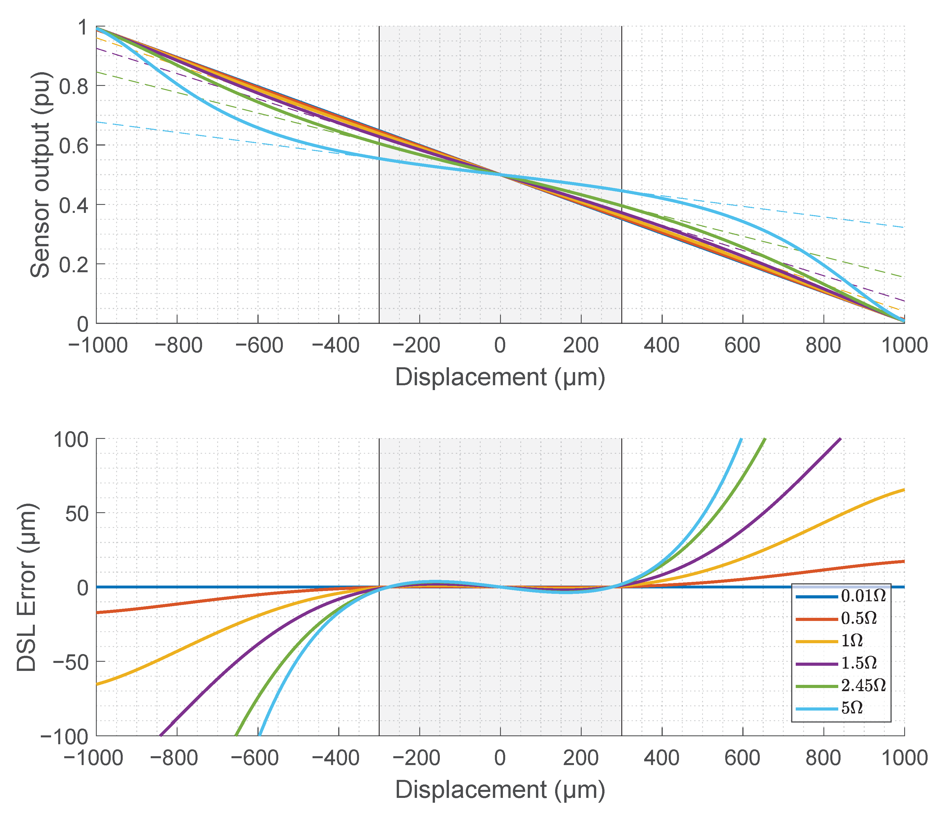
However, the simplified analysis is based on an assumption of ideal windings without any resistive losses in the windings. The analysis can be expanded by adding the series resistance
of the coil to the Equation (
1) expressed as:
The effect of stray resistance on the linearity of the sensor and measurement error is shown in
Figure 2. The resistance of the coils is assumed to be equal.
2.3. Electromagnetic Design
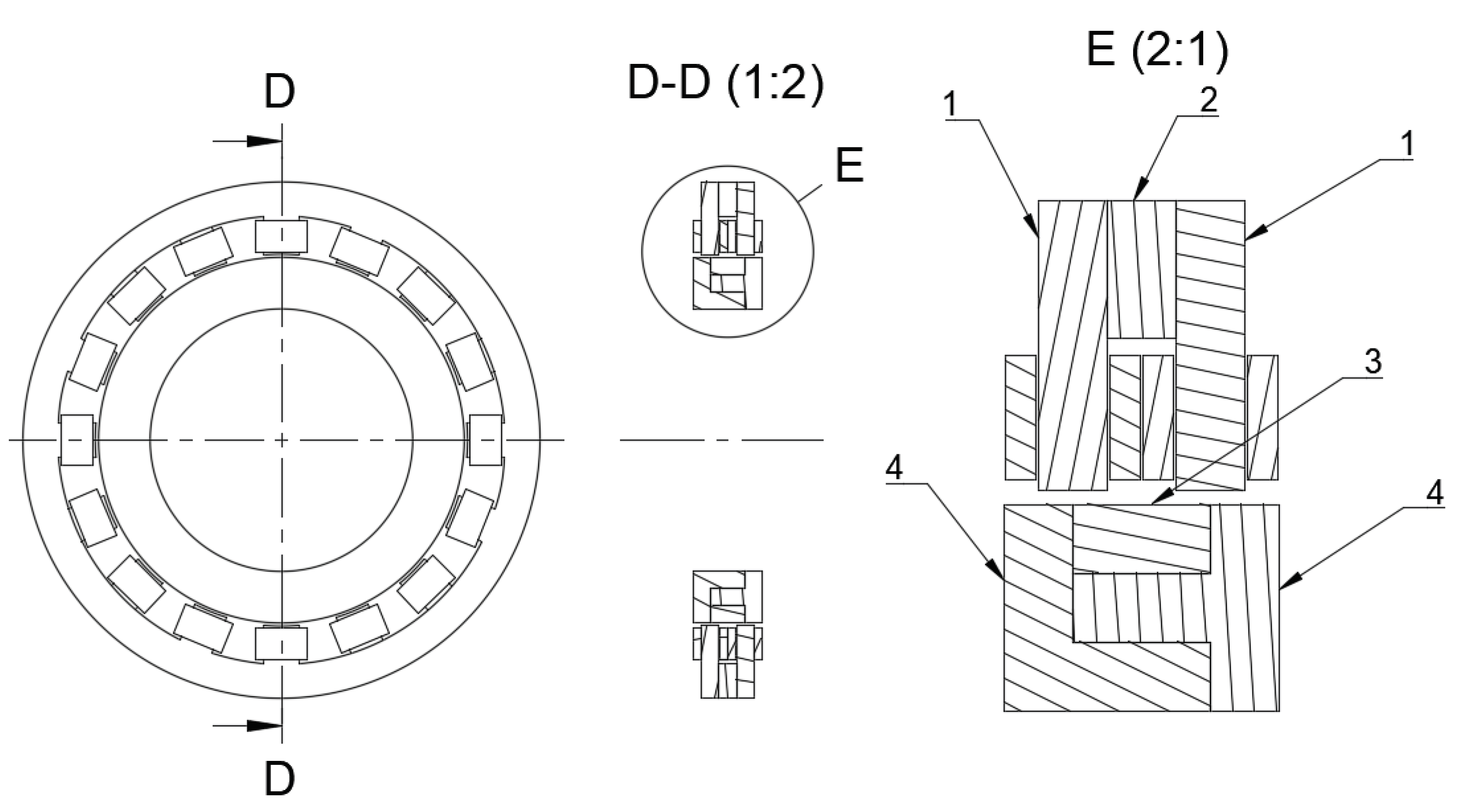
The main dimensions of the sensor, presented in
Figure 3, are defined by the dimensions of the electrical machine. The rotor diameter defines the minimum inner diameter, and the outer diameter is defined by the usable radial space inside the machine frame structure. Axial length was chosen based on the space requirement of the sensor winding such that the sensor is still easily manufacturable. Air gap length depends on the actual mechanical clearance of the rotor system. An additional safety margin was added, to account for manufacturing tolerances and to allow full rotor movement along the mechanical safety bearings without any risk of touching the sensor mechanically.
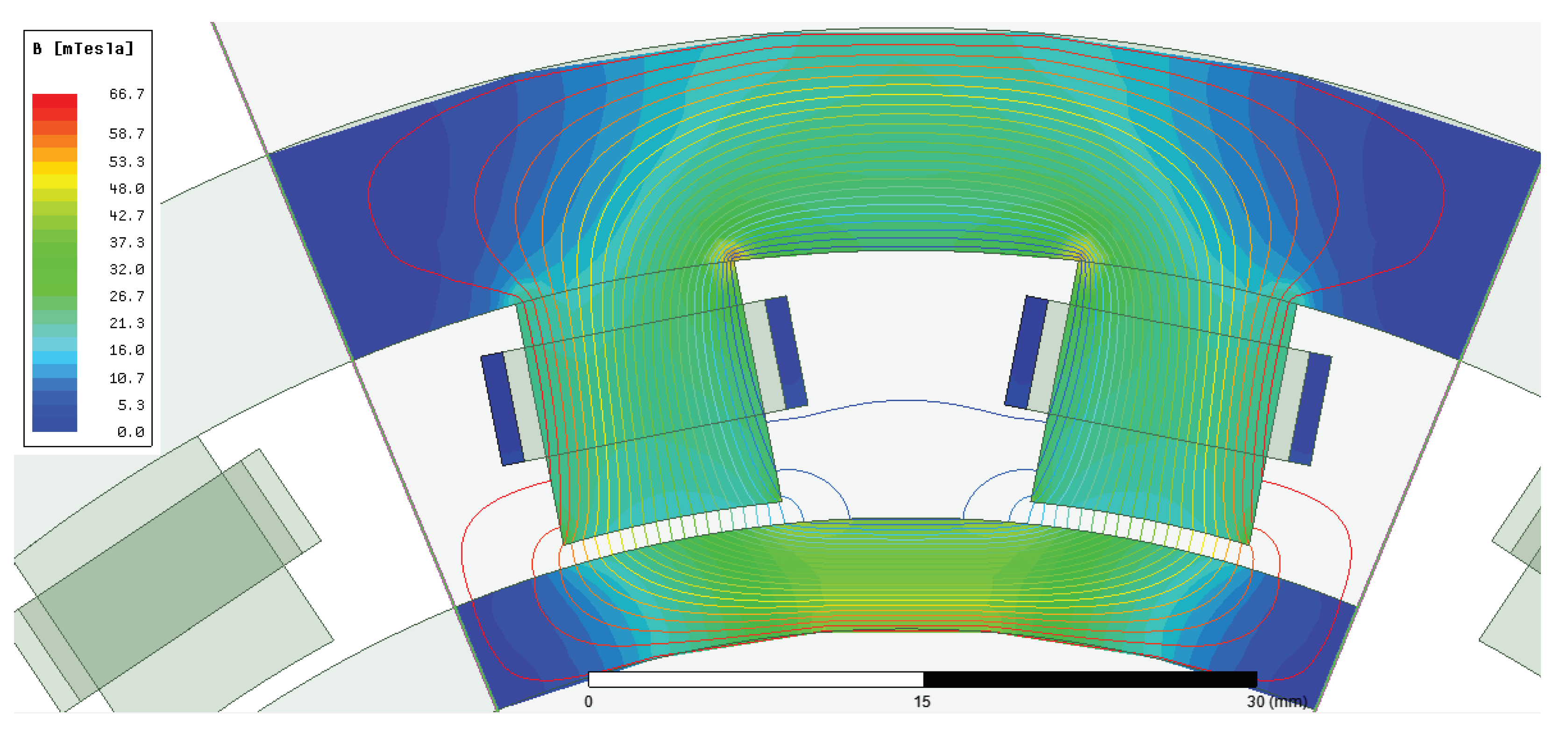
Lamination stack material selection was carried out so as to choose a material with low eddy current and hysteresis losses considering the 10 kHz excitation frequency and the material chosen was a compromise between electromagnetic properties and use of material common throughout the electrical machine manufacturing industry. The magnetic flux density was designed to utilize only a small portion of the linear region of the BH curve and flux density was restricted by the power handling capability of the excitation amplifier. The winding turn number should be adjusted to fit the properties of the exciting power amplifier’s voltage level and current driving capability. Electromagnetic design parameters are given in
Table 2 and the design FEM analysis in
Figure 4.
The axial measurement is achieved using the same stator stack geometry as for radial direction measurement, but all the four pole pairs of the stack are connected in series, as illustrated in the connection diagram in the
Figure 3. All the four pole pairs of the stator stack are used to reject the sensitivity of the axial sensing circuit to the radial displacement change. The differential measurement for the axial direction is achieved by utilizing two sensor identical stacks in axial direction, defined as front and backrow in
Figure 3. The rotor piece width in the example sensor design is 10 mm, from which results that in the centered position the rotor piece will overlap with the axial tooth only by half of the tooth width. This overlapping on both halves of the axial sensor stack as illustrated in
Figure 5 allows the self-inductance of the front and back row sensing pole pairs change differentially when the rotor position changes in the axial direction.
2.4. Phase Sensitive Signal Processing
Displacement sensor operation is based on measuring the voltage signal output from all three axes. The measurement coils are driven by the same amplified excitation signal common to all the axes. The output of the sensor is an alternating current signal at the frequency of the excitation signal, which needs to be demodulated to obtain a signal corresponding to the static mechanical displacement.
The demodulation can be achieved using simple amplitude-based demodulation techniques such as a peak detector or root-mean-square (rms) detector circuit, or by rectifying and filtering the output signal. The drawback of these demodulation methods is that they can only observe the magnitude change of the measured signal, and phase information is lost. By synchronizing the excitation signal generation and measurement, it is possible to use phase-sensitive detection methods. Use of a synchronous demodulation scheme using in-phase and quadrature signals preserve amplitude and phase information without losing information from the measurement signal. Preserving the phase information allows delay and phase shift in the system to be taken into account and compensated during the signal processing. Synchronous demodulation acting as a narrow bandpass filter at the excitation frequency helps to achieve a high dynamic range even if off-band or spurious noise is present in the measurement system [
25]. These properties of phase-sensitive demodulation schemes allow a low-noise high-bandwidth measurement signal to be obtained in magnetic bearing control systems, where the displacement sensor typically needs to be positioned next to a pulse-width modulated magnetic bearing power circuit coupling, which introduces noise into the sensor circuit.
Excitation signal generation and synchronous demodulation with a phase lock can be constructed using a fully digital principle with the addition of A/D- and D/A-converters. In a magnetic bearing application, a shared digital signal processing system can be utilized with the closed-loop position control. The fully digital signal processing principle is presented in
Figure 1. The sine wave excitation signal is generated in the digital domain and fed through a digital-to-analog converter to the analog power amplifier. The measurement bridge output voltages from all three axes are brought back to the digital domain through an analog-to-digital converter. The amplified excitation signal is also measured back to the digital domain to achieve ratio-metric measurement that compensates possible gain and phase drift in the analog measurement circuit. The excitation signal
is digitally generated with 0° and 90° phase shifts and can be expressed in a complex plane as
where
corresponds the angular frequency of the excitation signal. Similarly the measurement signal
can be defined in the complex plane as:
where
r corresponds to the measurement signal amplitude and
phase shift. Mixing the measurement signal with the generated local oscillator excitation signal down-converts the measurement signal in the frequency domain to the dc level but also generates double the excitation frequency component defined in the complex plane as:
The double frequency () signal can be low-pass filtered or averaged (integrated) over the period. The resulting filtered signal corresponds to demodulated in-phase and quadrature signals of the displacement measurement. The dynamic bandwidth of the measured displacement signal can be defined and limited by a digital domain low-pass filter located after the mixing process.
After the demodulation process, two complex form values for both the measurement signal and the excitation signal are obtained. Dividing the measurement signal by the excitation signal in a complex plane gives a ratiometric result whose phase is aligned to the phase of the measured excitation signal. The operation principle compensates for the effect of the total signal chain delay from the excitation output to the measurement input. Thus, the ratiometric measurement result can be declared as the real part of the complex value, with the imaginary part being insignificantly small.
3. Experimental Results
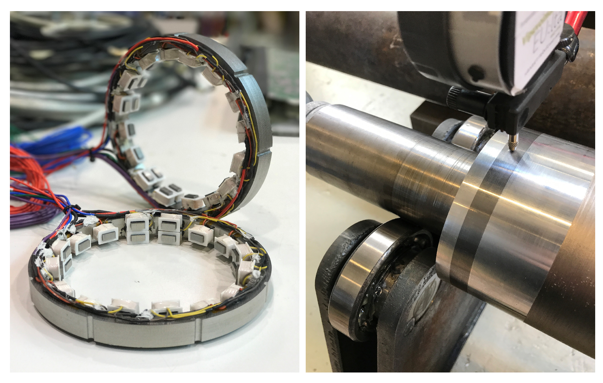
The designed sensor was manufactured to be able to verify the sensor design and its operational performance in a real industrial application. The wound sensor stator stack and laminated piece on the rotor shaft of the electrical machine are presented in
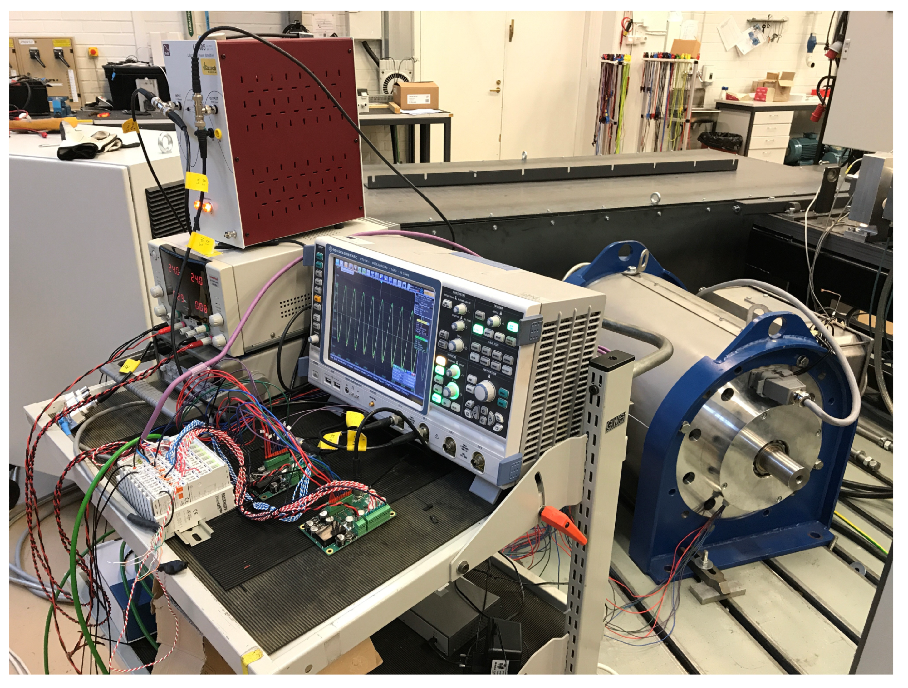
Figure 6. The sensor was calibrated on a table test rig utilizing a linear XYZ-axis microscrew stage. After calibration, the sensor was installed in a 350 kW, 15,000 r/min industrial solid-rotor induction motor. Two sensors were installed and functioned as part of the magnetic bearing control feedback loop, while providing radial and axial displacement measurements of the machine’s rotor from both ends of the machine. The laboratory test setup, including the high-speed induction machine, is shown in
Figure 7.
The motor was driven by an ABB ACS800 industrial variable frequency drive. In the practical tests, the rotational speed was limited to 1200 r/min for safety reasons. Magnetic bearing position control and sensor signal digital processing were implemented in a Beckhoff TwinCAT real-time environment utilizing a Beckhoff Industrial PC, EtherCAT connected power sources driving the magnetic bearing coils and Beckhoff analog I/O terminals handling the interface to the analog circuitry and sensor coils.
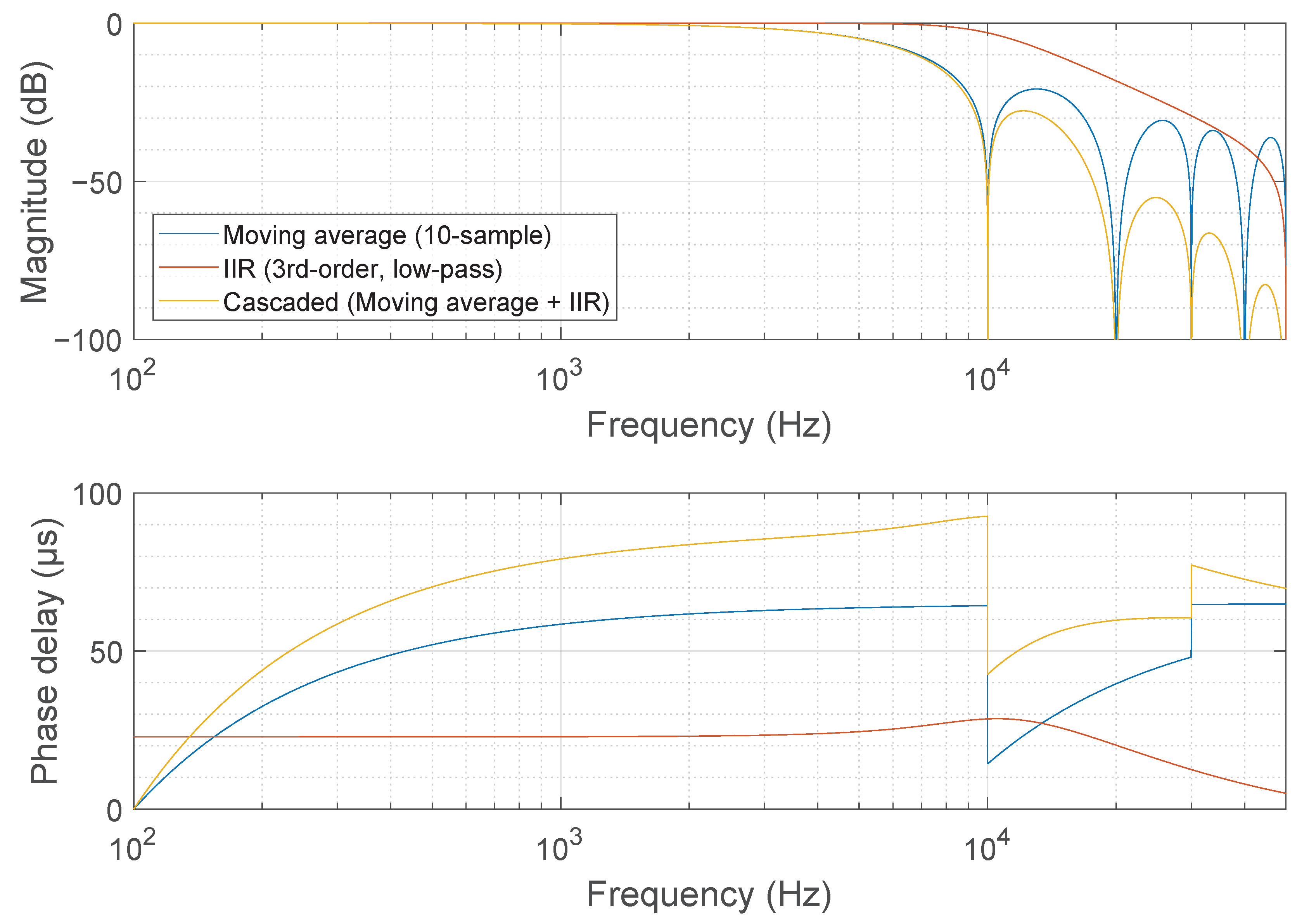
A digitally generated 10 kHz sine wave excitation signal was driven through the Beckhoff EL4732 ±10 V, 16-bit, 100,000 samples per second analog output terminal acting as a digital-to-analog converter. The N4L LPA05A laboratory power amplifier amplified the excitation signal to 10.7 Vrms driving all the parallel-connected measurement coils. The excitation signal and measurement signals were converted back to the digital domain through instrumentation amplifiers and by utilizing the Beckhoff EL3702 ±10 V, 16-bit, 100,000 samples per second EtherCAT analog input terminal as an analog-to-digital converter. The demodulation, filtering and ratiometric signal processing of the digital measurement signals were implemented in the Beckhoff TwinCAT environment. The dynamic properties of the displacement measurement were determined by the dynamics of the low-pass filtering after the frequency mixer. The low-pass filter gain and phase frequency response are presented in
Figure 8.
3.1. Static Accuracy and Linearity
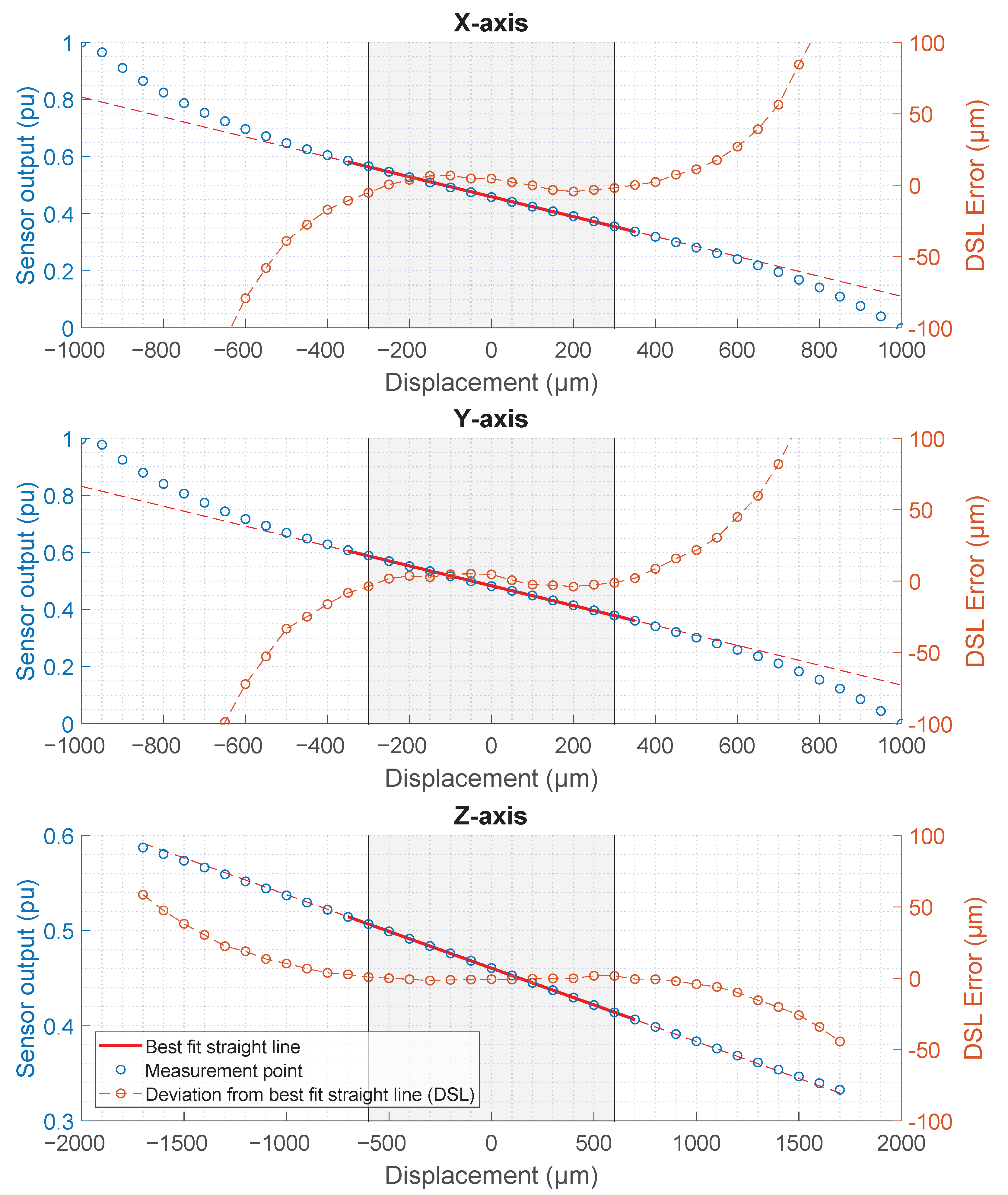
The sensor was calibrated and measured against the OptoSigma precision XYZ axis linear stage with manual micrometer screws. A first-order linear fit was used with the measured points over the specified measurement range of ±300 µm radial and ±600 um axial axes. After the linear fit, measurement point deviation from the fitted straight line was calculated. The static measurement results after calibration from all three axes are presented in
Figure 9. Note that the static cross-coupling effects between the three axes were noticed not to be separable from the mechanical inaccuracy of the test setup, including linear stage and rotor piece machining inaccuracies. Measurable cross-coupling between axial and radial axes over the measurement range was less than 2
. Deviation from straight-line fit was smaller than
in the specified
measurement range for the radial direction. Deviation from the straight-line fit was smaller than
in the specified
measurement range for the axial direction. The better linearity of the axial direction is a result of a longer total mechanical range with respect to the size of the measurement range compared to the radial axes. The maximum measurement range for radial direction is
and for axial direction
. Experimentally measured non-linearity values were significantly less than the
requirement specified for non-linearity in
Section 2.
3.2. Dynamic Performance
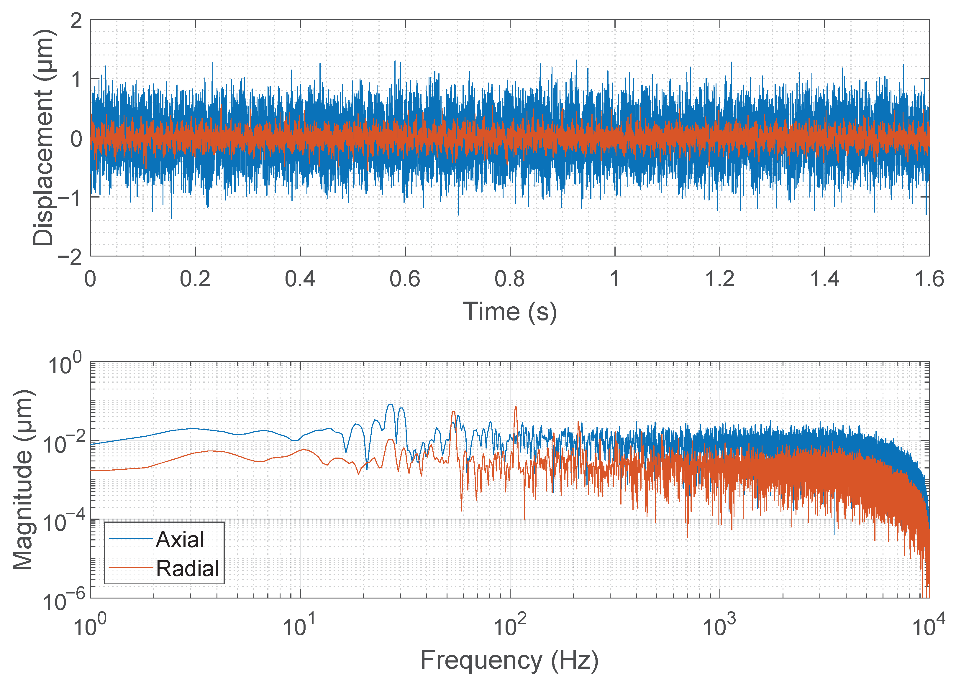
Sensor performance was tested while the sensor was part of the feedback loop of the active magnetic bearing control system. First, the noise level was measured at standstill with the rotor lying on the safety bearings. Noise level measurement from the radial and axial axes is presented in
Figure 10. Noise of 0.11
rms was found in the radial axes and 0.35
in the axial axis. These values correspond to 0.7
and 2.1
peak-to-peak noise, respectively. The noise levels scaled relative to maximum measurement range of
for radial and
for axial direction results as −76 dB for radial direction and −74 dB for axial direction measurement. From the frequency domain analysis, it was seen that the noise is evenly distributed over the measurement bandwidth and no narrowband noise peaks are visible.
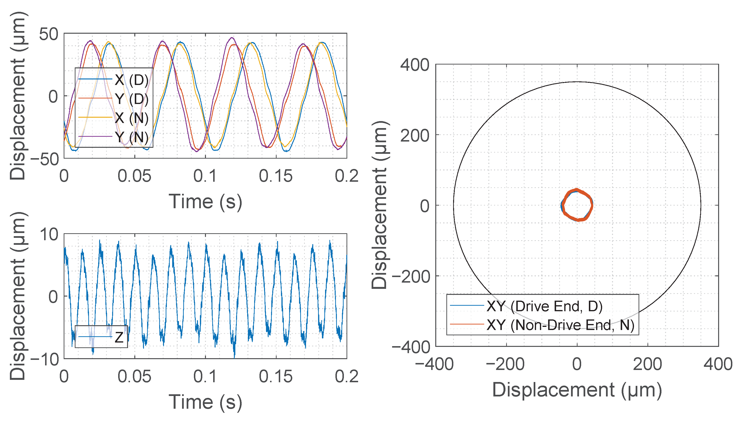
After noise measurement, and to verify proper operation in a noisy industrial environment, the dynamic performance was tested while the rotor was rotating at a moderate velocity of 1200 r/min and levitated by the active magnetic bearing control. It should be noted that the controller used in the experimental tests included additional control functions. Two types of measured displacement signals were recorded while levitating and rotating the machine. The higher amplitude signal visible in
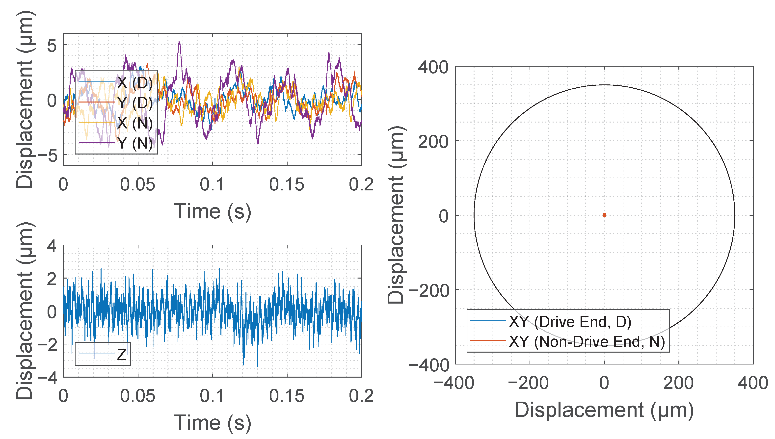
Figure 11 presents the actually measured rotor displacement by the sensor after the demodulation and low-pass filtering. The lower amplitude signal in
Figure 12 presents the signal driven to the magnetic bearing control input with additional signal processing [
26]. The harmonic content corresponds mainly to unbalance, runout and other mechanical non-idealities present in the system, and the harmonics generate unnecessary control action if not removed from the controller input. The first, second, third, fourth and fifth harmonics of the rotational frequency were removed from the radial position controller input signal, and correspondingly the first, second and fourth harmonics were removed from the axial controller input.


 ,
, 


