Article

Modeling and Analysis in Trajectory Tracking Control for Wheeled Mobile Robots with Wheel Skidding and Slipping: Disturbance Rejection Perspective

1
School of Automation Science and Electrical Engineering, Beihang University, Beijing 100191, China
2
Science and Technology on Aircraft Control Laboratory, Beihang University, Beijing 100191, China
3
Ningbo Institute of Technology, Beihang University, Ningbo 315800, China
4
Department of Electrical and Electronic Engineering, University of Nottingham, Nottingham NG7 2RD, UK
*
Author to whom correspondence should be addressed.
Submission received: 3 July 2021 / Revised: 10 August 2021 / Accepted: 24 August 2021 / Published: 4 September 2021
(This article belongs to the Section Actuators for Land Transport)

Abstract

:
Wheeled mobile robot (WMR) is usually applicable for executing an operational task around complicated environment; skidding and slipping phenomena unavoidably appear during the motion, which thus can compromise the accomplishment of the task. This paper investigates the trajectory tracking control problem of WMRs via disturbance rejection in the presence of wheel skidding and slipping phenomena. The kinematic and dynamic models with the perturbed nonholonomic constraints are established. The trajectory tracking control scheme at the dynamic level is designed so that the mobile robot system can track the virtual velocity asymptotically, and counteract the perturbation caused by the unknown skidding and slipping of wheels. Both simulation and experimental works are conducted, and the results prove the performance of the proposed control scheme is effective in terms of tracking precision and disturbance attenuation.

1. Introduction

Wheeled mobile robots (WMRs) have wide applications in space exploration, manufacturing, services, etc. [1,2,3,4]. High performance motion control of WMR is the prerequisite for completing various tasks efficiently. So far, most studies involving the tracking control methods of WMR generally assume that mobile robots are based on nonskidding and nonslipping, which are nonholonomic constraints. Typical examples are backstepping-based control schemes in [5,6], sliding mode algorithms in [7,8,9], neural network methods in [10,11,12], and robust control in [13,14]. Unfortunately, the ignorance of slipping and skidding is apparently not consistent with most implementations, especially in an unstructured, complicated environment, such as wet, forestry, icy road, or rapid turning, which unavoidably compromises the accomplishment of tasks.
The wheel skidding effect causes lateral velocity perturbation, while the slipping effect causes forward velocity perturbation of the right and left driving wheels [15]. To tackle this problem, different approaches have been proposed by researchers. A conditional global positioning system (GPS)-based path following controller was proposed in [15] for four generic WMRs considering wheel skidding and slipping. The proposed controller utilized real-time kinematic-GPS and other aiding sensors to determine the robot’s pose and achieved the path following performance. Similarly, the tracking control scheme based on GPS was developed for typical car-like WMR by using a kinematic model to address the skidding and slipping effect in [16]. Dixon et al. [17] introduced the robust tracking and regulation controller by establishing the system kinematics with wheel skidding, based on the previous research in [18]. Gonzalez et al. [19] designed the adaptive controller in kinematics model under slipping conditions by using linear matrix inequalities. An adaptive tracking control method considering the sliding effect was presented and a sliding model observer was utilized for the robot system to estimate the sliding parameters in [20]. These motion controllers are mainly based on kinematics. The motion performance may be compromised when there is disturbance, nonlinearities and uncertainties in WMR.
Thus, the tracking control approach considering system dynamics becomes one important topic. The neural-network-based control solutions worked well for solving the skidding and slipping problem. For example, an improved adaptive controller in [21] was developed to track the desired trajectory. In this control scheme, the system states of the studied WMR were applied to a neural-network-based online weight-tuning scheme so that system convergence was ultimately established. The scheme only considered the longitudinal slipping. In [22], the reinforcement-learning-based adaptive neural scheme for WMR was designed in the implementation of path tracking, and the existence of skidding and slipping effects was estimated via the action network. This tracking control algorithm depended on the online learning time. A nonlinear trajectory tracking control scheme was proposed that uses a nonlinear function in terms of flexibility, slipping and skidding variations [23]. The disturbance observer-based method is another alternative to tackle this problem. An adaptive tracking control method was proposed in [24] for WMR, taking into account the skidding and slipping. The disturbance observer was designed to estimate the total disturbances, and the adaptive controller was designed to guarantee that the tracking errors asymptotically converge to zero. An adaptive nonlinear feedback control scheme that compensated for the longitudinal slipping was presented in [25] to realize the trajectory tracking of the tracked mobile robots. The observer for the orientation angle was developed to estimate the immeasurable orientation angle of the tracked mobile robot through utilizing the coordinate values. In [26], an improved linear active disturbance rejection control scheme was proposed for trajectory tracking control of a six-wheeled corner steering rover. The tracking differentiator and nonlinear state error feedback were introduced, and the input disturbance attenuation was achieved. In [27], a disturbance observer was designed, and then the virtual velocity control approach together with the robust trajectory tracking control was presented based on the observer. The robust tracking controllers were developed for WMRs, incorporating with the generalized extended state observer in [28] and fuzzy disturbance observer in [29] to attenuate disturbance with the consideration of the existing skidding and slipping. The trajectory tracking results in [28,29] were not as desirable as expected for the circle trajectory. In general, the existence of wheel’s skidding and slipping effects destroys the nonholonomic constraints, and it makes the kinematics and dynamics model have more complex disturbance and thus, makes the control design procedure more difficult. As a consequence, to enhance the antidisturbance ability and achieve satisfactory tracking performance of the robot system, it is necessary to further explore the robust tracking control approach based on the disturbance observer for WMRs, considering the wheel skidding and slipping, and disturbance.
In this paper, to achieve the trajectory tracking, considering the wheel skidding and slipping, under the kinematic perturbations, the virtual velocity control law at the kinematic level is first used to converge the pose error to zero. Then, the tracking control scheme is developed by considering the tracking performance and via the disturbance observer to counteract the disturbance lead by the unknown skidding and slipping, together with the model uncertainties, and unknown bounded disturbances. Consequently, the stability and performance of the designed controller is guaranteed.
This remainder of this study is structured as below. Section 2 details the methods, such as the system modeling with wheel skidding and slipping, the tracking problem for the nonholonomic WMR, and the robust tracking controller via disturbance rejection. The results are given in Section 3 to validate the tracking control scheme, including the simulation and experiment works. Finally, Section 4 gives conclusions.

2. Methods

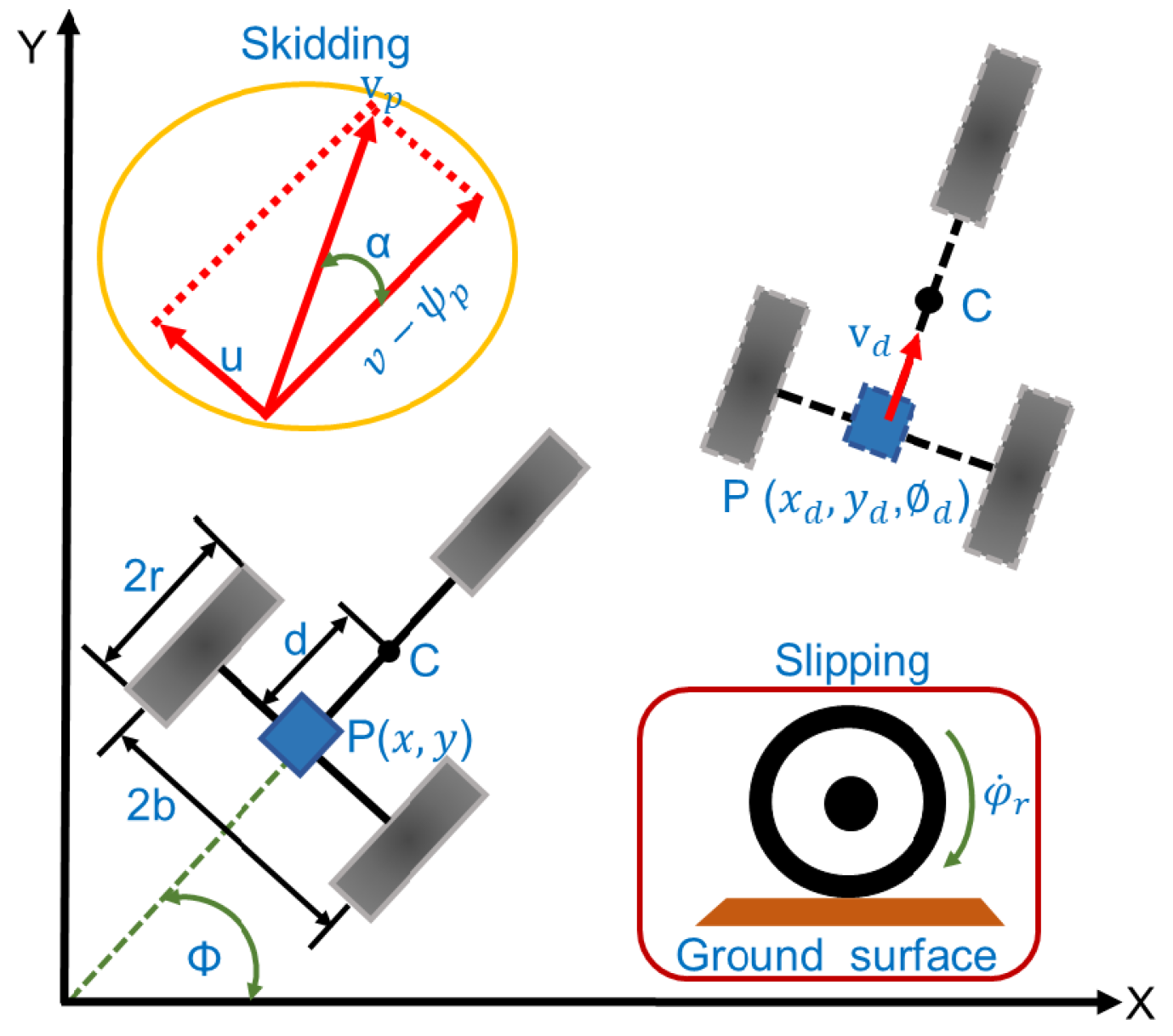
2.1. System Modeling

As a representative application of nonholonomic systems, the WMR platform under study is illustrated in Figure 1. The platform is equipped with two driving wheels installed on one shaft, together with a following wheel that can move in any direction and support the robot platform. Both left and right driving wheels are actuated via two direct drive motors independently, and both driving motors share the same properties, for example, position, velocity, force response, etc.
The dynamic modeling of WMR in the Lagrange form [27,28,29] is established as follows:
M q q ¨ + V q , q ˙ q ˙ + G q + τ d = B q τ A T q λ
where q = x y ϕ θ r θ l T 5 × 1 is the generalized coordinates, x, y are the position variables in the inertial coordinate system, ϕ is the forward direction angle, θ r , θ l are the angular position for the right and left wheel, M q 5 × 5 is a symmetric, positive definite inertia matrix, V q , q ˙ 5 × 5 is the centripetal and Coriolis matrix, G q 5 × 1 is the gravity vector, τ d 5 × 1 denotes the bounded external disturbances, B q 5 × 2 is the input transformation matrix, τ is the input torque provided by the motors, A q 3 × 5 is the matrix associated with the constraints, and λ is the vector of constraint forces.
Because the centroid C is not coincided with geometric center P, the following constraint is available with wheel pure rolling:
x ˙ sin ϕ + y ˙ cos ϕ d ϕ ˙ = 0 x ˙ cos ϕ + y ˙ sin ϕ + b ϕ ˙ = r θ ˙ r x ˙ cos ϕ + y ˙ sin ϕ b ϕ ˙ = r θ ˙ l
where x ˙ and y ˙ are the velocity description of the WMR, d describes the distance between the centroid and geometric center of the two driving wheels, θ ˙ r and θ ˙ l are the angular velocities, b is the half width of the robot, and r is the wheel radius. For convenient calculation, Equation (2) is denoted as follows:
A q q ˙ = 0
where A q = sin ϕ cos ϕ d 0 0 cos ϕ sin ϕ b r 0 cos ϕ sin ϕ b 0 r is the nonholonomic constraint matrix. In addition, J q = cos ϕ sin ϕ 0 1 r 1 r d sin ϕ d cos ϕ 1 b r b r T is in the null space of A q and satisfies the condition A q J q = 0 , facilitating the following representation of the kinematics of WMR in the presence of unknown skidding and slipping.
However, these constraints are not always satisfied because wheel skidding and slipping destroys the pure rolling. Hence, considering the perturbed nonholonomic constraints caused by the wheel skidding and slipping effects, the motion equation of the WMR is given as follows:
x ˙ sin ϕ + y ˙ cos ϕ d ϕ ˙ = u x ˙ cos ϕ + y ˙ sin ϕ + b ϕ ˙ = r θ ˙ r φ r x ˙ cos ϕ + y ˙ sin ϕ b ϕ ˙ = r θ ˙ l φ l
where u is the lateral skidding velocity of WMR, φ r and φ l are the perturbed angular velocities of the two driving wheels caused by slipping respectively. Equation (4) can be stated in matrix form as follows:
A q q ˙ = u r φ r r φ l T
Considering unknown skidding and slipping, the kinematics model of WMR is expressed as follows:
q ˙ = J q ξ ψ + P q c 0
where ξ = v ω T , ψ = ψ v ψ ω T . v = r θ ˙ r + θ ˙ l 2 is the forward linear velocity, ω = r θ ˙ r θ ˙ l 2 b is the angular velocity, ψ v = r φ r + φ l 2 denotes the longitudinal slipping velocity, and ψ ω = r φ r φ l 2 b is the perturbed angular velocity. P q c 0 represents the unmatched disturbance because of the perturbed nonholonomic constraints, specifically the following:
P q = sin ϕ cos ϕ 0 0 0 0 0 0 1 0 0 0 0 0 1 T , c 0 = u φ r φ l T .
Assumption 1.
The perturbations ψ v , ψ ω and u are bounded with ψ v δ 1 , ψ ω δ 2 and u δ 3 , also their first, second, third derivatives are bounded, where δ i , i = 1 , 2 , 3 are positive constants. The perturbations ψ v , ψ ω , u and both the derivatives are small relative to the reference velocity.
The derivation of perturbed generalized constraint is as follows:
q ¨ = J ˙ q ξ ψ + J q ξ ˙ ψ ˙ + P ˙ q c 0 + P q c ˙ 0
Substituting Equation (7) into Equation (1), and combining with A q J q = 0 , the dynamic model with skidding and slipping is derived as follows:
M 1 q ξ ˙ ψ ˙ + V 1 q , q ˙ ξ ψ + C 1 q c ˙ 0 + C 2 q c 0 + C 3 q + τ d = τ
where
M 1 q = J T q B q 1 J T q M q J q V 1 q , q ˙ = J T q B q 1 J T q M q J ˙ q + V q , q ˙ J q C 1 q = J T q B q 1 J T q M q P q C 2 q = J T q B q 1 J T M q P ˙ q + V q , q ˙ P q C 3 q = J T q B q 1 J T q G q
As the WMR studied operates on a ground without any slope, we obtain that gravity vector G q equals matrix zero and thus, the matrix C 3 q also equals zero. Equation (8) is simplified to the following:
ξ ˙ = V 2 q , q ˙ ξ + M 2 q τ V 2 q , q ˙ ψ + ψ ˙ M 2 q C 1 q c ˙ 0 + C 2 q c 0 M 2 q τ d
where M 2 q = M 1 1 q , V 2 q , q ˙ = M 1 1 q V 1 q , q ˙ . As M 2 q , V 2 q , q ˙ is determined by q that, in turn, is affected by skidding and slipping, the parameter uncertainty and variation should be considered. Then, Equation (9) is specified as follows:
ξ ˙ = V 2 q , q ˙ ξ + M 2 q τ V 2 q , q ˙ ψ + ψ ˙ M 2 q C 1 q c ˙ 0 + C 2 q c 0 M 2 q τ d + Δ V 2 q , q ˙ ξ + Δ M 2 q τ
where Δ V 2 q , q ˙ , Δ M 2 q are parameter uncertainties and variation caused by skidding and slipping. Define D = V 2 q , q ˙ ψ + ψ ˙ M 2 q C 1 q c ˙ 0 + C 2 q c 0 M 2 q τ d + Δ V 2 q , q ˙ ξ + Δ M 2 q τ . Therefore, the following holds:
ξ ˙ = V 2 q , q ˙ ξ + M 2 q τ + D
where the disturbance D denotes the compound disturbance coming from wheel skidding and slipping, input disturbance, parameter variation, and parameter uncertainty, such as mass, moment of inertia, etc.
Assumption 2.
The disturbance D satisfies the condition D α and D ˙ β , where α and β are positive constant.

2.2. Tracking Problem for Nonholonomic WMR

To design the tracking control scheme in presence of skidding and slipping, the pose of WMR is defined as q t = x y ϕ T , while the reference pose is defined as q d t = x d y d ϕ d T . The tracking error term q e t = x e y e ϕ e T is specified as follows:
q e = x e y e ϕ e = cos ϕ sin ϕ 0 sin ϕ cos ϕ 0 0 0 1 x d x y d y ϕ d ϕ
To achieve the tracking control, the smooth velocity control law ξ c = f c q e , ξ d can be designed satisfying lim t q e t = 0 for any initialization value. To calculate the derivative of q e , the following formula is given:
q ˙ e = v d cos ϕ e v + y e ϕ ˙ v d sin ϕ e x e ϕ ˙ ω d ϕ ˙
The auxiliary velocity is as follows [30]:
ξ c = v c ω c = v d cos ϕ e + k 1 x e ω d + k 2 v d y e + k 3 v d sin ϕ e
where k 1 , k 2 , k 3 are positive parameters to be designed. To implement the inputting torque designing and reference speed following, the auxiliary velocity tracking error is defined as follows:
e t = ξ c ξ = v c v ω c ω
The next step aims at designing an inputting torque τ = τ r τ l T according to lim t e t = 0 and lim t q e t = 0 .

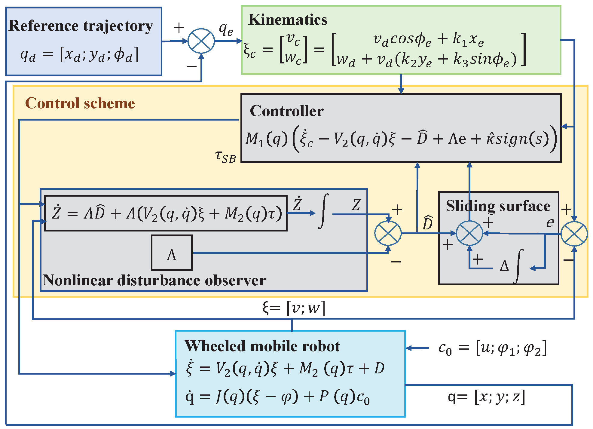
2.3. Control Design and Stability Analysis
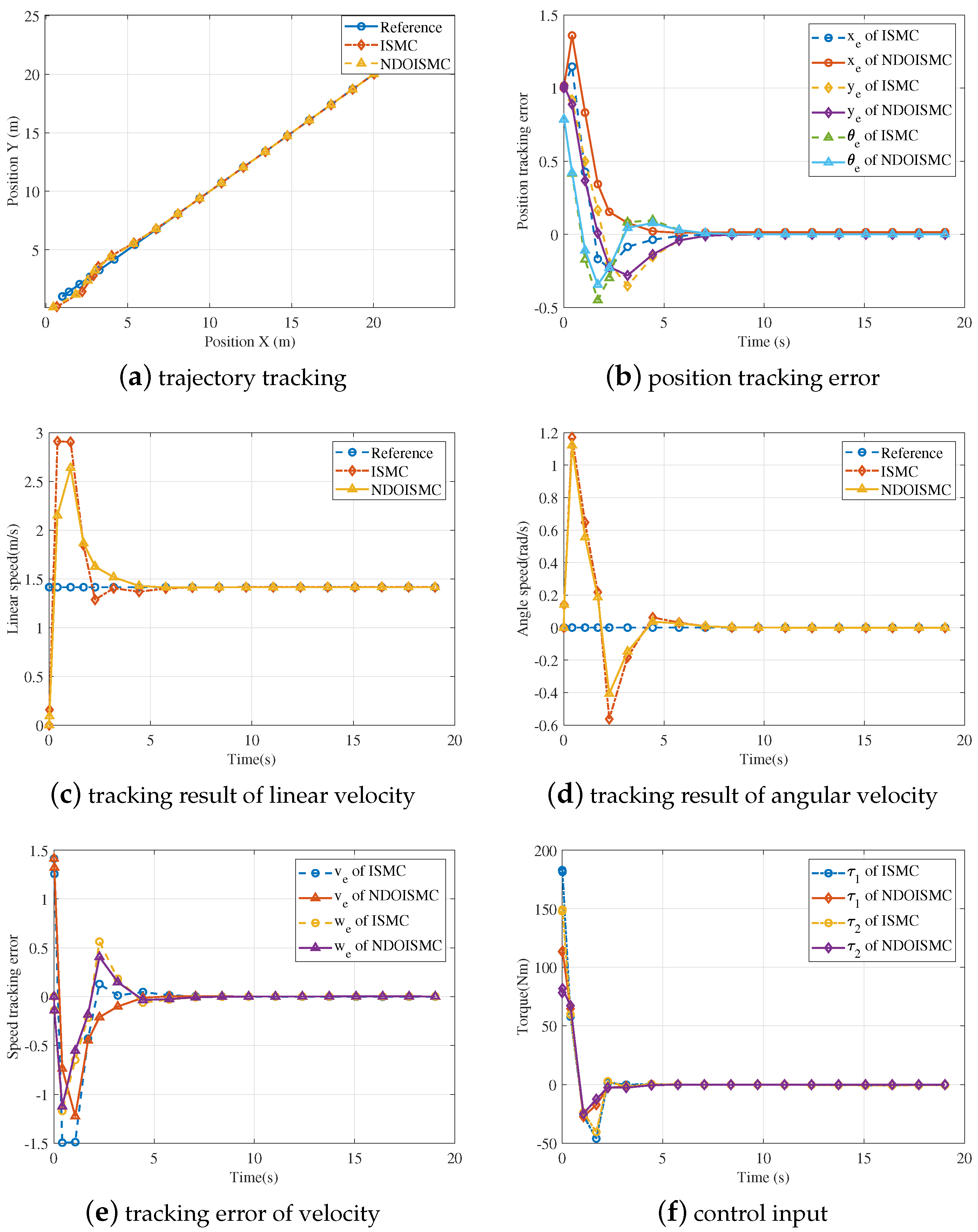
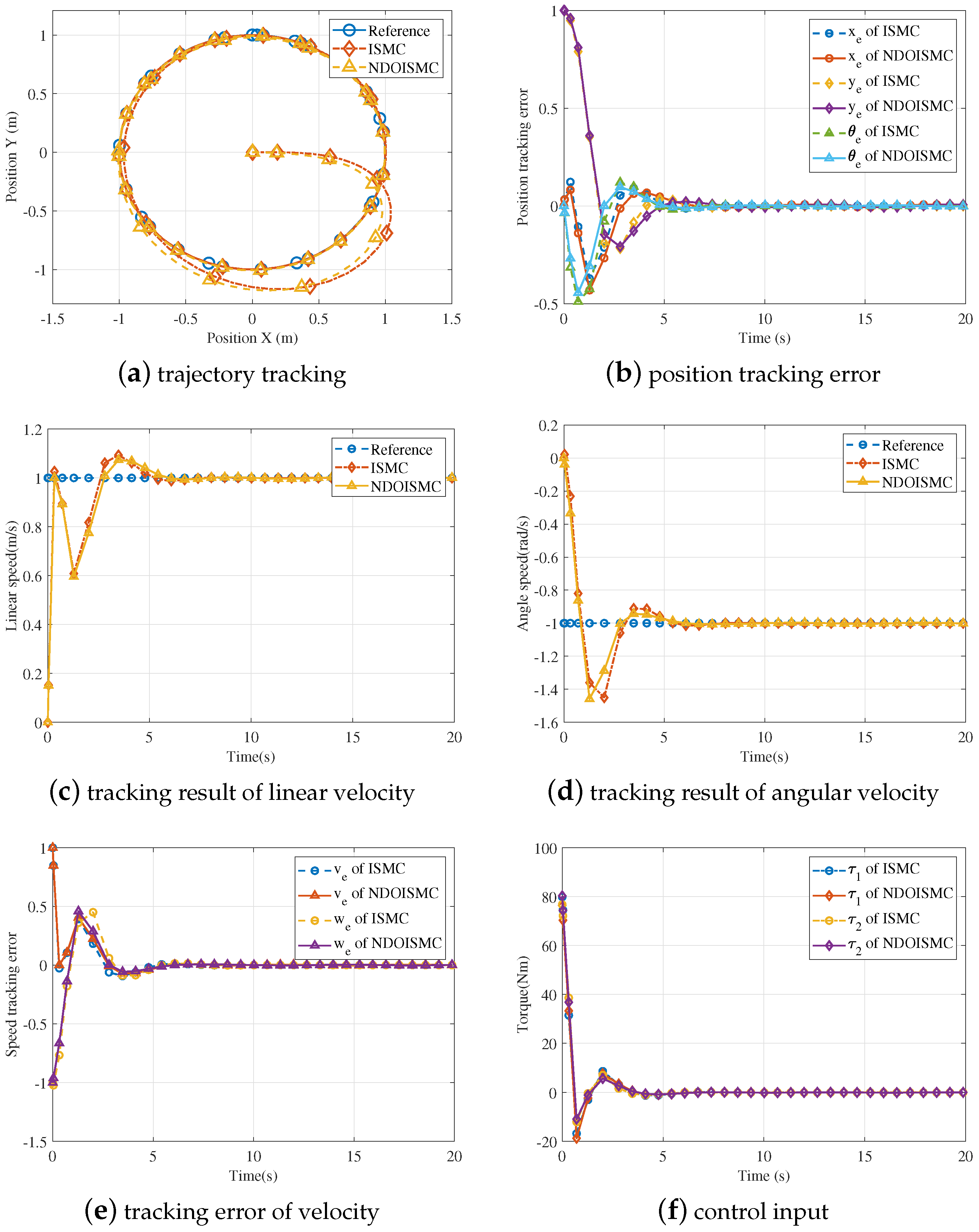
The nonlinear disturbance observer (NDO) is developed in the perturbed system to estimate the mismatched disturbance D. The NDO is given as follows:
Z ˙ = Λ D ^ + Λ V 2 q , q ˙ ξ + M 2 q τ D ^ = Z Λ ξ
where Z denotes the internal state of the nonlinear observer, D ^ is the estimation of the disturbance, Λ is the nonlinear part. The disturbance estimation error is as follows:
D ˜ = D D ^
Lemma 1
([16]). Assume that matix T R n * n is Hurwitz, and there exists a scalar > 0 satisfying e T t e λ max T 2 t .
The derivation of D ˜ is as follows:
D ˜ ˙ = D ˙ D ^ ˙ = D ˙ Z ˙ Λ ξ ˙ = D ˙ Λ D ^ + Λ ξ ˙ Λ D Λ ξ ˙ = D ˙ Λ D ^ Λ D = D ˙ + Λ D ˜
Thus, we have D ˜ = e Λ t D ( 0 ) + 0 t e Λ t s D ˙ ( s ) d s . In addition, we have the following:
D ˜ e Λ t D ( 0 ) + 0 t e Λ t s D ˙ ( s ) d s e Λ t D ( 0 ) + 0 t e Λ t s D ˙ ( s ) d s α e λ max Λ 2 t + β 2 λ max Λ e λ max Λ 2 t 1 α β 2 λ max Λ
To facilitate the result, γ = α β 2 λ max Λ is introduced and thus, D ˜ satisfies the condition D ˜ γ .
Remark 1.
The matrix Λ in Equation (18) should be chosen as the Hurwitz matrix, and λ max Λ is required to be sufficiently large.
For a better tracking effect, the integral sliding-mode controller (ISMC) is utilized to compensate the disturbance. Considering the disturbance estimation of Equation (16), the sliding-mode surface for WMR system is as follows:
s = e + Γ 0 t e t d τ + D ^
where D ^ is the disturbance estimation obtaining from NDO in Equation (16), Γ = ϖ 1 0 0 ϖ 2 is the integral constant of sliding surface. The ISMC scheme based on NDO is as follows:
τ = M 1 q ξ ˙ c V 2 q , q ˙ ξ D ^ + Γ e + κ sign s
where κ is the switching gain to be determined, and sign s = sign s 1 , sign s 2 T . Because α and β in Assumption 2 are unknown, the adaptive ISMC based on NDO (NDOISMC) is as follows:
τ = M 1 q ξ ˙ c V 2 q , q ˙ ξ D ^ + Γ e + κ ^ sign s
The adaptive law is as follows:
κ ^ ˙ t = κ ^ ˙ 1 0 0 κ ^ ˙ 2 = ρ 1 s 1 sign s 1 0 0 ρ 2 s 2 sign s 2
Substituting the control law Equations (22) and (23) into (20) yields the following:
s ˙ = e ˙ + Γ e + D ^ ˙ = ξ ˙ c ξ ˙ c D ^ + Γ e + κ ^ sign s + D + Γ e + D ^ ˙ = D ^ D κ ^ sign s + Λ D ^ D = I + Λ D ˜ κ ^ sign s
Defining κ ˜ t = κ t κ ^ t , the Lyapunov function is established as follows:
V 1 = 1 2 s T t s t + 1 ρ κ ˜ 2 t
The derivative of Equation (25) with respect to time is as follows:
V ˙ 1 = s T t s ˙ t + 1 ρ 1 κ ˜ 1 κ ˜ ˙ 1 + 1 ρ 2 κ ˜ 2 κ ˜ ˙ 2 κ ^ s s I + Λ γ s κ ˜ = s I + Λ γ s κ ^ + κ ˜ = s I + Λ γ + κ *
With the given condition of κ * I + Λ γ , the closed-loop system of WMR is bounded under the designed controller in Equation (26). Therefore, the defined sliding surface s t can be reached in finite time. As V 1 is non-incremental, s t and e t are bounded. The disturbance estimation error D ˜ and κ ˜ is also bounded. Thus the bounded D ˜ and κ ˜ can make the input τ bounded. Based on the Barbalat Lemma, the s t is asymptotically stable, i.e., lim t s t = 0 . Therefore, lim t q e = 0 is also asymptotically stable. The block diagram of the WMR system regarding wheel skidding and slipping from the disturbance rejection perspective is described in Figure 2.
Theorem 1.
For the mobile robot system in Equation (11) in the presence of wheel skidding and slipping, under the proposed control law in Equations (16) and (22) with the adaptive law in Equation (23), the tracking error of the mobile robot system is asymptotically stable under the developed robust tracking control scheme.

3. Results

3.1. Simulation Works

To evaluate the feasibility of the robust control scheme, the simulation is conducted for trajectory tracking. The software for the simulation is Matlab 2019b. The dynamic matrices are as follows:
M q = m 0 m d sin ϕ 0 0 0 m m d cos ϕ 0 0 m d sin ϕ m d cos ϕ I 0 0 0 0 0 I c 0 0 0 0 0 I c ,
V q , q ˙ = 0 0 m d ϕ ˙ cos ϕ 0 0 0 0 m d ϕ ˙ sin ϕ 0 0 0 0 0 0 0 0 0 0 0 0 0 0 0 0 0 , B q = cos ϕ sin ϕ sin ϕ cos ϕ 2 b 2 b r 0 0 r .
The parameters of the studied WMR system are listed in Table 1.
The control gains are Λ = 0.15 0 0 0.15 , κ = 2.5 0 0 2.5 , k 1 = 1 , k 2 = 1.5 , k 2 = 2.2 , the wheel skidding velocity is set as u = 0.3 e t , wheel slipping is chosen as θ r = 0.4 e 2 t , θ l = 0.2 e 2 t . Two different simulation modes, i.e., linear and circular path, are performed. For linear trajectory simulation, the desired path and velocity is x d = t , y d = t , v d = 2 m / s , w d = 0 rad / s , for circular trajectory is x d = sin t , y d = cos t , v d = 1 m / s , w d = 1 rad / s .
Figure 3 and Figure 4 show the simulation results of trajectory and velocity tracking for both linear and circular trajectory, considering skidding and slipping. In Figure 3a, the WMR moves from the starting position (0, 0) to gradually track the desired linear trajectory with starting position (1, 1). Figure 3b shows that the proposed control scheme can realize faster and higher-precision position tracking than the conventional ISMC scheme. Because the longitudinal slipping may directly decrease the linear velocity, the robust controller should properly adjust the linear velocity to compensate for the negative influence. For the same reason, the lateral skidding may directly influence the forward direction, so the proposed controller should adjust the forward direction to guarantee trajectory tracking. It can be clearly observed from Figure 3c,d that the proposed controller possesses better tracking ability and disturbance attenuation than the ISMC method. Figure 3e shows the linear and angular velocity tracking error, which indicates that the tracking error of NDOISMC is significantly smaller relative to the ISMC. The input torque for both driving wheels is adjusted by the controller to compensate for the disturbance. The input torque of the proposed controller is smaller than that of ISMC in Figure 3f, and thus, indicates that the proposed controller has better capability of disturbance attenuation. The proposed controller helps to alleviate the chattering effect greatly. In addition, the circular trajectory tracking effect is obtained, as shown in Figure 4 based on the proposed controller. Therefore, the proposed controller helps to improve the tracking precision, capability of disturbance attenuation and chattering alleviation, compared with conventional ISMC.

3.2. Experiment Works

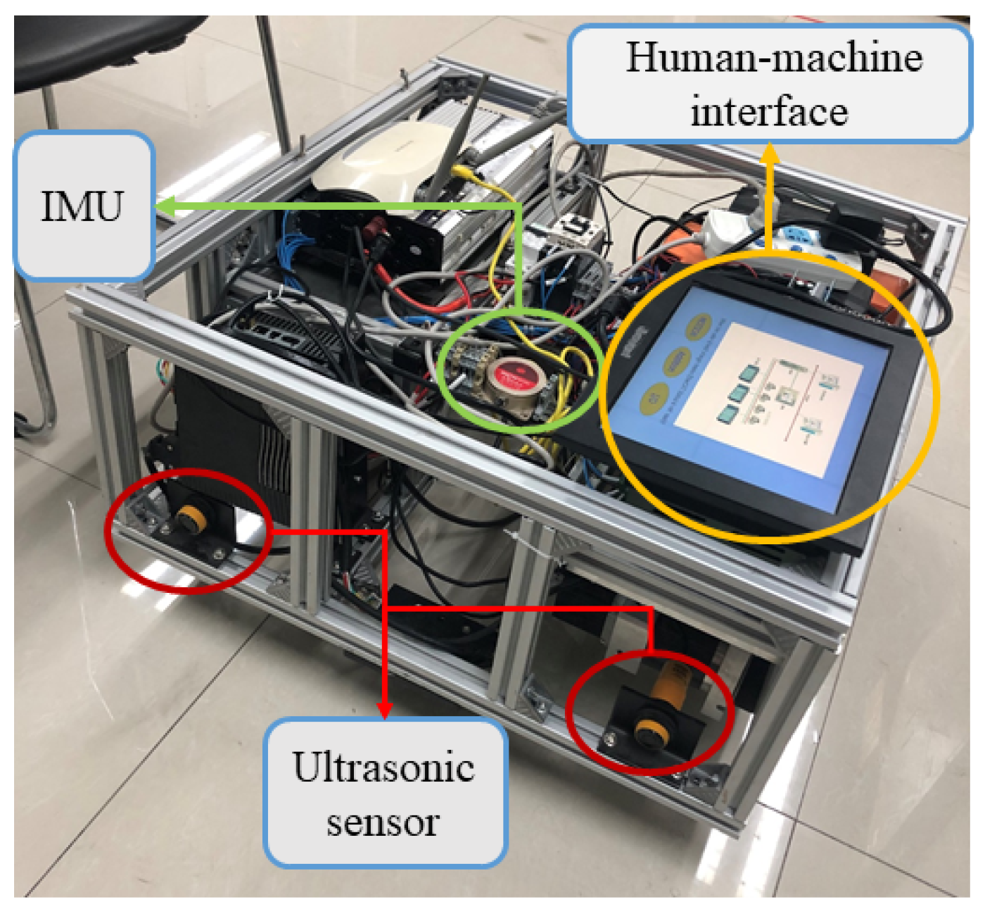
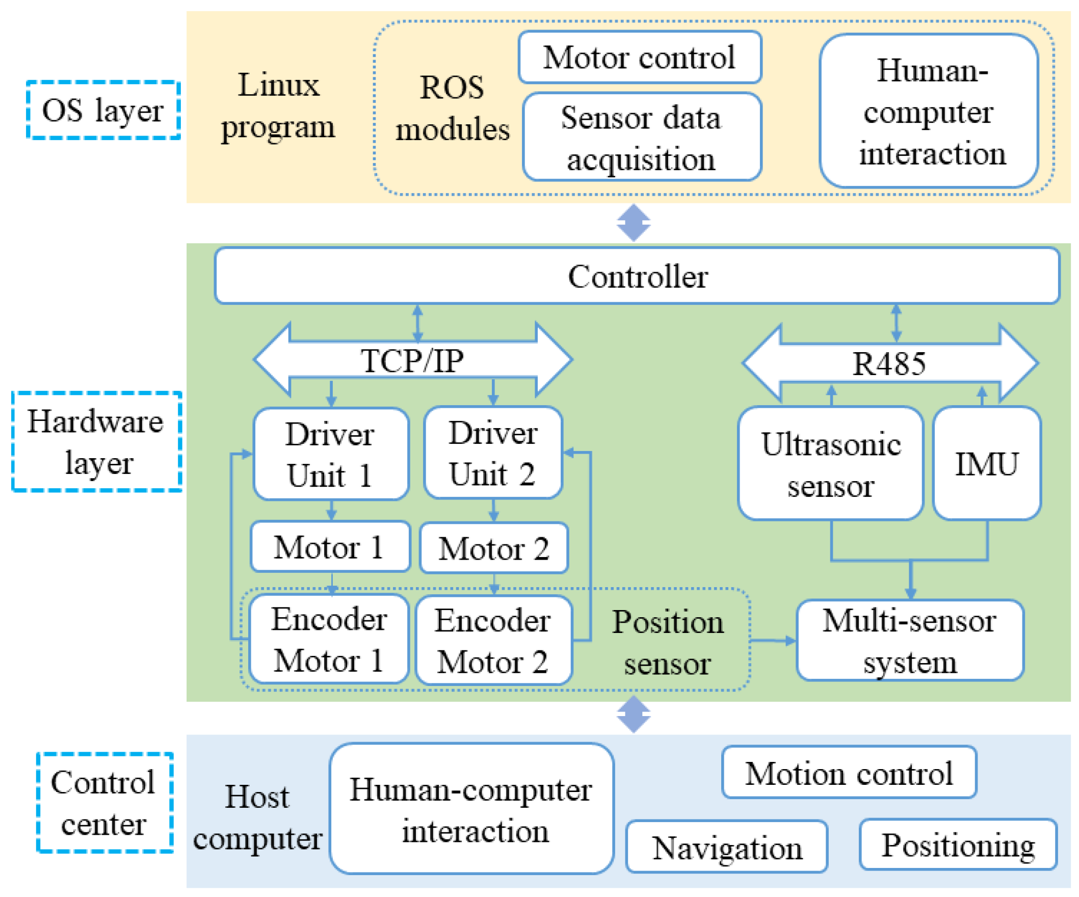
3.2.1. Experimental Setup

The experimental platform is constructed as depicted in Figure 5 to verify the proposed controller design. It mainly equips two direct-drive motors with an absolute rotary encoder, inertial measurement unit (IMU) and ultrasonic sensor. The IMU installed in the WMR is adopted to obtain the orientation, while the absolute rotary encoder is utilized to obtain the robot position. The human–machine interface provides system monitoring, status reporting, touch panels and many other functions. By combining the mentioned simulated process, WMR parameters used in the experiment are the same as those illustrated in Table 1. The software architecture for WMR is shown in Figure 6, and all computations are coded in C language.

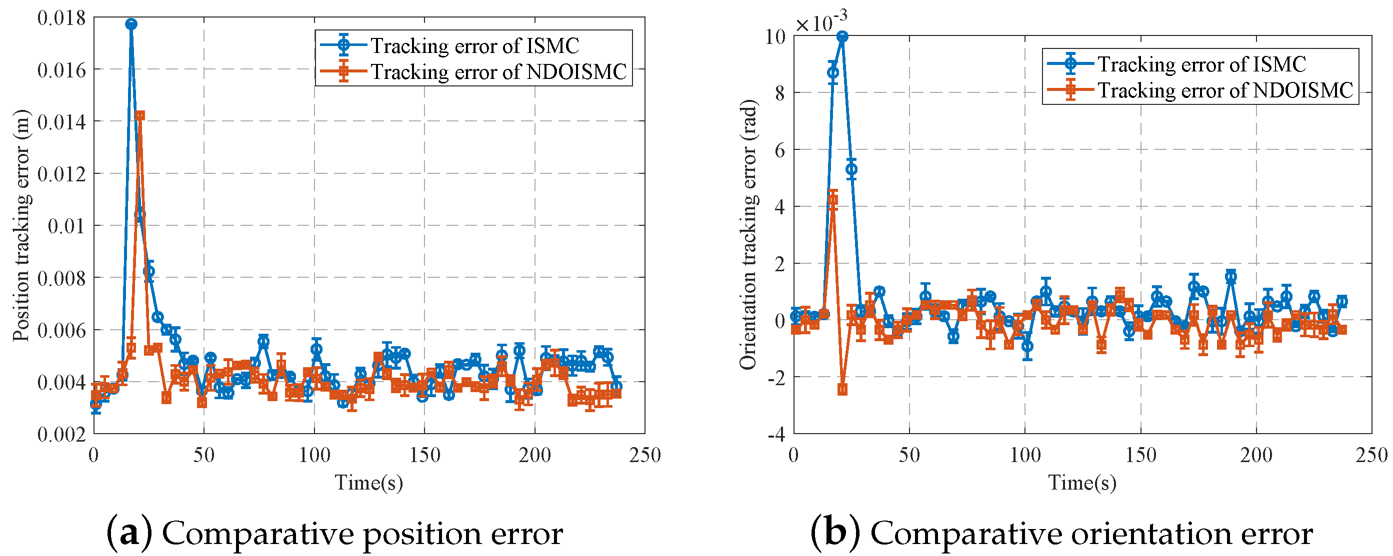
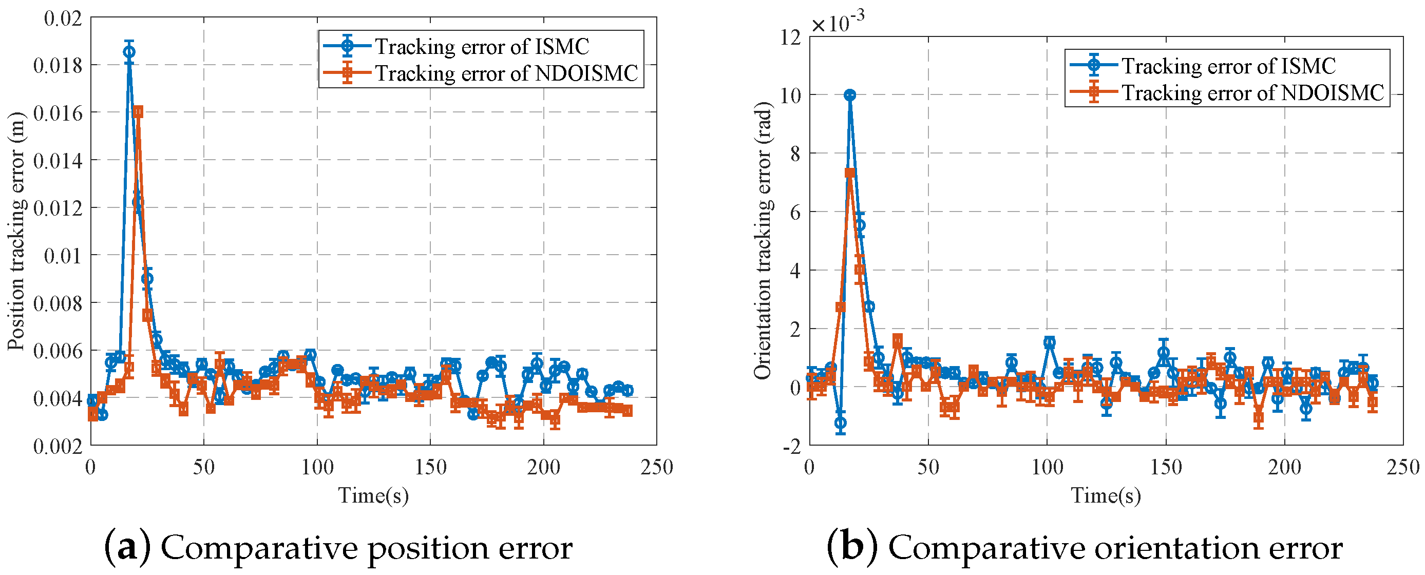
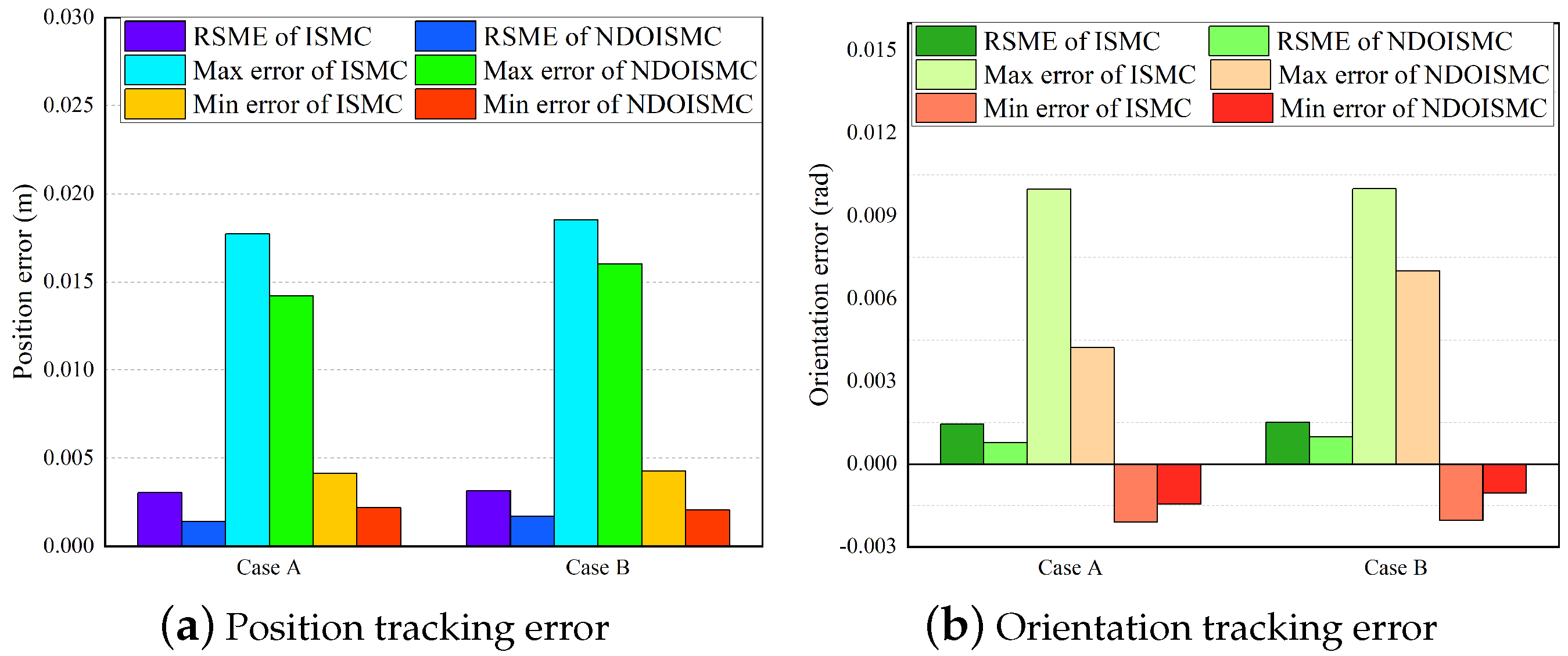
3.2.2. Experimental Results and Discussion

Experiments are conducted under two types of ground conditions: Case A—normal floor surface, Case B—wet floor surface. To evaluate our experimental effect, the position tracking error term is specified as e = e x 2 + e y 2 . Figure 7 and Figure 8 display the position and orientation tracking error for either case. Figure 8a shows that the robust control scheme helps to reduce the position tracking error of WMR under slipping and skidding better, compared with conventional ISMC. In addition, the overshoot of the proposed scheme is apparently smaller. Similarly, it also helps to reduce the orientation tracking error as indicated in Figure 8b. For the wet surface situation, the comparison results of the two methods are provided in Figure 8. It is found that either the position or orientation tracking error employing the proposed robust control scheme is smaller than that of conventional ISMC.
A tentative comparative study is made from different aspects, such as RSME, max error, and min error, to evaluate the performance of NDOISMC further, as in Figure 9. Figure 9a shows that the RSME, and maximum and minimum errors of NDOISMC are also smaller than those of ISMC for position control, regardless of whether the floor is normal or wet. A similar result for orientation control is presented in Figure 9b. Therefore, the proposed NDOISMC can help to improve the path tracking performance for both position and orientation under normal or wet floor conditions well.

4. Conclusions

Considering the wheel skidding and slipping phenomena in the trajectory tracking control problem of WMR, a robust control scheme is studied that can achieve the disturbance attenuation. The kinematic and dynamic model with the perturbed nonholonomic constraints are established. The disturbance observer is developed to counteract the compound disturbance. Based on the disturbance observer and integral sliding mode theory, the robust control scheme at the dynamic level is developed, so the robot system can track the desired velocity asymptotically, and counteract the compound disturbance. The simulation results prove that the proposed control scheme has improvements in the tracking performance relative to the conventional method in terms of trajectory precision, chattering alleviation and disturbance attenuation. Furthermore, the testing platform is built up, and two groups of experiments with normal and wet floor conditions are performed to illustrate the proposed control scheme. The experimental data show that the studied control scheme possesses relatively good tracking characteristics than the conventional scheme.
Although the WMR studied in this paper is a differential-drive mobile robot, the proposed control approach can also be extended to other types of mobile robots or other complex robotic systems, such as wall-climbing robots, mobile manipulators, and so on. The results of this study have implications for motion control, subject to skidding and slipping. The limitations of the proposed approach can be addressed, as the trajectory tracking accuracy depends on the positioning accuracy of the mobile robot system.

Author Contributions

Conceptualization, X.G., L.Y. and C.G.; methodology, X.G. and L.Y.; software, X.G.; validation, X.G. and L.Y.; formal analysis, X.G.; investigation, X.G.; resources, X.G.; data curation, X.G.; writing—original draft preparation, X.G.; writing—review and editing, X.G., L.Y. and C.G.; visualization, X.G.; supervision, L.Y.; project administration, L.Y.; funding acquisition, L.Y. All authors have read and agreed to the published version of the manuscript.

Funding

This research was funded by the Major Project of the New Generation of Artificial Intelligence under grant 2018AAA0102900, the National Natural Science Foundation of China (NSFC) under grant 52130505 and 51875013, the Major Project of Ningbo Science and Technology Innovation 2025 Program under grant 2019B10071, and Fundamental Research Funds for the Central Universities.

Institutional Review Board Statement

Not applicable.

Informed Consent Statement

Not applicable.

Data Availability Statement

Data available on request due to restrictions, e.g., privacy or ethical.

Acknowledgments

The authors are thankful for the support of the Science and Technology on Aircraft Control Laboratory and Research Institute for Frontier Science, Beihang University, Beijing 100191, China.

Conflicts of Interest

The authors declare no conflict of interest.

Abbreviations

The following abbreviations are used in this manuscript:
WMRWheeled mobile robot
NDONonlinear disturbance observer
ISMCIntegral sliding mode controller

References

  1. Filipescu, A.; Minca, E.; Filipescu, A.; Coanda, H.G. Manufacturing technology on a mechatronics line assisted by autonomous robotic systems, robotic manipulators and visual servoing systems. Actuators 2020, 9, 127. [Google Scholar] [CrossRef]
  2. Ding, L.; Li, S.; Liu, Y.J.; Gao, H.; Chen, C.; Deng, Z. Adaptive neural network-based tracking control for full-state constrained wheeled mobile robotic system. IEEE Trans. Syst. Man Cybern. Syst. 2017, 47, 2410–2419. [Google Scholar] [CrossRef]
  3. Noh, M.; Kwon, E.; Park, S.H.; Park, Y.-W. Modeling of attractive force by magnetic wheel used for mobile robot. Actuators 2020, 9, 67. [Google Scholar] [CrossRef]
  4. Tzafestas, S.G. Mobile robot control and navigation: A global overview. J. Intell. Robot. Syst. 2018, 91, 35–58. [Google Scholar] [CrossRef]
  5. Fierro, R.; Lewis, F.L. Control of a nonholomic mobile robot: Backstepping kinematics into dynamics. J. Robot Syst. 1997, 14, 149–163. [Google Scholar] [CrossRef]
  6. Binh, N.T.; Tung, N.A.; Nam, D.P.; Quang, N.H. An adaptive backstepping trajectory tracking control of a tractor trailer wheeled mobile robot. Int. J. Control Autom. Syst. 2019, 17, 465–473. [Google Scholar] [CrossRef]
  7. Yang, J.M.; Kim, J.H. Sliding mode control for trajectory tracking of nonholonomic wheeled mobile robots. IEEE Trans. Robot. Autom. 1999, 15, 578–587. [Google Scholar] [CrossRef] [Green Version]
  8. Liu, K.; Gao, H.; Ji, H.; Hao, Z. Adaptive sliding mode based disturbance attenuation tracking control for wheeled mobile robots. Int. J. Control Autom. Syst. 2020, 18, 1288–1298. [Google Scholar] [CrossRef]
  9. Zhai, J.Y.; Song, Z.B. Adaptive sliding mode trajectory tracking control for wheeled mobile robots. J. Control 2019, 92, 2255–2262. [Google Scholar] [CrossRef]
  10. Ding, L.; Li, S.; Gao, H.; Chen, C.; Deng, Z. Adaptive partial reinforcement learning neural network-based tracking control for wheeled mobile robotic systems. IEEE Trans. Syst. Man Cybern. Syst. 2020, 50, 2512–2523. [Google Scholar] [CrossRef]
  11. Fierro, R.; Lewis, F.L. Control of a nonholonomic mobile robot using neural networks. IEEE Trans. Neural Netw. 1998, 9, 589–600. [Google Scholar] [CrossRef] [Green Version]
  12. Jhang, J.Y.; Lin, C.J.; Lin, C.T.; Young, K.Y. Navigation control of mobile robots using an interval type-2 fuzzy controller based on dynamic-group particle swarm optimization. Int. J. Control Autom. Syst. 2018, 16, 2446–2457. [Google Scholar] [CrossRef]
  13. Guo, Y.; Yu, L.; Xu, J. Robust finite-time trajectory tracking control of wheeled mobile robots with parametric uncertainties and disturbances. Int. J. Syst. Sci. 2019, 32, 1358–1374. [Google Scholar] [CrossRef]
  14. Khalaji, A.K.; Jalalnezhad, M. Robust forward\backward control of wheeled mobile robots. ISA Trans. 2021, 115, 32–45. [Google Scholar] [CrossRef]
  15. Wang, D.W.; Low, C.B. Modeling and analysis of skidding and slipping in wheeled mobile robots: Control design perspective. IEEE Trans. Robot. 2008, 24, 676–687. [Google Scholar] [CrossRef]
  16. Low, C.B.; Wang, D.W. Maneuverability and path following control of wheeled mobile robot in the presence of wheel skidding and slipping. J. Field Robot. 2010, 27, 127–144. [Google Scholar] [CrossRef]
  17. Dixon, W.E.; Dawson, D.M.; Zergeroglu, E. Robust control of a mobile robot system with kinematic disturbances. In Proceedings of the IEEE International Conference on Control Applications. Conference Proceedings (Cat. No.00CH37162), Anchorage, AK, USA, 27 September 2000; pp. 437–442. [Google Scholar]
  18. Dixon, W.E.; Dawson, D.M.; Zergeroglu, E.; Behal, A. Nonlinear control of wheeled mobile robot. In Lecture Notes in Control and Information Sciences; Springer: New York, NY, USA, 2000. [Google Scholar]
  19. Gonzalez, R.; Fiacchini, M.; Alamo, T.; LuisGuzman, J.; Rodriguez, F. Adaptive control for a mobile robot under slip conditions using an LMI-Based approach. Eur. J. Control 2010, 16, 144–155. [Google Scholar] [CrossRef]
  20. Cui, M.; Sun, D.; Liu, W.; Zhao, M.; Liao, X. Adaptive tracking and obstacle avoidance control for mobile robots with unknown sliding. Int. J. Adv. Robot. Syst. 2012, 9, 1–14. [Google Scholar] [CrossRef]
  21. Gao, H.; Song, X.; Ding, L.; Xia, K.; Li, N.; Deng, Z. Adaptive motion control of wheeled mobile robot with unknown slippage. Int. J. Control 2014, 87, 1513–1522. [Google Scholar] [CrossRef]
  22. Li, S.; Ding, L.; Gao, H.; Chen, C.; Liu, Z.; Deng, Z. Adaptive neural network tracking control-based reinforcement learning for wheeled mobile robots with skidding and slipping. Neurocomput 2018, 283, 20–30. [Google Scholar] [CrossRef]
  23. Fernández, C.P.; Cerqueira, J.J.F.; Lima, A.M.N. Nonlinear trajectory tracking controller for wheeled mobile robots by using a flexible auxiliary law based on slipping and skidding variations. Rob. Auton. Syst. 2019, 118, 231–250. [Google Scholar] [CrossRef]
  24. Wang, S.; Zhai, J. A Trajectory Tracking Method for Wheeled Mobile Robots Based on Disturbance Observer. Int. J. Control Autom. Syst. 2020, 18, 2165–2169. [Google Scholar] [CrossRef]
  25. Cui, M. Observer-Based Adaptive Tracking Control of Wheeled Mobile Robots With Unknown Slipping Parameters. IEEE Access 2019, 7, 169646–169655. [Google Scholar] [CrossRef]
  26. Chen, C.; Gao, H.; Ding, L.; Li, W.; Yu, H.; Deng, Z. Trajectory tracking control of WMRs with lateral and longitudinal slippage based on active disturbance rejection control. Rob. Auton. Syst. 2018, 107, 236–245. [Google Scholar] [CrossRef]
  27. Chen, M. Disturbance attenuation tracking control for wheeled mobile robots with skidding and slipping. IEEE Trans. Industr. Inform. 2017, 64, 3359–3368. [Google Scholar] [CrossRef]
  28. Kang, H.S.; Kim, Y.T.; Hyun, C.H.; Park, M. Generalized extended state observer approach to robust tracking control for wheeled mobile robot with skidding and slipping. Int. J. Adv. Robot. Syst. 2013, 10, 1–10. [Google Scholar] [CrossRef]
  29. Kang, H.S.; Hyun, C.H.; Kim, S. Robust tracking control using fuzzy disturbance observer for wheeled mobile robots with skidding and slipping. Int. J. Adv. Robot. Syst. 2014, 11, 1–11. [Google Scholar] [CrossRef] [Green Version]
  30. Kanayama, Y.; Kimura, Y.; Miyazaki, F.; Noguchi, T. A stable tracking control method for an autonomous mobile robot. In Proceedings of the IEEE International Conference on Robotics and Automation, Cincinnati, OH, USA, 13–18 May 1990; pp. 384–389. [Google Scholar]
Figure 1. Schematic diagram of the mobile platform.
Actuators 10 00222 g001
Figure 2. Block diagram of the NDOISMC frame.
Actuators 10 00222 g002
Figure 3. Comparative simulation results for linear trajectory tracking.
Actuators 10 00222 g003
Figure 4. Comparative simulation results for circular trajectory tracking.
Actuators 10 00222 g004
Figure 5. Platform construction of WMR for experiments.
Actuators 10 00222 g005
Figure 6. System architecture of WMR platform.
Actuators 10 00222 g006
Figure 7. Experimental comparison result for Case A: normal floor surface.
Actuators 10 00222 g007
Figure 8. Experimental comparison result for Case B: wet floor surface.
Actuators 10 00222 g008
Figure 9. Comparison result in terms of RSME, max and min errors.
Actuators 10 00222 g009
Table 1. Parameters of the studied WMR system.
Physical MeaningSymbolic NotationValue
Mass of WMRm69.263 Kg
Moment of inertia of WMRI4.729 Kg · m 2
Moment of inertia of each wheelIc0.000718 Kg · m 2
Wheels radiusr0.0625 m
Half distance between left and right wheelsb0.206 m
Distance between C and Pd0.183 m
Publisher’s Note: MDPI stays neutral with regard to jurisdictional claims in published maps and institutional affiliations.

