
Experimental Investigations of Different Loudspeakers Applied as Synthetic Jet Actuators


Department of Thermodynamics, Faculty of Mechanical Engineering and Aeronautics, Rzeszow University of Technology, 35-959 Rzeszów, Poland
*
Author to whom correspondence should be addressed.
Actuators 2021, 10(9), 224; https://0-doi-org.brum.beds.ac.uk/10.3390/act10090224
Submission received: 25 June 2021
/
Revised: 1 September 2021
/
Accepted: 2 September 2021
/
Published: 5 September 2021
(This article belongs to the Special Issue Flow Control by Means of Synthetic Jet Actuators)
Abstract
:The paper presents the preliminary results of the experimental investigation of four various loudspeakers used for driving the synthetic jet actuator. The parameters, characteristic synthetic jet velocity, pressure inside the cavity, device sound pressure level (SPL), and the heat sink thermal resistance, were presented for various input power and driving frequency. The resonance frequency was determined based on electrical impedance. The highest synthetic jet momentum velocity was achieved at diaphragm resonance frequency. The maximum sound pressure level was observed, also at resonant frequency. For the same real power delivered to the actuator and for its resonance frequency, the heat sink thermal resistance had the lowest value for the specific loudspeaker. In turn, the synthetic jet velocity reached maximum for this actuator. For all actuators tested, the sound pressure level was dependent on momentum velocity.
1. Introduction
Synthetic jet (SJ) actuators are a novel, interesting kind of generators of the fluid flow. They have been widely researched since 1990 [1]. SJ actuators generate synthetic jets from the fluid, which is moved by loudspeakers [2,3,4], piezoelectric transducers [5,6,7,8], pistons [9], or plasma [10]. SJ may be useful in heat transfer enhancement processes [11,12,13,14,15], mixing [16], flow control [17,18] or propulsions [19]. Recently, the synthetic jets were extensively investigated. A number of literature positions on SJ properties and applications can be found. As exemplary references, the review articles [20,21] are cited. The first position [20] includes a brief review of heat transfer enhancement using SJ characterized by different parameters. Similarly, the second article [21] presents the review of SJ performances and parameters that can impact the fluid flow and heat transfer processes.
The SJ actuator is a simple apparatus, also known as a zero-net-mass-flux device due to lack of fluid mass addition to the working system. It consists of three basic parts: a cavity with an orifice, diaphragm, and the element causing the diaphragm deflection. In the case of applying a loudspeaker, the synthetic jet is formed when the working fluid is periodically sucked into and ejected from an orifice in a cavity by the diaphragm vibrations, which are caused by a loudspeaker. Thus, the loudspeaker parameter, as well as orifice and cavity geometry, will affect the synthetic jet actuator characteristics.
Heat transfer enhancement with the use of synthetic jet obtains maximum at a specific axial distance between the cooled object and orifice [12,13,14]. This distance causes the increase of the total space occupied by the cooling device. A possible solution was presented in [22], where the heat sink was located in the synthetic jet actuator cavity, which resulted in a great reduction of the device’s space requirement.
In the present paper, the authors report the results of the preliminary investigations of four loudspeakers used as synthetic jet actuators for the heat sink heat transfer enhancement. It is a continuation of the research presented in [22,23,24], where only one loudspeaker was tested. The synthetic jet velocity, pressure inside the cavity, device sound pressure level, and the heat sink thermal resistance were tested. Various input powers and driving frequencies of SJA were applied. The basic thermal, flow, and acoustics performances for the SJA with various types of loudspeakers were obtained.
2. Materials and Methods
In the present work, four types of tested loudspeakers were applied as SJ actuators and are depicted in Table 1.
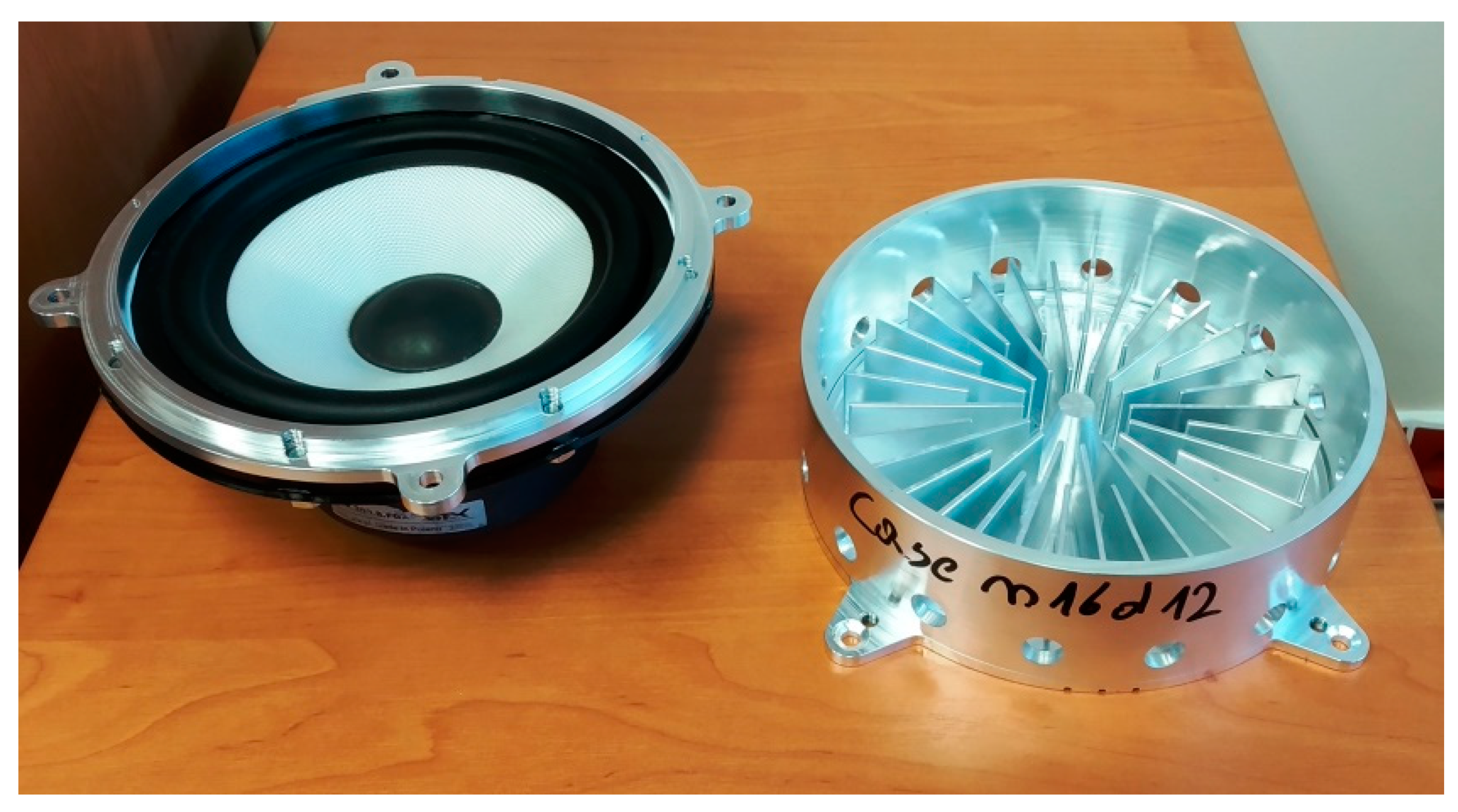
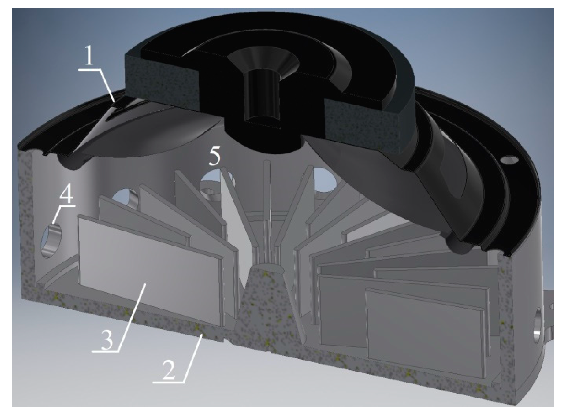
The photo of the heat sink integrated with the SJA is presented in Figure 1 and the cross section is presented in Figure 2. The enclosure of the heat sink was based on a cylinder with outer and inner diameter equal to 180 mm and 170 mm, respectively. The height of the enclosure was 50 mm. Made of milled aluminum, the enclosure featured 32 fins of 2-mm thickness, 16 with a length of 42 mm and 16 with a length 57 mm. A total of 16 orifices with the diameter of 10 mm and length of 5 mm were arranged at equal, angular intervals on the cylindrical surface of the outer ring. The abovementioned, four different models of loudspeakers were used to set the air of the room temperature and atmospheric pressure as the working fluid in motion.
SJ actuators were supplied with a sinusoidal signal from RIGOL DGG4162 function generator (Puyuan Jingdian Technology Co., Ltd, Suzhou, China) and amplified by the AUNA CD-708 audio amplifier. Electric parameters of loudspeakers tested were measured with the use of Keithley 2700 multimeter (22-bit) (Tektronix, Beaverton, USA). An accuracy of measurements of the effective voltage was better than 0.2% of the value measured. The effective current was determined indirectly by the measure of the voltage drop across the standard resistor 1 Ω (±0.01%). In turn, measurements of the apparent power were performed with an accuracy ±0.25% of the set value.
The ambient temperature in the laboratory room was controlled with an air conditioning system. The atmospheric pressure was measured with the Honeywell HPB200W2DA-B (Plymouth MN, USA) barometer with an accuracy of ±40 Pa while the ambient temperature measurement was performed with the use of the ATU 08 constant current thermometer with an accuracy of ±0.5 K. During measurements, the ambient temperature was in the range of 20–23 °C and the barometric pressure was in the range of 990–1002 hPa. For obtaining thermal characteristics of the SJA tested, the measuring system described in detail in [23,24] was applied.
The heat sink base temperature and ambient temperature were measured with the K-type thermocouples (AHLBORN, Holzkirchen, Germany) with the reference junction temperature stabilized by the Kaye 170 Ice Point Reference. The voltage signal from thermocouple was measured with a Keithley 2700. The accuracy of the temperature measurement was estimated to be better than ±0.07 K in the considered temperature range [13]. The temperature was measured after the heat sink reached steady state, and the number of measurements was equal to 100.
The synthetic jet velocity was measured with the use of a constant temperature anemometry method. The ATU 08 bridge (Kraków, Poland), which features separate channels for constant temperature anemometry measurements and the channels for temperature fluctuations measurements with cold-wire method, was applied. The probe equipped with two wires—for the fluid velocity and fluid temperature measuring—was used. The measuring system was calibrated in the velocity range of 0.3–49 m/s. The accuracy of measurements was ±0.1 m/s in the range up to 2.6 m/s and ±2% of the measured value in the range of 2.6–49 m/s. The velocity was measured in the isothermal condition (the heater was switched off). The National Instruments NI-USB-6211 card was used for the acquisition of the constant temperature anemometry bridge output signal. The more detailed description of the SJ velocity measurements is included in [23].
The sound pressure level (SPL) was measured with the use of Testo 816-1 (Lenzkirch, Germany) sound level meter. The Testo 816-1 complies with the requirements of IEC 61672-1 Class 2 standard. Its measuring range is 30–130 dB in a frequency range of 20–8000 Hz. Before measurements, the sound level meter was calibrated with the use of a Testo 0554 0452 calibrator. The National Instruments NI-USB-6211 card was used to record the output signal of the meter. The sound level meter was located at a distance of 1 m from the synthetic jet actuator. The measurements were performed according to ISO 3746:2010 standard.
The changes of the pressure inside the SJA cavity were recorded using the GRAS 40PP (Holte, Denmark) microphone with the National Instruments NI 9250 card. Its measuring range is 10–20,000 Hz and 33–128 dB. The typical uncertainty is presented in the Table 2.
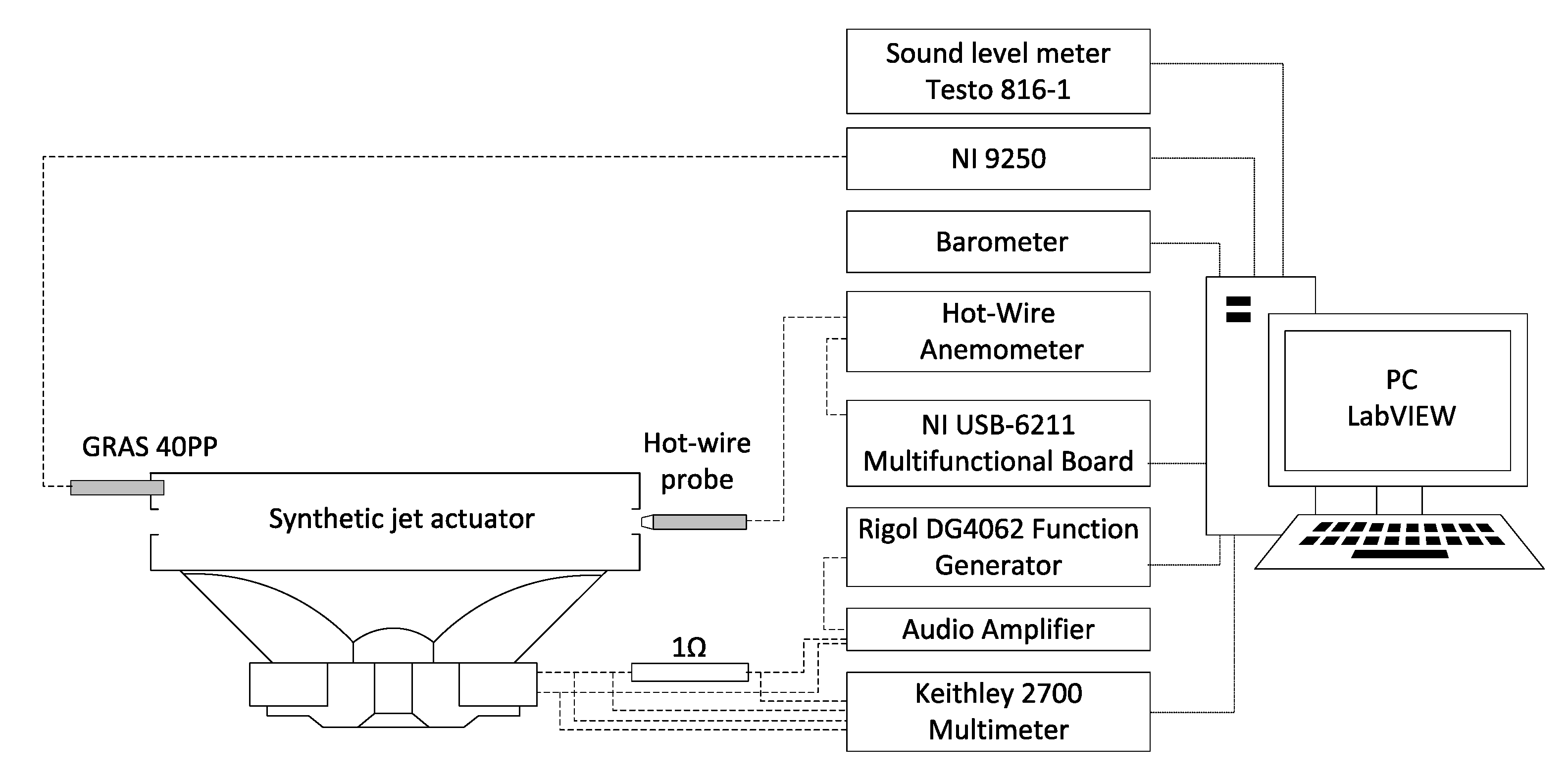
The scheme of the experimental set-up is presented in Figure 3.
3. Results
3.1. Data Reduction
The characteristic parameter of the synthetic jet, the synthetic jet velocity, was obtained as the centerline momentum velocity, according to the formula [25]
where t is an oscillation period of the loudspeaker diaphragm, τ is time, and uc is the centerline velocity at the orifice exit.
Resonance frequencies were received from the impedance vs. frequency dependences, where the electrical impedance is defined as
where E and I are the effective voltage and effective current, respectively.
In turn, the apparent power supplied the SJA is given by
The heat sink thermal resistance was calculated according to the equation
where ∆T is a difference of the heat sink base temperature and the ambient temperature while Q is the thermal power dissipated by the heat sink. It was obtained according to the energy balance of the SJA with integrated heat sink detail, discussed in [23,24].
3.2. Results of Measurements
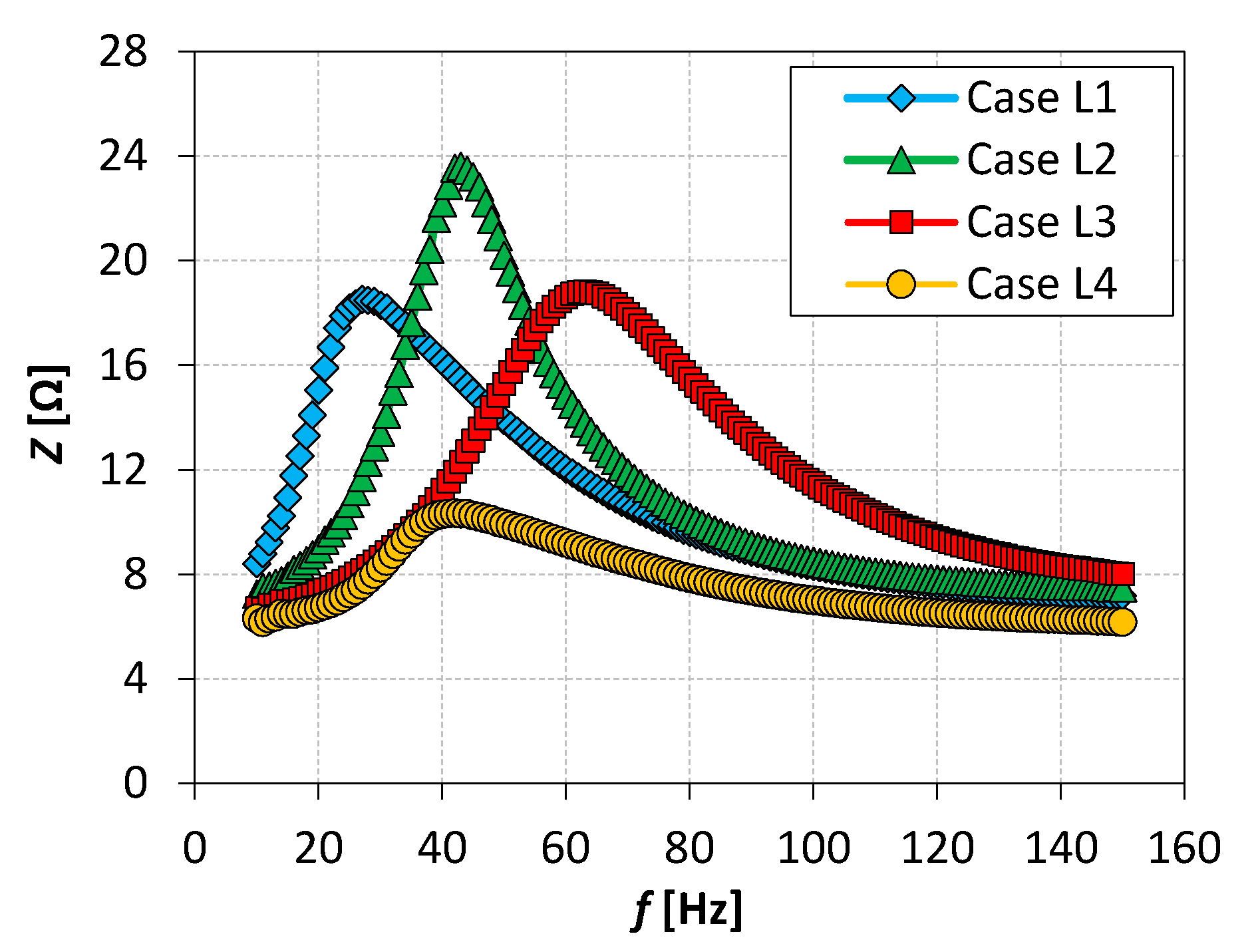
As the first result of the measurements of the parameters characterizing the operation of the SJA with different loudspeakers, the dependence of the impedance vs. the frequency was obtained. The synthetic jet actuator impedance as a function of the frequency is presented in Figure 4.
From the curves presented above, the resonance frequencies characterizing loudspeakers tested were obtained. The results included in Figure 4 concern the case of the apparent power equal to 4 W. As concluded in [25], the resonance frequency did not depend on the actuator supply voltage, and the same may be determined at one value of apparent power. The resonance frequencies obtained were: 27 Hz for loudspeaker L1, 43 Hz for L2, 63 Hz for L3, and 42 Hz for L4.
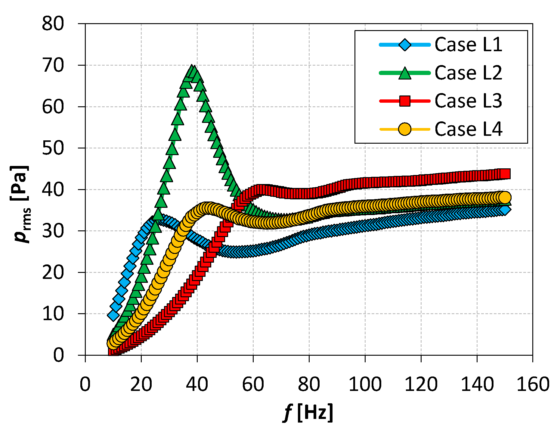
The changes of the pressure inside the SJA cavity were the next measurement results. Figure 5 presents effective values of the pressure in function of the signal frequency at the constant apparent power equal to 1 W. The local maximum of the pressure tested occurred at the resonance frequencies. The highest pressure value characterized the loudspeaker L2.
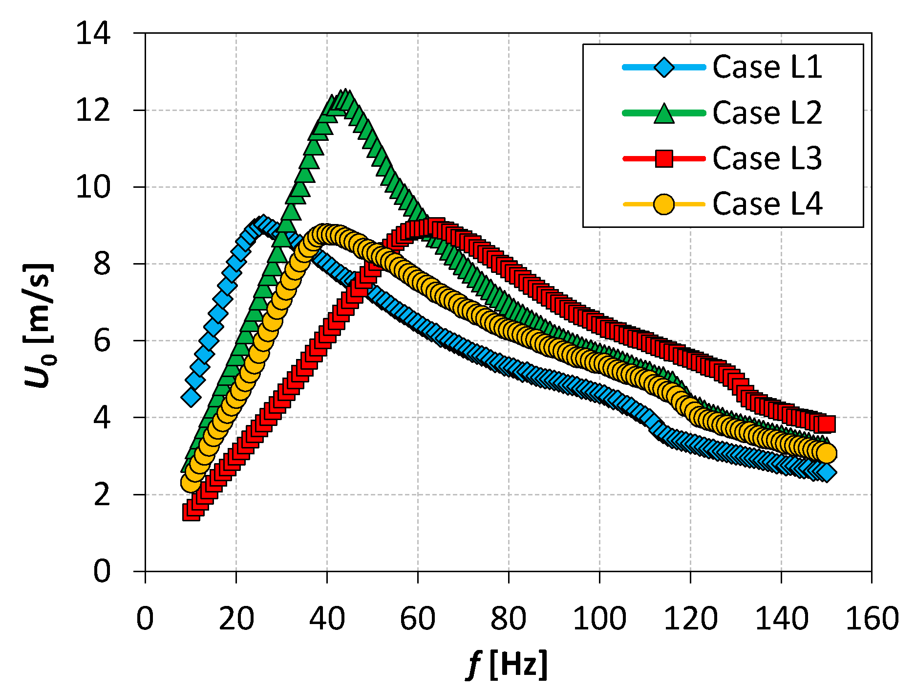
The next measurements performed determined the synthetic jet centerline momentum velocity. The results are presented in Figure 6 in the form of dependence of SJ centerline momentum velocity on the frequency for the loudspeakers considered at the constant apparent power 4 W. As can be seen, the maximum of the velocity occurred at the resonance frequencies and took values equal to about 8.8 m/s for loudspeakers L1, L3, and L4, and about 12.3 m/s for the L2. The synthetic jet characteristic velocity for the synthetic jet actuator with integrated heat sink and for various numbers of orifices and orifice diameters was presented in [24].
The obtained results presented in Figure 4, Figure 5 and Figure 6 show that the best SJ actuator parameters, impedance, effective pressure in the cavity, and SJ centerline momentum velocity were achieved for the resonance frequency in the case of L2 loudspeaker tested.
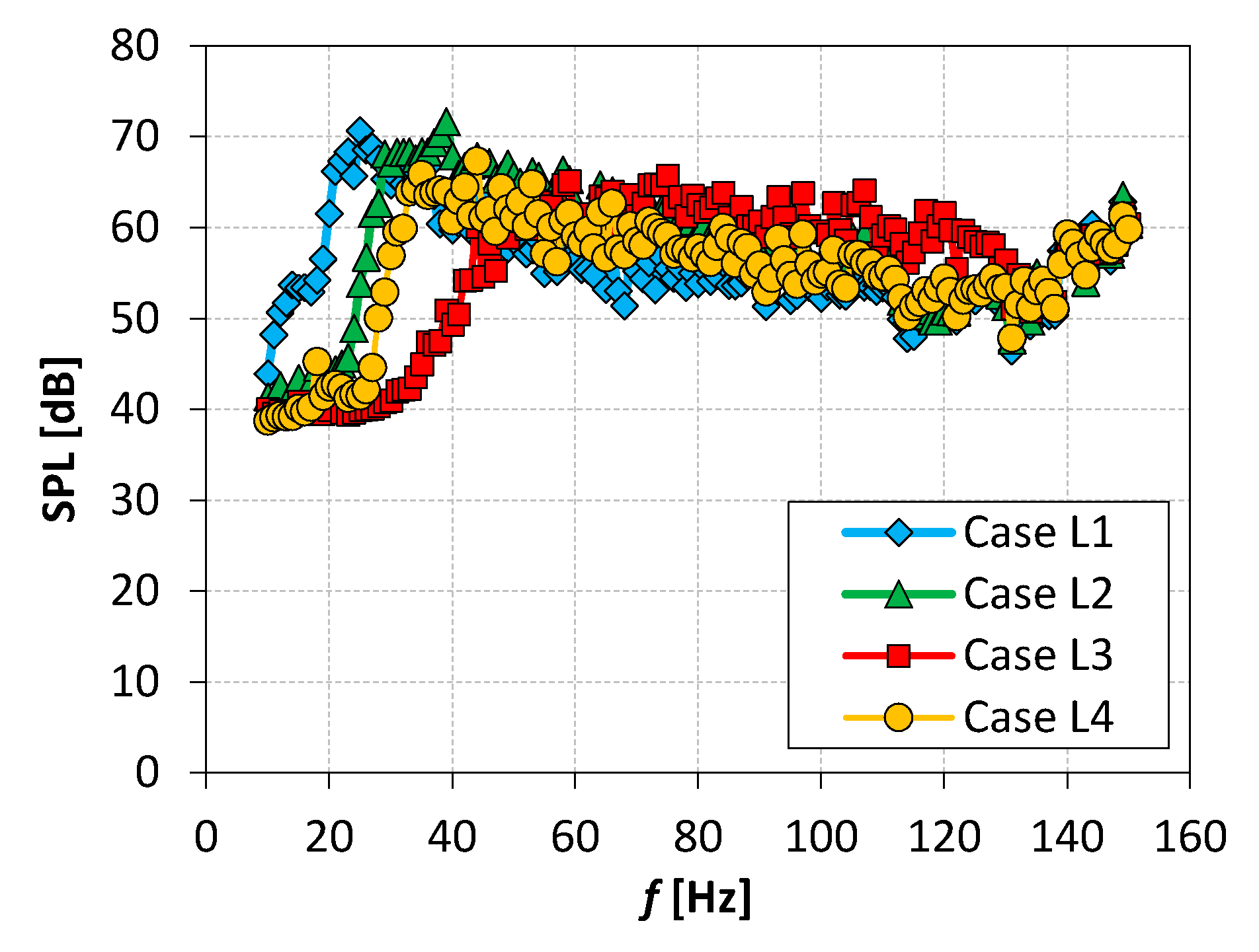
The next parameter measured during the investigations of different loudspeakers, SJ actuators, was the sound pressure level. Figure 7 includes the dependence of SPL on the frequency at the constant apparent power 4.0 W for the four loudspeakers tested. The obtained results showed that the SPL generated by the SJ actuators depended on the frequency [26], and the maximum of SPL occurred for the resonance frequency. A further increase in frequency caused a slight decrease in SPL. For f > 60 Hz, the SPL values remained in the range of 55–65 dB for all loudspeakers considered.
4. Discussion
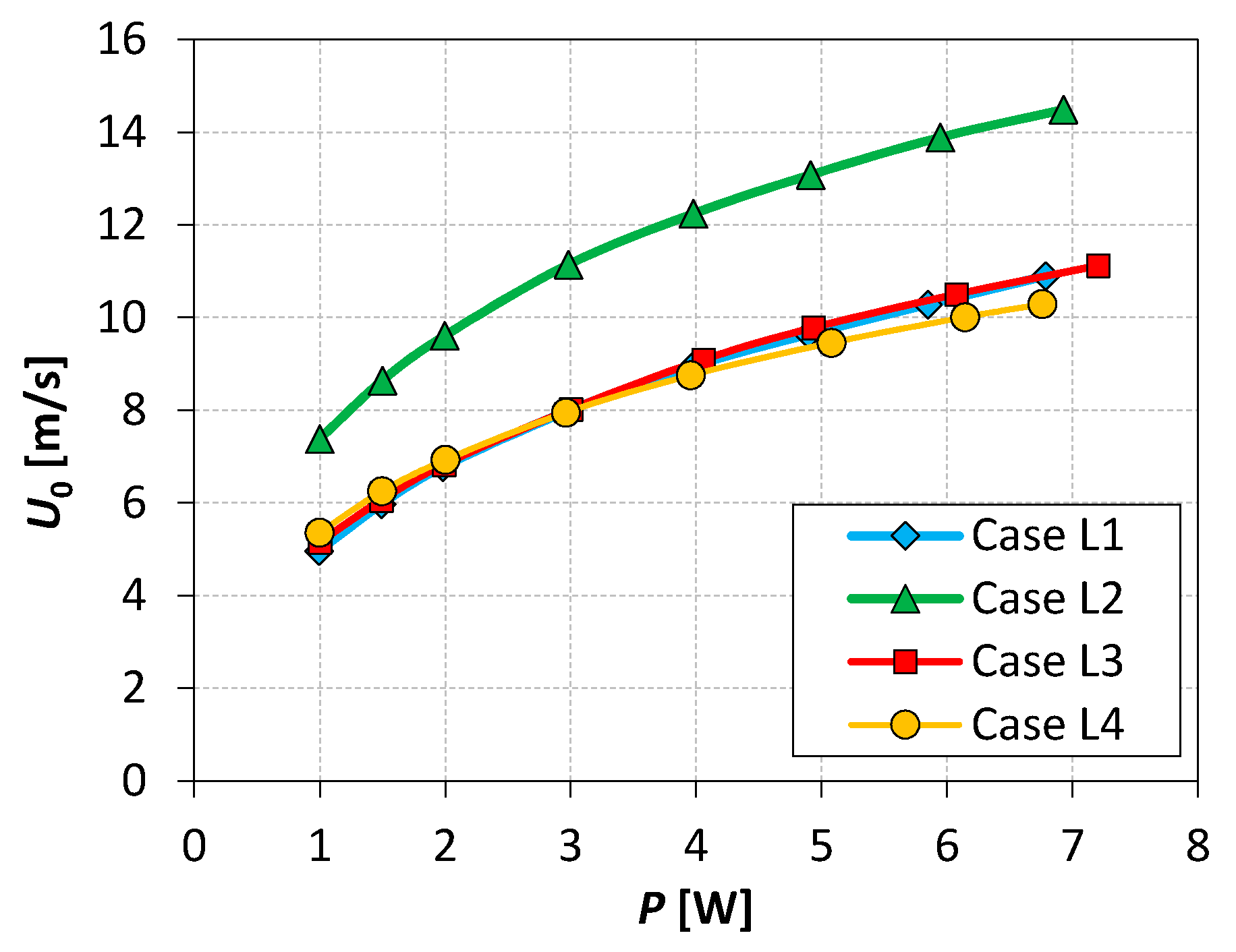
The experimental results presented in the above section were developed in terms of their maximum values received at resonance frequencies. As the first result, the SJ centerline momentum velocity in function of the apparent power was obtained. Figure 8 includes this dependence. As can be seen, characteristics of L1, L3, and L4 loudspeakers coincided, while, for the case of L2, the SJ centerline momentum velocity was much higher than for the other cases.
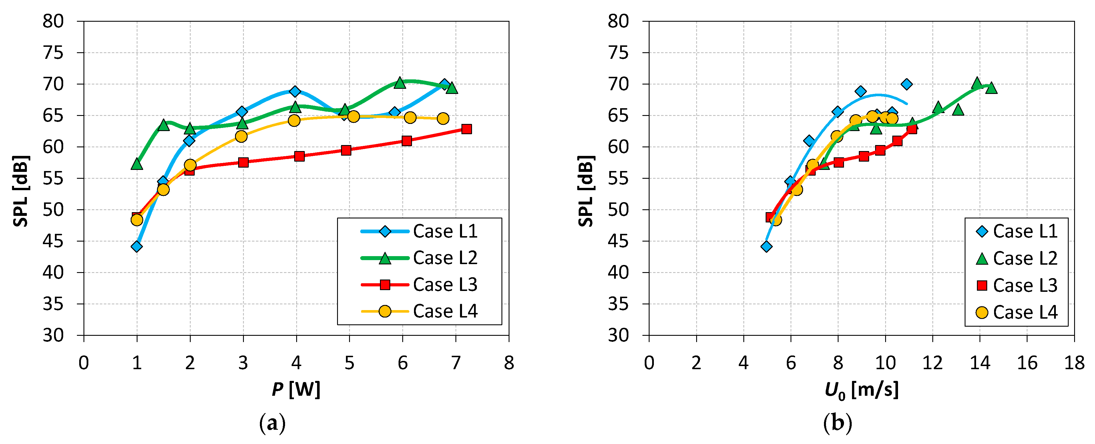
The next stage in the investigations was to find the dependence of the sound pressure level on the apparent power and the centerline momentum velocity under resonance frequency condition for the actuators tested. The results are presented in Figure 9.
Measurement data included in Figure 9a represent the same trend as in the cases investigated in [2,27]—the increase in SPL with the P increasing. Above P = 3.0 W the value of SPL for L1, L2, and L4 actuators fluctuated around the value 65 dB. In the case of L3, the SPL was lower. In turn, the graph in Figure 9b clearly shows the increase in sound pressure level with the characteristic velocity increasing.
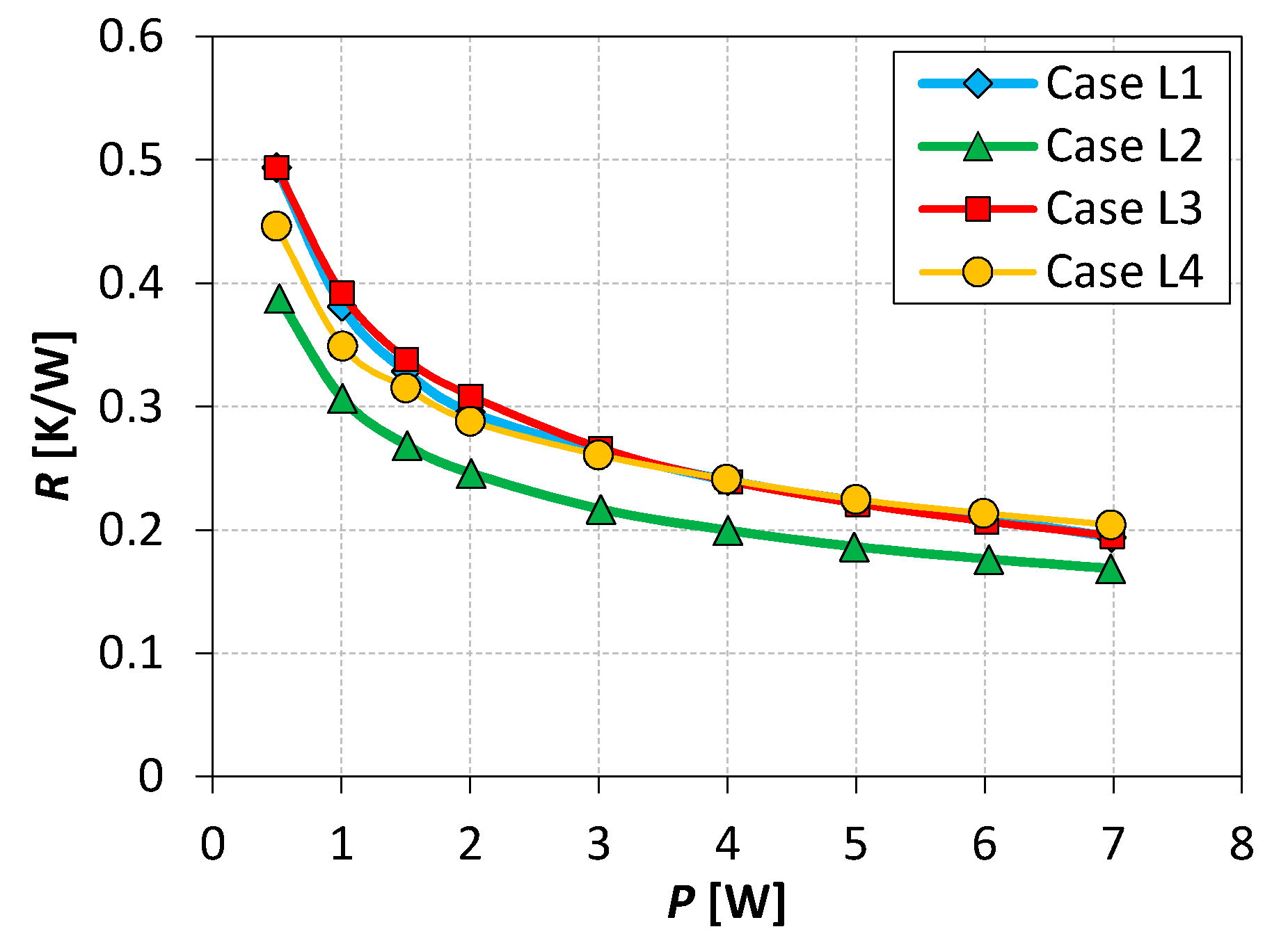
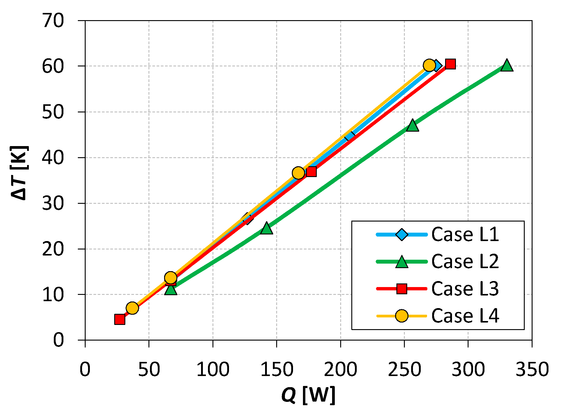
As the last result of the considerations, the thermal characteristics of the actuators integrated with the heat sink were determined. The heat performances are presented in the form of the heat sink thermal resistance in function of the apparent power at the resonance frequency (Figure 10) and the heat sink temperature difference in function of the dissipated thermal power (Figure 11). The heat sink was characterized by the thermal resistance equal to 1.4 K/W [23]. Thus, in the case of the loudspeaker L2, the thermal resistance was reduced to 0.17 K/W at the power P = 7 W, which gave the 8.2 times better cooling compared to free convection characterizing the heat sink operation without the SJ actuator. The L1, L3, and L4 loudspeakers achieved the comparable value of thermal resistance of about 0.2 K/W at P = 7 W. In summary, the actuator L2 allowed, at the same apparent power, the reduction in thermal resistance of about 18%. Presented in Figure 11 is the dependence of ∆T on thermal power dissipated, showing the similar tendency, which was an obvious consequence of the previous relationship. Characteristics of actuators L1, L3, and L4 were similar, while for L2 there was a significant difference. Under maximum ∆T equal to 60 K, the thermal power dissipated by the heat sink cooled with synthetic jets was about 275 W for L1, L3, and L4 actuators applied. The value of Q achieved 330 W in the case of the L2 loudspeaker tested.
The performed preliminary investigations of four loudspeakers used as synthetic jet actuators showed the impact of the loudspeaker type on the basic SJ actuators’ characteristics. The flow and acoustic performances, synthetic jet centerline momentum velocity, pressure inside the cavity, and device sound pressure level, were investigated. Additionally, thermal characteristics of the heat sink integrated with the SJ actuators tested were obtained. The presented results will be useful for synthetic jet actuator optimization, especially from the point of energy conversion.
5. Conclusions
The different loudspeakers resulted in the different synthetic jet actuator performances. From the energetic point of view, the best actuator is characterized by high energy conversion; thus, the same input power generated high cavity pressure and high characteristic velocity. High synthetic jet velocities corresponded with enhanced heat transfer process from the heat sink.
Author Contributions
Conceptualization, P.G. and J.W.; methodology, P.G. and J.W.; software, validation, formal analysis, P.G. and J.W.; investigation, P.G.; resources, J.W. and P.G.; writing—original draft preparation, J.W.; writing—review and editing, J.W.; visualization, P.G. and J.W.; supervision J.W.; project administration, funding acquisition, P.G. Both authors have read and agreed to the published version of the manuscript.
Funding
This work was supported by the National Center for Research and Development, Poland Grant No.: LIDER/6/0024/L-10/18/NCBR/2019.
Institutional Review Board Statement
Not applicable.
Informed Consent Statement
Not applicable.
Data Availability Statement
Some or all data generated or used during the study are available from the corresponding author by request.
Conflicts of Interest
The authors declare no conflict of interest.
References
- Glazer, A.; Amitay, M. Synthetic jets. Annu. Rev. Fluid Mech. 2002, 34, 503–529. [Google Scholar] [CrossRef]
- Smyk, E.; Gil, P.; Gałek, R.; Przeszłowski, Ł. Acoustic and Flow Aspects of Novel Synthetic Jet Actuator. Actuators 2020, 9, 100. [Google Scholar] [CrossRef]
- Smyk, E.; Wilk, J.; Markowicz, M. Synthetic Jet Actuators with the Same Cross-Sectional Area Orifices-Flow and Acoustic Aspects. Appl. Sci. 2021, 11, 4600. [Google Scholar] [CrossRef]
- Kordík, J.; Trávníček, Z. Novel nozzle shapes for synthetic jet actuators intended to enhance jet momentum flux. Actuators 2018, 7, 53. [Google Scholar] [CrossRef] [Green Version]
- Gallas, Q.; Holman, R.; Nishida, T.; Carrol, B.; Sheplak, M.; Cattafesta, L. Lumped Element Modeling of Piezoelectric-Driven Synthetic Jet Actuators. AIAA J. 2003, 41, 240–247. [Google Scholar] [CrossRef] [Green Version]
- Chiatto, M.; Capuano, F.; Coppola, G.; De Luca, L. LEM characterization of synthetic jet actuators driven by piezoelectric element: A review. Sensors 2017, 17, 1216. [Google Scholar] [CrossRef] [Green Version]
- Palumbo, A.; Chiatto, M.; De Luca, L. Measurements versus numerical simulations for slotted synthetic jet actuator. Actuators 2018, 7, 59. [Google Scholar] [CrossRef] [Green Version]
- Zhang, B.; Liu, H.; Li, Y.; Liu, H.; Dong, J. Experimental Study of Coaxial Jets Mixing Enhancement Using Synthetic Jets. Appl. Sci. 2021, 11, 803. [Google Scholar] [CrossRef]
- Liu, Z.; Hong, L. Numerical Study of a novel Piston-type synthetic jet actuator with a quick-return characteristic. IOP Conf. Ser. Mater. Sci. Eng. 2017, 187, 012030. [Google Scholar] [CrossRef]
- Zong, H.; Kotsonis, M. Effect of slotted exit orifice on performance of plasma synthetic jet actuator. Exp. Fluids 2017, 58, 17. [Google Scholar] [CrossRef] [Green Version]
- Chaudhari, M.; Puranik, B.; Agrawal, A. Heat transfer characteristic of synthetic jet impingement cooling. Int. J. Heat Mass Transf. 2010, 53, 1057–1069. [Google Scholar] [CrossRef]
- Greco, C.S.; Paolillo, G.; Ianiro, A.; Cardone, G.; De Luca, L. Effects of the stroke length and nozzle-to-plate distance on synthetic jet impingement heat transfer. Int. J. Heat Mass Transf. 2018, 117, 1019–1031. [Google Scholar] [CrossRef]
- Gil, P.; Wilk, J.; Smusz, R.; Gałek, R. Centerline heat transfer coefficient distributions of synthetic jets impingement cooling. Int. J. Heat Mass Transf. 2020, 160, 120147. [Google Scholar] [CrossRef]
- Gil, P.; Wilk, J. Heat transfer coefficients during the impingement cooling with the use of synthetic jet. Int. J. Therm. Sci. 2020, 147, 106132. [Google Scholar] [CrossRef]
- Miro, A.; Soria, M.; Cajas, J.C.; Rodriguez, I.; Moulinec, C. Flow topology and heat transfer analysis of slotted and axisymmetric synthetic impinging jets. Int. J. Therm. Sci. 2021, 164, 106847. [Google Scholar] [CrossRef]
- Wang, P.; Shen, C. Characteristics of mixing enhancement achieved using a pulsed plasma synthetic jet in asupersonic flow. J. Zhejiang Univ. Sci. A 2019, 20, 701–713. [Google Scholar] [CrossRef]
- Asgari, E.; Tadjfar, M. Active Control of Flow over a Rounded Ramp by Means of Single and Double Adjacent Rectangular Synthetic Jet Actuators. Comput. Fluids 2019, 190, 98–113. [Google Scholar] [CrossRef]
- Zong, H.; Chiatto, M.; Kotsonis, M.; De Luca, L. Plasma synthetic jet actuators for active flow control. Actuators 2018, 7, 77. [Google Scholar] [CrossRef] [Green Version]
- Thomas, A.P.; Milano, M.; G’Sell, M.G.; Fischer, K.; Burdick, J. Synthetic jet propulsion for small underwater vehicles. In Proceedings of the 2005 IEEE International Conference on Robotics and Automation, Barcelona, Spain, 18–22 April 2005; pp. 181–187. [Google Scholar]
- Arshad, A.; Jabbal, M.; Yan, Y. Synthetic jet actuators for heat transfer enhancement—A critical review. Int. J. Heat Mass Transf. 2020, 146, 118815. [Google Scholar] [CrossRef]
- Krishan, G.; Aw, K.C.; Sharma, R.N. Synthetic jet impingement heat transfer enhancement—A review. Appl. Therm. Eng. 2019, 149, 1305–1323. [Google Scholar] [CrossRef]
- Gil, P. Performance of special type heat sink with an integrated synthetic jet actuator. E3S Web Conf. 2019, 100, 00017. [Google Scholar] [CrossRef] [Green Version]
- Gil, P. Experimental investigation on heat transfer enhancement of air-cooled heat sink using multiple synthetic jets. Int. J. Therm. Sci. 2021, 166, 106949. [Google Scholar] [CrossRef]
- Gil, P.; Smyk, E.; Gałek, R.; Przeszłowski, Ł. Thermal, flow and acoustic characteristics of the heat sink integrated inside the synthetic jet actuator cavity. Int. J. Therm. Sci. 2021, 170, 107171. [Google Scholar] [CrossRef]
- Gil, P.; Wilk, J.; Korzeniowski, M. Helmholtz Resonance Frequency of the Synthetic Jet Actuator. Appl. Sci. 2021, 11, 5666. [Google Scholar] [CrossRef]
- Bhapkar, U.S.; Srivastava, A.; Agraval, A. Acoustic and heat transfer characteristics of an impinging elliptical synthetic jet generated by acoustic actuator. Int. J. Heat Mass Transf. 2014, 79, 12–23. [Google Scholar] [CrossRef]
- Smyk, E.; Markowicz, M. Acoustic and flow aspects of synthetic jet actuators with chevron orifices. Appl. Sci. 2021, 11, 652. [Google Scholar] [CrossRef]
Figure 1.
Heat sink integrated with the enclosure of SJA.

Figure 2.
The cross section of SJA with integrated heat sink, 1, loudspeaker; 2, heat sink base; 3, fin; 4, orifice; 5, cavity.
Figure 2.
The cross section of SJA with integrated heat sink, 1, loudspeaker; 2, heat sink base; 3, fin; 4, orifice; 5, cavity.

Figure 3.
The scheme of the experimental set-up.

Figure 4.
SJA impedance as a function of frequency, P = 4.0 W.

Figure 5.
Effective pressure in the SJA cavity as a function of frequency, P = 1.0 W.

Figure 6.
SJ jet centerline momentum velocity as a function of frequency, P = 4.0 W.

Figure 7.
Sound pressure level generated at P = 4.0 W.

Figure 8.
SJ centerline momentum velocities at individual resonance frequency in function of apparent power.
Figure 8.
SJ centerline momentum velocities at individual resonance frequency in function of apparent power.

Figure 9.
Sound pressure level of the actuators under resonance frequency condition in function of: (a) apparent power; (b) centerline momentum velocity.
Figure 9.
Sound pressure level of the actuators under resonance frequency condition in function of: (a) apparent power; (b) centerline momentum velocity.

Figure 10.
Heat sink thermal resistances as a function of power delivered to the actuator at individual resonance frequency.
Figure 10.
Heat sink thermal resistances as a function of power delivered to the actuator at individual resonance frequency.

Figure 11.
Heat sink temperature difference as a function of dissipated thermal power, P = 7.0 W, at individual resonance frequency.
Figure 11.
Heat sink temperature difference as a function of dissipated thermal power, P = 7.0 W, at individual resonance frequency.


Table 1.
Specification of loudspeakers tested.
| Case and Type of Loudspeaker | Impedance, R [Ω] | BL, [T.m] | SPL, [dB] | Mass of the Diaphragm Mms [g] | |
|---|---|---|---|---|---|
| L1 | W.18.200.8.FGX | 6.1 | 7.5 | 89 | 16.5 |
| L2 | W.18.180.8.FCX_v2 | 5.5 | 7.1 | 90 | 14.6 |
| L3 | M.18.200.8.MCX | 5.7 | 7.4 | 92 | 13.5 |
| L4 | M.18.150.8.MC | 5.6 | 3.9 | 90 | 10.8 |
Table 2.
Typical uncertainty.
| Name | Relative Uncertainty | Absolute Uncertainty |
|---|---|---|
| P (apparent power) | ±0.55% | - |
| U0 (momentum velocity) | ±5.0% | - |
| ΔT (temperature difference) | - | ±0.25 K |
| R(thermal resistance) | ±3.4% | - |
| Q(thermal power) | ±1.5% | - |
Publisher’s Note: MDPI stays neutral with regard to jurisdictional claims in published maps and institutional affiliations. |
© 2021 by the authors. Licensee MDPI, Basel, Switzerland. This article is an open access article distributed under the terms and conditions of the Creative Commons Attribution (CC BY) license (https://creativecommons.org/licenses/by/4.0/).
Share and Cite
MDPI and ACS Style
Gil, P.; Wilk, J. Experimental Investigations of Different Loudspeakers Applied as Synthetic Jet Actuators. Actuators 2021, 10, 224. https://0-doi-org.brum.beds.ac.uk/10.3390/act10090224
AMA Style
Gil P, Wilk J. Experimental Investigations of Different Loudspeakers Applied as Synthetic Jet Actuators. Actuators. 2021; 10(9):224. https://0-doi-org.brum.beds.ac.uk/10.3390/act10090224
Chicago/Turabian StyleGil, Paweł, and Joanna Wilk. 2021. "Experimental Investigations of Different Loudspeakers Applied as Synthetic Jet Actuators" Actuators 10, no. 9: 224. https://0-doi-org.brum.beds.ac.uk/10.3390/act10090224
Note that from the first issue of 2016, this journal uses article numbers instead of page numbers. See further details here.