
Intelligent Vehicle Lateral Control Method Based on Feedforward + Predictive LQR Algorithm


College of Engineering, Anhui Agricultural University, Hefei 230036, China
*
Authors to whom correspondence should be addressed.
Actuators 2021, 10(9), 228; https://0-doi-org.brum.beds.ac.uk/10.3390/act10090228
Submission received: 4 August 2021
/
Revised: 2 September 2021
/
Accepted: 7 September 2021
/
Published: 9 September 2021
(This article belongs to the Section Actuators for Land Transport)
Abstract
:Aiming at the problems of control stability of the intelligent vehicle lateral control method, single test conditions, etc., a lateral control method with feedforward + predictive LQR is proposed, which can better adapt to the problem of intelligent vehicle lateral tracking control under complex working conditions. Firstly, the vehicle dynamics tracking error model is built by using the two degree of freedom vehicle dynamics model, then the feedforward controller, predictive controller and LQR controller are designed separately based on the path tracking error model, and the lateral control system is built. Secondly, based on the YOLO-v3 algorithm, the environment perception system under the urban roads is established, and the road information is collected, the path equation is fitted and sent to the control system. Finally, the joint simulation is carried out based on CarSim software and a Matlab/Simulink control model, and tested combined with hardware in the loop test platform. The results of simulation and hardware-in-loop test show that the transverse controller with feedforward + predictive LQR can effectively improve the accuracy of distance error control and course error control compared with the transverse controller with feedforward + LQR control, LQR controller and MPC controller on the premise that the vehicle can track the path in real time.
1. Introduction
Intelligent driving vehicles are not only a research hotspot in the field of vehicle engineering but are also a new direction in the development of automobile industry for the future [1,2]. Vehicle motion control is the core to realize intelligent driving and lateral motion control is an important factor in ensuring vehicle driving safety, handling stability and other performance [3,4]. Its research has strong theoretical research significance and engineering application value [5].
In recent years, many scholars have combined intelligent driving vehicle system design and vehicle dynamics models to conduct research into lateral motion control methods, and have achieved fruitful results. Woo Young Choi et al. designed a lateral control method for autonomous vehicles based on efficient model predictive control (MPC), and verified the effectiveness of the method through simulation experiments [6]. Ningyuan Guo et al. designed a vehicle tracking control strategy with yaw motion stability. The nonlinear model predictive control (NMPC) method is used to establish an error model through the vehicle motion state, and the stability of the vehicle is improved through experiments and the amount of calculation is reduced [7]. Fen Lin, Yaowen Zhang et al. designed a lateral control method based on a linear time-varying model prediction, combined with the vehicle dynamics system to design the yaw moment control parameters to reasonably distribute the tire driving force, so as to ensure that the vehicle has good yaw stability during path tracking [8]. Anh-Tu Nguyen et al. designed a fuzzy static output feedback control vehicle path tracking control method. The controller is designed as an optimization problem under linear matrix inequality, and it can be effectively solved through simulation [9]. Aiming at the nonlinear and time-varying characteristics of vehicle systems, Chen C, Lv J and others proposed an improved control method combining an input–output linear algorithm and an adaptive fuzzy sliding mode control algorithm to improve the robustness of the system [10]. Matthew Brown proposed a lateral control method combining local path planning and path tracking based on model predictive control. Taking the real-time position and speed state output in the vehicle dynamics model as the control quantity, the first-order hold discrete method is used to ensure safe obstacle avoidance and to realize motion stability and obstacle avoidance ability by using environmental information and a vehicle model [11]. Zhang W first analyzed the vehicle dynamic tracking error model and studied a robust steering torque control strategy for the automatic driving vehicle lateral tracking function. Hardware loop environment built by ETAS labcar and Matlab/Simulink and test analysis under various conditions [12]. Chunjiang Bao proposed a steering torque control method based on a model predictive control algorithm. Combining a steering system model and a steering resistance torque model in vehicle dynamics, a model predictive controller model with vehicle state parameters as feedback variables was used to simulate Lane holding based on Carsim and Simulink control models, and a hardware in-loop test is performed on the ring test platform based on CarSim/LabVIEV-RT hardware [13]. The literature [14,15,16,17,18,19,20,21,22] concerning linear quadratic regulators respectively designs and tests the lateral controller of intelligent vehicles based on Linear quadratic regulator (LQR), MPC, NMPC, LPV control methods, LMI robust control method, sliding film variable structure, PID and other control methods, and achieves good control effect in a specific test scenario. In conclusion, the design of a control method is the core of the whole control system for the lateral control of intelligent vehicles. At present, research into control methods mainly focuses on a single factor and achieves certain results.
The LQR control method is a classical control method, which has been applied in many fields [23,24]. Snider proposed the application of the LQR control method in intelligent vehicle path tracking in 2009, took the vehicle centroid as the control point, established the system model with road curvature disturbance, and designed an LQR controller [25]. Although the control method can make the system tend to be stable, it does not consider the disturbance term and has a systematic error. Therefore, NR kapania proposed a feedforward + feedback steering controller. The design first considered the establishment of a nonlinear vehicle dynamics model and the construction of a feedforward control method controller. At the same time, it showed a trend of significant increase in steady-state path deviation at high speed [26]. Xu et al. proposed adding a road curvature feedforward link on the basis of an LQR feedback control to eliminate the steady-state error of lateral displacement [27]. To sum up, the advantage of LQR in the lateral control of intelligent driving is that when the vehicle yaws during the driving process, it can ensure that the intelligent vehicle tracking control system can be close to a balanced state without consuming too much energy. The research based on the LQR control method has been widely used in intelligent vehicles, but there is still a need to improve control stability.
Aiming at the stability problem of intelligent driving lateral motion control, considering the interference factors of the actual environment, this paper proposes a lateral control method with feedforward + predictive LQR. Through simulation and experimental comparison, it is verified that the accuracy of the control method proposed in this paper is better than the existing control methods.
The main contributions of this paper are:
1. Based on the vehicle dynamics tracking error model, a lateral control method based on feedforward + predictive LQR is proposed.
2. This paper introduces the consideration of the actual environment’s influence and interference factors, and combines the designed control method with the actual road environment.
3. A hardware-in-the-loop test platform was established on the basis of software simulation, and test verification was carried out. The hardware-in-the-loop test results show that the control method proposed in the paper improves the accuracy of vehicle path tracking control.
4. This method provides a new idea for studying the lateral control stability control of intelligent driving vehicles.
2. Establishment of a Vehicle Dynamics Model
Vehicle Dynamics Tracking Error Model
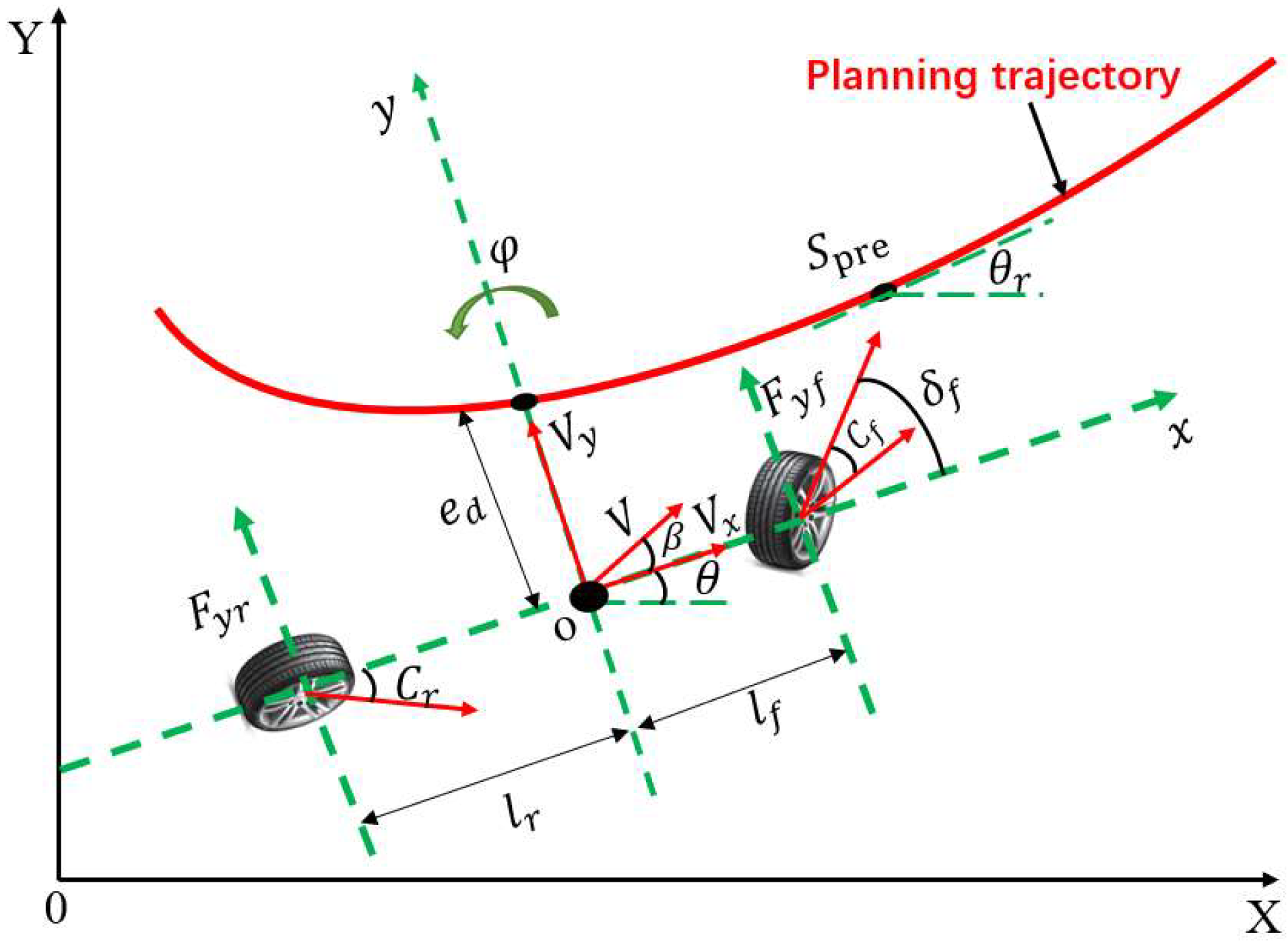
Because the vehicle system is a complex system with uncertainties of non-linearity, time delay and time-varying parameters [28], in a vehicle lateral control, the main research is focused on vehicle lateral dynamic characteristics. In this paper, vehicle dynamic model is simplified into a two-degree-of-freedom lateral dynamic model [29,30], as shown in Figure 1. A simplified approximation is made on the basis of the established model. It is assumed that the lateral force and the lateral angle of the tyre is approximately proportional to the small lateral acceleration. It is assumed that the front and rear axle wheel corners are equal to the lateral stiffness.
By analyzing the two degree of freedom vehicle model, assuming that the vehicle speed remains the same and the wheel angle is small, it can be launched as follows:
where: is the mass of the whole vehicle; and are the lateral forces of the front and rear axles of the vehicle respectively; is the moment of inertia of the vehicle around the Z axis; is the yaw rate of the vehicle; and is the distance from the vehicle centroid to the front and rear axles respectively; is the vehicle longitudinal speed; is the vehicle lateral speed. is the front wheel corner of the vehicle.
Set , and the state space equation form of vehicle dynamics during steering can be obtained:
When an intelligent vehicle tracks its path in real time, distance error and course error will occur when planning the path and current position of the vehicle. In actual control, the design controller is required to eliminate these two errors in real time, so that the vehicle can track the planned path in real time. Define the distance between the center of mass of the vehicle and the projection point of the road centerline as the distance error ed, and the deviation between the vehicle and the road direction as the heading error .
According to the distance error , you can calculate as:
where: V is the center of mass of the vehicle speed; is the heading angle of the vehicle; is the theoretical heading angle at the current time.
According to the derivation of vehicle dynamics model, it can be deduced that:, is the sideslip angle of the center of mass.
Set is the approximate heading error, let , Through calculation and simplification in combination with Equation (2), it can be obtained that:
According to heading error , you can get:
For the convenience of calculation, it is considered that , so the approximate heading error is:
Derivation of (7) can be launched:
Substituting Equation (3) into Equations (5) and (8), can be launched :
Available after sorting :
By further transforming the above formula, the state space equation of distance error and approximate heading error in the steering process of the intelligent vehicle can be obtained as follows:
Therefore, gaining the state space equation concerning the tracking error of vehicle dynamics, we obtain the following:
Discretize the continuous state space equation of Equation (12), ignore the influence of , and integrate the two sides of (12) to obtain the following:
According to the integral median theorem, it can be launched:
Use the forward Euler method and the backward Euler method to Formula (10) and simplify and derive:
where: I is the identity matrix; is the sampling period; ;
Ignoring the influence of , the state space equation of the discretized vehicle model tracking error can be expressed as:
where:;
3. Lateral Control System Design
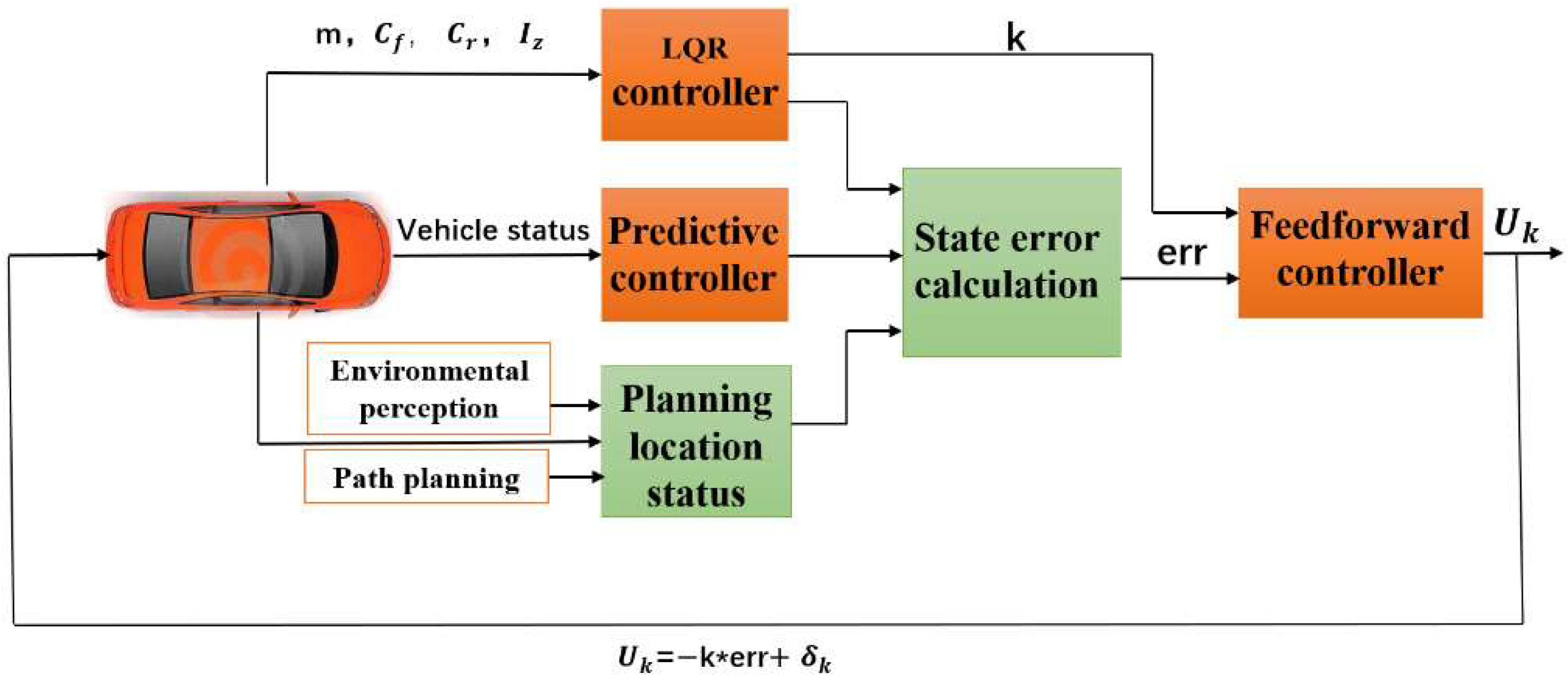
Based on the intelligent vehicle tracking error model, a lateral controller is designed as shown in Figure 2, which restricts the distance error and the course error during the tracking process and eliminates the state error between the current position and the reference position of the intelligent vehicle.
Firstly, the LQR controller is designed by using the established vehicle dynamics tracking error model to output vehicle parameters and the predictive controller is designed by using real-time vehicle status information. Next, the state error is calculated according to the state quantity of the vehicle planning position obtained from the upper environment perception and path planning and the current position information output from the feedforward controller. Second, the feedforward controller calculates the input feedforward through the LQR controller and the state error. Finally, the output is calculated and fed back to the vehicle controller to control the front wheel angle of the vehicle in real time and to control the vehicle to travel according to the planned path.
3.1. LQR Controller Design
The research object of the linear quadratic regulator is the linear system given in the form of a state space equation in modern control theory, and the objective function is the quadratic function of object state and control input [31,32]. The advantage of LQR in intelligent driving lateral control is that when the system state deviates from the equilibrium state due to obstacles or emergencies during vehicle driving, it ensures that the intelligent vehicle tracking control system can approach the equilibrium state without consuming too much energy. Therefore, in intelligent driving, LQR control can realize closed-loop optimal control through state feedback [33]. According to the discretized vehicle dynamics state–space equation built by Equation (16) in the previous section, the LQR controller system performance function is constructed:
where is the state variable of the system; is the control variable of the system; Q is the weighting matrix of state error; and R is the weighting matrix of the control quantity.
The Lagrangian control problem with multiplicative constraints is constructed as follows:
Construct Hamiltonian function so that
Simplify and merge to get:
By deriving Equation (20) and solving the extreme value, it can be obtained as follows:
where, let and be the solution of Riccati equation .
The optimal sequence of feedback control is obtained through iteration, and the control quantity of intelligent driving vehicle LQR controller is obtained as follows:
where is the gain of the LQR controller.
Among them, the weighted matrix parameter Q and parameter R of the LQR controller will have an important impact on the performance of the entire controller. Generally, the values of Q and R are determined according to the test results. According to the lateral controller designed in the paper, the weighting matrices Q and R can be described as:
where: each element in the matrix Q represents the degree of importance attached to the corresponding control target, and correspond to the degree of importance the control system attaches to distance error, distance error change rate, heading error, and heading error change rate respectively. The larger the value, the stronger the control degree of the system. According to trial and error, it is set to , the elements in the matrix R indicate the degree of restriction of the control system to the control quantity, because there is only one control quantity in the text, which is the front wheel of the vehicle Rotation angle, so the element r in the formula is a fixed constant, which is set to 8 in the text according to trial and error.
3.2. Feedforward Controller Design
Incorporating Equation (22) into Equation (12) and discretizing, it can be launched thus:
According to the above formula, if only LQR control is used, the system cannot eliminate the steady-state error no matter what value k is taken in the state space equation; that is, it cannot ensure that the distance error and the heading error of the intelligent vehicle in the process of lateral control are 0. In this paper, the output of the front wheel angle controller is set as the steady-state delta controller to eliminate the front wheel angle . The output of the system is:
When the system reaches the optimal control, that is, the steady-state error needs to be 0, and then bring Equation (25) into Equation (12) and discretizing, it can be launched thus:
It can be concluded from Equation (25) that it is necessary to calculate the appropriate , which makes the steady-state error of the system 0, so as to achieve the optimal control state. Inverse and simplify the calculation of Equation (26) to obtain the equation about the steady-state error of the system:
where: is the steady-state error of distance error; is the steady-state error of approximate heading error.
Therefore, it is necessary to set a feedforward controller to eliminate the steady-state error of system distance error and heading error.
According to the above, in order to facilitate the calculation of , approximate heading is not equal to the heading error. Through this calculation, it can be launched as:
and
According to Equation (29), , so the steady-state error of the heading error of the system does not need to design a feedforward controller and can be eliminated directly.
The steady-state error of the distance error is eliminated by Equation (27), so that , when , the feedforward controller is designed according to the formula, and the feedforward control quantity is:
where: is the curvature of the road.
3.3. Predictive Controller Design
The LQR controller and feedforward controller are designed based on the intelligent driving tracking error model. When the intelligent driving vehicle is tracking and controlling, the vehicle uses the planned path and the road curvature to obtain the feedforward control value. When the system steady-state error is not 0 when using the LQR controller and the feedforward controller, the steady-state error between the current state of the intelligent driving vehicle and the reference path can be eliminated in real time. In order to enable the vehicle to predict the future vehicle trajectory, Amir Benloucif et al. established a shared control framework for the system based on a new type of cooperative trajectory planning algorithm and a fuzzy control method. The cooperative trajectory planning algorithm was used to adaptively update the predicted vehicle trajectory through driver actions to achieve an effective tracking path [34].
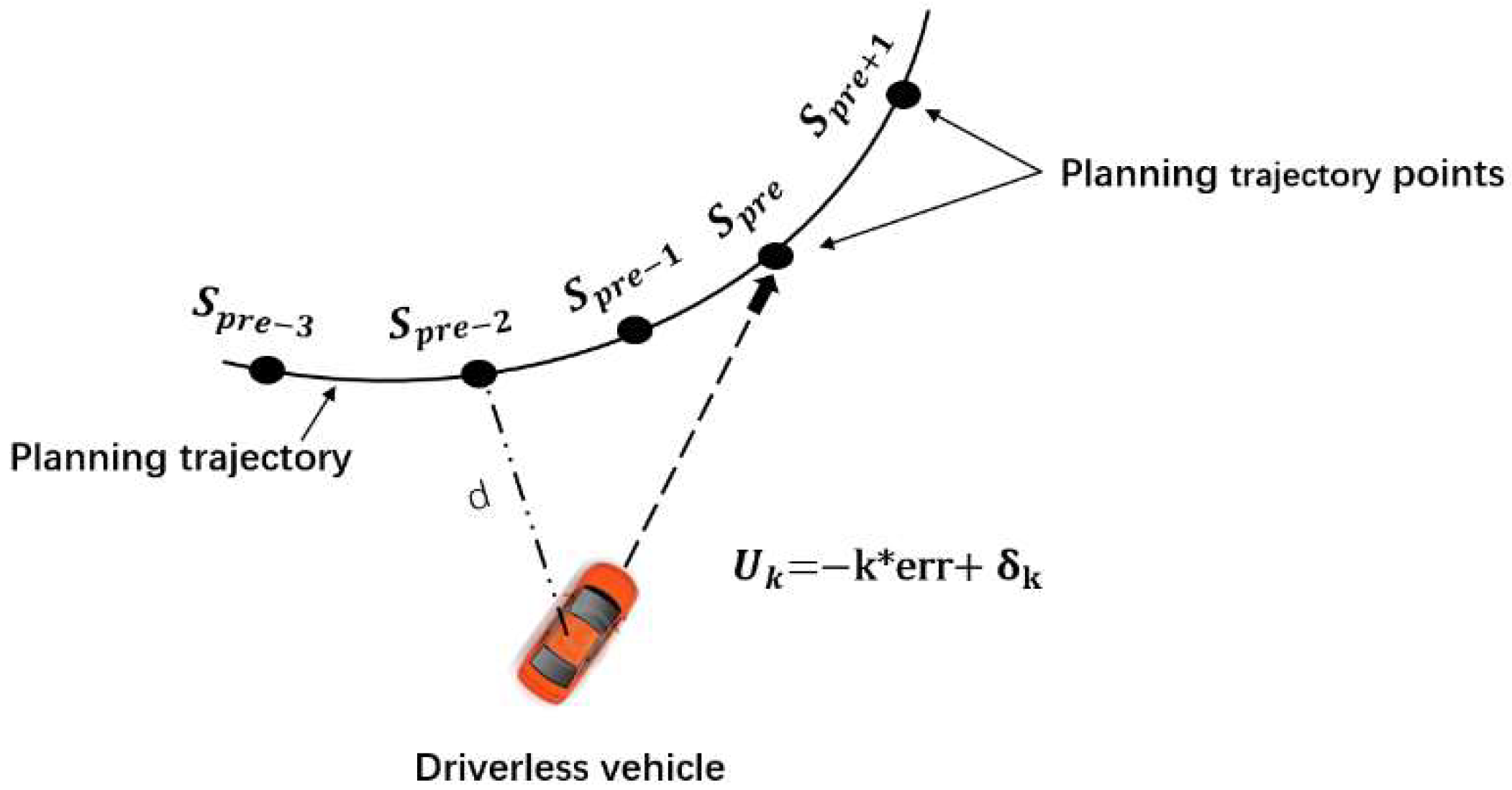
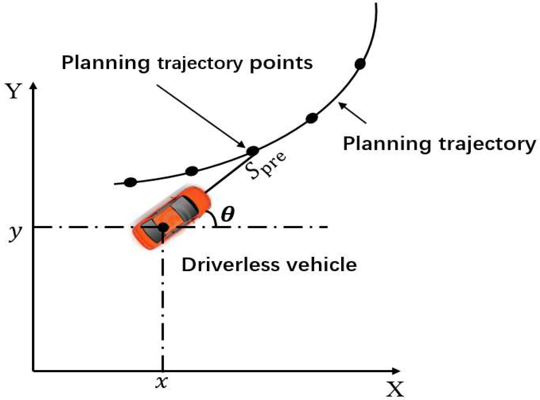
According to the test, it was found that if the intelligent driving vehicle runs at the position shown in Figure 3 and has a distance error from the planned path, and the planned path point can still be tracked at a certain time in the future when driving along the current position, the system will not generate a steady-state error at this time, the system cannot track point at the current time, and the vehicle can continue to drive along in the current state.
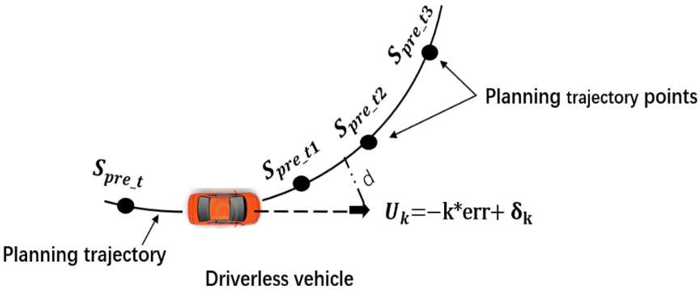
If the current position of the intelligent driving vehicle is already traveling on the planned path, as shown in Figure 4, the vehicle will continue to drive in the current state at the next moment until the vehicle deviates from the planned path. After the system determines that the vehicle has a steady-state error, the controller controls the vehicle movement. At this time, we need the vehicle to be able to predict the planned point for a period of time in the future, so that the vehicle can keep driving at the planned route point in real time.
According to the above possible problems, the system adds a predictive controller to predict the trajectory points in the future for a period of time, and the system determines it to control the front wheel angle of the vehicle in real time to effectively track the path, which can eliminate the lag of the control system and reduce the control system function consumption, and increase the system stability and comfort. The schematic diagram is shown in Figure 5.
The prediction time is set as . The coordinate position information of the predicted time point is (). Because , there are:
3.4. Establishment of Environmental Awareness System
Due to the diversity and complexity of the road environment and the weather environment, the intelligent driving vehicle tracking control will be greatly affected. In order to verify that the proposed control method is more in line with the actual road conditions, this paper takes into account the research on intelligent vehicle lateral control in the real road environment, collects road information in advance and processes data through an environment sensing system, and fits the path required for the tracking control below. Therefore, an environmental awareness system is established.
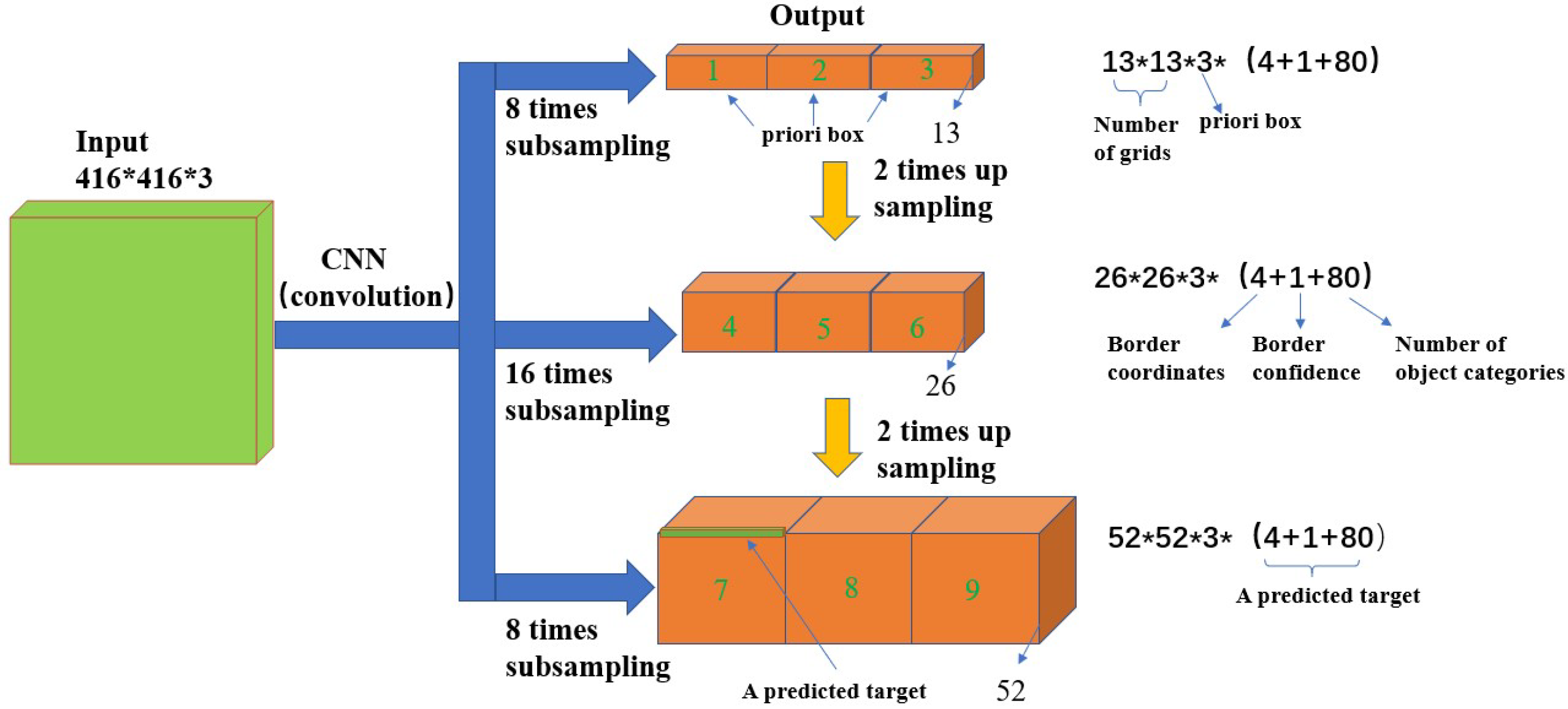
The central idea of the YOLOv3 algorithm used in the establishment of environmental awareness in this paper is to divide the picture into grids in equal proportion, use the grid to predict the rectangular box and contain the location, confidence and other information of the target, and finally to obtain the final prediction box through non-maximum suppression filtering [35]. A YOLOv3 detection algorithm belongs to the one stage algorithm, which has the advantages of a small amount of calculation and a fast response. Therefore, it is often used to detect vehicles and pedestrians in urban roads and has achieved good research results [36]. Yolov3 uses the pyramid-like method for reference to predict on three scales of different sizes, and then the network outputs the detection results of three different scales. Each detection result includes the coordinate position, category and confidence of vehicles and the coordinate position and confidence of pedestrians. In the prediction process, different scale feature maps predict targets of different sizes, and finally combine the prediction results of the three scales for non-maximum suppression algorithm processing [37]. The network structure principle is shown in Figure 6.
The YOLOv3 algorithm meets the requirements of real-time detection in recognition accuracy and detection rates under different environments and working conditions, and the average recognition rate is 28.4 f/s. The establishment of an environmental perception system collects the image information of vehicles and pedestrians in an urban road environment under different working conditions, verifies the recognition accuracy and rate of vehicles and pedestrians based on the YOLOv3 algorithm in the real urban road environment, and records vehicle and pedestrian videos under different working conditions to realize the recognition and detection of vehicles and pedestrians in the offline state. The pedestrian outputs the position coordinate information and fits the path equation that can avoid obstacles, so as to provide a path for the following path tracking control. So as to ensure that the path tracked by the set controller during the test is true, the road environment is more in line with the actual situation. The main aim of this paper is to propose a lateral control method with a feedforward + predictive LQR, and so the environmental perception part is not discussed in detail.
4. Simulation and Hardware in the Loop Test
In order to verify the feasibility of the designed lateral motion controller with feedforward + predictive LQR, first, Matlab/Simulink and CarSim software are used for joint simulation, and the control effect of the controller is tested under the simulation. Then, the hardware in the loop test is carried out to verify the effectiveness of the path tracking control algorithm and its adaptability to different road test conditions on the premise that the road information under different working conditions is collected in advance and the obstacle avoidance path has been planned. This is to verify whether the communication between the control module and other functional modules in the algorithm program is in real time, and whether the control module can quickly, accurately and stably realize the path tracking function according to the planned path according to the vehicle position and attitude information provided by the navigation system in real time.
4.1. Simulation Test and Analysis under Different Working Conditions
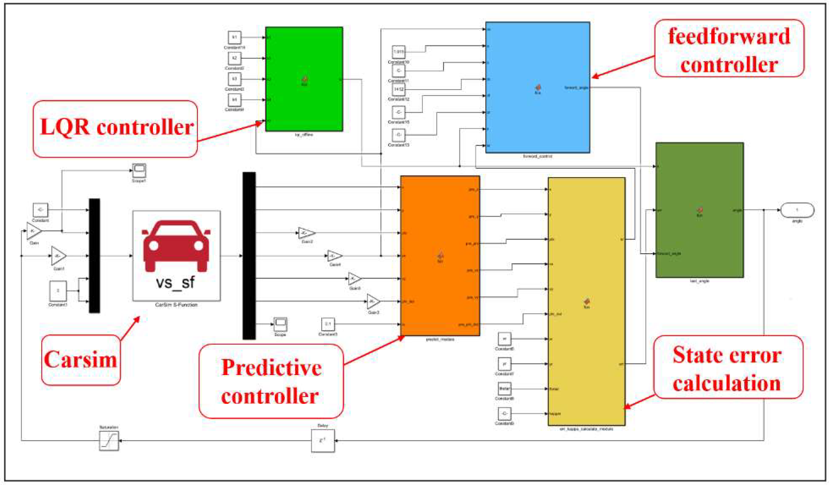
In order to better verify the control performance of the designer, the path tracking simulation test will be carried out under two road conditions collected in advance. The road environment in this paper is collected in a real environment. The road environment can include cement pavement, asphalt pavement, rain and snow pavement, etc., which can meet the requirements of vehicle testing in different road environments. The test conditions are urban roads, and the tire-road friction factor is shown in Table 1. The two working conditions are Roundabout (the speed is set at 50 km/h) and complex steering (the speed is set at 30 km/h). The optimal control rate solved by the Matlab/Simulink control model is used as the control input of CarSim for joint simulation verification. In order to better compare the control effect of feedforward + predictive LQR, the simulation results are compared with a feedforward + LQR control method, LQR controller without feedforward control and an MPC control method. The simulation model of the lateral control system is built as shown in Figure 7.
In the simulation, CarSim selects the class C passenger car model, and the vehicle parameter settings are shown in Table 1.
4.1.1. Simulation Test of the Roundabout Working Condition
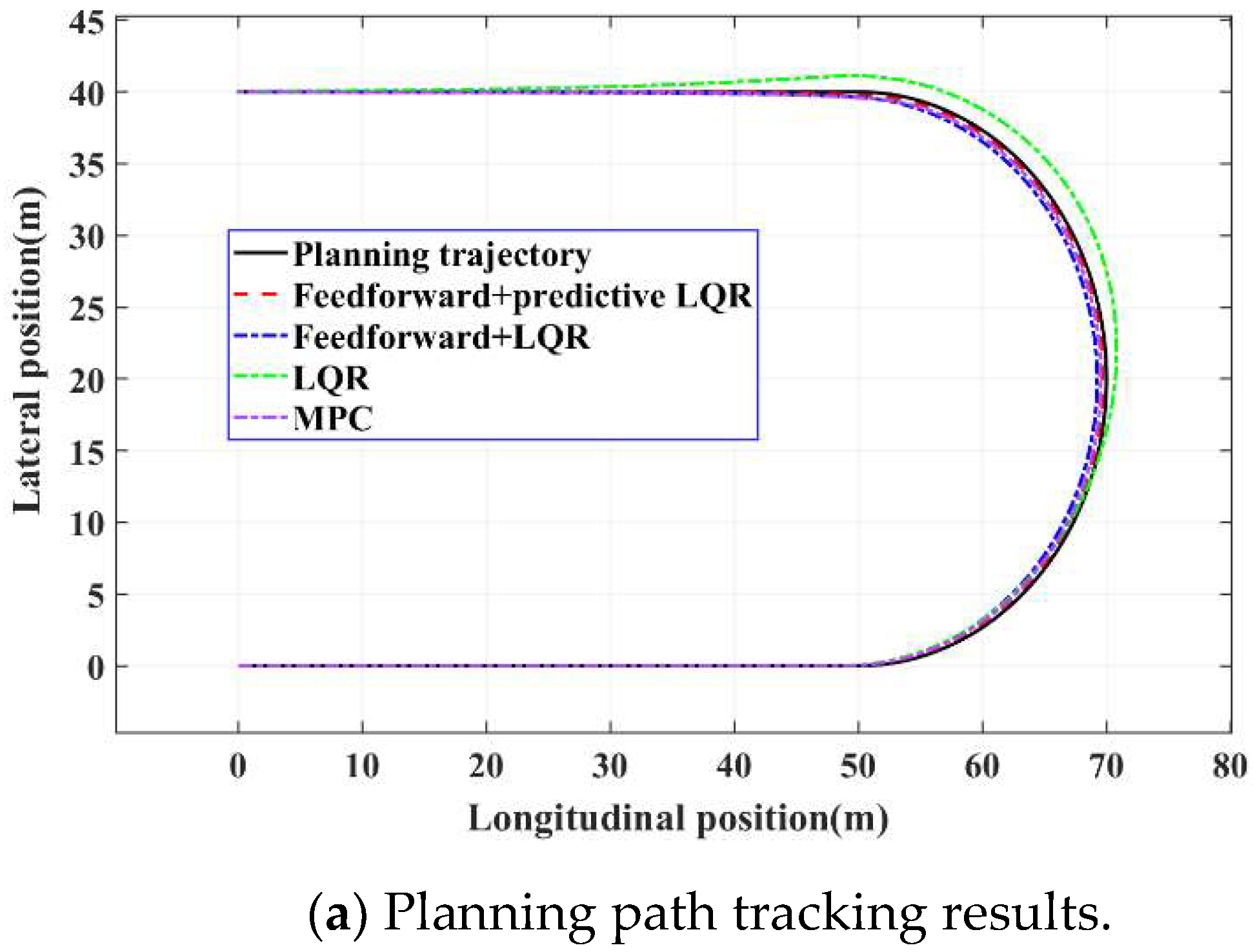
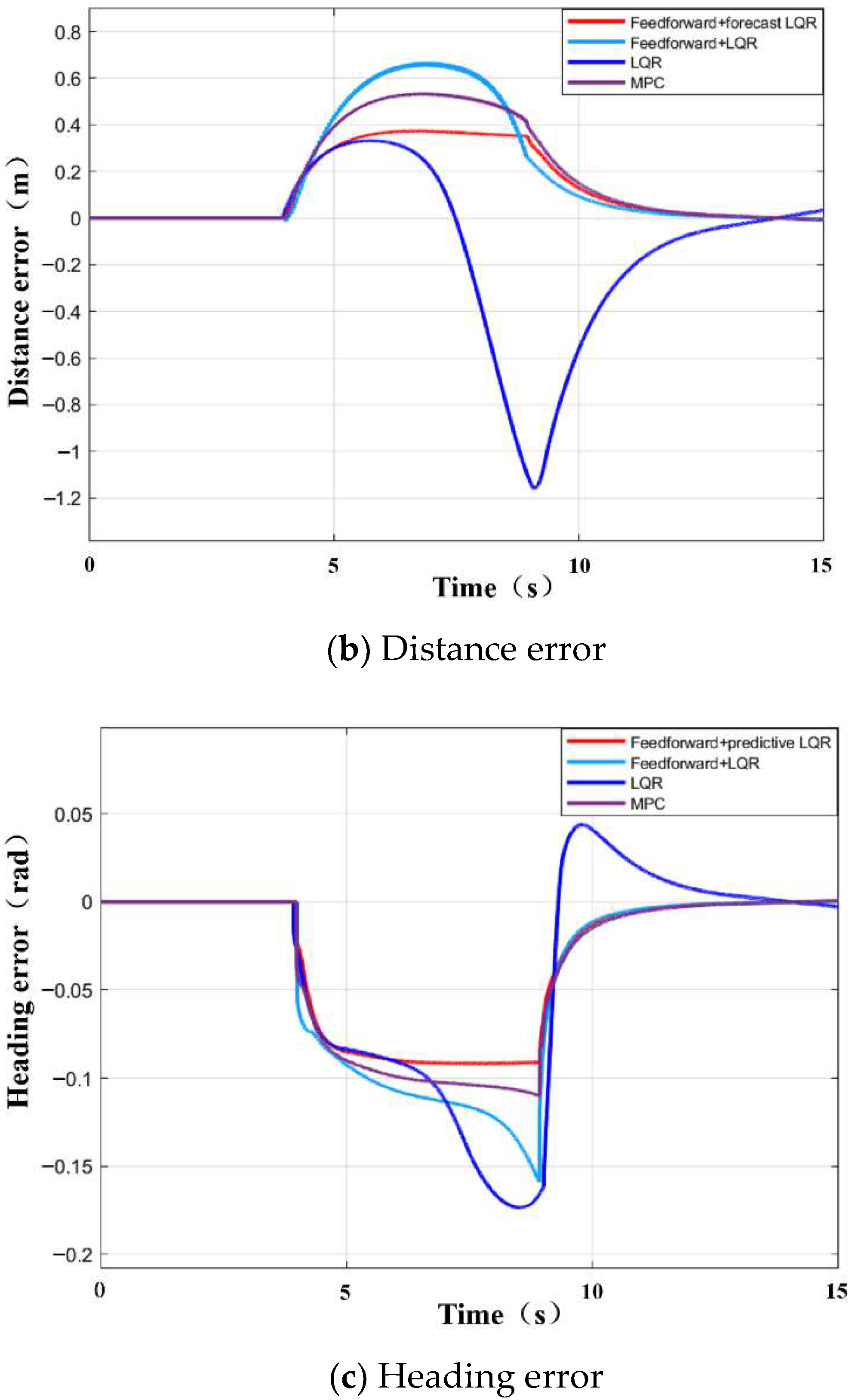
Figure 8a shows the path tracking comparison results of four control methods under the roundabout condition. It can be seen from the diagram that all four methods can effectively track the target path, and the vehicle with feedforward + predictive LQR control has the best overall path tracking effect. Figure 8b,c describe the distance error and course error of four controllers under this operating condition. It can be seen that all four control methods can track the straight line path well in the starting motion stage. The distance error between tracking and target path can be controlled within 0.1 m and the heading error within 0.01 rad. However, when the vehicle is steering, the adjustment of control quantity is obviously different between the four control methods, in which the maximum distance error and the maximum course error of the controller with feedforward + predictive LQR are 0.37 m and 0.08 rad, respectively. The control effect of the MPC controller is relatively poor, with the maximum distance error exceeding 0.5 m and the maximum course error exceeding 0.12 rad. The distance error of the LQR controller with feedforward is poor when tracking bends, and the maximum value exceeds 0.65 m and the maximum value of heading error exceeds 0.15 rad. The LQR controller has the worst control effect between the four, with the maximum distance error exceeding 1 m and the maximum course error exceeding 0.17 rad. Through a comparative analysis, the maximum distance error control accuracy of the controller with feedforward + predictive LQR is 43.1% higher than that with feedforward + LQR controller, 67.8% higher than that of LQR controller and 28.8% higher than that of MPC control method. The accuracy of the maximum course error control is 46.7% higher than that of the LQR controller with a feedforward + LQR controller, 52.9% higher than that of LQR controller and 21.2% higher than that of the MPC control method.
4.1.2. Simulation Test of Complex Steering Conditions
In order to verify the stability of the controller under complex working conditions, the experiments of linear tracking and continuous lane changing under complex roads are carried out.
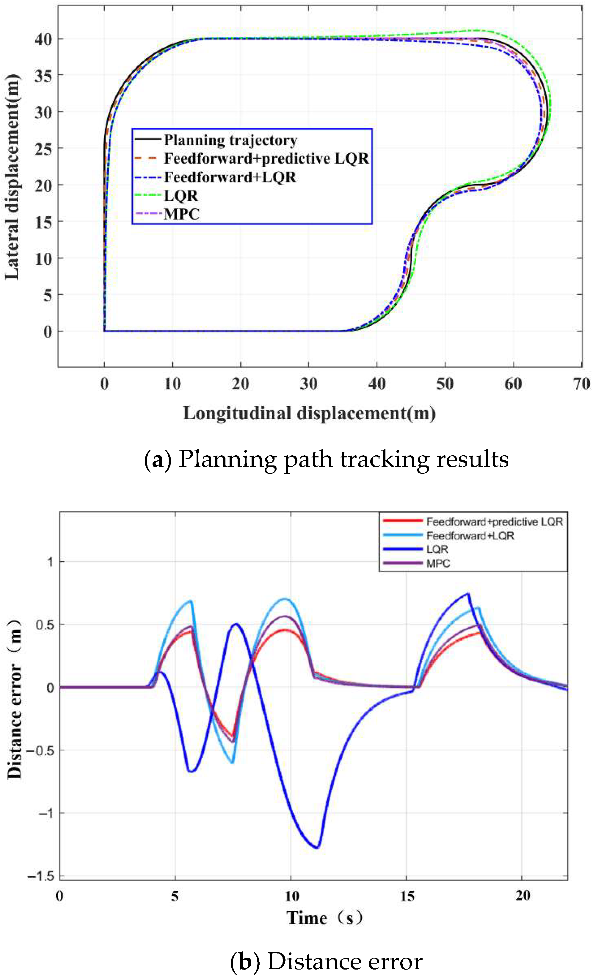
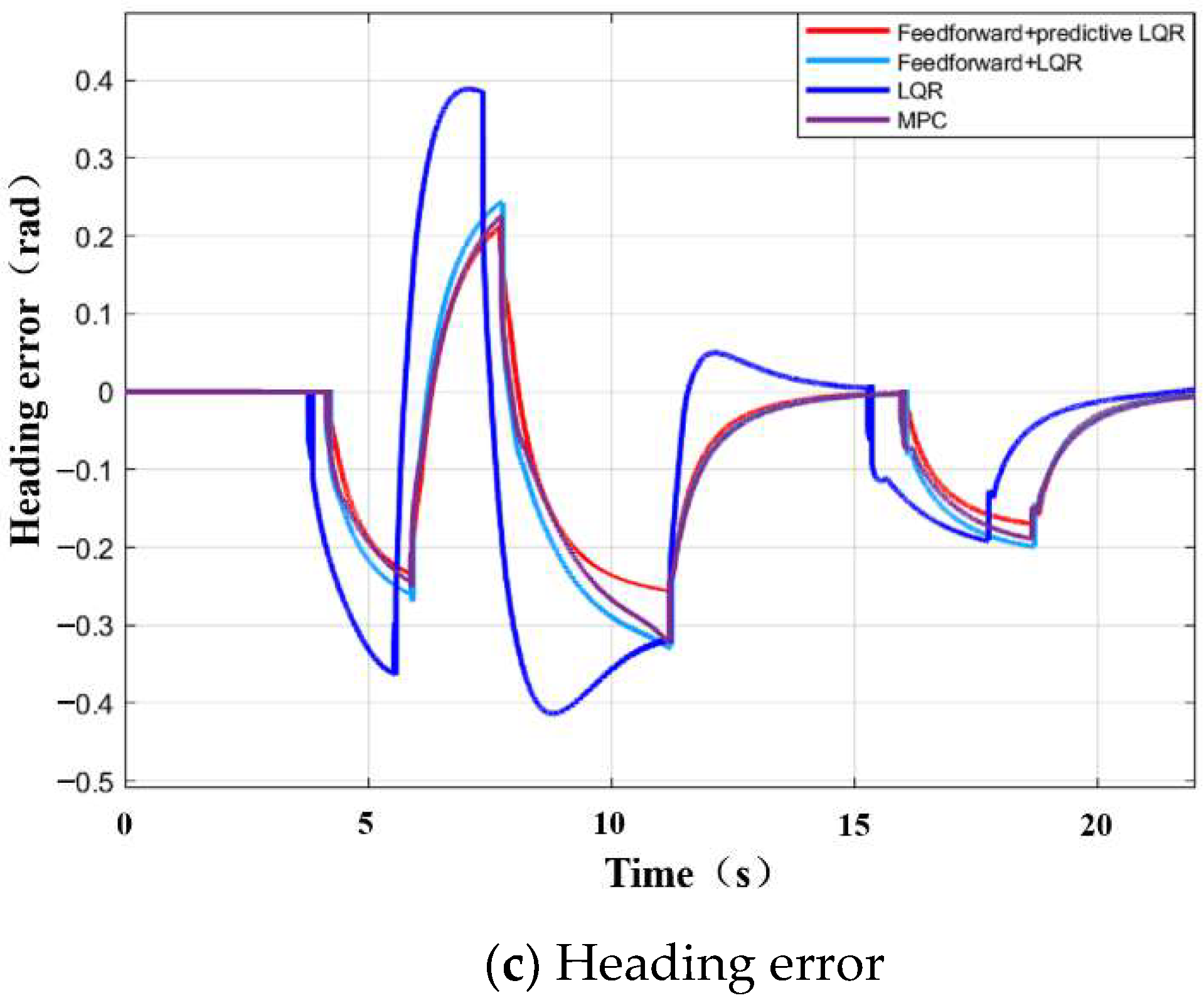
Figure 9a shows the path tracking comparison results of four control methods under complex road conditions. The test results show that the controller with feedforward + predictive LQR can track the target path well. Observe that Figure 9b,c, with feedforward + predictive LQR controller, still keep a good control effect when tracking a straight line with a target path under this operating condition. The maximum distance error is less than 0.1 m and the maximum course error is less than 0.01 rad. The maximum distance error of the tracking bend is controlled in the range of 0.45 m and the maximum course error is controlled in the range of 0.25 rad, which achieves a good path tracking accuracy and control effect. The control effect of the MPC controller is slightly lower than that of the former, with the maximum distance error within 0.55 m and the maximum course error within 0.32 rad. The control effect of the LQR controller, with feedforward is poor. The maximum distance error of the tracking bend is within 0.7 m and the maximum course error is within 0.36 rad. Although the LQR controller can control the distance error between straight line tracking and target path to a small value, the maximum distance error exceeds 1.2 m and the maximum course error exceeds 0.42 rad when tracking bends. Through a comparative analysis, the maximum distance error control accuracy of the controller with feedforward + predictive LQR is 35.7%, 62.5% and 21.2% higher than that with feedforward + LQR controller and an MPC control method. The accuracy of a maximum course error control is 30.5% higher than that of feedforward + LQR controller, 40.5% higher than that of LQR controller and 18.8% higher than that of the MPC control method.
Through a comparative analysis, it can be seen that the LQR controller has obvious hysteresis, certain steady-state errors and an obvious overshoot in the control of distance error and heading error under this working condition. The traditional MPC control method has a limited ability to deal with system uncertainty. When the system model is inaccurate, or there is an external disturbance in the external road environment, it is often difficult to achieve the established control objectives.
4.2. Hardware in the Loop Test and Analysis
4.2.1. Introduction of Hardware in the Loop Test Platform
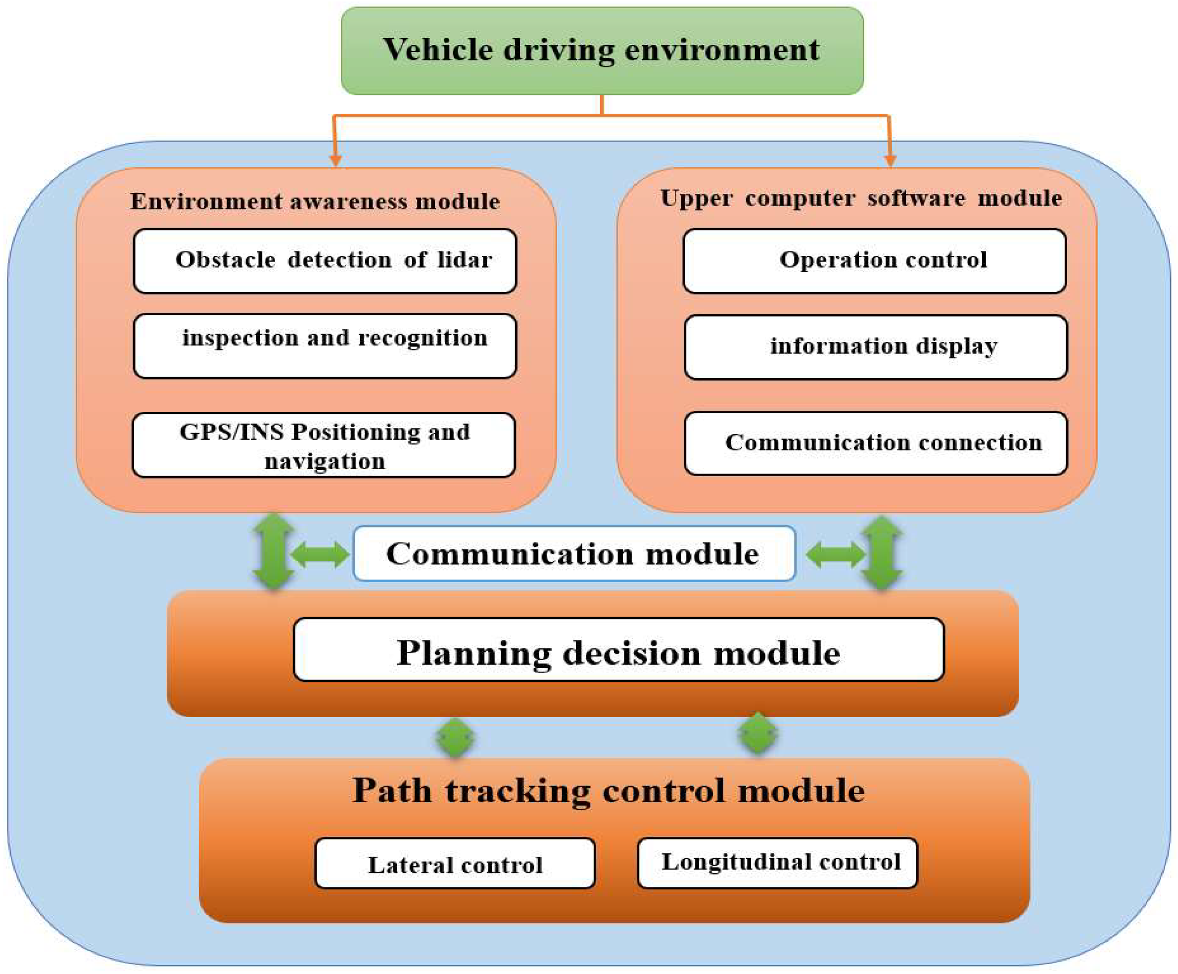
The hardware-in-the-loop (HIL) test platform software module design for intelligent vehicles is mainly composed of three parts: an environment awareness module composed of sensors, a host computer interface display module, and a control module. The software function introduction is shown in Figure 10. The environment awareness module monitors the surrounding environment information of the vehicle through the environment perception sensor, realizes the information collection and data processing of the intelligent driving vehicle sensor, and fits the path equation; the display module realizes the real-time display and storage of relevant information; the control module performs path tracking control, which can realize the lateral and longitudinal control of the vehicle. This paper only studies the lateral control of intelligent driving, and the longitudinal vehicle speed defaults to a constant value.
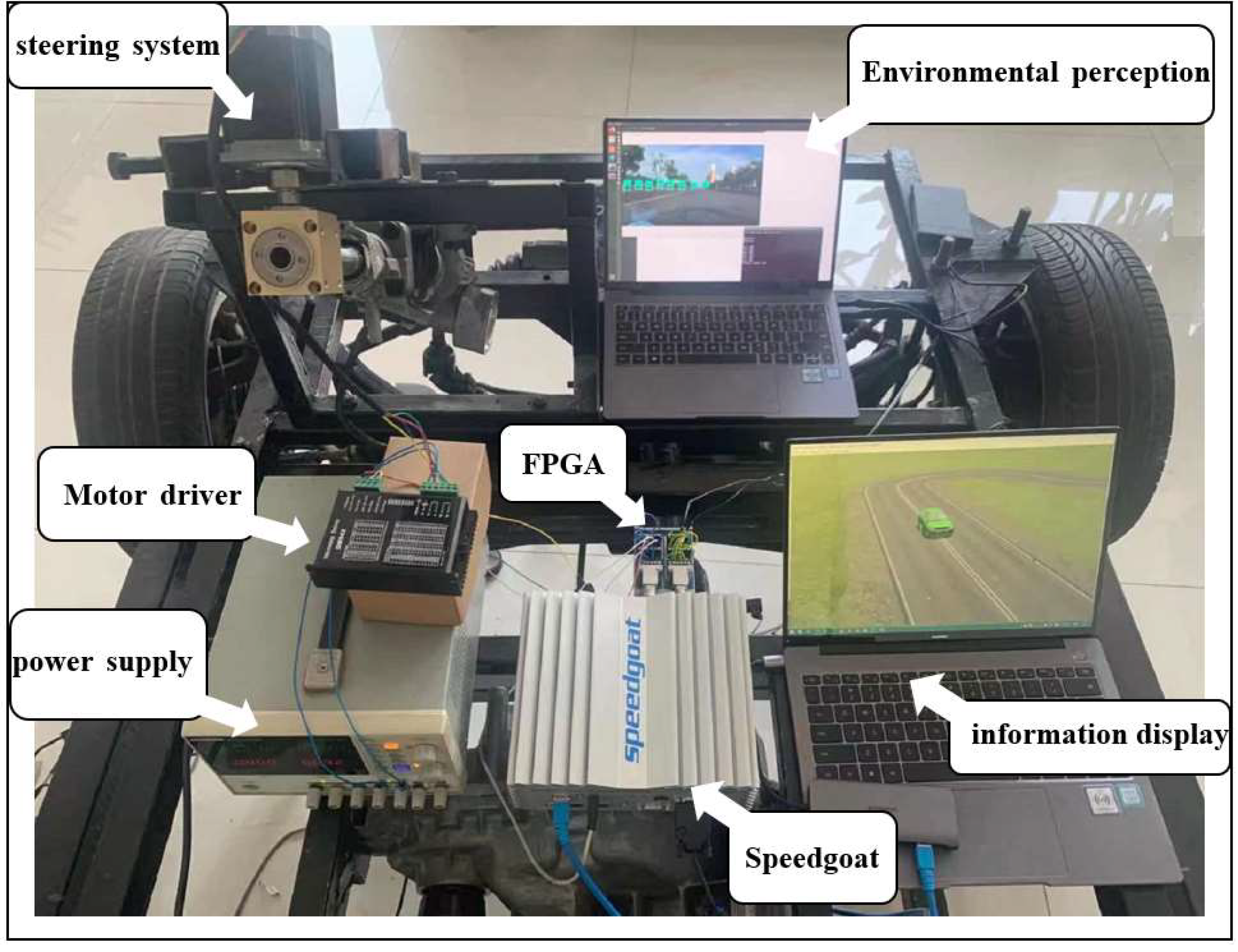
The HIL test platform is shown in Figure 11. The designed lateral controller is embedded into the test platform, and the commercial vehicle software CarSim is used to replace the real vehicle control. The actuator and control mechanism are actual mechanisms. The test bench includes a computer embedded in a road environment model and a vehicle dynamics model, closed-loop automatic steering system, real-time controller Speedgoat equipment and an FPGA-IO397 board.
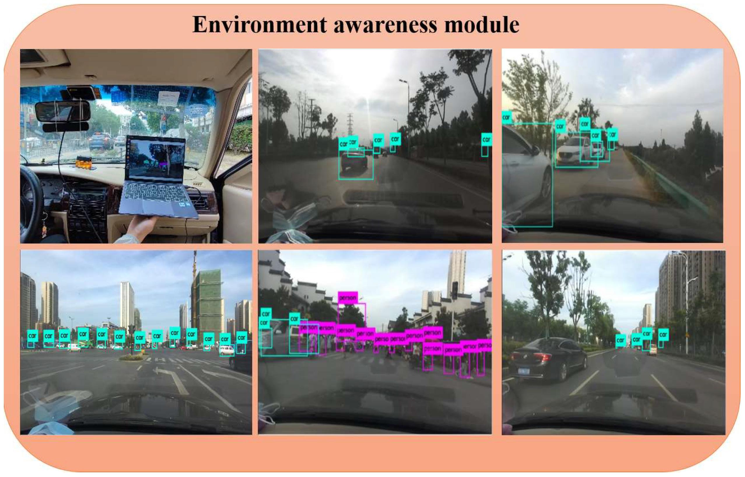
The environment perception module uses the yolov3 algorithm and takes the Linux system as the platform to collect the image information of vehicles and pedestrians in the urban road environment under different working conditions, and mixes it with the pictures of vehicles and pedestrians in the KITTI data set to form a self-made data set. The database model is trained by the YOLOv3 algorithm to verify the accuracy of YOLOv3 algorithm in vehicle and pedestrian recognition. In the real urban road environment, the accuracy and speed of YOLOv3’s recognition of vehicles and pedestrians are tested in real time, and the videos of vehicles and pedestrians under different working conditions are recorded to realize the recognition and detection of vehicles and pedestrians in an offline state, to output the position coordinate information, and to fit the path equation that can avoid obstacles [38]. Thus, the road environment running during the vehicle test can be sent to the control module in real time, ensuring that the vehicle is running in real road conditions in real time, and increasing the feasibility of the control method. The effect of real-time detection and recognition of vehicles and pedestrians on urban roads is shown in Figure 12.
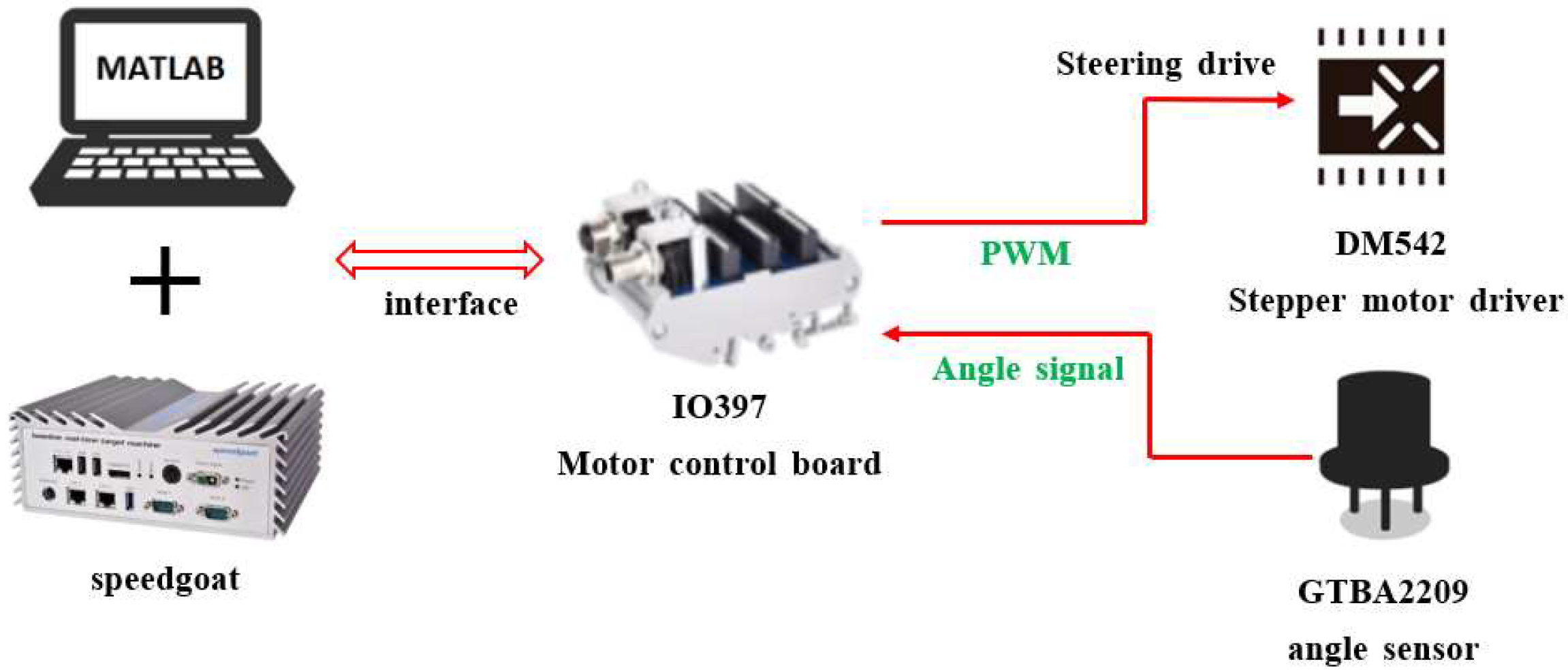
After the control module receives the planning path equation, the vehicle jointly simulated by Matlab/Simulink and CarSim starts to move according to the planned path, and the Speedgoat is connected through the communication interface. The controller sends the motion control command to the FPGA-IO397 board, which sends a PWM pulse signal to the signal control port of the DM542 stepper motor driver, and the steering motor gradually controls the vehicle steering through the vehicle automatic steering system. At the same time, the angle sensor GTBA2209 installed on the front wheel of the vehicle transmits the real-time collected steering angle back to the fpag-io397 board for accurate steering. The control flow chart is shown in Figure 13.
4.2.2. Analysis of Hardware in the Loop Test Results
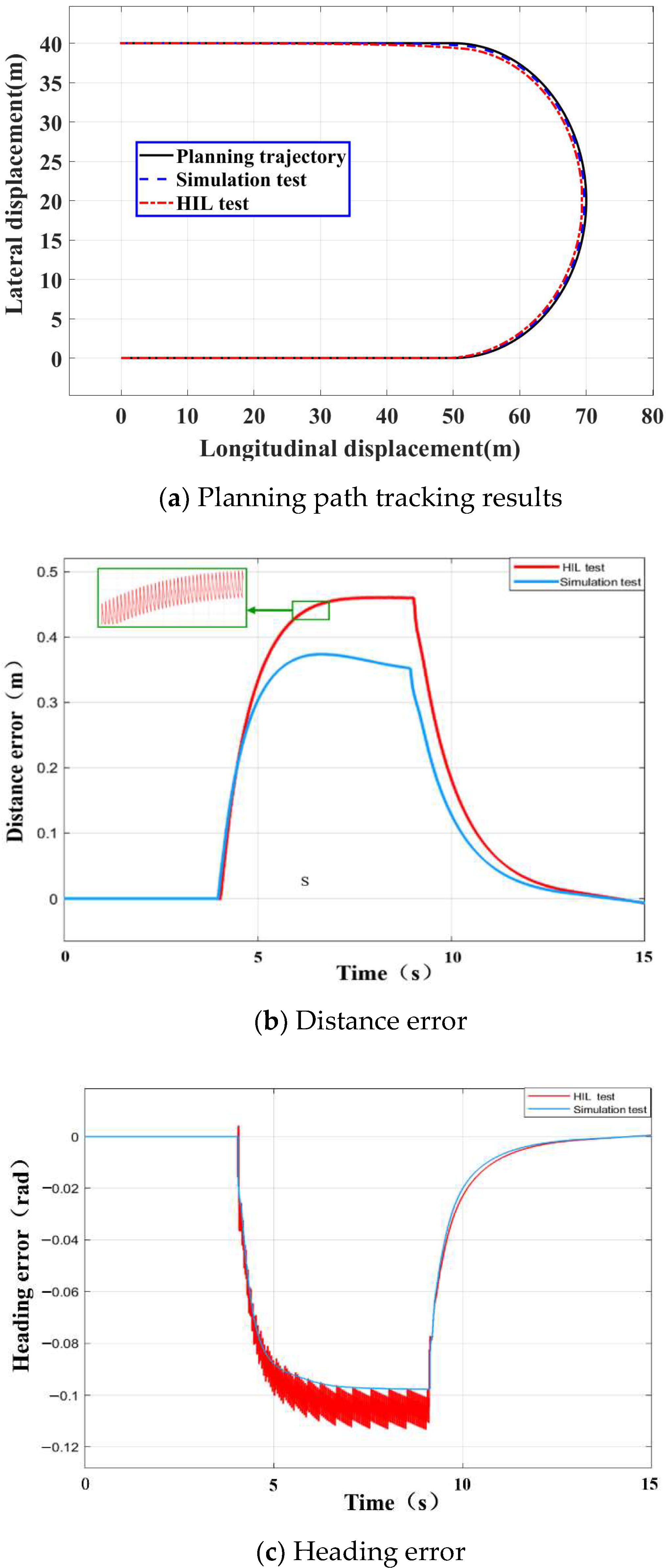
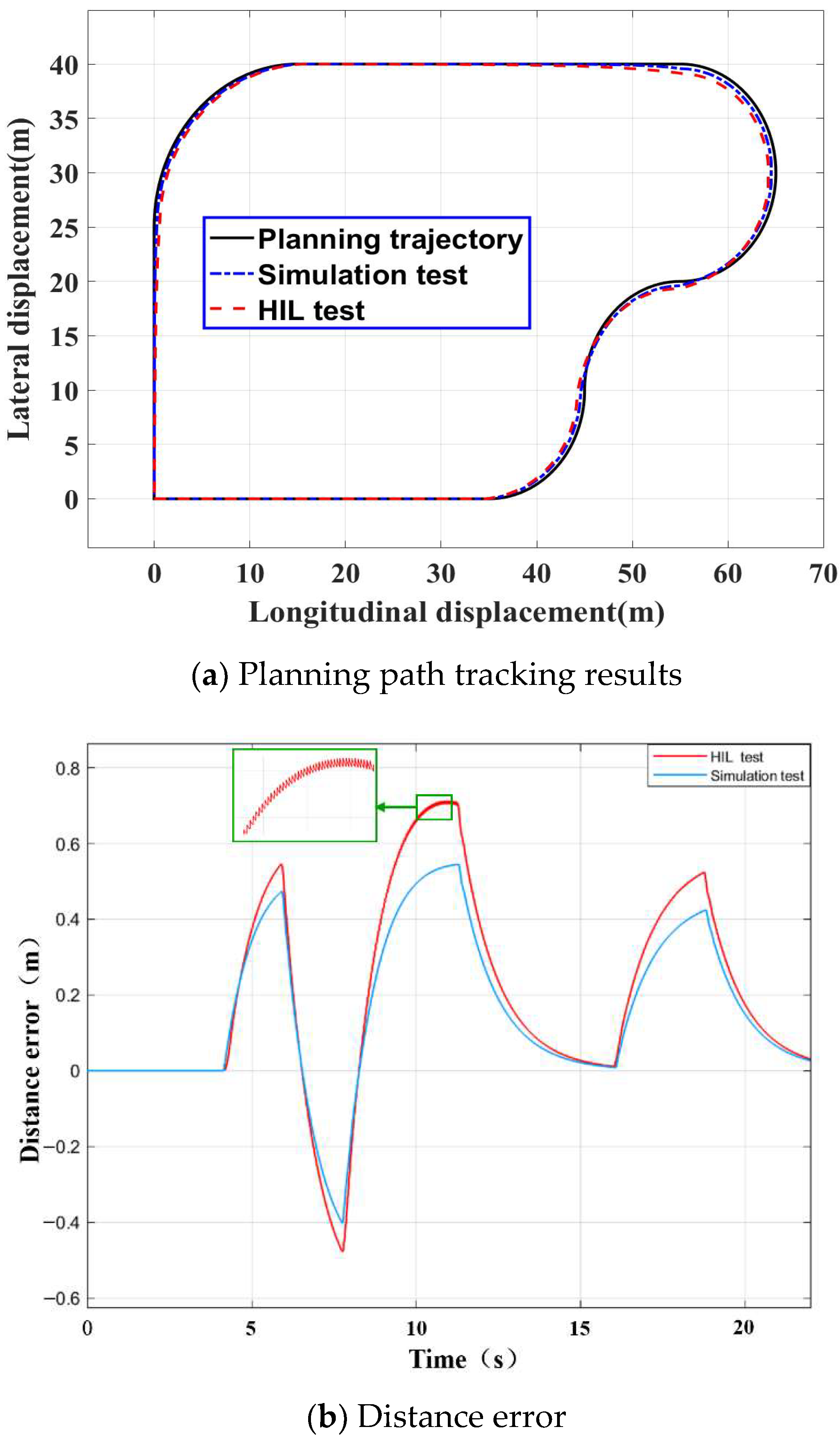
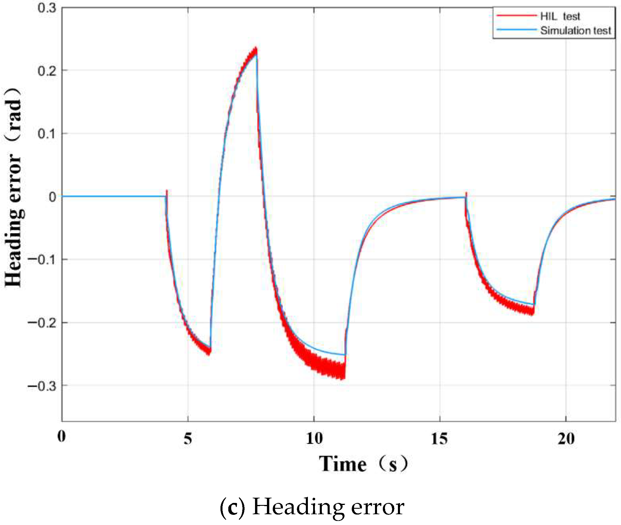
Figure 14a shows the comparison between simulation test and hardware path tracking under the condition of loop island. It can be seen from the Figure that the lateral controller designed in this paper can control the vehicle to track the desired path under the working condition with a high precision, and the tracking deviation is within the allowable range. Figure 14b,c show the comparison of distance error and heading error between simulation test and hardware under the condition of loop test under the condition of an island. It can be seen from the Figure that the distance error between the linear tracking and the target path is less than 0.1 m under the condition of the island, and the distance error of the tracking curve is less than 0.45 m. The error, of course, is basically consistent. Because of the noise caused by the interference of sensor data, the distance error and heading error are fluctuating. However, the control system can still track according to the desired path, and achieved a better control effect, which proves the feasibility of the algorithm in the loop test.
Figure 15a shows the comparison effect of path tracking between the simulation test and hardware in the loop test under complex steering conditions. Figure 15b,c show the comparison of distance error and heading error between different simulation test and hardware in the loop test under complex steering conditions. It can be seen from the Figure that the vehicle can still track the target path well in a complex road environment. By observing Figure 15b,c, the distance error of the vehicle in the hardware in the loop test on the straight-line tracking section can be controlled within 0.1 m, and the heading error can be controlled within 0.01 rad. However, in the tracking curve section, the distance error and heading error of the vehicle will increase, and there will be an overshoot to a certain extent, so that the vehicle body will drive out of the predetermined reference path. The maximum distance error is 0.65 m and the maximum heading error is 0.28 rad. However, it can quickly return to the established path after completely leaving the curve and entering the straight section and can realize path tracking within the acceptable steady-state error range.
5. Conclusions
Research into the lateral motion control in the intelligent driving structure system was carried out. Firstly, based on the vehicle dynamic tracking error model, combined with three control methods, an intelligent vehicle path tracking transverse controller was designed and the environment perception system based on the YOLOv3 algorithm was designed. Then, the road information is collected and processed by the environmental awareness system, and the path required for tracking control is fitted. Combined with the hardware in the loop test platform of the intelligent vehicle automatic steering system, the actual control effect of feedforward + predictive LQR controller is verified under roundabout conditions and complex steering conditions. Finally, the simulation and hardware test results show that the designed control can effectively realize the real-time vehicle path tracking in the actual implementation, and improve the control effect and control accuracy of the vehicle. This paper considers the design of an intelligent driving vehicle lateral control system, but does not consider the influence of the change and interference of longitudinal control. The next step will consider the design of combining a longitudinal control to establish a more perfect intelligent driving tracking control system.
Author Contributions
Conceptualization, T.Y.; methodology, T.Y.; software, T.Y.; validation, Z.B.; formal analysis, Z.L.; investigation, Z.B.; resources, Z.L.; data curation, T.Y.; writing—original draftpreparation, T.Y.; writing—review and editing, L.C. and T.Y.; visualization, N.F.; supervision, N.F.; project administration, L.C.; funding acquisition, L.C. All authors have read and agreed to the published version of the manuscript.
Funding
This study was funded by Anhui Natural Science Foundation Project (Grant No. 1908085ME174).
Institutional Review Board Statement
Not applicable.
Informed Consent Statement
Not applicable.
Data Availability Statement
The data used in this study is self-test and self-collection. Becausethe control method designed in this paper is still being further improved, Data cannot be sharedat present.
Conflicts of Interest
The authors declare no conflict of interest.
References
- Chen, L.; Li, Z.; Yang, J.; Song, Y. Lateral Stability Control of Four-Wheel-Drive Electric Vehicle Based on Coordinated Control of Torque Distribution and ESP Differential Braking. Actuators 2021, 10, 135. [Google Scholar] [CrossRef]
- Cao, K.; Li, Z.; Gu, Y.; Zhang, L.; Chen, L. The control design of transverse interconnected electronic control air suspension based on seeker optimization algorithm. Proc. Inst. Mech. Eng. Part D J. Automob. Eng. 2021, 235, 2200–2211. [Google Scholar] [CrossRef]
- Ribeiro, A.M.; Fioravanti, A.R.; Moutinho, A.; de Paiva, E.C. Nonlinear state-feedback design for vehicle lateral control using sum-of-squares programming. Veh. Syst. Dyn. 2020, 1844905. [Google Scholar] [CrossRef]
- Ando, T.; Kugimiya, W.; Hashimoto, T.; Momiyama, F.; Aoki, K.; Nakano, K. Lateral Control in Precision Docking Using RTK-GNSS/INS and LiDAR for Localization. IEEE Trans. Intell. Veh. 2020, 6, 78–87. [Google Scholar] [CrossRef]
- Lu, X.; Xing, Y.; Guirong, Z. Overview of the development status of motion control of unmanned vehicles. J. Mech. Eng. 2020, 56, 17. [Google Scholar]
- Choi, W.Y.; Kim, D.J.; Kang, C.M.; Lee, S.; Chung, C.C. Autonomous Vehicle Lateral Maneuvering by Approximate Explicit Predictive Control. In Proceedings of the 2018 Annual American Control Conference (ACC), Milwaukee, WI, USA, 27–29 June 2018; pp. 4739–4744. [Google Scholar] [CrossRef]
- Guo, N.; Zhang, X.; Zou, Y.; Lenzo, B.; Zhang, T. A Computationally Efficient Path-Following Control Strategy of Autonomous Electric Vehicles With Yaw Motion Stabilization. IEEE Trans. Transp. Electrif. 2020, 6, 728–739. [Google Scholar] [CrossRef]
- Lin, F.; Zhang, Y.; Zhao, Y.; Zhao, Y.; Yin, G.; Zhang, H.; Wang, K. Trajectory Tracking of Autonomous Vehicle with the Fusion of DYC and Longitudinal–Lateral Control. Chin. J. Mech. Eng. 2019, 32, 1–16. [Google Scholar] [CrossRef]
- Nguyen, A.T.; Rath, J.J.; Guerra, T.M.; Rath, J.; Zhang, H.; Palhares, R. Robust Set-Invariance Based Fuzzy Output Tracking Control for Vehicle Autonomous Driving Under Uncertain Lateral Forces and Steering Constraints. IEEE Trans. Intell. Transp. Syst. 2020, 1–7. [Google Scholar] [CrossRef]
- Chen, C.; Lv, J.; Song, G.; Liu, H. Adaptive fuzzy sliding mode control algorithm based on input-output linearization for vehicle’s lateral control. In Proceedings of the 2016 IEEE Chinese Guidance, Navigation and Control Conference (CGNCC), Nanjing, China, 12–14 August 2016; IEEE: Piscataway Township, NJ, USA, 2016. [Google Scholar]
- Brown, M.; Funke, J.; Erlien, S.; Gerdes, J.C. Safe driving envelopes for path tracking in autonomous vehicles ScienceDirect. Control. Eng. Pract. 2017, 61, 307–316. [Google Scholar] [CrossRef]
- Zhang, W. A robust lateral tracking control strategy for autonomous driving vehicles. Mech. Syst. Signal Process. 2021, 150, 107238. [Google Scholar] [CrossRef]
- Bao, C.; Feng, J. Model predictive control of steering torque in shared driving of autonomous vehicles. Sci. Prog. 2020, 103, 1–22. [Google Scholar] [CrossRef]
- Goodarzi, A.; Sabooteh, A.; Esmailzadeh, E. Automatic path control based on integrated steering and external yaw-moment control. Proc. Inst. Mech. Eng. Part K J. Multi-Body Dyn. 2008, 222, 189–200. [Google Scholar] [CrossRef]
- Cui, Q.; Ding, R.; Wei, C.; Zhou, B. Path-tracking and lateral stabilisation for autonomous vehicles by using the steering angle envelope. Veh. Syst. Dyn. 2020, 1–25. [Google Scholar] [CrossRef]
- Li, P.; Nguyen, A.T.; Du, H.; Wang, Y.; Zhang, H. Polytopic LPV Approaches for Intelligent Automotive Systems: State of the Art and Future Challenges. Mech. Syst. Signal. Process. 2021, 161, 107931. [Google Scholar] [CrossRef]
- Guo, N.; Lenzo, B.; Zhang, X.; Zou, Y.; Zhai, R.; Zhang, T. A Real-time Nonlinear Model Predictive Controller for Yaw Motion Optimization of Distributed Drive Electric Vehicles. IEEE Trans. Veh. Technol. 2020, 69, 4935–4946. [Google Scholar] [CrossRef] [Green Version]
- Benariba, H.; Boumediene, A. Lateral Sliding Mode Control of an Electric Vehicle. In Proceedings of the 2018 6th International Conference on Control Engineering & Information Technology (CEIT), Istanbul, Turkey, 25–27 October 2018. [Google Scholar]
- Wang, Z.; Wang, M.; Zhang, Y.; Guan, T.; Song, X.; Liu, J.; Zhen, Y.; Zhang, D. Driverless simulation of path tracking based on PID control. IOP Conf. Ser. Mater. Sci. Eng. 2020, 892, 012050. [Google Scholar] [CrossRef]
- Qian, X.; Arnaud, D.; Moutarde, F. A Hierarchical Model Predictive Control Framework for On-road Formation Control of Autonomous Vehicles. In Proceedings of the 2016 IEEE Intelligent Vehicles Symposium (IV), Gothenburg, Sweden, 19–22 June 2016; IEEE: Piscataway Township, NJ, USA, 2016; pp. 376–381. [Google Scholar]
- Tang, F.; Li, C. Intelligent vehicle lateral tracking control based on multiple model prediction. AIP Adv. 2020, 10, 075107. [Google Scholar] [CrossRef]
- Li, Z.; Wang, P.; Liu, H.; Hu, Y.; Chen, H. Coordinated longitudinal and lateral vehicle stability control based on the combined-slip tire model in the MPC framework. Mech. Syst. Signal Process. 2021, 161, 107947. [Google Scholar] [CrossRef]
- Olalla, C.; Leyva, R.; Aroudi, A.E.; Queinnec, I. Robust LQR Control for PWM Converters: An LMI Approach. IEEE Trans. Ind. Electron. 2009, 56, 2548–2558. [Google Scholar] [CrossRef]
- Sharp, R.S.; Peng, H. Vehicle dynamics applications of optimal control theory: Vehicle System Dynamics. Veh. Syst. Dyn. 2011, 49, 1073–1111. [Google Scholar] [CrossRef]
- Snider, J.M. Automatic steering methods for autonomous automobile path tracking. In Robotics Institute; CMURITR-09-08; Carnegie Mellon University: Pittsburgh, PA, USA, 2009. [Google Scholar]
- Kapania, N.R.; Gerdes, J.C. Design of a feedback-feedforward steering controller for accurate path tracking and stability at the limits of handling. Veh. Syst. Dyn. 2015, 53, 1687–1704. [Google Scholar] [CrossRef] [Green Version]
- Xu, S.; Peng, H. Design, Analysis, and Experiments of Preview Path Tracking Control for Autonomous Vehicles. IEEE Trans. Intell. Transp. Syst. 2019, 21, 48–58. [Google Scholar] [CrossRef]
- Zhen, Z.A.; Xi, A.; Tao, Y.A.; Gu, Y.; Wang, W.; Chen, L. Multi-objective optimization of lubricant volume in an ELSD considering thermal effects. Int. J. Therm. Sci. 2021, 164, 106884. [Google Scholar]
- Cheng, S.; Li, L.; Guo, H.Q.; Chen, Z.-G.; Song, P. Longitudinal Collision Avoidance and Lateral Stability Adaptive Control System Based on MPC of Autonomous Vehicles. IEEE Trans. Intell. Transp. Syst. 2019, 21, 2376–2385. [Google Scholar] [CrossRef]
- Zhang, J.; Wang, H.; Zheng, J.; Cao, Z.; Man, Z.; Yu, M.; Chen, L. Adaptive Sliding Mode-based Lateral Stability Control of Steer-by-Wire Vehicles with Experimental Validations. IEEE Trans. Veh. Technol. 2020, 69, 9589–9600. [Google Scholar] [CrossRef]
- Katebi, J.; Shoaei-Parchin, M.; Shariati, M.; Trung, N.T.; Khorami, M. Developed comparative analysis of metaheuristic optimization algorithms for optimal active control of structures. Eng. Comput. 2020, 36, 1539–1558. [Google Scholar] [CrossRef]
- Zhang, H.; Lewis, L.; Qu, Z. Lyapunov, Adaptive, and Optimal Design Techniques for Cooperative Systems on Directed Communication Graphs. IEEE Trans. Ind. Electron. 2012, 59, 3026–3041. [Google Scholar] [CrossRef]
- Xu, S.; Peng, H.; Song, Z.; Chen, K.; Tang, Y. Accurate and Smooth Speed Control for an Autonomous Vehicle. In Proceedings of the 2018 IEEE Intelligent Vehicles Symposium (IV), Changshu, China, 26–30 June 2018; IEEE: Piscataway Township, NJ, USA, 2018. [Google Scholar]
- Bencloucif, A.M.; Nguyen, A.T.; Sentouh, C.; Popieul, J. Cooperative Trajectory Planning for Haptic Shared Control between Driver and Automation in Highway Driving. IEEE Trans. Ind. Electron. 2019, 66, 9846–9857. [Google Scholar] [CrossRef]
- Redmon, J.; Divvala, S.; Girshick, R.; Farhadi, A. You Only Look Once: Unified, Real-Time Object Detection. In Proceedings of the IEEE Conference on Computer Vision and Pattern Recognition (CVPR), Las Vegas, NV, USA, 27–30 June 2016. [Google Scholar]
- Redmon, J.; Farhadi, A. YOLOv3: An Incremental Improvement. arXiv 2018, arXiv:1804.02767. [Google Scholar]
- Miao, F.; Tian, Y.; Jin, L. Vehicle Direction Detection Based on YOLOv3. In Proceedings of the 2019 11th International Conference on Intelligent Human-Machine Systems and Cybernetics (IHMSC), Hangzhou, China, 24–25 August 2019; pp. 268–271. [Google Scholar] [CrossRef]
- Gu, Y.; Li, Z.; Zhang, Z.; Li, J.; Chen, L. Path Tracking Control of Field Information-Collecting Robot Based on Improved Convolutional Neural Network Algorithm. Sensors 2020, 20, 797. [Google Scholar] [CrossRef] [Green Version]
Figure 1.
Vehicle dynamics and tracking error model.

Figure 2.
Lateral control system design.

Figure 3.
The current position of the vehicle is not at the same point as the planned position.

Figure 4.
The current position of the vehicle is at the same point as the planned position.

Figure 5.
Schematic diagram of the predictive control model.

Figure 6.
Schematic diagram of the yolov3 network structure.

Figure 7.
Establishment of the MATLAB/CarSim simulation model.

Figure 8.
Simulation test results of roundabout conditions.


Figure 9.
Test results under complex steering conditions.


Figure 10.
Functional module design of test platform.

Figure 11.
Hardware in the loop test platform.

Figure 12.
Schematic diagram of real-time detection results.

Figure 13.
Vehicle automatic steering control process.

Figure 14.
Hardware in the loop test results under roundabout conditions.

Figure 15.
Simulation test results of complex steering conditions.


Table 1.
Main vehicle parameters.
| Definition | Symbol | Value (Unit) |
|---|---|---|
| Vehicle weight | m | 1412 (kg) |
| Gravitational acceleration | g | 9.8 () |
| wheelbase | 2.91 (m) | |
| Distance from centroid to front axle | 1.01 (m) | |
| Centroid height | 0.52 (m) | |
| Front wheel turning stiffness | 43,664.21 () | |
| Rear wheel turning stiffness | 80,384.32 () | |
| Moment of inertia about X axis | 536.6 (kg ) | |
| Moment of inertia about Y axis | 1536.7 (kg ) | |
| Moment of inertia about Z axis | 1536.7 (kg ) | |
| Rolling radius of the tire | R | 0.304 (m) |
| Tire-road friction factor | 0.65 (-) |
Publisher’s Note: MDPI stays neutral with regard to jurisdictional claims in published maps and institutional affiliations. |
© 2021 by the authors. Licensee MDPI, Basel, Switzerland. This article is an open access article distributed under the terms and conditions of the Creative Commons Attribution (CC BY) license (https://creativecommons.org/licenses/by/4.0/).
Share and Cite
MDPI and ACS Style
Yang, T.; Bai, Z.; Li, Z.; Feng, N.; Chen, L. Intelligent Vehicle Lateral Control Method Based on Feedforward + Predictive LQR Algorithm. Actuators 2021, 10, 228. https://0-doi-org.brum.beds.ac.uk/10.3390/act10090228
AMA Style
Yang T, Bai Z, Li Z, Feng N, Chen L. Intelligent Vehicle Lateral Control Method Based on Feedforward + Predictive LQR Algorithm. Actuators. 2021; 10(9):228. https://0-doi-org.brum.beds.ac.uk/10.3390/act10090228
Chicago/Turabian StyleYang, Tao, Ziwen Bai, Zhiqiang Li, Nenglian Feng, and Liqing Chen. 2021. "Intelligent Vehicle Lateral Control Method Based on Feedforward + Predictive LQR Algorithm" Actuators 10, no. 9: 228. https://0-doi-org.brum.beds.ac.uk/10.3390/act10090228
Note that from the first issue of 2016, this journal uses article numbers instead of page numbers. See further details here.