
Vibrotactile-Based Operational Guidance System for Space Science Experiments

1
Robotics Institute, Beihang University, Beijing 102206, China
2
Key Laboratory of Space Utilization, Technology and Engineering Center for Space Utilization Chinese Academy of Sciences, Beijing 102206, China
*
Author to whom correspondence should be addressed.
†
These authors contributed equally to this paper.
Actuators 2021, 10(9), 229; https://0-doi-org.brum.beds.ac.uk/10.3390/act10090229
Submission received: 18 July 2021
/
Revised: 28 August 2021
/
Accepted: 7 September 2021
/
Published: 9 September 2021
(This article belongs to the Section Aircraft Actuators)
Abstract
:On-orbit astronauts and scientists on the ground need to cooperate closely, to complete space science experiments efficiently. However, for the increasingly diverse space science experiments, scientists are unable to train astronauts on the ground about the details of each experiment. The traditional interaction of visual and auditory channels is not enough for scientists to directly guide astronauts to experimentalize. An intuitive and transparent interaction interface between scientists and astronauts has to be built to meet the requirements of space science experiments. Therefore, this paper proposed a vibrotactile guidance system for cooperation between scientists and astronauts. We utilized Kinect V2 sensors to track the movements of the participants of space science experiments, process data in the virtual experimental environment developed by Unity 3D, and provide astronauts with different guidance instructions using the wearable vibrotactile device. Compared with other schemes using only visual and auditory channels, our approach provides more direct and more efficient guidance information that astronauts perceive is what they need to perform different tasks. Three virtual space science experiment tasks verified the feasibility of the vibrotactile operational guidance system. Participants were able to complete the experimental task with a short period of training, and the experimental results show that the method has an application prospect.
1. Introduction
Space science experiments need to be carried out in long-term automatic operation and short-term manned space laboratories, and they are characterized by complexity and uncertainty of environmental factors. In addition, due to the different environments of space and ground, space science experiments cannot refer to the experience of ground experiments. The space science experiments need to be accomplished by the close cooperation of scientists on ground and on-orbit astronauts [1,2]. For some simple tasks, scientists can complete them efficiently with robots. However, robots cannot handle unexpected events in complex tasks well, and therefore, scientists’ guidance for astronauts is still needed to deal with unexpected events. However, with the increase in the types of space science experiments, scientists are unable to train astronauts on the ground for the details of each experiment. Although visual and auditory channels have good performance in interaction, they are not enough to meet the requirements of timeliness and effectiveness of space science experiments [2]. An intuitive and transparent interaction interface has to be built to realize the transparent guidance of scientists on the ground to the orbiting astronauts and close cooperation between scientists and astronauts to complete the increasingly diverse and difficult-to-operate space science experiments.
Interaction based on visual and auditory channels has played a role in space science experiments. For example, John A. Karasinski et al. [3] took advantage of AR glasses and networks of Internet of Things sensors for just-in-time astronaut training. This type of interaction can realistically reproduce the scenes and tasks of space science experiments. However, the interactive information transmitted is limited to images, videos, sounds, etc., and cannot directly apply to the astronaut’s body. It has little effect on the astronaut’s operational guidance and skill improvement. Tactile feedback directly engages the human motor learning system [4], as the end-effector of the movement, the arm, is also the most direct access front for tactile stimuli. For complex motion guidance in space science experiments, tactile feedback channels have inherent advantages [5]. Therefore, we aimed to utilize the tactile channel, based on the theory of “haptic guidance” and combined with motion capture and virtual reality technology, to build a transparent interactive environment between the space station and ground.
“Haptic guidance”, first proposed by David Feygin [6], proved the effective role of tactile in motor skill training. Wanjoo Park et al. [7] studied the effects of full haptic guidance, partial haptic guidance, disturbance haptic guidance, and no-haptic guidance on the training of handwriting skills acquisition for typical children. Jacob Rosenthal et al. [8] applied the wearable vibrotactile belt to choreographed dance learning. Practitioners learned different dance steps by perceiving different vibration patterns. These studies have proved the effectiveness of haptic guidance in motor skill training.
The key of operational guidance is the source of “expert motion information” and the method of providing beneficial tactile stimulation. In the source of motion information, Yejin Kim et al. [9] used multiple depth sensors to track dynamic human motions. Shiqiang Liu et al. [10] incorporated micro tri-axis flow sensors and inertial sensors to measure the attitude of human limbs. Agnieszka Szczeisna et al. [11] proposed a motion capture system with multiple inertial measurements. On the method of tactile feedback, Zheng Wang et al. [12] continuously exerted active torque on a steering wheel to guide drivers to follow the centerline of a lane. Louise Devigne et al. [13] provided rich navigation information for power wheelchair users through wearable vibrotactile armbands. Federica Barontini et al. [14] used a wearable device to provide normal force and tangential force for visually impaired users. Shantanu A. Satpute et al. [15] developed a vibrotactile device worn on the index finger. These studies utilize sensors to obtain environmental information and then after calculation and processing, transmitting the feedback information through wearable devices. However, few studies focus on the guidance of arm motor training. Jeff Lieberman [4] proposed a kinesthetic learning system called “TIKL”; the system compares the performance differences between expert and trainee to generate feedback commands for the trainee.
This paper proposed a novel operational guidance system based on haptic guidance. This method was used to achieve the goal of the effective guidance of scientists on the ground to the orbiting astronauts, and to ensure that astronauts can complete space science experiments efficiently under the guidance of scientists without additional training on the details of experimental operations.
2. The Method of Operational Guidance
The operational guidance system is based on the idea of “what you sense is the task you need to perform”—namely, the on-orbit astronauts sense the operational movements of the scientist directly, and what the astronaut senses is the task he needs to perform. The key to this method is how to track and capture the operational movements of the scientist and how to convey the guidance information to the astronaut.
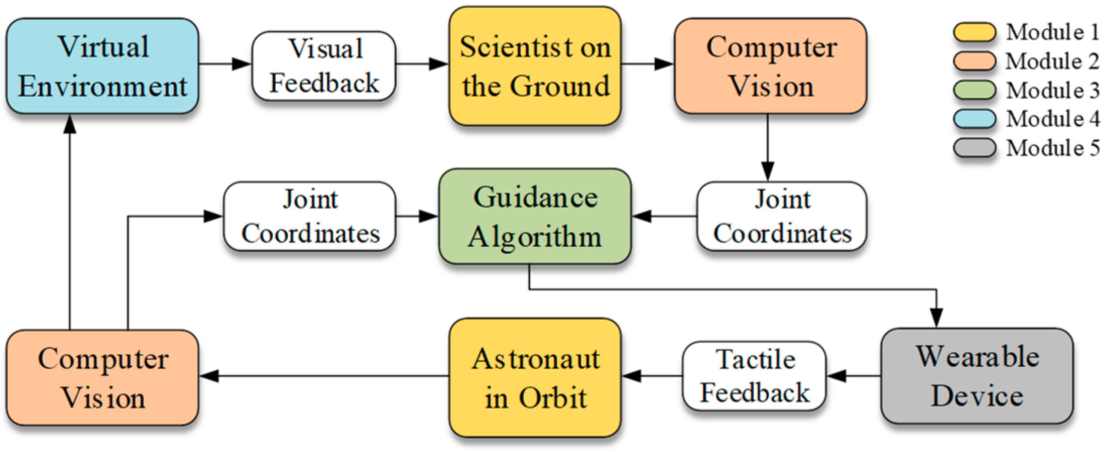
This research utilized the theory of “haptic guidance” [6], combined with computer vision technology and virtual reality technology, to construct an operational guidance system for ground scientists and astronauts. The guidance system contains five modules, as shown in Figure 1. The first module is the ground scientist and astronaut. The scientist makes a movement, and the astronaut copies the movement. Module 2 tracks the movements of the scientist and astronaut. The movement information is sent to Module 3 (guidance algorithm) and used to drive an astronaut model in virtual environments (Module 4). The guidance algorithm compares the movement differences between scientist and astronaut and generates guidance feedback signals, which are sent to the wearable vibrotactile device (Module 5).
In our work, the movements of the scientist and astronaut were tracked by one Kinect V2 sensor, respectively, and the data were sent to the virtual environment developed by Unity3D for data processing and scene driving. Microsoft Kinect is a low-cost and non-invasive motion caption sensor [16], which can track the major joints of the human body in a three-dimensional way (x, y, and z-axes), and the sensor exhibits good performance in motion capture. For example, Eftychios Protopapadakis et al. [17] applied a Kinect sensor to the identification of dance poses. Lin Yang et al. [18] used three Kinect V2 for markerless gait tracking. Alessandro Napoli compared Kinect with professional grad Qualisys motion capture system [19]. Their results showed that Kinect provides adequate performance in tracking joint center displacements. The recognition accuracy error of Kinect V2 is (0.0283 ± 0.0186 m) [20].
The wearable device used continuous vibrotactile stimulation as guidance instructions, and vibration stimulation was provided using an attractive method (move toward the vibration). Compared with the exoskeleton force feedback device, vibrotactile stimulation is more portable and has low power consumption, and, compared with electrical tactile stimulation, vibrotactile stimulation is safer and more comfortable for users.
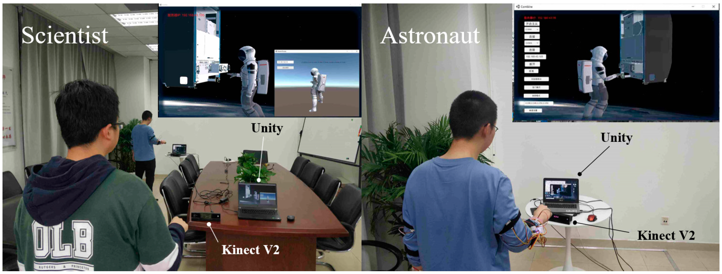
The system was divided into two parts: the master part and the slave part. As the master, the scientist on the ground guides the on-orbit astronaut in the slave part. We built a virtual experimental environment based on the real space science experiments scenes, which consisted of experimental equipment and virtual astronaut. Participants were able to control virtual astronauts to interact with experimental equipment. Scientists on the master side were able to see real-time visual feedback from virtual astronauts and equipment, while the astronauts could not observe the scientists. We set up three experiments to evaluate the effectiveness and feasibility of the system. The setting of the experimental environment is shown in Figure 2.
3. System Implementation
The operational guidance system consisted of movements capture and data processing, guidance algorithm, and wearable device of vibrotactile stimulation. The specific implementation of each part is described next.
3.1. Wearable Device
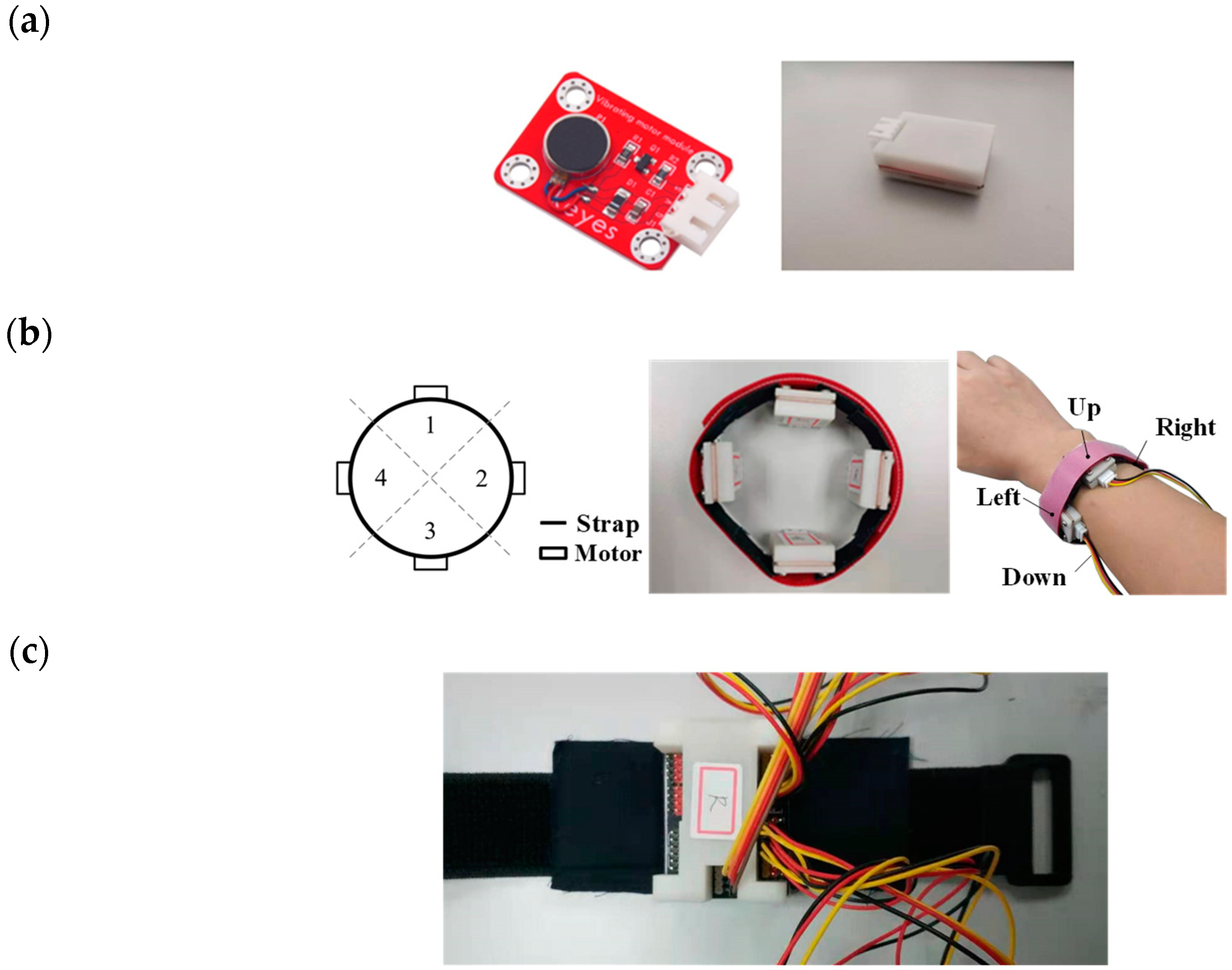
Tactile feedback of each arm is provided by two vibrotactile armbands, with four vibration actuator modules are placed at quadrants at each armband. The actuator module is a DC eccentric rotary motor, and the amplitude can be controlled by changing the PWM duty ratio. Figure 3a,b shows the vibration actuator module and the structure of the single armband. We defined the position of the motor from the user’s perspective when the user’s arms are stretched horizontally forward and palms down. The wearable device adopts a split design, divided into the left part and right part. Each part is controlled by an Arduino Nano MCU, as shown in Figure 3c.
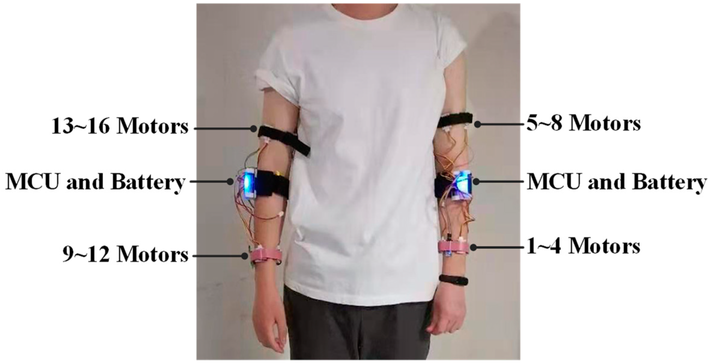
The device is powered by two 850 mAh Li-ion batteries. The normal service time is maintained for more than 3 h, and the standby time is maintained for more than 48 h. Two Bluetooth modules (HC-05) provide wireless communication with the computer. Figure 4 shows one user wearing a device.
3.2. Movements Capture, Data Processing
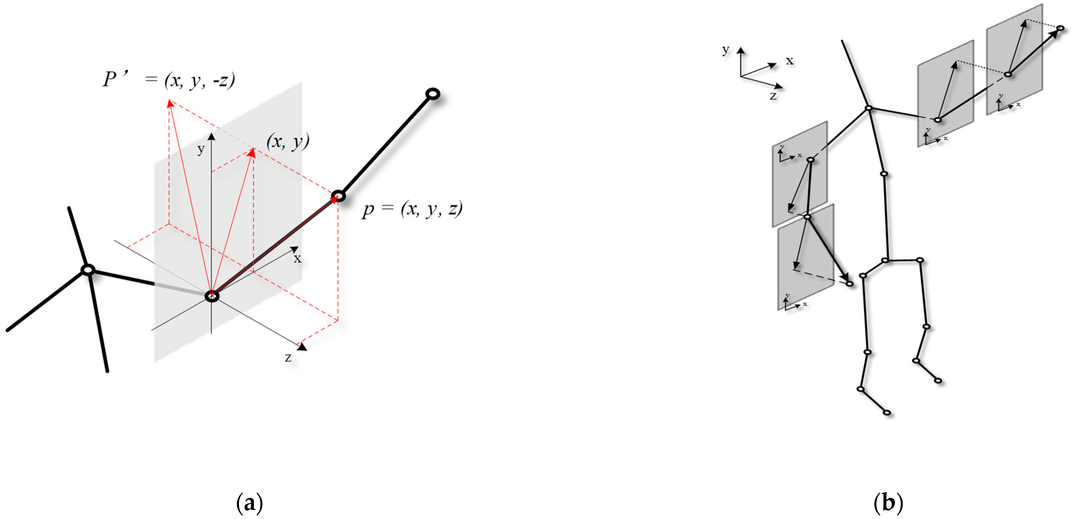
Our system tracks 25 human joints the sensor provides, and the joints data can be used to drive the virtual astronaut in the virtual environment developed by Unity 3D. Due to the differences in arm length and skeleton structure of different people, the coordinates of the joints the sensor tracks still have errors even if their movements are the same. Therefore, we converted the 3D point cloud data of Kinect into quaternions of each joint and mapped the 15 joints in Kinect coordinate to humanoid skeleton structure in Unity 3D. In this way, different users can be matched to the same virtual astronaut model, which solves the problems caused by the differences in the user’s arm length and skeleton structure. The mapping relationship is shown in Table 1. We recorded the coordinates of the shoulder (LeftUpperArm, RightUpperArm), elbow (LeftLowerArm, RightLowerArm), and wrist (LeftHand, RightHand) joints in the humanoid skeleton, used the vector of the elbow joint points to the shoulder joint to represent the posture of the upper arm, and used the vector of the wrist joint points to the elbow joint to represent the posture of the lower arm.
The length of two posture vectors is a fixed value, that is, the length of the virtual astronaut’s lower arm and upper arm. Therefore, once the x and y coordinates of a posture vector are determined, there are only two solutions for the z coordinate of this vector (shown in Figure 5a).
where represents the length of the posture vector.
Since most of the postures of the experiment task are in front of the trunk (z > 0), we can omit the value of the z-axis, and the three-dimensional posture vector is thus mapped to the two-dimensional coordinate system. Figure 5b shows four posture vectors mapped to 2D coordinates.
The posture vectors are calculated as follows:
where represents the posture vector of the lower arm, represents the posture of the upper arm, and , , , , , represent the x-axis value and y-axis value of the wrist, elbow, and shoulder joint, respectively. Then, the movements of human arms can be represented by four posture vectors: for the left lower arm, for the left upper arm, for the right lower arm, and for the right upper arm.
3.3. Guidance Algorithm
In specific space science experiments, astronauts’ main movements are completed by their upper limbs. Therefore, the operation algorithm takes the upper limb posture vectors of the master and slave as input, and the output is the guidance instructions for a wearable device. Two thresholds are set to represent the minimum acceptable posture error between master and slave. When the error is below the threshold, we determined that the two postures of the master and slave are the same. Additionally, we found the threshold with a preferable guidance effect in two tests.
The left lower arm was used as an example to introduce the master–slave operation guidance algorithm, and other sections follow the exact same approach. The posture vectors of the left lower arm of master and slave are separately expressed as
Additionally, the difference between the two vectors is used to represent the posture error of the master and slave:
As mentioned above, when ( is the set threshold), the master and slave postures are believed to be consistent. When , we decompose into two vectors in x-axis and y-axis directions expressed as , . Table 2 shows the mapping relationship between and output guidance information. is the Euclidean distance, and the calculation is as follows:
To search for the optimal threshold, two participants familiar with the system participated in the experiment. The threshold was gradually reduced, and then we conducted an operational guidance test for each threshold. We recorded the upper limb posture vector of the master participant in advance and sent the recorded posture vector to the slave participant successively during the operational guidance. The slave participant completed the operation according to the guidance presented by the wearable device.
After completing the test of each threshold, we recorded the posture vectors of the master and slave, respectively, and the error between master and slave was calculated using the following formula:
where, represents the master and slave posture vectors of the frame data, respectively. Additionally, the total error of the frame data is represented by the mean values of the four posture vectors as follows:
where the N represents the number of data frames.
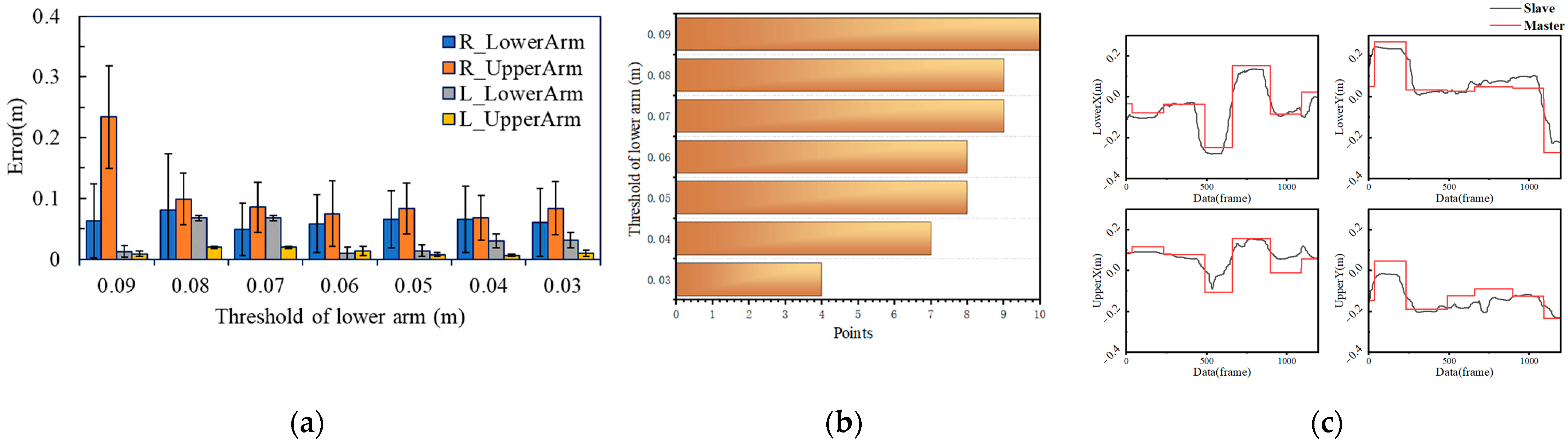
First, to search for the optimal threshold of the lower arm, the threshold of the upper arm was set at a high level (0.10 m). The initial threshold of the lower arm was set to 0.09 m, with a decrease of 0.01 m each time, and the final value was 0.03 m. We counted the mean and variance of the guidance error of the same operation with different thresholds. Figure 6a shows the mean and variance of the four posture vector errors. The maximum average error is 0.079845 when the threshold value of the lower arm is 0.09 m, and the average errors at the threshold of 0.05 m, 0.04 m, and 0.03 m are distributed between 0.0423 m and 0.0462 m. As shown in Figure 6b, the participant used 1~10 points to evaluate the difficulty of the following guidance, and when the threshold was reduced to 0.03 m, the participant reported that the device would vibrate even when his arm moved slightly, and considerable attention was required to maintain the target posture. Therefore, combined with the objective error and subjective evaluation, the threshold of the lower arm was set to 0.04 m. Figure 6c shows the posture vector difference of the right arm between the master and slave.
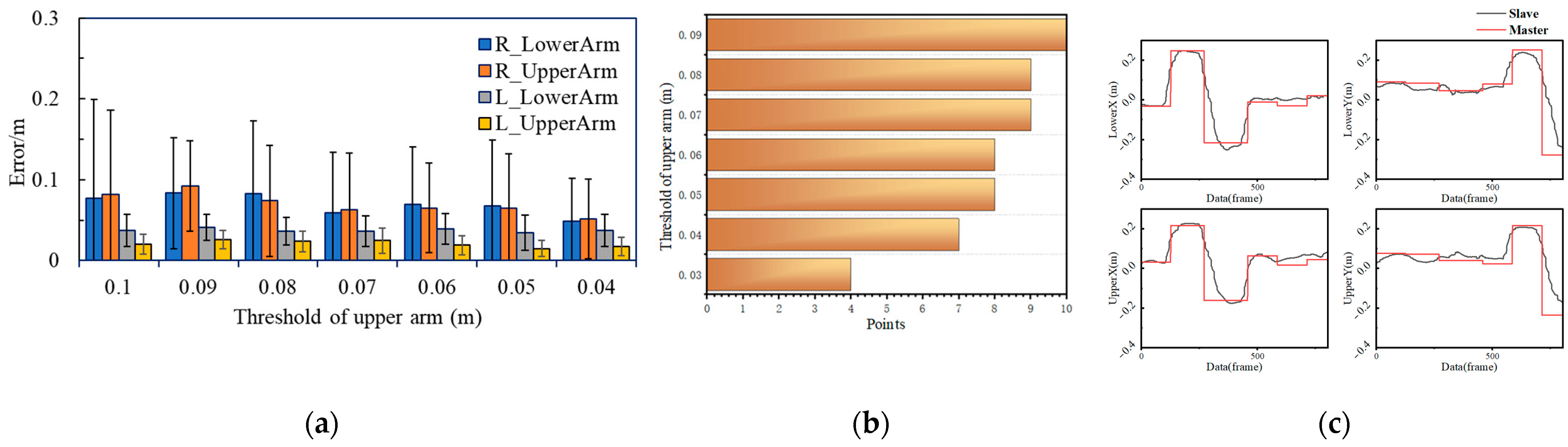
Secondly, the threshold of the lower arm was set to 0.04, and the threshold of the upper arm was reduced from 0.10 m to 0.04 m with a decrease of 0.01 m each time. The results are shown in Figure 7a, indicating the mean and variance of the four posture vector errors, and Figure 7b shows the subjective evaluation results. The waveforms of the right arm posture vectors of the master and slave are shown in Figure 7c. According to the test results, the threshold of the upper arm was set to 0.05 m.
4. Experiments
We simulated the task scene of the space science experiment and built the wearable vibrotactile operational guidance system. Three different experiments were set up to evaluate the effectiveness and feasibility of the proposed operational system. Nine subjects took part in the experiments (seven males, two females; age mean = 23). None of them was left-handed. Each subject participated in the subjective questionnaire survey about the experiment.
4.1. Experiment 1: Perceptual Test
To ensure that subjects can accurately distinguish and well understand the vibrotactile stimuli from different positions, we carried out a perception test in the following three conditions:
- C1: Using a single vibration source, we conducted 50 trials. For each trial, the wearable device generated a random vibrotactile stimulus;
- C2: Using two vibration sources, we conducted 50 trials, and for each trial, the wearable device randomly and simultaneously generated two vibrotactile stimuli at different positions;
- C3: Using four vibration sources, we conducted 10 trials, and for each trial, the wearable device generated four stimuli on the basis of predetermined order.
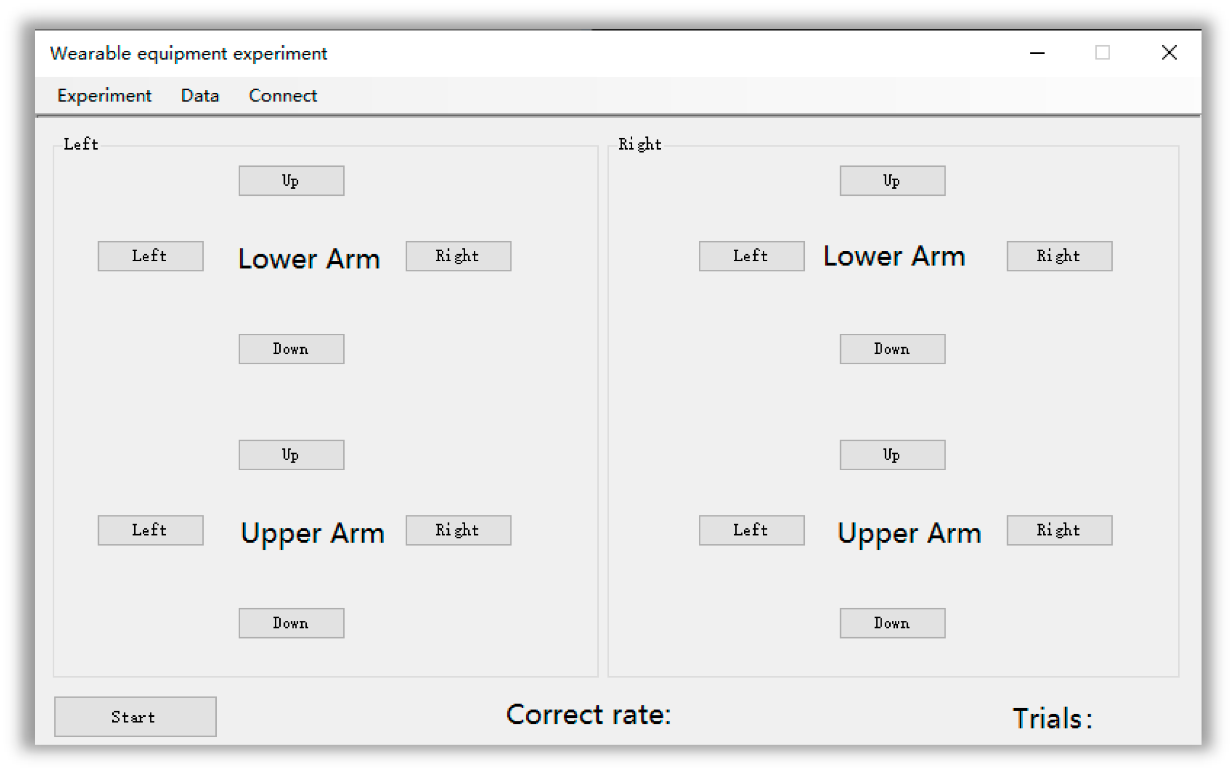
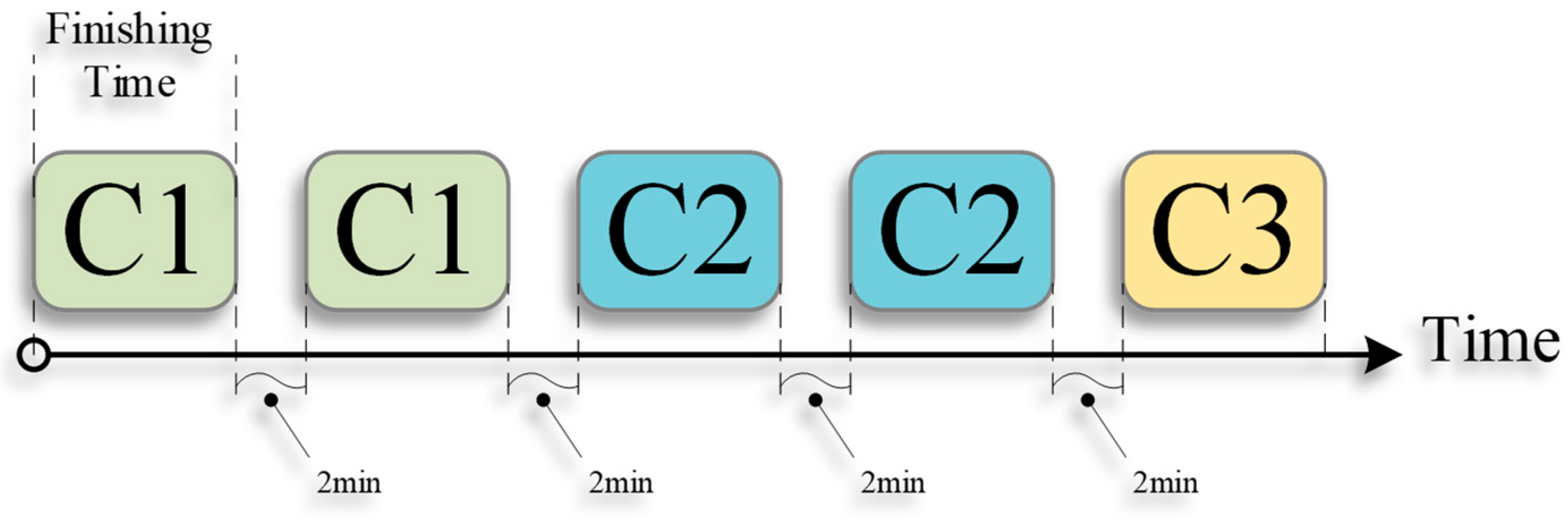
Before the experiment, we explained the position and direction of the vibration stimulus in detail to the participants. Then, the subjects were asked to wear the device and sit in front of a computer with their forearms placed on the table. They should select the answer at the experimental interface shown in Figure 8. Each subject experimented in the order of the schedule shown in Figure 9. Subjects had sufficient time to report the position and direction of the perceived stimuli, and they had two minutes of rest after each experiment.
To evaluate the subjects’ perception of vibration stimuli, we recorded the correct rate and finishing time of each experiment. We defined the correct rate of an experiment as the number of correct answers reported by the subjects divided by the total number of trials. Additionally, the finishing time was defined as the interval between the first stimulus generation and the last stimulus reported by the subject.
4.2. Experiment 2: Guiding Training
In order to make the subjects familiar with the operational guidance system more quickly, we decomposed five continuous operation actions into 22 discrete postures and presented the corresponding guidance instructions to the subjects successively. Each subject was trained twice. In the first training, they were told how to move their arms when they sensed vibrations in different positions and directions. The second training was conducted without our prompts. After the experiment, all subjects participated in the subjective questionnaire.
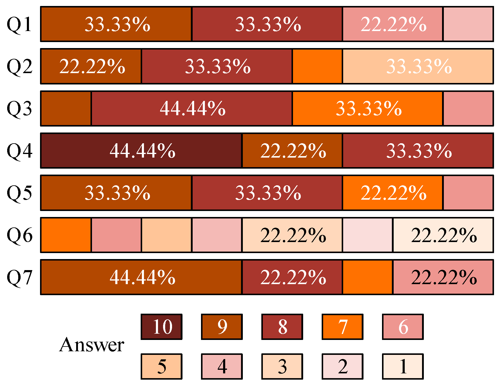
As shown in Table 3 and Figure 10, the subjective questionnaire mainly deals with the wearable device and the operational guidance system. For each question, subjects had to answer by assigning a score ranging from 1 (totally disagree) to 10 (totally agree).
Question Q1 (familiar to the operational guidance system) was positively rated, with a mean of 7.23 and standard deviation of 1.98. For Q2 and Q3, related to the wearability of the device, the mean responses were 7.44 and 7.55 with a standard deviation of 1.23 and 0.88, respectively. With the training in Experiment 2, the subjects were more familiar with the operational guidance system, and it was easy and comfortable for most of them to wear the device. Questions Q4 showed a positive result, with a mean of 9.11 and a standard deviation of 0.93. For most subjects, the vibration stimuli from different positions and directions could be clearly distinguished (Q5 mean 7.89, standard deviation 1.05). For Q6, the mean was 3.56, and the standard deviation was 2.12, which showed that noise produced by vibration motors has little impact on the perception of vibration stimuli. For the last question, most subjects could understand the meaning of guiding instruction (Q7 mean 7.89, standard deviation 1.27).
4.3. Experiment 3: Master–Slave Operational Guidance Experiment
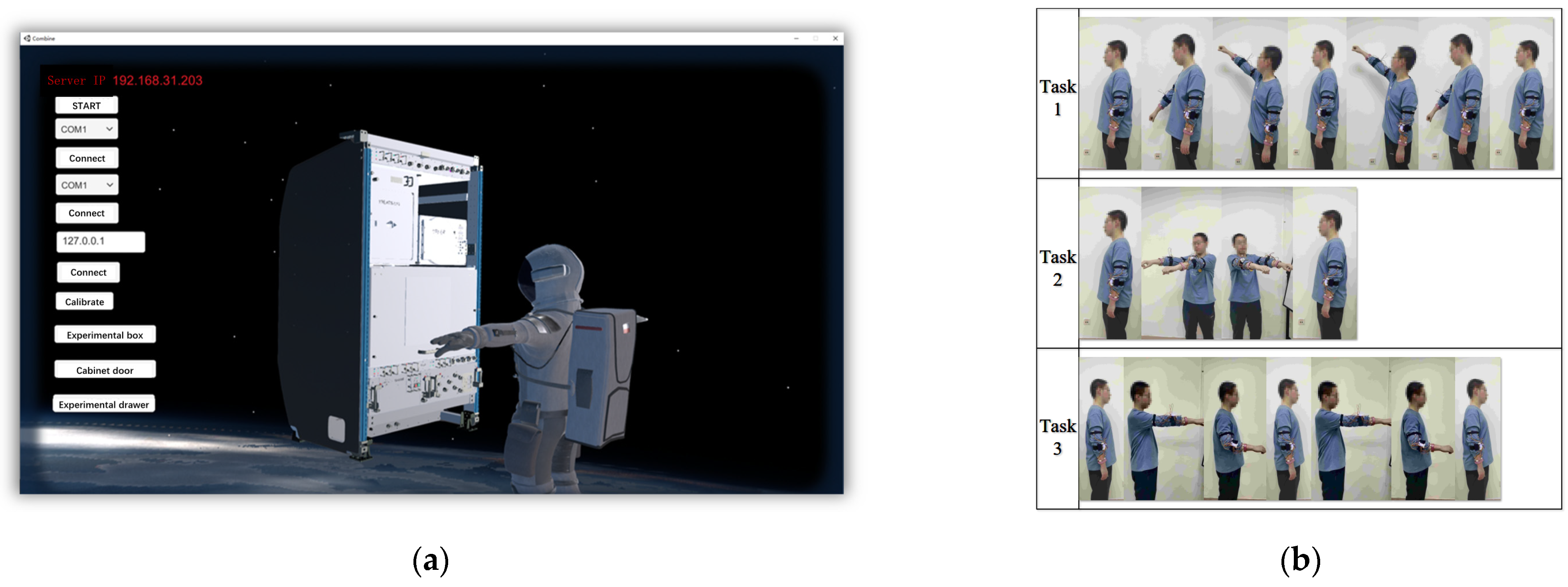
To verify the feasibility of tactile guidance interaction in a non-visual environment, we simulated the experimental tasks of the space science experiment and built the experimental scene for Experiment 3, as shown in Figure 2, combined with the specific operational tasks of the space science experiment for the expert in the master role and the subjects in the slave role. All subjects participated in Experiment 3 after finishing the training in Experiment 2, and they had a certain understanding of the operational guidance system. In the experiment, experts and subjects naturally stood in front of the Kinect sensor separately, and the expert was invisible to the subjects. The expert performed the operations in turn, and the subject needed to operate with the guidance of a wearable vibrotactile device, driving the astronaut model in a virtual scene to complete the tasks. We selected three representative tasks in the space science experiment. Subjects did not know the operations of the tasks in advance, and they could only operate under the guidance of the device. Subjects needed to repeat the attempt until the first success, and it was regarded as a failed attempt when the vibration of the wearable device exceeded 15 s. The virtual experiment scenes are shown in Figure 11a, and the decomposition of three tasks is shown in Figure 11b.
We recorded the posture vectors of 10 subjects that participated in the experiment, as well as the finishing time of each task. Additionally, we also recorded the completion of tasks in the Unity virtual experimental scene, that is, the number of attempts when the subjects completed the task successfully for the first time.
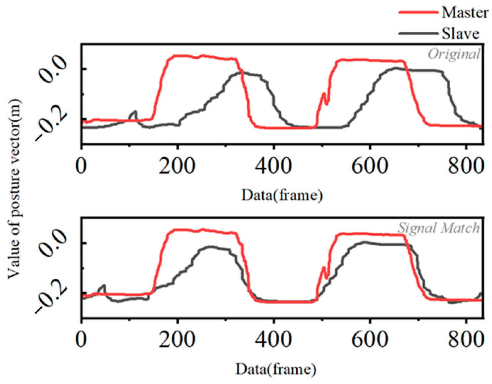
Due to the communication delay between the wearable device and computer, and the reaction time of the subjects, the motion of the slave is always lagging behind the master. To evaluate the effect of operation guidance, we used signal matching for the posture vector between slaver and master and recorded the delay of each task, as shown in Figure 12.
5. Results and Discussion
5.1. Experiment 1: Results
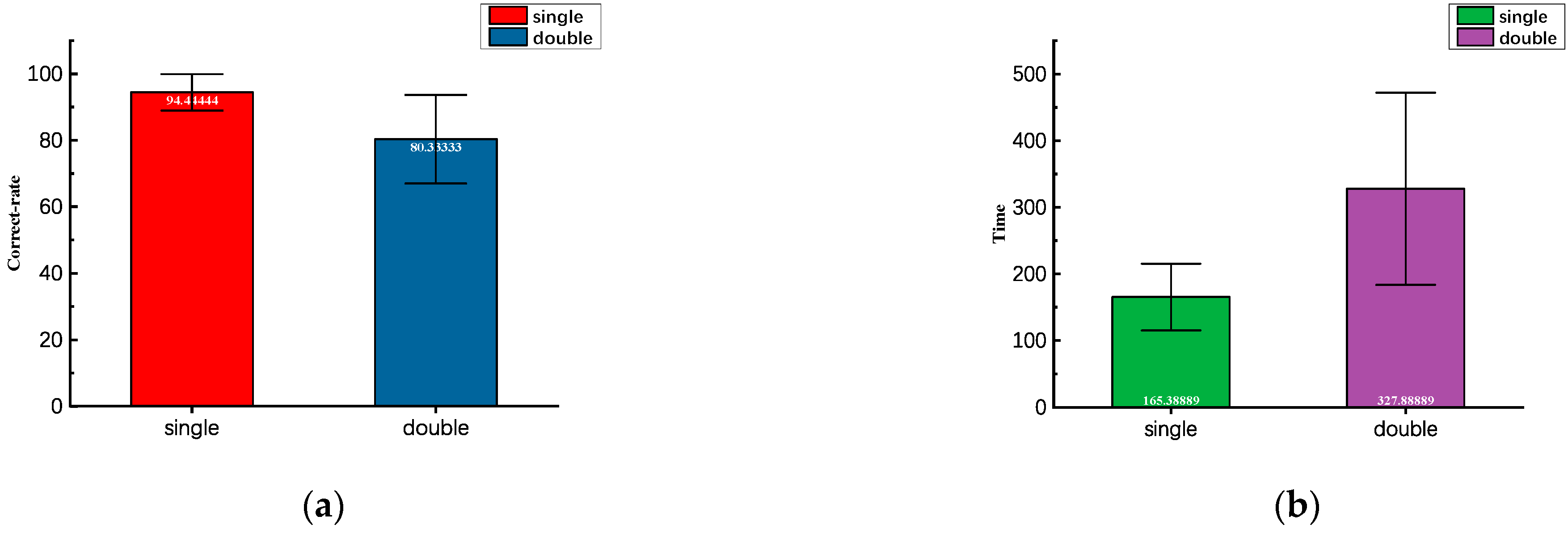
The results of Experiment 1 showed that the test for C1 (single vibration source) has an average accuracy of 94.4% and a standard deviation of 3.67. The test for C2 (double vibration sources) has an average accuracy of 83.3% and a standard deviation of 8.87. In terms of the time for task accomplishment, the mean value of C1 is 165.389 s, while for C2, it is 327.89 s. As shown in Table 4, the correct rate of C1 is generally above 90%. Subjects reported that it is easy to confuse the stimuli in neighboring directions (especially the inner side of the upper arm). Additionally, more obvious in C2, subjects were more likely to be confused when they perceived two vibration stimuli at different positions at the same time, as can be seen from Table 3, where the correct rate of C2 was significantly lower than that of C1. The finishing time is shown in Figure 13b, which also shows this result. Moreover, the correct rate of the second test of C2 is generally lower than that of the first test; subjects reported that lingering vibration stimuli would lead to the weakening of perception.
The recognition correct rate of vibration on different sides is significantly lower than that on the same side. C3 shows a positive result with an average correct rate of 85.1%. Overall, the accuracy and finishing time are satisfactory. The result of the perceptual test for Experiment 1 showed that participants were able to correctly distinguish vibration stimuli from different positions and directions.
5.2. Experiment 3: Results
As regards the three tasks in Experiment 3, Table 5 and Table 6 show the statistical results of the number of attempts when the subjects completed the tasks successfully for the first time. It is worth noting that Task 1 and Task 3 only involve the right arm, while Task 2 requires both arms to act simultaneously. Subjects reported that when conducting the operation of Task 2, it was confusing sometimes that both arms perceived vibration stimulation at the same time, and when conducting the operations of Task 1 or Task 3, they could focus on the stimulation perception on one arm. The results showed that Task 1 and Task 3 have only right arm involvement, and subjects generally succeed in accomplishing tasks after one or two attempts, while Task 2 involves both arms, and subjects can accomplish the task successfully after two or three attempts.
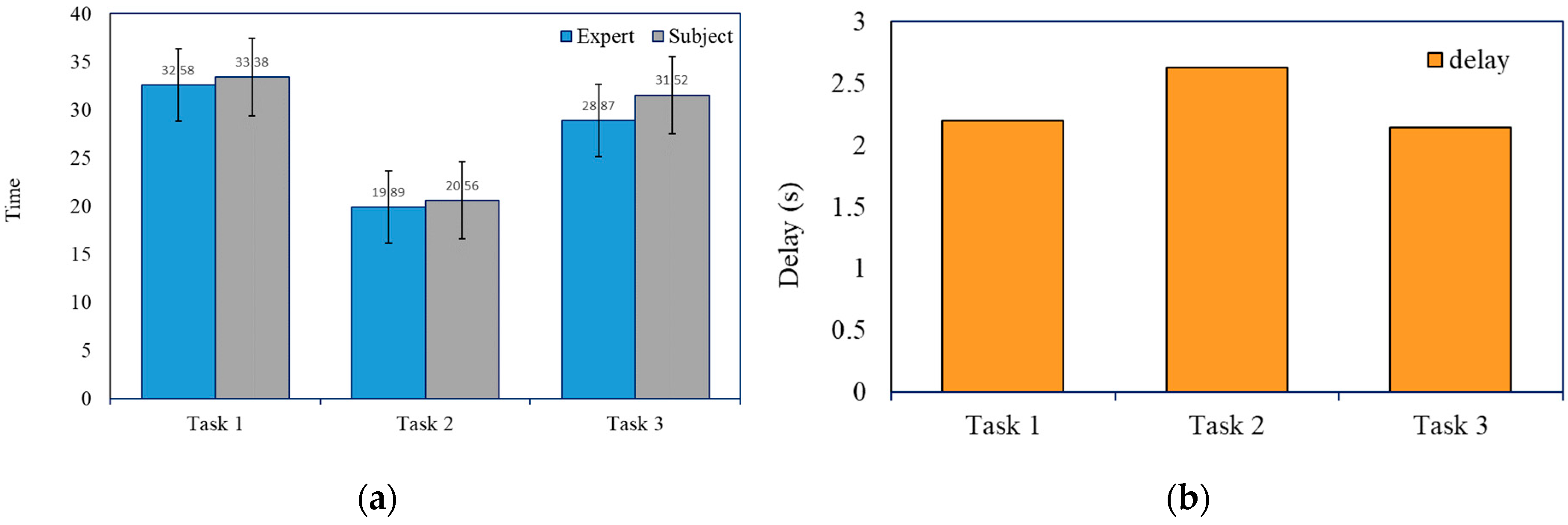
Moreover, we recorded the finishing time and delay between the master and slave. As shown in Figure 14, the mean and standard deviation of finishing time, for the master (expert) are 32.58, 19.89, 28.87 s, and 8.66, 3.09, 9.73 s for Tasks 1, 2, and 3. For the slave (subject), they are 33.38, 20.56, 31.52 s, and 8.38, 3.61, and 6.09 s. The mean and standard deviation of delay are 2.20, 2.63, 2.14 s, and 1.28, 1.11, 0.86 s. One-way ANOVA showed that there was no significant difference between finishing time of expert and subject, Task 1 (F = 0.003, p > 0.960, a = 0.05), Task 2 (F = 0.197, p > 0.678, a = 0.05), Task 3 (F = 0.001, p > 0.972, a = 0.05).
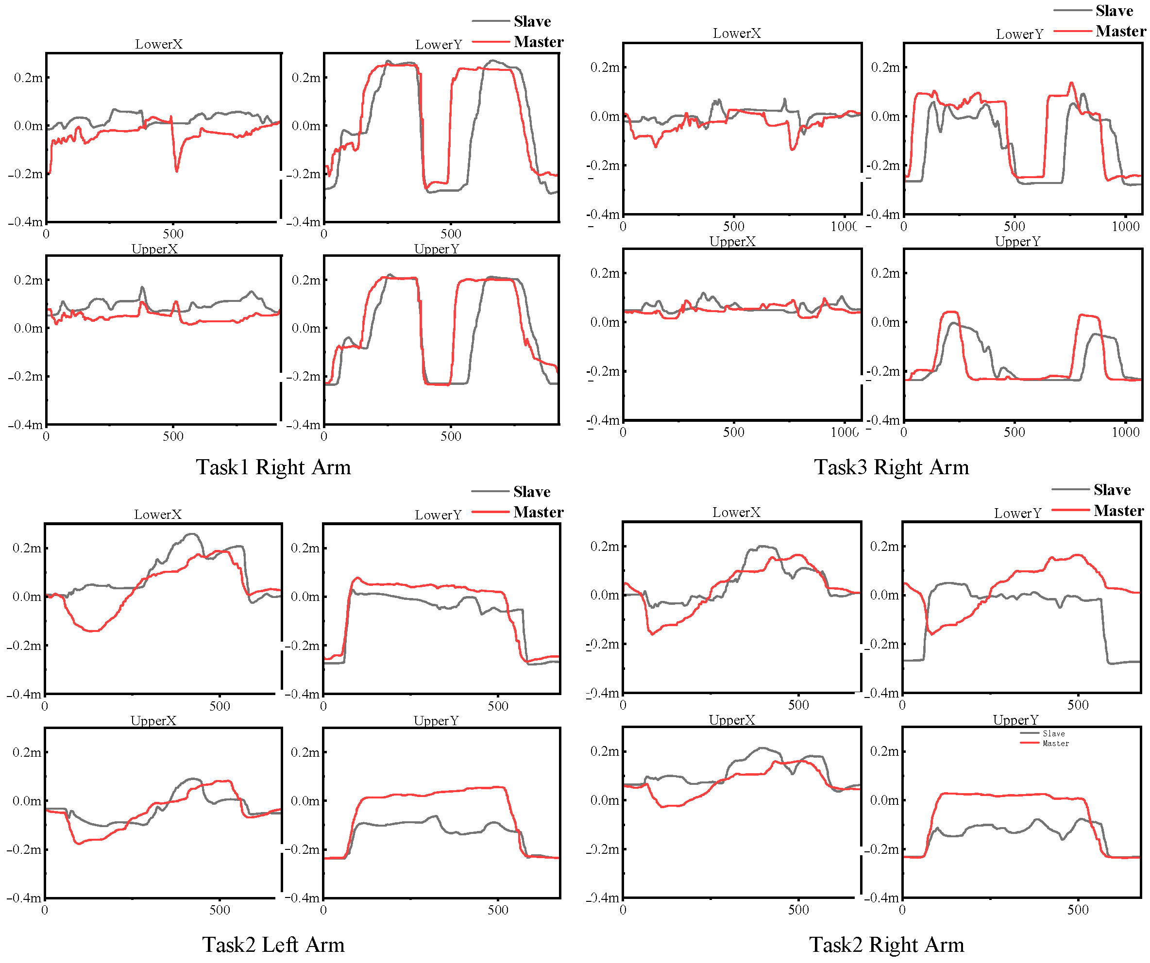
To intuitively show the effect of guidance, the recorded posture vectors are plotted as a waveform, shown in Figure 15. The results of the operation guidance experiment, reported in Figure 13 and Figure 15, showed that the guidance instructions can be clearly recognized and understood. The subjects were able to accomplish the virtual operation tasks with 2 or 3 attempts under the guide of the master. Furthermore, the task finishing time of the subject is almost the same as that of the expert, and the average delay is less than 3 s. By observing the trend of the waveform in Figure 15, it can also be found that the subjects can follow the posture of the expert arm well, which verifies the feasibility of the operational guidance system.
6. Conclusions
This work proposed an operational guidance system for space science experiments and verified the feasibility of the wearable vibrotactile device for operational guidance. The system tracks and compares the postures of the master and slave, and then presents vibration stimulation to guide the action of the slave end. Although experiments in a virtual environment showed positive results, there is still a long way to its successful practical application in space science experiments. There are some shortages in our approach, which we will address in future work.
The first is that we ignored the DOF of the arm rotation around itself. As a result, when conducting the operation guidance, both the master and slave should keep the back of their hands up to ensure that the directions of their arms are consistent, which is because Kinect V2 sensor cannot track the rotation angle of the arm around itself. To solve this issue, we plan to utilize inertial sensors to track the rotation degree of freedom of the arms around itself, improve the guidance algorithm, and verify the system with more complex tasks.
The second is that we used continuous vibrotactile stimulation to provide guidance instructions, and as the subjects reported in Experiment 1, the long stimulation weakens perception to vibration. The next step will change the vibration mode to discrete and set the experiment to find a better interval time. In addition, we would like to utilize different types of tactile feedback, for example, kinesthetic feedback, vibration combined with skin-stretch feedback, and other vibrative actuators [21]. Although the algorithm that omits the z-axis has shown a positive result in the posture in front of the trunk, introducing Z-axis into the algorithm is also one of the future works.
The third is that the user (whether the scientists or astronauts) must be in the right and appropriate position where Kinect works properly; this has a large impact on practical applications, especially when users are very close to the device, and using multiple Kinect sensors or other motion capture devices [9,10,11] will be considered in a future work. The fourth is the delay issue of space–ground communication in space science experiments, which was not considered in the simulation experiments we had set up. Next, we will set up delay to simulate the communication between space and ground, further verifying the feasibility of the system in a high-delay environment and try to find a minimum acceptable time delay. The delay issue is a significant issue in practical applications, and its solution needs further development of communication technology between space and ground. Further, we would like to combine our approach with VR or AR technology and take advantage of both, allowing the astronauts to see the difference in the action between themselves and scientists while being able to directly sense the action of scientists through the tactile channels.
In this paper, we proposed a vibrotactile guidance system composed of a Kinect V2 sensor, Unity 3D virtual environment, and a wearable device; the target is to be applied in space science experiments to establish a more efficient intuitive transparent interaction system between ground scientists and astronauts. We constructed a simulated experimental environment, tested the system combined with three tasks of space science experiments, and verified the feasibility of the system for operation guidance. The waveforms of the postures also show a preferable guiding effect. Participants can well follow the guidance to accomplish the experimental task after receiving guidance training, and the experimental results show that the method has an application prospect.
Author Contributions
Conceptualization, G.Y. and G.-Y.L.; investigation, Y.W. and C.H.; writing—original draft preparation, Y.W.; writing—review and editing, G.-Y.L. and Y.-H.W. All authors have read and agreed to the published version of the manuscript.
Funding
This research received no external funding.
Institutional Review Board Statement
The study was conducted according to the guidelines of the Declaration of Helsinki, and approved by the Institutional Review Board of Beihang University.
Informed Consent Statement
Informed consent was obtained from all subjects involved in the study.
Data Availability Statement
Not applicable.
Conflicts of Interest
The authors declare no conflict of interest.
References
- Hai-Peng, J.; Jing-Min, X.; Wei, H.; Yi-Bing, D.; Nan-Ning, Z.H. Space station: Human exploration in space. Acta Autom. Sin. 2019, 45, 1799–1812. [Google Scholar]
- Lin, H.; Wei-Wei, F.; Hai-Ming, W. Analysis and Enlightenment of Scientific Research and Application Activities on ISS. Manned Spacefl. 2019, 6, 834–840. [Google Scholar]
- Karasinski, J.A.; Joyce, R.; Carroll, C.; Gale, J.; Hillenius, S. An augmented reality/internet of things prototype for just-in-time astronaut training. In Proceedings of the International Conference on Virtual, Augmented and Mixed Reality, Vancouver, BC, Canada, 9–14 July 2017; pp. 248–260. [Google Scholar]
- Lieberman, J.; Breazeal, C. TIKL: Development of a wearable vibrotactile feedback suit for improved human motor learning. IEEE Trans. Robot. 2017, 23, 919–926. [Google Scholar] [CrossRef]
- MacLean, K.E. Putting haptics into the ambience. IEEE Trans. Haptics 2009, 2, 123–135. [Google Scholar] [CrossRef]
- Feygin, D.; Keehner, M.; Tendick, R. Haptic guidance: Experimental evaluation of a haptic training method for a perceptual motor skill. In Proceedings of the 10th Symposium on Haptic Interfaces for Virtual Environment and Teleoperator Systems, HAPTICS 2002, Orlando, FL, USA, 24–25 March 2002; pp. 40–47. [Google Scholar]
- Park, W.; Korres, G.; Moonesinghe, T.; Eid, M. Investigating haptic guidance methods for teaching children handwriting skills. IEEE Trans. Haptics 2019, 12, 461–469. [Google Scholar] [CrossRef]
- Rosenthal, J.; Edwards, N.; Villanueva, D.; Krishna, S.; McDaniel, T.; Panchanathan, S. Design, implementation, and case study of a pragmatic vibrotactile belt. IEEE Trans. Instrum. Meas. 2010, 60, 114–125. [Google Scholar] [CrossRef]
- Kim, Y.; Baek, S.; Bae, B.C. Motion capture of the human body using multiple depth sensors. ETRI J. 2019, 39, 181–190. [Google Scholar] [CrossRef]
- Liu, S.; Zhang, J.; Zhang, Y.; Zhu, R. A wearable motion capture device able to detect dynamic motion of human limbs. Nat. Commun. 2020, 11, 1–12. [Google Scholar] [CrossRef] [PubMed]
- Szczęsna, A.; Skurowski, P.; Lach, E.; Pruszowski, P.; Pęszor, D.; Paszkuta, M.; Wojciechowski, K. Inertial motion capture costume design study. Sensors 2017, 17, 612. [Google Scholar] [CrossRef] [PubMed] [Green Version]
- Wang, Z.; Zheng, R.; Kaizuka, T.; Shimono, K.; Nakano, K. The effect of a haptic guidance steering system on fatigue-related driver behavior. IEEE Trans. Hum.-Mach. Syst. 2017, 47, 741–748. [Google Scholar] [CrossRef]
- Devigne, L.; Aggravi, M.; Bivaud, M.; Balix, N.; Teodorescu, C.S.; Carlson, T.; Babel, M. Power wheelchair navigation assistance using wearable vibrotactile haptics. IEEE Trans. Haptics 2020, 13, 52–58. [Google Scholar] [CrossRef] [PubMed] [Green Version]
- Barontini, F.; Catalano, M.G.; Pallottino, L.; Leporini, B.; Bianchi, M. Integrating wearable haptics and obstacle avoidance for the visually impaired in indoor navigation: A user-centered approach. IEEE Trans. Haptics 2020, 14, 109–122. [Google Scholar] [CrossRef] [PubMed]
- Satpute, S.A.; Canady, J.R.; Klatzky, R.L.; Stetten, G.D. FingerSight: A Vibrotactile Wearable Ring for Assistance with Locating and Reaching Objects in Peripersonal Space. IEEE Trans. Haptics 2019, 13, 325–333. [Google Scholar] [CrossRef] [PubMed]
- Wang, T.; Li, C.; Wu, C.; Zhao, C.; Sun, J.; Peng, H.; Hu, B. A gait assessment framework for depression detection using kinect sensors. IEEE Sens. J. 2020, 21, 3260–3270. [Google Scholar] [CrossRef]
- Protopapadakis, E.; Voulodimos, A.; Doulamis, A.; Camarinopoulos, S.; Doulamis, N.; Miaoulis, G. Dance pose identification from motion capture data: A comparison of classifiers. Technologies 2018, 6, 31. [Google Scholar] [CrossRef] [Green Version]
- Yang, L.; Yang, B.; Dong, H.; El Saddik, A. 3-D markerless tracking of human gait by geometric trilateration of multiple Kinects. IEEE Syst. J. 2016, 12, 1393–1403. [Google Scholar] [CrossRef]
- Napoli, A.; Glass, S.; Ward, C.; Tucker, C.; Obeid, I. Performance analysis of a generalized motion capture system using microsoft kinect 2.0. Biomed. Signal Process. Control 2017, 38, 265–280. [Google Scholar] [CrossRef]
- Wei-Ying, W.u.; Yu, W.; Qin, L.; Xing-Jie, Y.; Tian-Yuan, C.; Fand, P. Positioning error and its spatial distribution of motion capture with Kinect. Beijing Biomed. Eng. 2014, 4, 344–348. [Google Scholar]
- Poncet, P.; Casset, F.; Latour, A.; Domingues Dos Santos, F.; Pawlak, S.; Gwoziecki, R.; Fanget, S. Static and dynamic studies of electro-active polymer actuators and integration in a demonstrator. Actuators 2017, 6, 18. [Google Scholar] [CrossRef] [Green Version]
Figure 1.
Module diagram of operational guidance system.

Figure 2.
Experimental environment setup. The master and slave, respectively, consisted of a Kinect V2 sensor and a computer with Unity 3D. Additionally, the participant in the slave part wore the vibrotactile feedback device.
Figure 2.
Experimental environment setup. The master and slave, respectively, consisted of a Kinect V2 sensor and a computer with Unity 3D. Additionally, the participant in the slave part wore the vibrotactile feedback device.

Figure 3.
Composition of the wearable device: (a) the vibration actuator module; (b) the structure of single armband; (c) Arduino Nano MCU installed in elastic belt.
Figure 3.
Composition of the wearable device: (a) the vibration actuator module; (b) the structure of single armband; (c) Arduino Nano MCU installed in elastic belt.

Figure 4.
A user wearing the device.

Figure 5.
(a,b) Four two-dimensional vectors for arm posture.

Figure 6.
The threshold experiment results of the lower arm: (a) the mean and variance of the four posture vector errors; (b) participant’s evaluation; (c) the right arm posture vectors of the master and slave.
Figure 6.
The threshold experiment results of the lower arm: (a) the mean and variance of the four posture vector errors; (b) participant’s evaluation; (c) the right arm posture vectors of the master and slave.

Figure 7.
The threshold experiment results of the upper arm: (a) the mean and variance of the four posture vector errors; (b) participant’s evaluation; (c) the right arm posture vectors of the master and slave.
Figure 7.
The threshold experiment results of the upper arm: (a) the mean and variance of the four posture vector errors; (b) participant’s evaluation; (c) the right arm posture vectors of the master and slave.

Figure 8.
Experimental interface of Experiment 1.

Figure 9.
Time schedule of Experiment 1.

Figure 10.
Total answers to the questions.

Figure 11.
(a) The virtual space science experiment developed by Unity 3D; (b) the decomposition of three task operations.
Figure 11.
(a) The virtual space science experiment developed by Unity 3D; (b) the decomposition of three task operations.

Figure 12.
Delay elimination of slave posture vector.

Figure 13.
Results of Experiment 1: (a) average correct rate of all subjects in C1 and C2; (b) average finishing time of all subjects in C1 and C2.
Figure 13.
Results of Experiment 1: (a) average correct rate of all subjects in C1 and C2; (b) average finishing time of all subjects in C1 and C2.

Figure 14.
Result of Experiment 3: (a) finishing time(s) of expert and subject; (b) delay(s) of Tasks 1, 2, and 3.
Figure 14.
Result of Experiment 3: (a) finishing time(s) of expert and subject; (b) delay(s) of Tasks 1, 2, and 3.

Figure 15.
Posture vectors of Tasks 1, 2, and 3.


Table 1.
The mapping relationship between Kinect structure and humanoid structure.
| Kinect Joint | Humanoid Joint |
|---|---|
| SpineBase | Hips |
| SpineMid | Spine |
| Neck | Neck |
| ShoulderLeft | LeftUpperArm |
| ElbowLeft | LeftLowerArm |
| WristLeft | LeftHand |
| ShoulderRight | RightUpperArm |
| ElbowRight | RightLowerArm |
| HipLeft | LeftUpperLeg |
| KneeLeft | LeftLowerLeg |
| AnkleLeft | LeftFoot |
| HipRight | RightUpperLeg |
| KneeRight | RightLowerLeg |
| AnkleRight | RightFoot |
| WristRight | RightHand |
Table 2.
The mapping relationship between and output guidance information.
| Guidance Information | Output Instructions | ||
|---|---|---|---|
| NONE | “−1” | ||
Additionally, points to the positive direction of x-axis | Right motor vibrates Move toward right | “002” | |
And points to the negative direction of x-axis | Left motor vibrate Move toward left | “004” | |
| and points to the positive direction of y-axis | Up motor vibrates Move toward up | “001” | |
| and points to the negative direction of y-axis | Down motor vibrates Move toward down | “003” | |
Table 3.
Experiment 2: question results.
| Questions | Mean | Std. Dev |
|---|---|---|
| Q1 I am familiar with the wearable haptic device. | 7.22 | 1.97 |
| Q2 It was easy to wear the haptic device. | 7.44 | 1.24 |
| Q3 I was feeling comfortable while wearing and using the device. | 7.56 | 0.88 |
| Q4 The intensity of the vibration does not make me feel uncomfortable. | 9.11 | 0.93 |
| Q5 It is very clear to recognize vibrations in different positions. | 7.89 | 1.05 |
| Q6 The noise from vibrating motors affects the recognition of the vibration position. | 3.56 | 2.13 |
| Q7 I can clearly understand the meaning of the wearable device’s guidance. | 7.89 | 1.27 |
Table 4.
Results of Experiment 1: correct rate of each subject.
| Accuracy of C1 | Accuracy of C2 | |||
|---|---|---|---|---|
| Subjects | First | Second | First | Second |
| 1 | 98% | 86% | 72% | 76% |
| 2 | 94% | 98% | 92% | 76% |
| 3 | 94% | 94% | 90% | 76% |
| 4 | 98% | 94% | 70% | 62% |
| 5 | 94% | 96% | 94% | 90% |
| 6 | 92% | 94% | 82% | 70% |
| 7 | 100% | 96% | 90% | 86% |
| 8 | 90% | 88% | 84% | 78% |
| 9 | 98% | 96% | 80% | 78% |
| Average | 95.33% | 93.56% | 83.78% | 76.89% |
Table 5.
Number of attempts of each subject.
| Number of Attempts | |||
|---|---|---|---|
| Subjects | Task 1 | Task 2 | Task 3 |
| 1 | 2 | 2 | 2 |
| 2 | 1 | 3 | 2 |
| 3 | 1 | 3 | 1 |
| 4 | 1 | 2 | 1 |
| 5 | 1 | 3 | 1 |
| 6 | 2 | 4 | 2 |
| 7 | 1 | 2 | 1 |
| 8 | 1 | 1 | 1 |
| 9 | 2 | 1 | 3 |
| Average | 1.33 | 2.33 | 1.56 |
Table 6.
Statistics of attempts.
| Mean | Std Dev | |
|---|---|---|
| Task 1 | 1.33333 | 0.50 |
| Task 2 | 2.33333 | 1.00 |
| Task 3 | 1.55556 | 0.73 |
Publisher’s Note: MDPI stays neutral with regard to jurisdictional claims in published maps and institutional affiliations. |
© 2021 by the authors. Licensee MDPI, Basel, Switzerland. This article is an open access article distributed under the terms and conditions of the Creative Commons Attribution (CC BY) license (https://creativecommons.org/licenses/by/4.0/).
Share and Cite
MDPI and ACS Style
Wang, Y.; Yu, G.; Liu, G.-Y.; Huang, C.; Wang, Y.-H. Vibrotactile-Based Operational Guidance System for Space Science Experiments. Actuators 2021, 10, 229. https://0-doi-org.brum.beds.ac.uk/10.3390/act10090229
AMA Style
Wang Y, Yu G, Liu G-Y, Huang C, Wang Y-H. Vibrotactile-Based Operational Guidance System for Space Science Experiments. Actuators. 2021; 10(9):229. https://0-doi-org.brum.beds.ac.uk/10.3390/act10090229
Chicago/Turabian StyleWang, Yi, Ge Yu, Guan-Yang Liu, Chao Huang, and Yu-Hang Wang. 2021. "Vibrotactile-Based Operational Guidance System for Space Science Experiments" Actuators 10, no. 9: 229. https://0-doi-org.brum.beds.ac.uk/10.3390/act10090229
Note that from the first issue of 2016, this journal uses article numbers instead of page numbers. See further details here.