
Mechanism and Experiment Study of Non-Contact Ultrasonic Assisted Grinding


1
School of Mechanical and Electrical Engineering, Guangzhou University, Guangzhou 510006, China
2
School of Computer and Information, Qiannan Normal University for Nationalities, Duyun 558000, China
*
Author to whom correspondence should be addressed.
Actuators 2021, 10(9), 238; https://0-doi-org.brum.beds.ac.uk/10.3390/act10090238
Submission received: 20 July 2021
/
Revised: 9 September 2021
/
Accepted: 9 September 2021
/
Published: 14 September 2021
(This article belongs to the Special Issue Ferroelectric Materials and Piezoelectric Actuators)
Abstract
:Ultrasonic-assisted grinding processing can effectively reduce the surface roughness and enhance the processing efficiency in the processing of hard and brittle materials. However, the most common ultrasonic assisted grinding is a type of contact ultrasonic grinding where the grinding tool directly contacts the workpiece, which means that it is necessary to accurately control the pre-pressure of the grinding tool on the workpiece. The control of pre-pressure will inevitably increase the complexity of the grinding device, and it is easy to wear the workpiece because of improper pre-pressure control. In this paper, a non-contact ultrasonic grinding method is proposed and the machining mechanism of non-contact ultrasonic grinding is revealed. The resonant frequency of the ultrasonic vibration system and vibration amplitude of the grinding tool working face were simulated and experimentally tested, respectively. Then, the experiment of non-contact ultrasonic grinding of a sapphire wafer was carried out. The result showed that non-contact ultrasonic grinding of the sapphire wafer could reduce the surface roughness by 48.6%. Compared with traditional contact grinding of sapphire wafer under certain pre-pressure conditions, the experimental results show that non-contact ultrasonic grinding has better effects in reducing surface roughness, improving processing efficiency, and improving the quality uniformity of the workpiece machining surface.
1. Introduction
Sapphire material is a type of hard brittle material with excellent wear resistance and corrosion resistance. Sapphire material is becoming increasingly used in high-end product manufacturing, electronics and semiconductors as well as the aerospace, military, and medical fields [1,2,3]. However, due to the difficulty of processing hard and brittle materials, it is necessary to improve traditional processing to meet the application requirements of hard and brittle materials [4,5,6]. The processing difficulty is mainly reflected in reducing the surface roughness of hard and brittle materials and improving the processing efficiency.
Grinding is the main processing means to reduce the surface roughness of hard and brittle materials [7,8]. However, traditional grinding cannot meet the requirements of the high machining accuracy of hard and brittle materials. As a special processing technology, ultrasonic assisted machining has developed rapidly in recent years and has been gradually promoted to various fields of mechanical processing, forming a series of ultrasonic machining technologies such as ultrasonic assisted drilling, ultrasonic assisted grinding and polishing, ultrasonic assisted rolling, and shot peening [9,10,11,12,13]. Ultrasonic machining technology was introduced into hard and brittle materials grinding processing, and the quality and efficiency of grinding could be effectively improved by using ultrasonic high-frequency vibration impact and ultrasonic cavitation [14,15]. Xu W et al. used ultrasonic bending vibration to assist the chemical mechanical polishing of sapphire substrates, and the results showed that ultrasonic vibration assisted chemical mechanical polishing can greatly reduce the surface roughness compared with traditional chemical mechanical polishing [16]. Zhao B et al. researched ultrasonic assisted elliptical vibration grinding of Nano-ZrO2 ceramics, and the results showed that the ultrasonic assisted grinding could reduce the surface roughness by 30% compared with conventional grinding [17]. Hu Y et al. introduced ultrasonic vibration into chemical mechanical grinding of SiC wafers, and the results showed that the material removal rate was higher and the surface roughness value was lower than that of traditional chemical mechanical grinding of SiC wafers [18]. Ralchenko et al. studied the high-rate polishing method of polycrystalline diamond film, which is an ultrasonic polishing process based on diamond slurry. The results showed that the machining efficiency of this method was much higher than that of traditional mechanical polishing. The surface roughness was reduced from 5 μm to 0.5 μm for a processing time as short as 5 min [19]. In the grinding process, reducing the grinding force could effectively improve the quality of the machined surface. Baraheni M et al. predicted the cutting force in rotary ultrasonic assisted grinding of Si3N4 by mathematical modeling, and the results showed that cutting force could be reduced up to 64% in ultrasonic assisted grinding than that of conventional grinding [20]. Two mechanistic models were presented to predict the effects of abrasive concentration, abrasive size, depth of cut, feedrate, and tool rotation speed on the feeding–directional cutting force [21,22]. Previous studies have proved that the amplitude of ultrasonic vibration is the most important factor to improve the quality and processing efficiency of ultrasonic assisted grinding [23,24]. All of the above-mentioned studies were contact ultrasonic assisted grinding under certain pre-pressure. In the contact ultrasonic assisted grinding process, the precise control of pre-pressure will increase the complexity of the processing equipment, and it is easy to cause the direct wear of the workpiece by the grinding tool due to the poor control of the pre-pressure. In order to further improve the machining quality of hard and brittle materials, some scholars have studied the grinding effect of grinding fluid on workpieces under the action of ultrasonic vibration. Through mathematical modeling and simulation, Yu T et al. proved that the suspended flow field had periodic dynamic changes, which could form a turbulent flow conducive to material removal [25]. Ichida Y et al. studied the material removal mechanism of non-contact ultrasonic particle machining and discussed its applicability in ultra-precision machining [26].
In this paper, a non-contact ultrasound grinding method is proposed based on material removal by abrasive particle fluid movement. The experiments of non-contact ultrasound grinding of sapphire wafers showed that the method is superior to contact traditional grinding in reducing the surface roughness of materials, improving the processing efficiency and the quality uniformity of the workpiece machining surface. This method can effectively avoid the wear caused by the excessive grinding of the workpiece by the grinding tool, and make the workpiece obtain a high precision surface machining quality at the nanometer level.
2. Mechanism Analysis of Non-Contact Ultrasonic Grinding
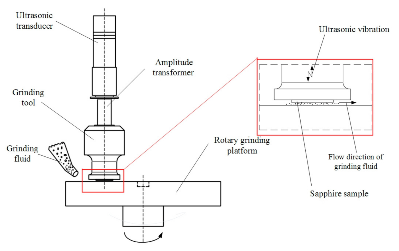
An ultrasonic grinding vibration system mainly consists of an ultrasonic transducer, amplitude transformer, and grinding tool. Figure 1 shows the schematic diagram of the non-contact ultrasonic grinding. The machining principle is that the piezoelectric ultrasonic transducer converts the high-frequency alternating current electrical signal into high-frequency ultrasonic vibration and transmits it to the amplitude transformer along the axis direction [27]. The amplitude transformer gathers energy to expand the amplitude, and then transmits the ultrasonic vibration to the working face of grinding tool [28,29]. The workpiece is stuck to the working face of the grinding tool, and the grinding surface of the workpiece maintains a specific distance from the rotary grinding platform.
According to indentation fracture mechanics, brittle fracture and plastic removal are the two main reasons for material removal, and brittle fracture is the main factor for material removal in non-contact ultrasonic grinding process. The brittle fracture mechanism of non-contact ultrasonic grinding of hard and brittle materials is as follows:
is the transverse crack; is the longitudinal crack; is the depth of the transverse crack; is the pressure load of a single abrasive particle on the workpiece; is the hardness of the workpiece material; is the breaking strength; and , , are the proportional coefficients.
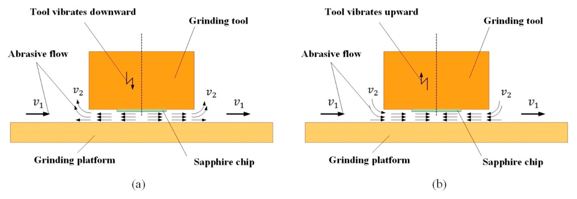
There are three main ways of material removal in non-contact ultrasonic grinding. First, the removal of workpiece surface materials by grinding particles moving with the grinding fluid, the rotation of the grinding platform and the vibration of the grinding tool working face in the grinding fluid, which are the two main factors that promote the flow of the grinding fluid. As shown in Figure 2, without considering the interference factors, the speed of grinding particles moving to the right driven by the rotation of the grinding platform is set as , and the speed of grinding particles obtained by the impact of ultrasonic vibration on the grinding fluid is set as . In one period of ultrasonic vibration, when the ultrasonic vibration shocks downward, as shown in Figure 2a, the velocity of grinding particles on the left half of the sapphire wafer is = , and the velocity of grinding particles on the right half is = . When the ultrasonic vibration shocks upward, as shown in Figure 2b, the velocity of grinding particles on the left half of the sapphire wafer is =, and the velocity of grinding particles on the right half is = . However, and are not constant, and the value of is much larger than the value of . Because of the ultrasonic vibration of the working face, the abrasive fluid is subjected to periodic pressure, which makes change periodically. The periodic changes of pressure and velocity make the abrasive fluid form turbulence. The specific formation process of turbulence is that ultrasonic vibration leads to the change in abrasive fluid flow morphology and the disappearance of the original laminar flow stability. Ultrasonic vibration causes small fluctuations in the flow layer, and the abrasive fluid forms a “vortex” under the action of transverse pressure difference and shear stress, resulting in the mixing and new disturbance of the fluid layer. The turbulent motion of the abrasive fluid is conducive to material removal. Second, is the material removal effect of ultrasonic cavitation on workpiece surface [30]. The collapse of ultrasonic cavitation bubbles can produce ultra-high pressure micro-jets locally, and the powerful impact force of micro-jets can directly or indirectly achieve the effect of removing surface materials. Third, without considering the interference of abrasive particle movement caused by abrasive fluid flow and ultrasonic cavitation, the ultrasonic vibration frequency of the working face of the grinding tool is set as , the amplitude is , and the time is , then the instantaneous vibration displacement formula of the grinding tool working face is as follows:
According to Equation (4), the instantaneous velocity of the grinding tool working face can be obtained as follows:
According to Equation (5), the instantaneous acceleration of the grinding tool working face can be obtained as:
Abrasive particles continuously impact the workpiece surface due to ultrasonic vibration of the working face. However, abrasive particles are immersed in the grinding fluid. The velocity of abrasive particles will slowly decay after the first impact with the workpiece surface. After colliding with the rotary grinding platform, the abrasive particles turn to the workpiece surface for the second impact. The velocity attenuation formula of abrasive particles in the grinding fluid is:
is the influence coefficient of fluid resistance on velocity; l is the distance between the positions where abrasive particles obtain initial velocity and where it impacts the workpiece. Under ultrasonic vibration, let the abrasive particles obtain an initial velocity , and according to Equations (5) and (7), can be described as:
According to Equation (8), the instantaneous acceleration of abrasive particles in abrasive flow can be obtained as:
3. Simulation and Test of Non-Contact Ultrasonic Grinding Vibration System
3.1. Resonant Frequency of Ultrasonic Vibration System
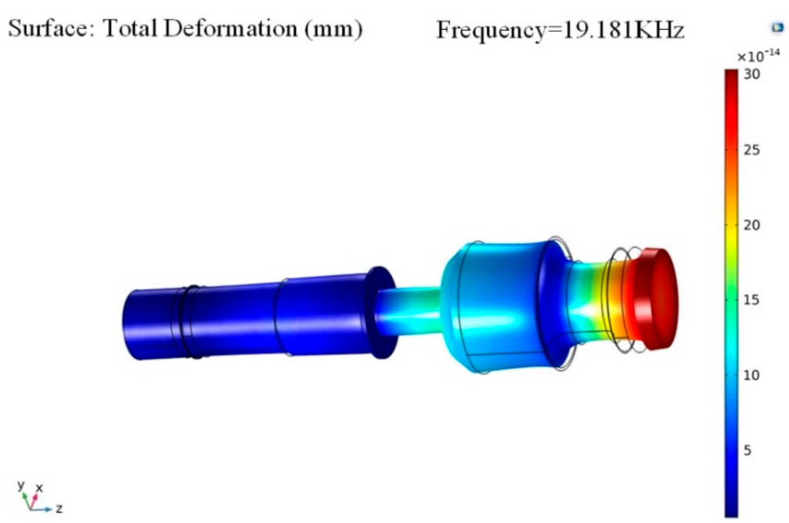
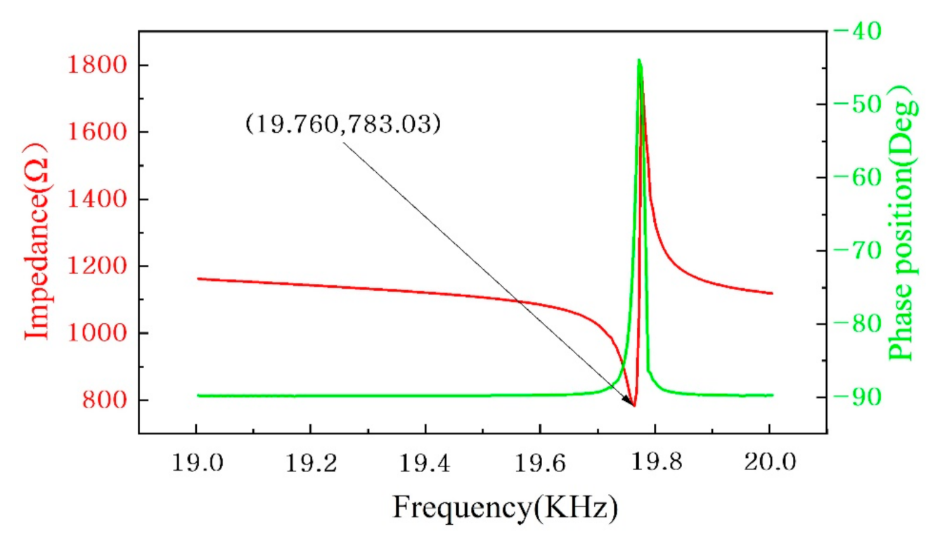
It is an important step to determine the resonant frequency of the ultrasonic vibration system before the non-contact ultrasonic grinding experiment. The resonant frequency of the vibration system was simulated and tested, respectively. The characteristic frequency of the ultrasonic vibration system was simulated by the finite element software COMSOL Multiphysics. The material settings of the ultrasonic vibration system are shown in Table 1. The piezoelectric ceramics material was PZT-8, which had a density of 7600 kg/m3, Young’s modulus of 7.65 1010 Pa, and Poisson’s ratio of 0.32. The materials of the rear cover, amplitude transformer, and grinding tool were set as structural steel, which had a density of 7850 kg/m3, Young’s modulus of 2 1011 Pa, and Poisson’s ratio of 0.30. The material of the front cover was aluminum alloy, which had a density of 2720 kg/m3, Young’s modulus of 7.2 1010 Pa, and Poisson’s ratio of 0.33. The constraint condition of simulation was set as the free state, and the reference value of the characteristic frequency search was 20 KHz. The simulation results are shown in Figure 3, where the vibration mode of the ultrasonic vibration system is different at different frequency. According to the experimental requirements, 19.181 KHz is the simulation resonant frequency of the ultrasonic vibration system. In order to verify the resonant frequency simulation results of the ultrasonic vibration system, an impedance test was carried out. Impedance of the ultrasonic vibration system was tested using a precision impedance analyzer (6630, MICROTEST, China). The test results are shown in Figure 4. Since the impedance and admittance in the circuit system are reciprocal to each other, when the impedance in the system reaches the minimum value of 783.03 , the corresponding admittance reaches the highest peak value, and the corresponding frequency is the resonance frequency of the ultrasonic vibration system. Therefore, the test resonant frequency of the ultrasonic vibration system was 19.760 KHz. Because the ultrasonic vibration system in simulation is a simplified model, there are some differences with the actual model of the ultrasonic vibration system, which is also the reason why there were some errors between the simulation result and the test result.
3.2. Working Face Amplitude of the Ultrasonic Vibration System
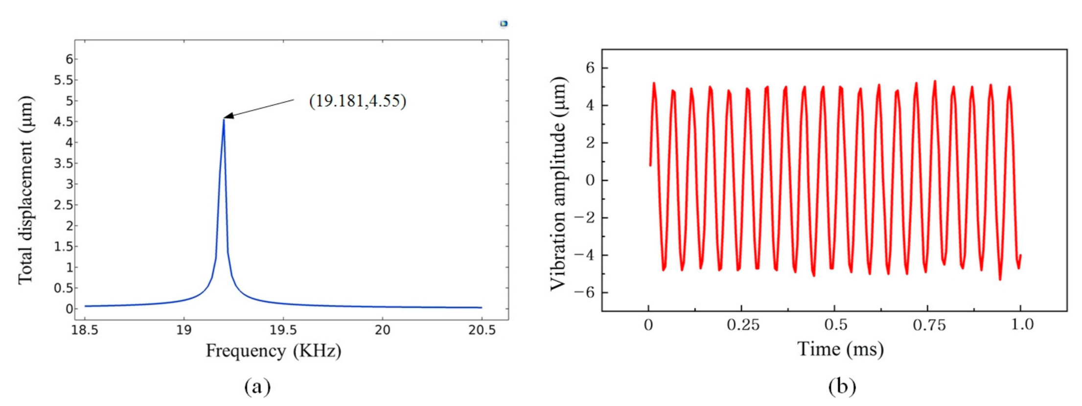
The working face amplitude of the ultrasonic vibration system is an important factor affecting the non-contact ultrasonic grinding experiment. The working face amplitude of the ultrasonic vibration system was simulated and tested, respectively. The working face amplitude of the vibration system was simulated by the finite element software COMSOL Multiphysics. The frequency domain simulation of ultrasonic vibration system was studied. The material settings of each component of the ultrasonic vibration system are shown in Table 1 above, and the clamping disk of the node position was set as the fixed constraint. Set the simulation conditions as voltage 300 V, frequency range 18.5–20.5 KHz, and step distance 0.02 KHz. The simulation results are shown in Figure 5a. When the frequency is near 19.181 KHz (simulation resonant frequency), the total displacement of the working face amplitude reaches the maximum of 4.55 μm. The working face amplitude of the ultrasonic vibration system was tested using a laser displacement sensor (LK-H020, KEYENCE, Japan). The principle of measuring amplitude by the laser displacement sensor is to capture vibration amplitude by laser focusing on the working surface of the vibration system. Set the excitation signal voltage as 300 V and the frequency as 19.760 KHz (test resonant frequency). The sampling period of the laser displacement sensor was 5 μs, and 200 continuous sampling points were taken out. The test results are shown in Figure 5b, where the average value of the vibration amplitude reached 5 μm.
4. Experiment Study of Non-Contact Ultrasonic Grinding
4.1. Experimental Setup
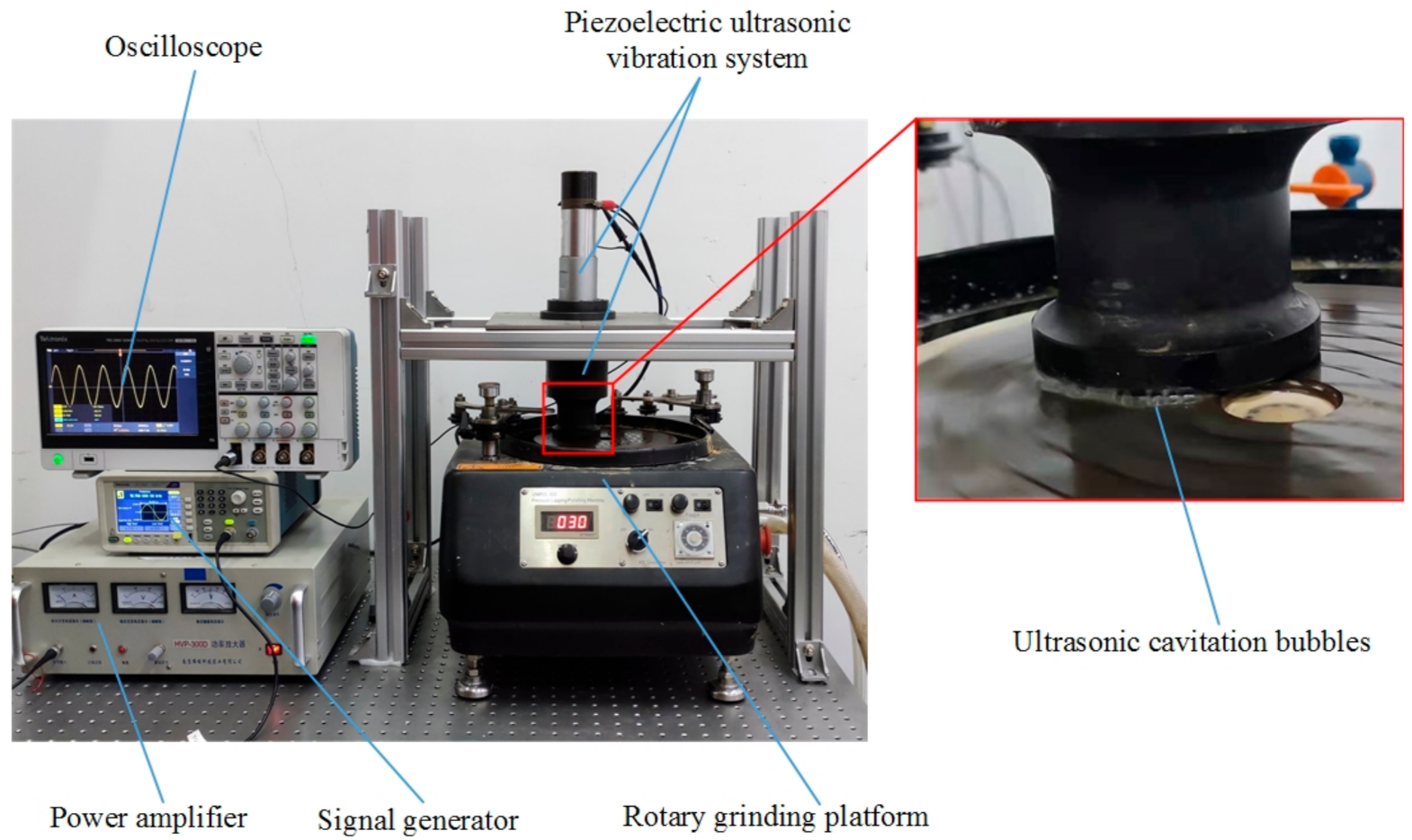
The non-contact ultrasonic grinding experimental device is shown in Figure 6. The experimental device consisted of a signal generator, power amplifier, oscilloscope, piezoelectric ultrasonic vibration system, and rotary grinding platform. The experimental conditions are listed in Table 2. The working principle of the experimental device is to obtain an appropriate excitation signal by adjusting the signal generator and the power amplifier. The excitation signal was set as an alternating current signal with the voltage of 300 V (peak-to-peak value) and the frequency of 19.760 KHz (test resonance frequency). The ultrasonic vibration system converts the excitation signal into ultrasonic vibration and outputs it from the working face. The sapphire wafer was fixed on the working face. The experiment was carried out with alumina particle grinding liquid. The rotation speed of the grinding platform was 30 r/min, and the non-contact distance between the grinding surface of the sapphire sample with the rotary grinding platform was 1 mm. The contrast experimental group of contact traditional grinding under certain pre-pressure was set. Two groups of comparative experimental samples with similar mass and surface roughness values were selected for the experiment. As shown in Figure 6, in the non-contact ultrasonic grinding experiment, ultrasonic vibration caused a large number of ultrasonic cavitation bubbles to be generated in the gap between the working end face and the rotary grinding platform.
4.2. Results and Discussions
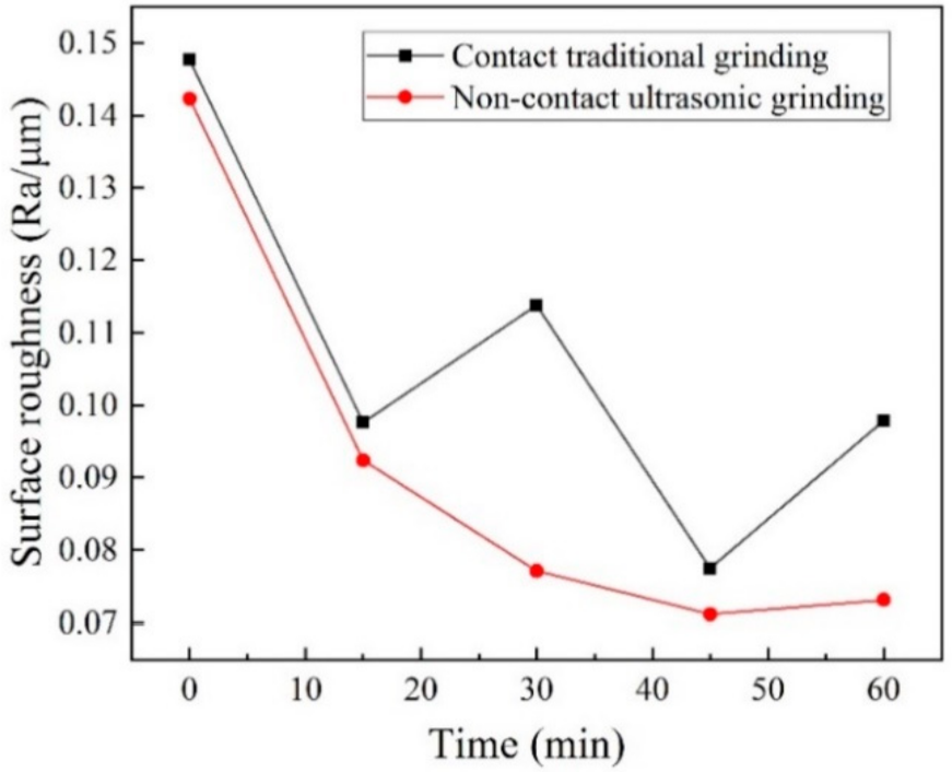
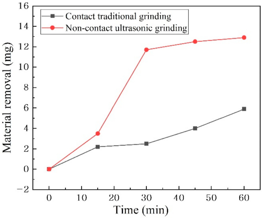
A surface topography measuring instrument (XM-200, LUOYANG BEARING RESEARCH INSTITUTE, Luoyang, China) was used to detect and record the roughness data every 15 min as a phase, and the results are shown in Figure 7. During the 0–15 min phase of the experiment, the surface roughness values of the samples in the two groups of non-contact ultrasonic grinding and contact traditional grinding decreased significantly. During the 15–30 min and 30–45 min phases, the roughness values of the samples in the non-contact ultrasonic grinding group still decreased significantly, while the roughness values of the samples in the contact traditional grinding group decreased slowly. During the 45–60 min phase, the surface roughness of the samples in both groups increased slightly due to the long grinding time, while the surface roughness of the samples in the contact traditional grinding group increased more obviously. The high-precision electronic scale (JJ24BC, G&G MEASUREMENT PLANT, Changshu, China) was used to detect and record the material removal amount. Every 15 min was a stage, and the results are shown in Figure 8. In all four experimental stages, the sapphire sample material removal rate of non-contact ultrasonic grinding was higher than that of contact traditional grinding. The material removal rate of non-contact ultrasonic grinding increased greatly in 0–15 min and 15–30 min stages, while that of contact traditional grinding maintained a small increase. In conclusion, non-contact ultrasonic grinding has obvious advantages in reducing material surface roughness and improving processing efficiency compared with contact traditional grinding.
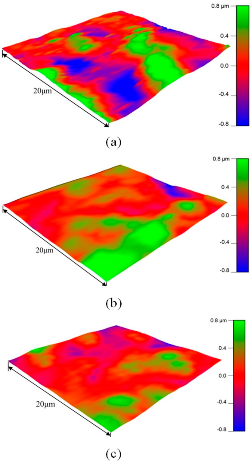
Two groups of sapphire samples with similar initial surface morphology were used for 60 min non-contact ultrasonic grinding and traditional contact grinding experiments, respectively. Atomic force microscopy (MFP-3D, Asylum Research, Santa Barbara, CA, USA) was used to observe the changes in sample surface morphology before and after the two groups of experiments. The results are shown in Figure 9. The surface morphology of the sapphire samples in the non-contact ultrasonic grinding group was flatter and smoother than that in the traditional contact grinding group.
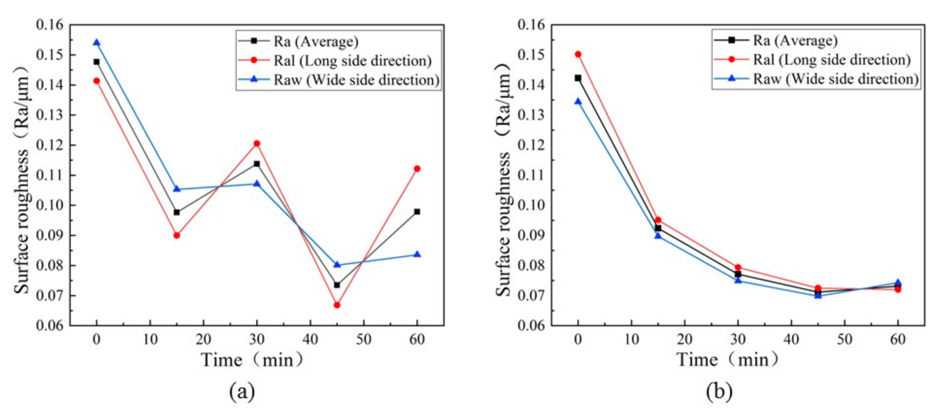
In the traditional contact grinding process, due to the difference in the local force on the workpiece and the influence of the free abrasive movement, it is easy to cause the local aggregation of free abrasive on the workpiece grinding surface, which leads to the phenomenon of uneven grinding. The grinding uniformity of non-contact ultrasonic grinding was studied, and the comparison experiment of traditional contact grinding was set up. When the rotation speed of the grinding platform was 30 r/min, the roughness values of the two groups of experiments were detected and recorded every 15 min. The surface roughness value in the long side direction (Ral), the surface roughness value in the wide side direction (Raw), and average surface roughness value (Ra) of the sapphire samples were measured respectively. As shown in Figure 10a, the surface roughness value of the traditional contact grind sapphire sample fluctuated unsteadily. The roughness value measured in different directions of the grinding surface was different, and this difference gradually expanded with the increase in grinding time. As shown in Figure 10b, non-contact ultrasonic grinding could steadily reduce the surface roughness of the sapphire samples. The roughness values measured in different directions had a consistent trend, and the differences were gradually eliminated with the increase in grinding time.
5. Conclusions
This paper proposes a non-contact ultrasonic grinding processing method, which can effectively avoid the phenomenon of grinding tool wear on the workpiece due to the difficult control of pre-pressure in contact ultrasonic grinding. The main material removal mechanisms of non-contact ultrasonic grinding were analyzed. The resonant frequency of the ultrasonic vibration system and vibration amplitude of the grinding tool working face were simulated and experimentally tested. In the simulation, when the frequency was near 19.181 KHz (simulation resonant frequency), the vibration amplitude of the grinding tool working face was 4.55 μm. In the test experiment, when the frequency was 19.760 KHz (test resonant frequency), the vibration amplitude of the grinding tool working face reached an average value of 5 μm. Set the frequency of the alternating current electrical signal as 19.760 KHz, the voltage as 300 V (peak to peak), and the rotation speed of the grinding platform as 30 r/min. The non-contact ultrasonic grinding experiment of the sapphire wafer was carried out for 60 min. The results show that non-contact ultrasonic grinding of sapphire wafer can reduce the surface roughness by 48.6% and the material removal amount was 12.9 mg. Compared with traditional contact grinding, the results show that non-contact ultrasonic grinding was better in reducing the surface roughness and improving the processing efficiency of the sapphire wafers. Meanwhile, non-contact ultrasonic grinding could effectively avoid the uneven grinding quality caused by uneven force and grinding fluid aggregation in traditional contact grinding. Non-contact ultrasonic grinding can provide new ideas for ultrasonic grinding of hard and brittle materials.
Author Contributions
Conceptualization, W.H. and D.A.; Writing-original draft, Q.Z.; Writing-review and editing, D.A. and W.H.; Experiment and simulation, C.Y., Q.Z. and Y.Z.; Funding acquisition, W.H. and D.A. All authors have read and agreed to the published version of the manuscript.
Funding
This research was funded by the Science and Technology Planning Project of Guangzhou, China (No. 202002030418) and the National Natural Science Foundation of China (No. 52075108).
Institutional Review Board Statement
Not applicable.
Informed Consent Statement
Not applicable.
Data Availability Statement
Not applicable.
Conflicts of Interest
The authors declare no potential conflicts of interest with respect to the research, authorship, and/or publication of this article.
References
- Akselrod, M.S.; Bruni, F.J. Modern trends in crystal growth and new applications of sapphire. J. Cryst. Growth 2012, 360, 134–145. [Google Scholar] [CrossRef]
- Gagliardi, J.J.; Kim, D.; Sokol, J.J.; Zazzera, L.A.; Romero, V.D.; Atkinson, M.R.; Nabulsi, F.; Zhang, H. A case for 2-body material removal in prime LED sapphire substrate lapping and polishing. J. Manuf. Process. 2013, 15, 348–354. [Google Scholar] [CrossRef]
- Ma, J.; Thomas, M.E.; McGuiggan, P.; Spicer, J.B. Weak absorption and scattering losses from the visible to the near-infrared in single-crystal sapphire materials. Opt. Eng. 2020, 59, 087101. [Google Scholar] [CrossRef]
- Chen, J.; Zhu, N.; Niu, F.; Peng, Y.; Su, J.; Zhu, Y. Influence of agglomerated diamond abrasive wear on sapphire material removal behavior. Diam. Relat. Mater. 2020, 108, 107965. [Google Scholar] [CrossRef]
- Li, Z.C.; Pei, Z.J.; Funkenbusch, P.D. Machining processes for sapphire wafers: A literature review. Proc. Inst. Mech. Eng. Part B J. Eng. Manuf. 2011, 225, 975–989. [Google Scholar] [CrossRef]
- Lye, C.S.M.; Wang, Z.K.; Lam, Y.C. Mechanism and effects of surface morphology on absorption characteristics in ultrashort pulse laser processing of sapphire. Appl. Surf. Sci. 2021, 542, 148734. [Google Scholar] [CrossRef]
- Luo, B.; Yan, Q.; Pan, J.; Lu, J.; Huang, Z. Influences of processing parameters on metal-bonded diamond wheel wear when grinding a sapphire wafer. Diam. Relat. Mater. 2021, 113, 108275. [Google Scholar] [CrossRef]
- Xu, Y.; Lu, J.; Xu, X. Study on planarization machining of sapphire wafer with soft-hard mixed abrasive through mechanical chemical polishing. Appl. Surf. Sci. 2016, 389, 713–720. [Google Scholar] [CrossRef]
- Abbasi, A.; Amini, S.; Sheikhzadeh, G.A. Effect of ultrasonic peening technology on the thermal fatigue of rolling mill rolls. Int. J. Adv. Manuf. Technol. 2018, 94, 2499–2513. [Google Scholar] [CrossRef]
- Bai, Y.; Tuncdemir, S.; Guo, J.; Uchino, K. Analysis of longitudinal and torsional resonance vibrations of a piezoelectrically excited bar by introducing piezoelectric loss coefficients. J. Intell. Mater. Syst. Struct. 2012, 23, 453–462. [Google Scholar] [CrossRef]
- Li, D.; Tang, J.; Chen, H.; Shao, W. Study on grinding force model in ultrasonic vibration-assisted grinding of alloy structural steel. Int. J. Adv. Manuf. Technol. 2019, 101, 1467–1479. [Google Scholar] [CrossRef]
- Zhao, Q.; Sun, Z.; Guo, B. Material removal mechanism in ultrasonic vibration assisted polishing of micro cylindrical surface on SiC. Int. J. Mach. Tools Manuf. 2016, 103, 28–39. [Google Scholar] [CrossRef]
- Zhu, X.-X.; Wang, W.-H.; Jiang, R.-S.; Zhang, Z.-F.; Huang, B.; Ma, X.-W. Research on ultrasonic-assisted drilling in micro-hole machining of the DD6 superalloy. Adv. Manuf. 2020, 8, 405–417. [Google Scholar] [CrossRef]
- Liang, Z.; Ma, Y.; Nie, Q.; Wang, X.; Zhou, T.; Guo, H.; Sun, X.; Jiang, L. Ultrasonic cavitation and vibration hybrid-assisted micro-drilling of stainless steel. Int. J. Adv. Manuf. Technol. 2019, 104, 3073–3082. [Google Scholar] [CrossRef]
- Zhou, W.; Tang, J.; Chen, H.; Shao, W. A comprehensive investigation of surface generation and material removal characteristics in ultrasonic vibration assisted grinding. Int. J. Mech. Sci. 2019, 156, 14–30. [Google Scholar] [CrossRef]
- Xu, W.; Lu, X.; Pan, G.; Lei, Y.; Luo, J. Ultrasonic flexural vibration assisted chemical mechanical polishing for sapphire substrate. Appl. Surf. Sci. 2010, 256, 3936–3940. [Google Scholar] [CrossRef]
- Zhao, B.; Chang, B.Q.; Wang, X.B.; Bie, W.B. System design and experimental research on ultrasonic assisted elliptical vibration grinding of Nano-ZrO2 ceramics. Ceram. Int. 2019, 45, 24865–24877. [Google Scholar] [CrossRef]
- Hu, Y.; Shi, D.; Hu, Y.; Zhao, H.; Sun, X. Investigation on the Material Removal and Surface Generation of a Single Crystal SiC Wafer by Ultrasonic Chemical Mechanical Polishing Combined with Ultrasonic Lapping. Materials 2018, 11, 2022. [Google Scholar] [CrossRef] [PubMed] [Green Version]
- Ralchenko, V.G.; Ashkinazi, E.E.; Zavedeev, E.V.; Khomich, A.A.; Bolshakov, A.P.; Ryzhkov, S.G.; Sovyk, D.N.; Shershulin, V.A.; Yurov, V.Y.; Rudnev, V.V. High-rate ultrasonic polishing of polycrystalline diamond films. Diam. Relat. Mater. 2016, 66, 171–176. [Google Scholar] [CrossRef]
- Baraheni, M.; Amini, S. Mathematical model to predict cutting force in rotary ultrasonic assisted end grinding of Si3N4 considering both ductile and brittle deformation. Measurement 2020, 156, 107586. [Google Scholar] [CrossRef]
- Ning, F.; Cong, W.; Wang, H.; Hu, Y.; Hu, Z.; Pei, Z. Surface grinding of CFRP composites with rotary ultrasonic machining: A mechanistic model on cutting force in the feed direction. Int. J. Adv. Manuf. Technol. 2017, 92, 1217–1229. [Google Scholar] [CrossRef]
- Wang, H.; Pei, Z.J.; Cong, W.L. A mechanistic cutting force model based on ductile and brittle fracture material removal modes for edge surface grinding of CFRP composites using rotary ultrasonic machining. Int. J. Mech. Sci. 2020, 176, 105551. [Google Scholar] [CrossRef]
- Liu, Q.; Wang, H.; Feng, J.; Zhou, X.; Wang, R.; Xu, P. Study of ultrasonic-hydration compound polishing for sapphire optical channel. AIP Adv. 2019, 9, 105310. [Google Scholar] [CrossRef]
- Qiao, J.P.; Feng, M.; Li, Y.; Li, S.S.; Zeng, J.; Wu, Y.B. A study on tangential ultrasonic-assisted mirror grinding of zirconia ceramic curved surfaces. Int. J. Adv. Manuf. Technol. 2021, 112, 2837–2851. [Google Scholar] [CrossRef]
- Yu, T.; Zhang, T.; Yang, T.; Zhao, J. CFD simulation and experimental studies of suspension flow field in ultrasonic polishing. J. Mater. Process. Technol. 2019, 266, 715–725. [Google Scholar] [CrossRef]
- Ichida, Y.; Sato, R.; Morimoto, Y.; Kobayashi, K. Material removal mechanisms in non-contact ultrasonic abrasive machining. Wear 2005, 258, 107–114. [Google Scholar] [CrossRef]
- Dunst, P.; Hemsel, T.; Bornmann, P.; Littmann, W.; Sextro, W. Optimization of Ultrasonic Acoustic Standing Wave Systems. Actuators 2020, 9, 9. [Google Scholar] [CrossRef] [Green Version]
- Omori, K.; Fujimoto, N.; Kanda, T.; Wakimoto, S.; Seno, N. Core-Shell Droplet Generation Device Using a Flexural Bolt-Clamped Langevin-Type Ultrasonic Transducer. Actuators 2021, 10, 55. [Google Scholar] [CrossRef]
- Wei, Z.; Kosterman, J.A.; Xiao, R.; Pee, G.-Y.; Cai, M.; Weavers, L.K. Designing and characterizing a multi-stepped ultrasonic horn for enhanced sonochemical performance. Ultrason. Sonochem. 2015, 27, 325–333. [Google Scholar] [CrossRef] [PubMed] [Green Version]
- Tan, K.L.; Yeo, S.H. Surface finishing on IN625 additively manufactured surfaces by combined ultrasonic cavitation and abrasion. Addit. Manuf. 2020, 31, 100938. [Google Scholar] [CrossRef]
Figure 1.
Schematic diagram of non-contact ultrasonic grinding processing.

Figure 2.
Material removal principle of abrasive fluid shear flow in (a) the first half vibration period, and (b) the second half vibration period.
Figure 2.
Material removal principle of abrasive fluid shear flow in (a) the first half vibration period, and (b) the second half vibration period.

Figure 3.
Modal analysis of the ultrasonic vibration system.

Figure 4.
Impedance test of the ultrasonic vibration system.

Figure 5.
Ultrasonic vibration amplitude of grinding tool working face: (a) simulation results, and (b) test results.
Figure 5.
Ultrasonic vibration amplitude of grinding tool working face: (a) simulation results, and (b) test results.

Figure 6.
Experiment diagram of non-contact ultrasonic grinding sapphire.

Figure 7.
Comparison of surface roughness result between non-contact ultrasonic grinding and traditional contact grinding.
Figure 7.
Comparison of surface roughness result between non-contact ultrasonic grinding and traditional contact grinding.

Figure 8.
Comparison of material removal result between non-contact ultrasonic grinding and traditional contact grinding.
Figure 8.
Comparison of material removal result between non-contact ultrasonic grinding and traditional contact grinding.

Figure 9.
Surface morphology of the sapphire sample. (a) Initial surface topography, (b) after traditional contact grinding for 60 min, and (c) after non-contact ultrasonic grinding for 60 min.
Figure 9.
Surface morphology of the sapphire sample. (a) Initial surface topography, (b) after traditional contact grinding for 60 min, and (c) after non-contact ultrasonic grinding for 60 min.

Figure 10.
Comparison of surface roughness in different test directions between (a) traditional contact grinding and (b) non-contact ultrasonic grinding.
Figure 10.
Comparison of surface roughness in different test directions between (a) traditional contact grinding and (b) non-contact ultrasonic grinding.


Table 1.
Material setup for the ultrasonic vibration system in simulation.
| Components | Materials |
|---|---|
| Ultrasonic Transducer | |
| Rear cover | Structural steel |
| Piezoelectric ceramic ring | PZT-8 |
| Front cover (Connect the amplitude transformer) | Aluminum alloy |
| Amplitude transformer | Structural steel |
| Grinding tool | Structural steel |
Table 2.
Experimental conditions.
| Items | Parameter Values |
|---|---|
| Workpiece | Sapphire wafer (main ingredient is alumina) |
| Grinding fluid | Alumina particle grinding fluid |
| Rotating speed of rotary grinding platform | 30 r/min |
| Ultrasonic vibration system parameters | |
| Resonant frequency | 19.760 KHz |
| Voltage | 300 V |
| Ultrasonic vibration amplitude of working face | 5 μm |
Publisher’s Note: MDPI stays neutral with regard to jurisdictional claims in published maps and institutional affiliations. |
© 2021 by the authors. Licensee MDPI, Basel, Switzerland. This article is an open access article distributed under the terms and conditions of the Creative Commons Attribution (CC BY) license (https://creativecommons.org/licenses/by/4.0/).
Share and Cite
MDPI and ACS Style
Huang, W.; Zhong, Q.; An, D.; Yang, C.; Zhang, Y. Mechanism and Experiment Study of Non-Contact Ultrasonic Assisted Grinding. Actuators 2021, 10, 238. https://0-doi-org.brum.beds.ac.uk/10.3390/act10090238
AMA Style
Huang W, Zhong Q, An D, Yang C, Zhang Y. Mechanism and Experiment Study of Non-Contact Ultrasonic Assisted Grinding. Actuators. 2021; 10(9):238. https://0-doi-org.brum.beds.ac.uk/10.3390/act10090238
Chicago/Turabian StyleHuang, Weiqing, Qunyou Zhong, Dawei An, Chenglong Yang, and Yi Zhang. 2021. "Mechanism and Experiment Study of Non-Contact Ultrasonic Assisted Grinding" Actuators 10, no. 9: 238. https://0-doi-org.brum.beds.ac.uk/10.3390/act10090238
Note that from the first issue of 2016, this journal uses article numbers instead of page numbers. See further details here.